EP3978791A1 - Structural midframe for an electronic device, and associated devices and methods - Google Patents
Structural midframe for an electronic device, and associated devices and methods Download PDFInfo
- Publication number
- EP3978791A1 EP3978791A1 EP21192698.5A EP21192698A EP3978791A1 EP 3978791 A1 EP3978791 A1 EP 3978791A1 EP 21192698 A EP21192698 A EP 21192698A EP 3978791 A1 EP3978791 A1 EP 3978791A1
- Authority
- EP
- European Patent Office
- Prior art keywords
- midframe
- electronic device
- housing member
- board
- onto
- Prior art date
- Legal status (The legal status is an assumption and is not a legal conclusion. Google has not performed a legal analysis and makes no representation as to the accuracy of the status listed.)
- Pending
Links
- 238000000034 method Methods 0.000 title claims abstract description 33
- 239000000463 material Substances 0.000 claims description 14
- 230000013011 mating Effects 0.000 claims description 4
- 229910000679 solder Inorganic materials 0.000 claims description 3
- 238000013461 design Methods 0.000 abstract description 2
- 239000004820 Pressure-sensitive adhesive Substances 0.000 description 7
- 239000002537 cosmetic Substances 0.000 description 4
- 239000004417 polycarbonate Substances 0.000 description 4
- 229920000515 polycarbonate Polymers 0.000 description 4
- 239000000853 adhesive Substances 0.000 description 3
- 230000001070 adhesive effect Effects 0.000 description 3
- 238000001514 detection method Methods 0.000 description 3
- 238000004519 manufacturing process Methods 0.000 description 3
- 230000008439 repair process Effects 0.000 description 3
- 238000012360 testing method Methods 0.000 description 3
- 238000012546 transfer Methods 0.000 description 3
- 230000001815 facial effect Effects 0.000 description 2
- 238000001746 injection moulding Methods 0.000 description 2
- 239000010410 layer Substances 0.000 description 2
- 229910052751 metal Inorganic materials 0.000 description 2
- 239000002184 metal Substances 0.000 description 2
- 150000002739 metals Chemical class 0.000 description 2
- 238000000465 moulding Methods 0.000 description 2
- 239000003973 paint Substances 0.000 description 2
- 239000002356 single layer Substances 0.000 description 2
- 239000000243 solution Substances 0.000 description 2
- 239000004593 Epoxy Substances 0.000 description 1
- 239000004677 Nylon Substances 0.000 description 1
- 238000007796 conventional method Methods 0.000 description 1
- 230000001419 dependent effect Effects 0.000 description 1
- 239000003989 dielectric material Substances 0.000 description 1
- 230000000694 effects Effects 0.000 description 1
- 238000005516 engineering process Methods 0.000 description 1
- 239000002783 friction material Substances 0.000 description 1
- 230000006870 function Effects 0.000 description 1
- 239000000314 lubricant Substances 0.000 description 1
- 238000012986 modification Methods 0.000 description 1
- 230000004048 modification Effects 0.000 description 1
- 229920001778 nylon Polymers 0.000 description 1
- 239000004033 plastic Substances 0.000 description 1
- 239000007787 solid Substances 0.000 description 1
- 229920001169 thermoplastic Polymers 0.000 description 1
Images


Classifications
-
- H—ELECTRICITY
- H05—ELECTRIC TECHNIQUES NOT OTHERWISE PROVIDED FOR
- H05K—PRINTED CIRCUITS; CASINGS OR CONSTRUCTIONAL DETAILS OF ELECTRIC APPARATUS; MANUFACTURE OF ASSEMBLAGES OF ELECTRICAL COMPONENTS
- H05K7/00—Constructional details common to different types of electric apparatus
- H05K7/14—Mounting supporting structure in casing or on frame or rack
- H05K7/1417—Mounting supporting structure in casing or on frame or rack having securing means for mounting boards, plates or wiring boards
-
- F—MECHANICAL ENGINEERING; LIGHTING; HEATING; WEAPONS; BLASTING
- F16—ENGINEERING ELEMENTS AND UNITS; GENERAL MEASURES FOR PRODUCING AND MAINTAINING EFFECTIVE FUNCTIONING OF MACHINES OR INSTALLATIONS; THERMAL INSULATION IN GENERAL
- F16M—FRAMES, CASINGS OR BEDS OF ENGINES, MACHINES OR APPARATUS, NOT SPECIFIC TO ENGINES, MACHINES OR APPARATUS PROVIDED FOR ELSEWHERE; STANDS; SUPPORTS
- F16M11/00—Stands or trestles as supports for apparatus or articles placed thereon ; Stands for scientific apparatus such as gravitational force meters
- F16M11/02—Heads
- F16M11/04—Means for attachment of apparatus; Means allowing adjustment of the apparatus relatively to the stand
- F16M11/041—Allowing quick release of the apparatus
-
- F—MECHANICAL ENGINEERING; LIGHTING; HEATING; WEAPONS; BLASTING
- F16—ENGINEERING ELEMENTS AND UNITS; GENERAL MEASURES FOR PRODUCING AND MAINTAINING EFFECTIVE FUNCTIONING OF MACHINES OR INSTALLATIONS; THERMAL INSULATION IN GENERAL
- F16M—FRAMES, CASINGS OR BEDS OF ENGINES, MACHINES OR APPARATUS, NOT SPECIFIC TO ENGINES, MACHINES OR APPARATUS PROVIDED FOR ELSEWHERE; STANDS; SUPPORTS
- F16M11/00—Stands or trestles as supports for apparatus or articles placed thereon ; Stands for scientific apparatus such as gravitational force meters
- F16M11/02—Heads
- F16M11/04—Means for attachment of apparatus; Means allowing adjustment of the apparatus relatively to the stand
- F16M11/06—Means for attachment of apparatus; Means allowing adjustment of the apparatus relatively to the stand allowing pivoting
- F16M11/12—Means for attachment of apparatus; Means allowing adjustment of the apparatus relatively to the stand allowing pivoting in more than one direction
- F16M11/14—Means for attachment of apparatus; Means allowing adjustment of the apparatus relatively to the stand allowing pivoting in more than one direction with ball-joint
-
- F—MECHANICAL ENGINEERING; LIGHTING; HEATING; WEAPONS; BLASTING
- F16—ENGINEERING ELEMENTS AND UNITS; GENERAL MEASURES FOR PRODUCING AND MAINTAINING EFFECTIVE FUNCTIONING OF MACHINES OR INSTALLATIONS; THERMAL INSULATION IN GENERAL
- F16M—FRAMES, CASINGS OR BEDS OF ENGINES, MACHINES OR APPARATUS, NOT SPECIFIC TO ENGINES, MACHINES OR APPARATUS PROVIDED FOR ELSEWHERE; STANDS; SUPPORTS
- F16M13/00—Other supports for positioning apparatus or articles; Means for steadying hand-held apparatus or articles
- F16M13/02—Other supports for positioning apparatus or articles; Means for steadying hand-held apparatus or articles for supporting on, or attaching to, an object, e.g. tree, gate, window-frame, cycle
- F16M13/022—Other supports for positioning apparatus or articles; Means for steadying hand-held apparatus or articles for supporting on, or attaching to, an object, e.g. tree, gate, window-frame, cycle repositionable
-
- F—MECHANICAL ENGINEERING; LIGHTING; HEATING; WEAPONS; BLASTING
- F16—ENGINEERING ELEMENTS AND UNITS; GENERAL MEASURES FOR PRODUCING AND MAINTAINING EFFECTIVE FUNCTIONING OF MACHINES OR INSTALLATIONS; THERMAL INSULATION IN GENERAL
- F16M—FRAMES, CASINGS OR BEDS OF ENGINES, MACHINES OR APPARATUS, NOT SPECIFIC TO ENGINES, MACHINES OR APPARATUS PROVIDED FOR ELSEWHERE; STANDS; SUPPORTS
- F16M13/00—Other supports for positioning apparatus or articles; Means for steadying hand-held apparatus or articles
- F16M13/02—Other supports for positioning apparatus or articles; Means for steadying hand-held apparatus or articles for supporting on, or attaching to, an object, e.g. tree, gate, window-frame, cycle
- F16M13/027—Ceiling supports
-
- G—PHYSICS
- G03—PHOTOGRAPHY; CINEMATOGRAPHY; ANALOGOUS TECHNIQUES USING WAVES OTHER THAN OPTICAL WAVES; ELECTROGRAPHY; HOLOGRAPHY
- G03B—APPARATUS OR ARRANGEMENTS FOR TAKING PHOTOGRAPHS OR FOR PROJECTING OR VIEWING THEM; APPARATUS OR ARRANGEMENTS EMPLOYING ANALOGOUS TECHNIQUES USING WAVES OTHER THAN OPTICAL WAVES; ACCESSORIES THEREFOR
- G03B17/00—Details of cameras or camera bodies; Accessories therefor
- G03B17/56—Accessories
- G03B17/561—Support related camera accessories
-
- G—PHYSICS
- G08—SIGNALLING
- G08B—SIGNALLING OR CALLING SYSTEMS; ORDER TELEGRAPHS; ALARM SYSTEMS
- G08B13/00—Burglar, theft or intruder alarms
- G08B13/18—Actuation by interference with heat, light, or radiation of shorter wavelength; Actuation by intruding sources of heat, light, or radiation of shorter wavelength
- G08B13/189—Actuation by interference with heat, light, or radiation of shorter wavelength; Actuation by intruding sources of heat, light, or radiation of shorter wavelength using passive radiation detection systems
- G08B13/194—Actuation by interference with heat, light, or radiation of shorter wavelength; Actuation by intruding sources of heat, light, or radiation of shorter wavelength using passive radiation detection systems using image scanning and comparing systems
- G08B13/196—Actuation by interference with heat, light, or radiation of shorter wavelength; Actuation by intruding sources of heat, light, or radiation of shorter wavelength using passive radiation detection systems using image scanning and comparing systems using television cameras
- G08B13/19617—Surveillance camera constructional details
-
- H—ELECTRICITY
- H01—ELECTRIC ELEMENTS
- H01Q—ANTENNAS, i.e. RADIO AERIALS
- H01Q1/00—Details of, or arrangements associated with, antennas
- H01Q1/12—Supports; Mounting means
- H01Q1/22—Supports; Mounting means by structural association with other equipment or articles
- H01Q1/24—Supports; Mounting means by structural association with other equipment or articles with receiving set
-
- H—ELECTRICITY
- H01—ELECTRIC ELEMENTS
- H01Q—ANTENNAS, i.e. RADIO AERIALS
- H01Q9/00—Electrically-short antennas having dimensions not more than twice the operating wavelength and consisting of conductive active radiating elements
- H01Q9/04—Resonant antennas
- H01Q9/0407—Substantially flat resonant element parallel to ground plane, e.g. patch antenna
-
- H—ELECTRICITY
- H04—ELECTRIC COMMUNICATION TECHNIQUE
- H04N—PICTORIAL COMMUNICATION, e.g. TELEVISION
- H04N23/00—Cameras or camera modules comprising electronic image sensors; Control thereof
- H04N23/50—Constructional details
- H04N23/51—Housings
-
- H—ELECTRICITY
- H04—ELECTRIC COMMUNICATION TECHNIQUE
- H04N—PICTORIAL COMMUNICATION, e.g. TELEVISION
- H04N23/00—Cameras or camera modules comprising electronic image sensors; Control thereof
- H04N23/50—Constructional details
- H04N23/52—Elements optimising image sensor operation, e.g. for electromagnetic interference [EMI] protection or temperature control by heat transfer or cooling elements
-
- H—ELECTRICITY
- H04—ELECTRIC COMMUNICATION TECHNIQUE
- H04N—PICTORIAL COMMUNICATION, e.g. TELEVISION
- H04N23/00—Cameras or camera modules comprising electronic image sensors; Control thereof
- H04N23/50—Constructional details
- H04N23/54—Mounting of pick-up tubes, electronic image sensors, deviation or focusing coils
-
- H—ELECTRICITY
- H04—ELECTRIC COMMUNICATION TECHNIQUE
- H04N—PICTORIAL COMMUNICATION, e.g. TELEVISION
- H04N23/00—Cameras or camera modules comprising electronic image sensors; Control thereof
- H04N23/57—Mechanical or electrical details of cameras or camera modules specially adapted for being embedded in other devices
-
- H—ELECTRICITY
- H05—ELECTRIC TECHNIQUES NOT OTHERWISE PROVIDED FOR
- H05K—PRINTED CIRCUITS; CASINGS OR CONSTRUCTIONAL DETAILS OF ELECTRIC APPARATUS; MANUFACTURE OF ASSEMBLAGES OF ELECTRICAL COMPONENTS
- H05K7/00—Constructional details common to different types of electric apparatus
- H05K7/20—Modifications to facilitate cooling, ventilating, or heating
- H05K7/2039—Modifications to facilitate cooling, ventilating, or heating characterised by the heat transfer by conduction from the heat generating element to a dissipating body
-
- G—PHYSICS
- G08—SIGNALLING
- G08B—SIGNALLING OR CALLING SYSTEMS; ORDER TELEGRAPHS; ALARM SYSTEMS
- G08B13/00—Burglar, theft or intruder alarms
- G08B13/18—Actuation by interference with heat, light, or radiation of shorter wavelength; Actuation by intruding sources of heat, light, or radiation of shorter wavelength
- G08B13/189—Actuation by interference with heat, light, or radiation of shorter wavelength; Actuation by intruding sources of heat, light, or radiation of shorter wavelength using passive radiation detection systems
- G08B13/194—Actuation by interference with heat, light, or radiation of shorter wavelength; Actuation by intruding sources of heat, light, or radiation of shorter wavelength using passive radiation detection systems using image scanning and comparing systems
- G08B13/196—Actuation by interference with heat, light, or radiation of shorter wavelength; Actuation by intruding sources of heat, light, or radiation of shorter wavelength using passive radiation detection systems using image scanning and comparing systems using television cameras
- G08B13/19654—Details concerning communication with a camera
Definitions
- reducing the production cost may include reducing the complexity of a device's components and/or the number of steps used in the assembly process.
- Some devices with a small form factor have limited available space within a housing for operators and tools to assemble internal components. Consequently, there may be insufficient clearance for the operator or tool to easily access areas within the housing to fasten components together.
- One solution is to fix multiple internal components to the housing; however, using the housing as a structural member may result in a more-complex housing geometry and, in some cases, a device that is difficult to rework.
- the present document describes an electronic device with a (structural) midframe and associated methods.
- the proposed solution is defined by the accompanying independent claims. Potential embodiments are in particular defined by the dependent claims.
- the architectural design of the electronic device may be such that its components are assembled onto the midframe to form a midframe subassembly and the midframe subassembly may then be placed in a portion of the housing.
- the midframe may include various features that enable multiple printed circuit boards, a camera subassembly, a front housing member, a heatsink, and a heat spreader to be assembled onto the midframe outside of the housing.
- the midframe can also include a hinge-bearing surface forming a portion of a ball joint for supporting rotational movement of the electronic device. Accordingly, the electronic device can use the midframe, rather than the housing, as a structural member.
- a midframe as described herein can allow the majority of internal components of the electronic device to be assembled onto the midframe to form a midframe subassembly outside of the housing, wherein the housing can be assembled onto the electronic device last.
- This enables the housing to maintain a simple geometry (with less mounting features), which in turn enables the housing to be a cheaper, more environmentally-friendly, as-molded cosmetic part (without requiring paint to achieve a desired gloss level or cover molding imperfections).
- fewer components may be fixed to the housing, which increases the reworkability of the electronic device. Because the housing ( e .
- g ., cosmetic enclosure may be assembled after a midframe subassembly, additional testing may be performed on the midframe subassembly ( e . g ., assembled components and modules) prior to assembling the housing. If some failure or fallout occurs during the assembly process, an operator may make the appropriate repairs or adjustments more easily avoiding disassembly of the electronic device and reducing the risk of damaging the housing.
- an electronic device may include a housing member, a midframe, and a plurality of components assembled onto the midframe.
- the housing member may form a shell with a cap.
- the midframe may define an aperture and form a structural frame for the electronic device.
- the midframe may also be positioned within the housing member in an orientation that is substantially coaxial with the housing member.
- the plurality of components may include a wireless-network antenna assembled onto an outer surface of the midframe, a camera subassembly assembled onto the midframe and positioned coaxially with the midframe, one or more printed circuit boards assembled onto the midframe, and a speaker module assembled onto the midframe.
- a (structural) midframe for an electronic device includes a shape defining an aperture and configured to be slidably inserted into a housing member forming a shell.
- the midframe also includes an inner surface associated with an inner diameter and an outer surface associated with an outer diameter.
- the midframe includes an antenna region located on the outer surface, where the antenna region includes a substantially planar region and at least two alignment protrusions for aligning a flexible printed circuit board having an antenna that is configured to be assembled onto the midframe.
- the midframe further includes a plurality of features for assembling a plurality of printed circuit boards, one or more heat spreaders, and one or more heatsinks onto the midframe.
- the midframe includes a plurality of snap features positioned on the inner surface, where the plurality of snap features are configured to mate with corresponding snap features on a front housing member to enable assembly of the front housing member to the midframe.
- the midframe includes a hinge-bearing surface, a crossbeam, and first and second ribs.
- the hinge-bearing surface may have a concave surface forming an inverse of a portion of a sphere and may be configured to interface with a sphere of a ball joint.
- the crossbeam may be positioned to longitudinally extend transversely across the aperture from a first region of the inner surface to a second region of the inner surface. Further, the crossbeam may be located proximate to the hinge-bearing surface.
- the first and second ribs may longitudinally extend transversely between the outer surface and the inner surface. Also, the first and second ribs may be positioned on opposing sides of the hinge-bearing surface and configured to interface with mating ribs on a boot of the ball joint.
- a method relating to assembly of an electronic device includes mounting a camera subassembly onto a camera board and mounting the camera board onto a midframe that forms a structural frame for the electronic device, where the camera board is mounted to be coaxial with the midframe.
- the method includes mounting a heat spreader onto the midframe to cause the camera board to be positioned between the heat spreader and the midframe.
- the method also includes mounting an antenna onto an outer surface of the midframe.
- the method further includes electrically connecting the camera board to an infrared board and mounting the infrared board onto the midframe to cause the camera board to be positioned between the infrared board and the heat spreader.
- the method includes electrically connecting the camera board to a main logic board and mounting the main logic board onto the midframe to provide the midframe subassembly.
- This document describes an electronic device with a structural midframe and associated methods.
- Fig. 1 illustrates an example electronic device 100 ( e . g ., a security camera) and an exploded view 102 of some components thereof.
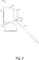
- Fig. 2 illustrates an example right elevational view 200 of the electronic device from Fig. 1 .
- Fig. 3 illustrates a front elevational view 300 of the electronic device from Fig. 1 .
- Fig. 4 illustrates a section view 400 of the electronic device from Fig. 3 , taken along line 4-4.
- the electronic device 100 may use a voice-activated virtual assistant.
- the electronic device 100 may connect to the Internet 104 ( e.g., through a wireless router) and support a variety of functions, including capturing audio and/or video data (including images or streaming video), transmitting the captured data to online storage, storing the captured data to local memory, streaming audio (e.g., music, news, podcasts, sports), and interacting with a virtual assistant to perform tasks (e . g ., search the internet, schedule events and alarms, control home automation, control internet-of-things (IoT) devices), and so on.
- tasks e . g ., search the internet, schedule events and alarms, control home automation, control internet-of-things (IoT) devices
- the electronic device 100 includes a housing formed by one or more housing members, including a front housing member 106 (e.g., a front cover) and a rear housing member 108 ( e.g., a head housing), a structural midframe 110 (also referred to as the midframe 110), a camera subassembly 112, and multiple printed circuit boards (PCBs) including at least a main logic board (MLB) 114, a camera board 116, and an infrared (IR) board 118. Additional PCBs may also be used.
- a front housing member 106 e.g., a front cover
- a rear housing member 108 e.g., a head housing
- a structural midframe 110 also referred to as the midframe 110
- a camera subassembly 112 e.g., a camera subassembly
- PCBs printed circuit boards
- MBB main logic board
- IR infrared
- the PCBs may include various integrated circuit (IC) components, including system-on-chip (SoC) IC devices, processors, and IC components for light-emitting diode(s) (LEDs), microphone(s), or sensors for detecting input such as touch-input, a button-press, or a voice command.
- the electronic device 100 also includes a heatsink 120, a speaker module 122, and a cable 124 ( e . g ., power cable).
- the electronic device 100 may also include a stand assembly 126.
- the electronic device 100 may include a hinge, such as a generally spherical ball joint formed by a stem 128 (e.g., ball stem), a bracket 130 (e.g., ball stem bracket) and a boot 132 ( e.g., ball stem boot).
- the bracket 130 is mounted to the midframe 110 to secure the boot 132 and the stem 128 in place.
- the electronic device 100 may further include removable assembly components, such as fasteners 134 ( e . g ., screws, bolts, adhesive, pressure-sensitive adhesive (PSA)).
- the electronic device 100 may include one or more additional thermal-control components (e . g ., heat spreader 136, thermal interface materials (TIMs) such as thermal gel, thermal paste, thermal adhesive, thermal tape) with high thermal conductivities.
- TIMs thermal interface materials
- the housing members 106 and 108 may include a plastic material and be formed, for example, using plastic-injection molding techniques.
- the housing members 106 and 108 may include any suitable geometry, including the example geometry illustrated in Fig. 1 .
- the rear housing member 108 may form a shell 138 ( e.g., a hollow cylinder or generally cylindrical shell) with a cap 140 ( e.g., a generally spherical cap) at one end of the cylinder.
- An example profile view of the rear housing member 108 is shown in Fig. 2 , which illustrates a tapering diameter of the shell 138 that is capped at the back end by the cap 140. This leaves an opposing end of the shell 138 open.
- the rear housing member 108 forms a general cup shape with an open end and an opposing, rounded, closed end.
- the examples described herein illustrate a generally cylindrical shell and a generally spherical cap, alternate shapes may also be implemented for the shell and cap.
- the rear housing member 108 may form an oblong shell or any other suitably-shaped shell, with a cross-section having any suitable shape, including an oval shape, a square shape, a rectangular shape, a triangular shape, or an asymmetrical shape.
- the rear housing member 108 defines a cavity for housing various components of the electronic device 100.
- the rear housing member 108 is a single, solid part, which is smooth (seamless), and cosmetically designed, but also enables manufacturing at low cost.
- the rear housing member 108 may include multiple parts assembled together.
- the front housing member 106 may form a general disk-shaped object that covers the open end (front) of the shell.
- the front housing member 106 may assemble to the midframe 110 via any suitable fastener or combination of fasteners, including PSA, one or more clips or snaps, screws, bolts, and so forth.
- the front housing member 106 may also include an aperture or transparent region that is aligned with the camera subassembly 112 to enable the camera subassembly 112 to view through the aperture or transparent region and capture images or video of a scene.
- the structural midframe 110 is configured to be slidably inserted into the rear housing member 108 and form a structural frame for the electronic device 100.
- the structural midframe 110 is formed such that a majority of the internal components of the electronic device 100 are assembled to the midframe 110, rather than to the housing.
- the internal components of the electronic device 100 can be assembled to the midframe 110 to create a midframe subassembly outside of the housing. This midframe subassembly can be tested prior to enclosing the assembled components within the housing, which allows modifications, adjustments, and repairs to be performed without risking damage to the housing via disassembly. Because the majority of the components of the electronic device 100 are assembled ( e .
- the housing can be formed with a geometry that can be molded cosmetically at low cost.
- the midframe 110 may be formed using any suitable technique, such as injection molding using any suitable material, such as a polycarbonate material (e . g ., 75% post-consumer recyclable polycarbonate, 95% post-consumer recyclable polycarbonate) or other thermoplastic polymer.
- the midframe 110 may also include a region forming a portion of a hinge. For example, and as discussed further herein, the region may include an inverse of a generally spherical ball joint.
- the camera subassembly 112 may capture images within a field of view of the electronic device 100 and may be mounted to the midframe 110.
- the camera subassembly 112 may be concentrically mounted to the midframe 110 such that the camera subassembly 112 is positioned within a perimeter of the midframe 110 and is positioned coaxially or shares a center axis ( e . g ., axis 402) with the midframe 110.
- the camera subassembly 112 may be mounted to a first side of the camera board 116, which is opposite a second side of the camera board 116 to which the main logic board 114 may be electrically connected.
- the heat spreader 136 may be positioned between the camera board 116 and the main logic board 114. As illustrated in Fig. 4 , the camera subassembly 112 is positioned proximate to a front of the electronic device 100 and may abut the front housing member 106, which includes an aperture or transparent portion aligned with the camera subassembly 112 to enable the camera subassembly 112 to capture images and/or video of a scene within its field of view.
- the PCBs (e.g., the main logic board 114, the camera board 116, the IR board 118) shown in Fig. 1 may be formed, for example, from glass-reinforced epoxy material such as FR4.
- the PCBs may include a single layer of electrically conductive traces and be a single-layer board.
- the PCBs may be a multi-layer board that includes multiple layers of electrically conductive traces that are separated by layers of a dielectric material.
- each of the PCBs may be mounted to the midframe 110, either directly or indirectly (e.g., mounted to another component that is assembled to the midframe). Accordingly, the PCBs are mounted to the midframe 110 and not mounted to the housing. In the example shown in Fig. 1 , each of the PCBs is to be mounted directly to the midframe 110.
- the main logic board 114 may be assembled to the midframe 110 proximate to a rear opening of the midframe 110 that opens toward a rear of the electronic device 100 ( e . g ., proximate to the cap 140 of the rear housing member 108).
- the main logic board 114 may be positioned between the heatsink 120 and the midframe 110.
- the main logic board 114 may be positioned between the heatsink 120 and the heat spreader 136.
- the main logic board 114 may be electrically connected to the camera board 116, e.g., via a flexible printed circuit (FPC) 142 and separated from the camera board 116 by the heat spreader 136.
- FPC flexible printed circuit
- the camera board 116 may be assembled to the midframe 110 proximate to the rear opening of the midframe 110 and within an interior of the midframe 110.
- the camera board 116 may be connected to the camera subassembly 112.
- the camera board 116 may be electrically connected to the IR board 118, e.g., via a flexible flat cable (FFC) 144.
- the camera board 116 may be positioned between the camera subassembly 112 and the main logic board 114. Also, the camera board 116 may be positioned between the heat spreader 136 and the midframe 110.
- the IR board 118 may be assembled to the midframe 110 and include circuitry to manage various functionality, including motion detection within the field of view of the electronic device 100 and/or facial detection of a face in the field of view.
- the IR board 118 may be mounted to the midframe 110 using one or more fasteners, including screws.
- the IR board 118 may be electrically connected to an IR illuminator and IR sensor, which may be usable for the motion detection or the facial recognition.
- the IR board 118 may be mounted proximate to a front opening of the midframe 110 that is open toward a front of the electronic device 100 (e.g., proximate to the front housing member 106) such that the camera board 116 is between the IR board 118 and the heat spreader 136.
- the heatsink 120 and the heat spreader 136 may be implemented to transfer and spread energy from heat-dissipating components on the PCBs, including SoC IC devices, memory devices, processors, and so forth.
- the heat spreader 136 may be positioned between the main logic board 114 and the camera board 116 to transfer and spread heat generated by one or more heat-generating IC components (e . g ., SoC IC component, memory IC components, audio amplifiers, and audio inductors) on the main logic board 114 and/or on the camera board 116.
- the heatsink 120 may be positioned on an opposing side of the main logic board 114 from the midframe 110 to transfer and spread heat generated by one or more heat-generating IC components on the main logic board 114 toward a back end and lateral sides of the electronic device 100.
- the main logic board 116 may include a shielding cover that shields IC components mounted on the main logic board 116.
- the shielding cover may be mounted on a first side of the main logic board 116 that is opposite a second side that faces the heat spreader 136.
- Thermal interface material may be dispensed onto the shielding cover to distribute heat generated by the IC components on the main logic board 116 to the heatsink 120.
- the speaker module 122 may be assembled to the heatsink 120 and positioned such that the heatsink 120 is between the speaker module 122 and the midframe 110. In this way, the speaker module 122 may output audio waves toward a back side of the electronic device 100 ( e . g ., toward the cap 140 of the rear housing member 108).
- the cap 140 of the rear housing member 108 may include one or more holes 404 ( e . g ., perforations) aligned with the speaker module 122 to provide a path for the audio waves to exit the housing.
- the speaker module 112 may be electrically connected to the main logic board 114 via one or more wires passing through or around the heatsink 120.
- the cable 124 may be assembled to the main logic board 114. As illustrated in Fig. 2 , the cable 124 may be positioned to longitudinally extend through a hole in the rear housing member 108, such as a hole 202 in the cap 140. Returning to Fig. 1 , the cable 124 may be assembled with a clip 146, which resists longitudinal movement of the cable 124 through the hole 202 in the rear housing member 108 from within the cavity toward the outside of the rear housing member 108. During assembly, for example, a portion of the cable 124 may be inserted through the hole 202 in the rear housing member 108 from outside of the rear housing member 108 and into the cavity.
- the cable 124 is overextended through the hole 202 and also through the open end of the rear housing member 108 to enable assembly of the cable 124 to the main logic board 114 outside of the rear housing member 108 ( e.g., beyond the open end of the rear housing member 108). Subsequent to assembling the cable 124 to the main logic board 114, which is assembled to the midframe 110, the cable 124 is moved in the opposite direction through the hole 202 to partially exit the cavity.
- the clip 146 retains a portion of the cable 124 in the cavity by preventing the cable 124 from exiting the rear housing member 108 beyond a location at which the clip 146 engages the cable 124.
- the rear housing member may include an additional hole (e.g., hole 148), which may allow the stem 128 of the hinge to extend through to the stand assembly 126.
- the stand assembly 126 may include a variety of components assembled together to support the electronic device 100.
- the stand assembly 126 may be connected to the stem 128 of the hinge.
- the stem 128 includes a shaft portion 406 and a head portion 408 ( e . g ., sphere).
- the shaft portion 406 is inserted through a hole 410 in the rear housing member 108 and the head portion 408 is positioned between the midframe 110, the boot 132, the bracket 130, and the rear housing member 108.
- the stand assembly 126 includes a base 412 that may be mounted to any suitable surface, such as a wall, a table, or a ceiling to support the electronic device 100. Further, the stand assembly 126 may be removably connected to the stem 128 of the hinge.
- Figs. 5-9 illustrate various views of the midframe 110 from Fig. 1 , in accordance with one or more aspects.
- Fig. 5 illustrates a front-right isometric view 500 of the example midframe 110 from Fig. 1 .
- Fig. 6 illustrates a front elevational view of the midframe from Fig. 5 .
- Fig. 7 illustrates a rear-left isometric view of the example midframe from Fig. 1 .
- Fig. 8 illustrates a rear elevational view of the midframe from Fig. 7 .
- Fig. 9 illustrates a left elevational view of the example midframe from Fig. 7 .
- the structural midframe 110 is generally ring-shaped, forming a generally cylindrical shape defining a cavity 502, and having a central axis (e.g., center axis 402), a first opening 504 (front opening) at a first end 506, and a second opening 508 (rear opening, also shown in Fig. 7 ) at a second end 510.
- the midframe 110 includes an inner surface 512 and an opposing outer surface 514.
- the inner surface 512 may substantially correspond to an inner diameter of the midframe 110.
- the outer surface 514 may substantially correspond to an outer diameter of the midframe 110.
- the inner and outer diameters may not be constant around the center axis 402.
- the midframe 110 includes a variety of features usable to assemble various features of the electronic device described with respect to Figs. 1-4 .
- the midframe 110 may include a plurality of screw holes 516 for receiving screws or bolts.
- the screw holes 516 may be substantially parallel to the center axis 402.
- One or more screw holes 516 may be located between the inner surface 512 and the outer surface 514 of the midframe 110.
- one or more screw holes 516 may be located on an extending member (e.g., flange) that extends from the inner surface 512 of the midframe 110 toward the center axis 402.
- the midframe 110 may also include a plurality of protrusions 518 (e.g., pins, pegs, rods) used to align components assembled to the midframe 110, including the PCBs ( e.g., the main logic board 114, the camera board 116, the IR board 118), the heat spreader 136, and the heatsink 120.
- the protrusions 518 may longitudinally extend in a direction that is substantially parallel with the center axis 402.
- One or more protrusions 518 e . g ., protrusion 518-1) may extend outwardly from the first end 506 of the midframe 110 and one or more additional protrusions 518 ( e .
- protrusion 518-2 may extend outwardly from the second end 510 of the midframe 110. At least some of the protrusions 518 may be located between the inner surface 512 and the outer surface 514 of the midframe 110. In some aspects, at least some of the protrusions 518 may be located on a flange that extends from the inner surface 512 of the midframe 110 toward the center axis 402.
- the midframe 110 may include one or more snap features 520 that are configured to mate with corresponding snap features on another component, such as the front housing member 106 in Fig. 1 .
- the snap features 520 may be positioned on the inner surface 512 of the midframe 110, such that the snap features 520 extend from the inner surface 512 toward the center axis 402 of the midframe 110.
- the snap features 520 may be positioned on the inner surface 512 of the midframe on opposing sides of the cavity 502 defined by the midframe 110.
- the first end 506 of the midframe 110 may include one or more substantially planar surfaces, such as first surface 522-1 and second surface 522-2.
- the first and second surfaces 522-1 and 522-2 may be coplanar with one another.
- the first surface 522-1 may define a plane that is substantially parallel to a plane defined by the second surface 522-2.
- the plane defined by each of the first and second surfaces 522-1 and 522-2, respectively may be substantially orthogonal to the center axis 402 of the midframe.
- Each of the first and second surfaces 522-1 and 522-2 are configured to interface with a bonding material, such as PSA, which may bond the respective surface to the front housing member 106.
- the front housing member 106 may include one or more ribs or flanges that extend into the cavity 502 defined by the midframe 110, where the ribs or flanges include snap features that mate with the snap features 520 on the midframe, creating thermal-exchange surfaces between the front housing member 106 and the midframe 110.
- the midframe 110 may also include a hinge-bearing surface 524.
- the hinge-bearing surface 524 may include a concave surface forming an inverse of a portion of sphere that is truncated to form a substantial C-shape. In this way, the hinge-bearing surface 524 may interface with a ball stem (e.g., the stem 128 illustrated in Fig. 1 ) of a generally spherical ball joint.
- the hinge-bearing surface 524 provides a low-friction surface that abuts the sphere of the ball stem to (i) enable the electronic device 100 to tilt relative to the stand assembly 126 based on a force applied by a user and (ii) support the electronic device 100 in a tilted orientation relative to the stand assembly 126.
- the hinge-bearing surface 524 provides such friction and support without lubricant.
- the hinge-bearing surface 524 may include any suitable material, including polycarbonate, nylon, or other low-friction material.
- the hinge-bearing surface 524 forms an edge 526 with the outer surface of the midframe 110, where the edge 526 forms a partial circle that is open to receive a shaft portion 406 of the stem 128 of the ball joint.
- the stem 128 can be inserted through the open portion of the edge 526 of the hinge-bearing surface 524 and "snap" into place, enabling the hinge-bearing surface 524 to abut the sphere of the stem 128.
- the midframe 110 may include one or more ribs 528 (e.g., rib 528-1, rib 528-2) located proximate to the hinge-bearing surface 524.
- the ribs 528 are configured to interface with mating ribs on the boot 132 shown in Fig. 1 .
- the ribs 528 longitudinally extend transversely between the outer surface 514 and the inner surface 512. In the example illustrated in Fig. 6 , the ribs 528 extend in a direction that is generally orthogonal to the center axis 402 and generally parallel to a central axis ( e.g., axis 602) of the hinge-bearing surface 524.
- the ribs 528 may extend in a direction that is non-orthogonal to the center axis 402.
- Each of the ribs 528 may include a longitudinal axis 530 (e.g., the rib 528-1 includes longitudinal axis 604-1, the rib 528-2 includes longitudinal axis 604-2).
- the longitudinal axis 604-1 of the rib 528-1 may not intersect the center axis 402 of the midframe 110.
- the longitudinal axis 604-2 of the rib 528-2 may not intersect the center axis 402 of the midframe.
- the ribs 528 are substantially parallel to one another and are positioned proximate to the first end 506 of the midframe 110 on opposing sides of the hinge-bearing surface 524 ( e.g., the hinge-bearing surface 524 is positioned between the ribs 528).
- the ribs 528 support control of a friction feeling of the hinge because the ribs 528 help secure the position of the boot 132. From a user perspective, this implementation helps the hinge "feel" more stable.
- the ribs 528 reduce negative effects of strain applied to the boot 132 when rotating the hinge, as compared to using holes or pins to assemble the boot 132 to the midframe 110.
- the ribs 528 are arranged to resist movement of the boot 132 relative to the midframe 110, which may result from friction forces acting on the boot 132 during three-dimensional (3D) rotational movement of the midframe 110 relative to the stem 128 of the ball joint.
- the midframe 110 may also include a crossbeam 606 that provides structural support and rigidity to the midframe 110, particularly proximate to the hinge-bearing surface 524.
- the crossbeam 606 longitudinally extends transversely from one region (e.g., a first region) of the inner surface 512 to another region ( e.g., a second region) of the inner surface 512, across a portion of the cavity 502 defined by the midframe 110.
- the crossbeam 606 may be positioned substantially orthogonal to the center axis 402 of the midframe 110.
- the crossbeam 606 is located proximate to the second end 510 of the midframe 110 (as illustrated in Fig.
- the crossbeam 606 reduces stress applied to PSA assembled to the midframe 110 on the first and second surfaces 522-1 and 522-2 when the 110 and the components assembled onto the midframe 110 are inserted into the rear housing member 108.
- the midframe 110 may include alignment guides, such as alignment guide 608.
- the alignment guide 608 may include any suitable guide, including a slot, channel, track, rib, protrusion, or sleeve, which can interface or mate with an opposing slot, channel, track, rib, protrusion, or sleeve on the rear housing member 108 to align the midframe 110 relative to the rear housing member 108 for assembly.
- the outer surface 514 of the midframe 110 includes a substantially planar region 610.
- the planar region 610 may be located on a circumference of the midframe 110, such that the planar region 610 faces an interior surface (not shown in Fig. 6 ) of the rear housing member 108.
- the planar region 610 may be located between two or more protrusions ( e . g ., alignment protrusions 612), which are usable as alignment features to align an antenna (not shown) with the midframe 110 for assembly. Accordingly, the planar region 610 may also be referred to as an antenna region.
- the antenna may include any suitable antenna, including a wireless-network antenna mounted on a flexible printed circuit board, which may be electrically connected to the camera board 116.
- the planar region 610 may reduce strain on certain features of the antenna, such as solder joints (e.g., solder joints connecting a coaxial cable to the antenna).
- the antenna may be a Wi-Fi antenna configured to enable access to a wireless network, e . g ., using 2.4 GHz and/or 5 GHz bands, 802.11 standards.
- the antenna By assembling the antenna onto the midframe 110, testing can be performed during the assembly process prior to inserting the assembly into the cavity of the rear housing member 108.
- Conventional devices that assemble the antenna to the housing have a likelihood of damaging the antenna when inserting other components into the housing.
- the likelihood of damaging the antenna when inserting the assembled components into the rear housing member 108 is reduced.
- the antenna may also be sensitive in terms of its proximity to other metals.
- alignment features e . g ., the substantially planar region 610, the alignment protrusions 612
- Fig. 7 illustrates a rear-left isometric view 700 of the example midframe from Fig. 1 .
- This view 700 illustrates a view of the second end 510 of the midframe 110, including the second opening 508 and the crossbeam 606.
- the substantially planar region 610 e . g ., antenna region
- the alignment protrusions 612 usable for mounting a flexible printed circuit board having the antenna.
- Fig. 8 illustrates a rear elevational view 800 of the midframe from Fig. 7 .
- the view 800 illustrates a view of the second end 510 of the midframe 110.
- the midframe 110 includes multiple extending members 802 that extend from the inner surface 512 of the midframe 110 and into the cavity 502 defined by the midframe 110.
- the extending members 802 extend toward the center axis 402 of the midframe.
- the extending members 802 may include one or more protrusions ( e . g ., protrusions 518) or holes 804 for aligning components, such as the PCBs, with the midframe 110.
- the planar region 610 and the alignment protrusions 612 provide an antenna region that, in the illustrated orientation of the midframe 110, is on a lower portion of the midframe 110.
- the lower region e.g., bottom half
- the antenna region may be implemented at any suitable location along the perimeter (on the outer surface 514) of the midframe 110 and is not limited to the location illustrated in the figures.
- Fig. 9 illustrates a left elevational view 900 of the example midframe 110 from Fig. 7 .
- the view 900 illustrates a side view of the midframe 110, with the first end 506 on the left and the second end 510 on the right.
- the substantially planar region 610 and alignment protrusions 612 are located on the outer surface 514 of the midframe 110.
- Figs. 10 and 11 depict methods 1000 and 1100, which are shown as a set of blocks that specify operations performed but are not necessarily limited to the order or combinations shown for performing the operations by the respective blocks. Further, any of one or more of the operations may be repeated, combined, reorganized, or linked to provide a wide array of additional and/or alternate methods.
- Fig. 10 depicts a method 1000 for assembly of a midframe subassembly.
- Fig. 11 depicts a method 1100 for a main assembly, which is continued from the method 1000 of Fig. 10 .
- a camera subassembly is mounted onto a camera board.
- the camera subassembly 112 may be mounted to a first side of the camera board 116.
- the camera board 116 is mounted to the midframe 110 such that the first side of the camera board 116 faces an interior of the midframe 110.
- a thermal interface material is dispensed onto the camera board of the camera subassembly.
- the thermal interface material may include thermal gel, thermal paste, thermal adhesive, thermal tape, and so forth.
- a heat spreader is mounted onto the midframe.
- the heat spreader 136 may be mounted onto the midframe 110 using one or more fasteners 134, such as screws.
- the heat spreader 136 may be mounted to the midframe 110 to cause the camera board 116 to be positioned between the heat spreader 136 and the midframe 110.
- an antenna is mounted onto the midframe.
- the antenna may be a wireless-network antenna mounted on a flexible printed circuit board.
- the flexible printed circuit board may be mounted onto an antenna region, such as the planar region 610 of the midframe, and aligned with the midframe 110 using the alignment protrusions 612.
- the antenna is electrically connected to the camera board.
- the antenna may be connected to the camera board 116 via a flexible cable.
- the camera board is connected to an IR board.
- the camera board 116 may be electrically connected to the IR board 118 via the FFC 144.
- the IR board is mounted to the midframe.
- the IR board 118 may be mounted to the midframe 110 using, for example, one or more fasteners 134 (e.g., screws).
- the IR board 118 is mounted proximate to a front opening of the midframe 110 to cause the camera board 116 to be positioned between the IR board 118 and the heat spreader 136.
- the camera board is electrically connected to an MLB.
- the camera board 116 may be electrically connected to the MLB 114 via the FPC 142 and separated from the MLB 116 by the heat spreader 136.
- the MLB is mounted to the midframe.
- the MLB 114 may be mounted to the midframe 110 proximate to a rear opening of the midframe 110 such that the heat spreader 136 is positioned between the MLB 114 and the camera board 116.
- thermal interface material is dispensed onto a shielding cover on the MLB.
- a thermal gel or other thermal interface material may be dispensed onto the shielding cover located on a first side of the MLB 114 that is opposite a second side of the MLB 114 that faces the heat spreader 136.
- the power cable is inserted through the rear housing member.
- the cable 124 may be inserted and overextended through the hole 202 in the rear housing member 108 from the exterior of the rear housing member 108 toward the interior of the rear housing member 108.
- a clip is installed onto the power cable.
- the clip 146 may be assembled to the cable 124 to resist longitudinal movement of the cable 124 through the hole 202 in the rear housing member 108 from within the cavity toward the outside of the rear housing member 108.
- the power cable is connected to the MLB.
- a speaker module is electrically connected to the MLB.
- the speaker module 122 may be electrically connected to the main logic board 114 via one or more wires passing through or around the heatsink 120.
- a heatsink subassembly with the speaker module is mounted to the midframe.
- the heatsink 120 may be mounted to the midframe 110 on an opposing side of the MLB 114 from the midframe 110 using one or more fasteners 134 ( e . g ., screws).
- the midframe subassembly is mounted to an interior of the rear housing member.
- the midframe subassembly which includes at least the midframe 110 the components mounted to the midframe 110 (e.g., the camera board 116, the IR board 118, the heat spreader 136, the MLB 114, and the heatsink 120, which includes the speaker module 122) may be inserted into the cavity defined by the rear housing member 108 and secured within the rear housing member 108 using one or more fasteners 134 ( e . g ., screws).
- a stem of a hinge is installed onto the midframe.
- the stem 128 of the hinge may include a shaft portion 406 and a head portion 408, where the shaft portion 406 is inserted into the hole 148 of the rear housing member 108 and the head portion 408 is seated onto the hinge-bearing surface 524 of the midframe 110.
- a boot is installed onto the stem.
- the boot 132 may be positioned to interface with the sphere of the stem 128 and the midframe 110, which includes the ribs 528 on opposing sides of the hinge-bearing surface 524 to secure the position of the boot 132.
- a bracket for the hinge is mounted onto the midframe.
- the bracket 130 is mounted to the midframe 110 to secure the boot 132 and the stem 128 in place, while allowing rotational movement of the sphere of the stem 128.
- a front housing member is mounted onto the midframe.
- the front housing member 106 may be mounted to the midframe 110 via the snap features 520 and one or more fasteners 134, such as PSA.
- the architecture of the electronic device as disclosed in the above decribed embodiments is such that the majority of internal components of the electronic device can be assembled onto the structural midframe to form a midframe subassembly outside of the housing and the housing can be assembled onto the electronic device last.
- This enables the housing to maintain a simple geometry (with less mounting features), which in turn enables the housing to be a cheaper, more environmentally-friendly, as-molded cosmetic part (without requiring paint to achieve a desired gloss level or cover molding imperfections).
- fewer components may be fixed to the housing, which increases the reworkability of the electronic device. Because the housing ( e .
- the midframe subassembly e . g ., cosmetic enclosure
- additional testing may be performed on the midframe subassembly ( e . g ., assembled components and modules) prior to assembling the housing. If some failure or fallout occurs during the assembly process, the techniques herein enable an operator to make the appropriate repairs or adjustments, rather than disassemble the electronic device and risk damaging the housing.
Landscapes
- Engineering & Computer Science (AREA)
- General Engineering & Computer Science (AREA)
- Mechanical Engineering (AREA)
- Physics & Mathematics (AREA)
- Signal Processing (AREA)
- Multimedia (AREA)
- General Physics & Mathematics (AREA)
- Microelectronics & Electronic Packaging (AREA)
- Electromagnetism (AREA)
- Thermal Sciences (AREA)
- Studio Devices (AREA)
- Accessories Of Cameras (AREA)
- Telephone Set Structure (AREA)
Abstract
Description
- As technology evolves, maintaining a low cost of production of an electronic device may be challenging. In some cases, reducing the production cost may include reducing the complexity of a device's components and/or the number of steps used in the assembly process. Some devices with a small form factor have limited available space within a housing for operators and tools to assemble internal components. Consequently, there may be insufficient clearance for the operator or tool to easily access areas within the housing to fasten components together. One solution is to fix multiple internal components to the housing; however, using the housing as a structural member may result in a more-complex housing geometry and, in some cases, a device that is difficult to rework.
- The present document describes an electronic device with a (structural) midframe and associated methods. The proposed solution is defined by the accompanying independent claims. Potential embodiments are in particular defined by the dependent claims.
- In an example embodiment, the architectural design of the electronic device (e.g., a security camera) may be such that its components are assembled onto the midframe to form a midframe subassembly and the midframe subassembly may then be placed in a portion of the housing. The midframe may include various features that enable multiple printed circuit boards, a camera subassembly, a front housing member, a heatsink, and a heat spreader to be assembled onto the midframe outside of the housing. The midframe can also include a hinge-bearing surface forming a portion of a ball joint for supporting rotational movement of the electronic device. Accordingly, the electronic device can use the midframe, rather than the housing, as a structural member.
- Generally, using a midframe as described herein can allow the majority of internal components of the electronic device to be assembled onto the midframe to form a midframe subassembly outside of the housing, wherein the housing can be assembled onto the electronic device last. This enables the housing to maintain a simple geometry (with less mounting features), which in turn enables the housing to be a cheaper, more environmentally-friendly, as-molded cosmetic part (without requiring paint to achieve a desired gloss level or cover molding imperfections). Further, by using a midframe as claimed, fewer components may be fixed to the housing, which increases the reworkability of the electronic device. Because the housing (e.g., cosmetic enclosure) may be assembled after a midframe subassembly, additional testing may be performed on the midframe subassembly (e.g., assembled components and modules) prior to assembling the housing. If some failure or fallout occurs during the assembly process, an operator may make the appropriate repairs or adjustments more easily avoiding disassembly of the electronic device and reducing the risk of damaging the housing.
- In some aspects, an electronic device is disclosed. The electronic device may include a housing member, a midframe, and a plurality of components assembled onto the midframe. The housing member may form a shell with a cap. The midframe may define an aperture and form a structural frame for the electronic device. The midframe may also be positioned within the housing member in an orientation that is substantially coaxial with the housing member. The plurality of components may include a wireless-network antenna assembled onto an outer surface of the midframe, a camera subassembly assembled onto the midframe and positioned coaxially with the midframe, one or more printed circuit boards assembled onto the midframe, and a speaker module assembled onto the midframe.
- In other aspects, a (structural) midframe for an electronic device is disclosed. The midframe includes a shape defining an aperture and configured to be slidably inserted into a housing member forming a shell. The midframe also includes an inner surface associated with an inner diameter and an outer surface associated with an outer diameter. In addition, the midframe includes an antenna region located on the outer surface, where the antenna region includes a substantially planar region and at least two alignment protrusions for aligning a flexible printed circuit board having an antenna that is configured to be assembled onto the midframe. The midframe further includes a plurality of features for assembling a plurality of printed circuit boards, one or more heat spreaders, and one or more heatsinks onto the midframe. Also, the midframe includes a plurality of snap features positioned on the inner surface, where the plurality of snap features are configured to mate with corresponding snap features on a front housing member to enable assembly of the front housing member to the midframe. Additionally, the midframe includes a hinge-bearing surface, a crossbeam, and first and second ribs. The hinge-bearing surface may have a concave surface forming an inverse of a portion of a sphere and may be configured to interface with a sphere of a ball joint. The crossbeam may be positioned to longitudinally extend transversely across the aperture from a first region of the inner surface to a second region of the inner surface. Further, the crossbeam may be located proximate to the hinge-bearing surface. The first and second ribs may longitudinally extend transversely between the outer surface and the inner surface. Also, the first and second ribs may be positioned on opposing sides of the hinge-bearing surface and configured to interface with mating ribs on a boot of the ball joint.
- In other aspects, a method relating to assembly of an electronic device is disclosed. The method includes mounting a camera subassembly onto a camera board and mounting the camera board onto a midframe that forms a structural frame for the electronic device, where the camera board is mounted to be coaxial with the midframe. In addition, the method includes mounting a heat spreader onto the midframe to cause the camera board to be positioned between the heat spreader and the midframe. The method also includes mounting an antenna onto an outer surface of the midframe. The method further includes electrically connecting the camera board to an infrared board and mounting the infrared board onto the midframe to cause the camera board to be positioned between the infrared board and the heat spreader. Additionally, the method includes electrically connecting the camera board to a main logic board and mounting the main logic board onto the midframe to provide the midframe subassembly.
- This summary is provided to introduce simplified concepts of an electronic device with a structural midframe and associated methods, which is further described below in the Detailed Description. This summary is not intended to identify essential features of the claimed subject matter, nor is it intended for use in determining the scope of the claimed subject matter.
- The details of one or more aspects of an electronic device with a structural midframe and associated methods are described in this document with reference to the following drawings. The same numbers are used throughout the drawings to reference like features and components.
-
Fig. 1 illustrates an example electronic device and an exploded view of some components thereof. -
Fig. 2 illustrates an example right elevational view of the electronic device fromFig. 1 . -
Fig. 3 illustrates a front elevational view of the electronic device fromFig. 1 . -
Fig. 4 illustrates a section view of the electronic device fromFig. 3 , taken along line 4-4. -
Fig. 5 illustrates a front-right isometric view of the example midframe fromFig. 1 . -
Fig. 6 illustrates a front elevational view of the midframe fromFig. 5 . -
Fig. 7 illustrates a rear-left isometric view of the example midframe fromFig. 1 . -
Fig. 8 illustrates a rear elevational view of the midframe fromFig. 7 . -
Fig. 9 illustrates a left elevational view of the example midframe fromFig. 7 . -
Fig. 10 depicts a method for assembly of a midframe subassembly. -
Fig. 11 depicts a method for a main assembly, which is continued fromFig. 10 . - This document describes an electronic device with a structural midframe and associated methods.
- While features and concepts of the described electronic device with a structural midframe and associated methods can be implemented in any number of different environments, aspects are described in the context of the following examples.
-
Fig. 1 illustrates an example electronic device 100 (e.g., a security camera) and an explodedview 102 of some components thereof.Fig. 2 illustrates an example rightelevational view 200 of the electronic device fromFig. 1 .Fig. 3 illustrates a frontelevational view 300 of the electronic device fromFig. 1 .Fig. 4 illustrates asection view 400 of the electronic device fromFig. 3 , taken along line 4-4. In the following, reference may be made to various components or parts of theelectronic device 100 illustrated in any ofFigs. 1-4 . - The
electronic device 100, in some aspects, may use a voice-activated virtual assistant. Theelectronic device 100 may connect to the Internet 104 (e.g., through a wireless router) and support a variety of functions, including capturing audio and/or video data (including images or streaming video), transmitting the captured data to online storage, storing the captured data to local memory, streaming audio (e.g., music, news, podcasts, sports), and interacting with a virtual assistant to perform tasks (e.g., search the internet, schedule events and alarms, control home automation, control internet-of-things (IoT) devices), and so on. - The
electronic device 100 includes a housing formed by one or more housing members, including a front housing member 106 (e.g., a front cover) and a rear housing member 108 (e.g., a head housing), a structural midframe 110 (also referred to as the midframe 110), acamera subassembly 112, and multiple printed circuit boards (PCBs) including at least a main logic board (MLB) 114, acamera board 116, and an infrared (IR)board 118. Additional PCBs may also be used. The PCBs may include various integrated circuit (IC) components, including system-on-chip (SoC) IC devices, processors, and IC components for light-emitting diode(s) (LEDs), microphone(s), or sensors for detecting input such as touch-input, a button-press, or a voice command. Theelectronic device 100 also includes aheatsink 120, aspeaker module 122, and a cable 124 (e.g., power cable). Theelectronic device 100 may also include astand assembly 126. In some aspects, theelectronic device 100 may include a hinge, such as a generally spherical ball joint formed by a stem 128 (e.g., ball stem), a bracket 130 (e.g., ball stem bracket) and a boot 132 (e.g., ball stem boot). Thebracket 130 is mounted to the midframe 110 to secure theboot 132 and thestem 128 in place. Theelectronic device 100 may further include removable assembly components, such as fasteners 134 (e.g., screws, bolts, adhesive, pressure-sensitive adhesive (PSA)). Along with theheatsink 120, theelectronic device 100 may include one or more additional thermal-control components (e.g.,heat spreader 136, thermal interface materials (TIMs) such as thermal gel, thermal paste, thermal adhesive, thermal tape) with high thermal conductivities. - The
housing members housing members Fig. 1 . For instance, therear housing member 108 may form a shell 138 (e.g., a hollow cylinder or generally cylindrical shell) with a cap 140 (e.g., a generally spherical cap) at one end of the cylinder. An example profile view of therear housing member 108 is shown inFig. 2 , which illustrates a tapering diameter of theshell 138 that is capped at the back end by thecap 140. This leaves an opposing end of theshell 138 open. In this way, therear housing member 108 forms a general cup shape with an open end and an opposing, rounded, closed end. Although the examples described herein illustrate a generally cylindrical shell and a generally spherical cap, alternate shapes may also be implemented for the shell and cap. For example, therear housing member 108 may form an oblong shell or any other suitably-shaped shell, with a cross-section having any suitable shape, including an oval shape, a square shape, a rectangular shape, a triangular shape, or an asymmetrical shape. - The
rear housing member 108 defines a cavity for housing various components of theelectronic device 100. In the illustrated example, therear housing member 108 is a single, solid part, which is smooth (seamless), and cosmetically designed, but also enables manufacturing at low cost. Alternatively, therear housing member 108 may include multiple parts assembled together. Thefront housing member 106 may form a general disk-shaped object that covers the open end (front) of the shell. Thefront housing member 106 may assemble to themidframe 110 via any suitable fastener or combination of fasteners, including PSA, one or more clips or snaps, screws, bolts, and so forth. Thefront housing member 106 may also include an aperture or transparent region that is aligned with thecamera subassembly 112 to enable thecamera subassembly 112 to view through the aperture or transparent region and capture images or video of a scene. - The
structural midframe 110 is configured to be slidably inserted into therear housing member 108 and form a structural frame for theelectronic device 100. In aspects, thestructural midframe 110 is formed such that a majority of the internal components of theelectronic device 100 are assembled to themidframe 110, rather than to the housing. The internal components of theelectronic device 100 can be assembled to the midframe 110 to create a midframe subassembly outside of the housing. This midframe subassembly can be tested prior to enclosing the assembled components within the housing, which allows modifications, adjustments, and repairs to be performed without risking damage to the housing via disassembly. Because the majority of the components of theelectronic device 100 are assembled (e.g., mounted) to themidframe 110, the housing can be formed with a geometry that can be molded cosmetically at low cost. The midframe 110 may be formed using any suitable technique, such as injection molding using any suitable material, such as a polycarbonate material (e.g., 75% post-consumer recyclable polycarbonate, 95% post-consumer recyclable polycarbonate) or other thermoplastic polymer. The midframe 110 may also include a region forming a portion of a hinge. For example, and as discussed further herein, the region may include an inverse of a generally spherical ball joint. - Turning to
Fig. 4 , thecamera subassembly 112 may capture images within a field of view of theelectronic device 100 and may be mounted to themidframe 110. In some aspects, thecamera subassembly 112 may be concentrically mounted to the midframe 110 such that thecamera subassembly 112 is positioned within a perimeter of themidframe 110 and is positioned coaxially or shares a center axis (e.g., axis 402) with themidframe 110. Returning toFig. 1 , thecamera subassembly 112 may be mounted to a first side of thecamera board 116, which is opposite a second side of thecamera board 116 to which themain logic board 114 may be electrically connected. In some implementations, theheat spreader 136 may be positioned between thecamera board 116 and themain logic board 114. As illustrated inFig. 4 , thecamera subassembly 112 is positioned proximate to a front of theelectronic device 100 and may abut thefront housing member 106, which includes an aperture or transparent portion aligned with thecamera subassembly 112 to enable thecamera subassembly 112 to capture images and/or video of a scene within its field of view. - The PCBs (e.g., the
main logic board 114, thecamera board 116, the IR board 118) shown inFig. 1 may be formed, for example, from glass-reinforced epoxy material such as FR4. In some instances, the PCBs may include a single layer of electrically conductive traces and be a single-layer board. In other instances, the PCBs may be a multi-layer board that includes multiple layers of electrically conductive traces that are separated by layers of a dielectric material. As illustrated inFig. 4 , each of the PCBs may be mounted to themidframe 110, either directly or indirectly (e.g., mounted to another component that is assembled to the midframe). Accordingly, the PCBs are mounted to themidframe 110 and not mounted to the housing. In the example shown inFig. 1 , each of the PCBs is to be mounted directly to themidframe 110. - Returning to
Fig. 1 , themain logic board 114 may be assembled to the midframe 110 proximate to a rear opening of the midframe 110 that opens toward a rear of the electronic device 100 (e.g., proximate to thecap 140 of the rear housing member 108). In aspects, themain logic board 114 may be positioned between theheatsink 120 and themidframe 110. Also, themain logic board 114 may be positioned between theheatsink 120 and theheat spreader 136. Themain logic board 114 may be electrically connected to thecamera board 116, e.g., via a flexible printed circuit (FPC) 142 and separated from thecamera board 116 by theheat spreader 136. - The
camera board 116 may be assembled to the midframe 110 proximate to the rear opening of themidframe 110 and within an interior of themidframe 110. Thecamera board 116 may be connected to thecamera subassembly 112. In addition, thecamera board 116 may be electrically connected to theIR board 118, e.g., via a flexible flat cable (FFC) 144. Thecamera board 116 may be positioned between thecamera subassembly 112 and themain logic board 114. Also, thecamera board 116 may be positioned between theheat spreader 136 and themidframe 110. - The
IR board 118 may be assembled to themidframe 110 and include circuitry to manage various functionality, including motion detection within the field of view of theelectronic device 100 and/or facial detection of a face in the field of view. In an example, theIR board 118 may be mounted to the midframe 110 using one or more fasteners, including screws. TheIR board 118 may be electrically connected to an IR illuminator and IR sensor, which may be usable for the motion detection or the facial recognition. TheIR board 118 may be mounted proximate to a front opening of the midframe 110 that is open toward a front of the electronic device 100 (e.g., proximate to the front housing member 106) such that thecamera board 116 is between theIR board 118 and theheat spreader 136. - The
heatsink 120 and theheat spreader 136 may be implemented to transfer and spread energy from heat-dissipating components on the PCBs, including SoC IC devices, memory devices, processors, and so forth. Theheat spreader 136 may be positioned between themain logic board 114 and thecamera board 116 to transfer and spread heat generated by one or more heat-generating IC components (e.g., SoC IC component, memory IC components, audio amplifiers, and audio inductors) on themain logic board 114 and/or on thecamera board 116. Theheatsink 120 may be positioned on an opposing side of themain logic board 114 from the midframe 110 to transfer and spread heat generated by one or more heat-generating IC components on themain logic board 114 toward a back end and lateral sides of theelectronic device 100. Themain logic board 116 may include a shielding cover that shields IC components mounted on themain logic board 116. The shielding cover may be mounted on a first side of themain logic board 116 that is opposite a second side that faces theheat spreader 136. Thermal interface material may be dispensed onto the shielding cover to distribute heat generated by the IC components on themain logic board 116 to theheatsink 120. - The
speaker module 122 may be assembled to theheatsink 120 and positioned such that theheatsink 120 is between thespeaker module 122 and themidframe 110. In this way, thespeaker module 122 may output audio waves toward a back side of the electronic device 100 (e.g., toward thecap 140 of the rear housing member 108). Referring toFig. 4 , thecap 140 of therear housing member 108 may include one or more holes 404 (e.g., perforations) aligned with thespeaker module 122 to provide a path for the audio waves to exit the housing. Thespeaker module 112 may be electrically connected to themain logic board 114 via one or more wires passing through or around theheatsink 120. - Returning to
Fig. 1 , thecable 124 may be assembled to themain logic board 114. As illustrated inFig. 2 , thecable 124 may be positioned to longitudinally extend through a hole in therear housing member 108, such as ahole 202 in thecap 140. Returning toFig. 1 , thecable 124 may be assembled with aclip 146, which resists longitudinal movement of thecable 124 through thehole 202 in therear housing member 108 from within the cavity toward the outside of therear housing member 108. During assembly, for example, a portion of thecable 124 may be inserted through thehole 202 in therear housing member 108 from outside of therear housing member 108 and into the cavity. Thecable 124 is overextended through thehole 202 and also through the open end of therear housing member 108 to enable assembly of thecable 124 to themain logic board 114 outside of the rear housing member 108 (e.g., beyond the open end of the rear housing member 108). Subsequent to assembling thecable 124 to themain logic board 114, which is assembled to themidframe 110, thecable 124 is moved in the opposite direction through thehole 202 to partially exit the cavity. Theclip 146 retains a portion of thecable 124 in the cavity by preventing thecable 124 from exiting therear housing member 108 beyond a location at which theclip 146 engages thecable 124. The rear housing member may include an additional hole (e.g., hole 148), which may allow thestem 128 of the hinge to extend through to thestand assembly 126. - The
stand assembly 126 may include a variety of components assembled together to support theelectronic device 100. In the example illustrated inFig. 4 , thestand assembly 126 may be connected to thestem 128 of the hinge. Thestem 128 includes ashaft portion 406 and a head portion 408 (e.g., sphere). Theshaft portion 406 is inserted through a hole 410 in therear housing member 108 and thehead portion 408 is positioned between the midframe 110, theboot 132, thebracket 130, and therear housing member 108. Thestand assembly 126 includes a base 412 that may be mounted to any suitable surface, such as a wall, a table, or a ceiling to support theelectronic device 100. Further, thestand assembly 126 may be removably connected to thestem 128 of the hinge. -
Figs. 5-9 illustrate various views of the midframe 110 fromFig. 1 , in accordance with one or more aspects.Fig. 5 illustrates a front-rightisometric view 500 of theexample midframe 110 fromFig. 1 .Fig. 6 illustrates a front elevational view of the midframe fromFig. 5 .Fig. 7 illustrates a rear-left isometric view of the example midframe fromFig. 1 .Fig. 8 illustrates a rear elevational view of the midframe fromFig. 7 .Fig. 9 illustrates a left elevational view of the example midframe fromFig. 7 . - Referring to
Fig. 5 , thestructural midframe 110 is generally ring-shaped, forming a generally cylindrical shape defining acavity 502, and having a central axis (e.g., center axis 402), a first opening 504 (front opening) at afirst end 506, and a second opening 508 (rear opening, also shown inFig. 7 ) at asecond end 510. Themidframe 110 includes aninner surface 512 and an opposingouter surface 514. Theinner surface 512 may substantially correspond to an inner diameter of themidframe 110. Theouter surface 514 may substantially correspond to an outer diameter of themidframe 110. However, due to the various features implemented on themidframe 110, the inner and outer diameters may not be constant around thecenter axis 402. Themidframe 110 includes a variety of features usable to assemble various features of the electronic device described with respect toFigs. 1-4 . For example, themidframe 110 may include a plurality of screw holes 516 for receiving screws or bolts. The screw holes 516 may be substantially parallel to thecenter axis 402. One or more screw holes 516 may be located between theinner surface 512 and theouter surface 514 of themidframe 110. In some aspects, one or more screw holes 516 may be located on an extending member (e.g., flange) that extends from theinner surface 512 of the midframe 110 toward thecenter axis 402. - The midframe 110 may also include a plurality of protrusions 518 (e.g., pins, pegs, rods) used to align components assembled to the
midframe 110, including the PCBs (e.g., themain logic board 114, thecamera board 116, the IR board 118), theheat spreader 136, and theheatsink 120. Theprotrusions 518 may longitudinally extend in a direction that is substantially parallel with thecenter axis 402. One or more protrusions 518 (e.g., protrusion 518-1) may extend outwardly from thefirst end 506 of themidframe 110 and one or more additional protrusions 518 (e.g., protrusion 518-2) may extend outwardly from thesecond end 510 of themidframe 110. At least some of theprotrusions 518 may be located between theinner surface 512 and theouter surface 514 of themidframe 110. In some aspects, at least some of theprotrusions 518 may be located on a flange that extends from theinner surface 512 of the midframe 110 toward thecenter axis 402. - In addition, the
midframe 110 may include one or more snap features 520 that are configured to mate with corresponding snap features on another component, such as thefront housing member 106 inFig. 1 . The snap features 520 may be positioned on theinner surface 512 of themidframe 110, such that the snap features 520 extend from theinner surface 512 toward thecenter axis 402 of themidframe 110. As illustrated inFig. 6 , the snap features 520 may be positioned on theinner surface 512 of the midframe on opposing sides of thecavity 502 defined by themidframe 110. - Returning to
Fig. 5 , thefirst end 506 of the midframe 110 may include one or more substantially planar surfaces, such as first surface 522-1 and second surface 522-2. The first and second surfaces 522-1 and 522-2 may be coplanar with one another. Alternatively, the first surface 522-1 may define a plane that is substantially parallel to a plane defined by the second surface 522-2. In some aspects, the plane defined by each of the first and second surfaces 522-1 and 522-2, respectively, may be substantially orthogonal to thecenter axis 402 of the midframe. Each of the first and second surfaces 522-1 and 522-2 are configured to interface with a bonding material, such as PSA, which may bond the respective surface to thefront housing member 106. By using thefasteners 134, including the snap features 520 and the PSA, on themidframe 110, thefront housing member 106 may be assembled onto the midframe 110 rather than onto therear housing member 108. - Compared to conventional techniques that may assemble the
front housing member 106 to therear housing member 108, assembling thefront housing member 106 to themidframe 110 allows additional space in the assembly for thermal interface materials (e.g., heat spreaders, TIMs) for the camera, without enlarging therear housing member 108. Additional thermal-exchange surfaces are also included by mating thefront housing member 106 to themidframe 110. For example, thefront housing member 106 may include one or more ribs or flanges that extend into thecavity 502 defined by themidframe 110, where the ribs or flanges include snap features that mate with the snap features 520 on the midframe, creating thermal-exchange surfaces between thefront housing member 106 and themidframe 110. - The midframe 110 may also include a hinge-bearing
surface 524. The hinge-bearingsurface 524 may include a concave surface forming an inverse of a portion of sphere that is truncated to form a substantial C-shape. In this way, the hinge-bearingsurface 524 may interface with a ball stem (e.g., thestem 128 illustrated inFig. 1 ) of a generally spherical ball joint. In implementations, the hinge-bearingsurface 524 provides a low-friction surface that abuts the sphere of the ball stem to (i) enable theelectronic device 100 to tilt relative to thestand assembly 126 based on a force applied by a user and (ii) support theelectronic device 100 in a tilted orientation relative to thestand assembly 126. In some aspects, the hinge-bearingsurface 524 provides such friction and support without lubricant. The hinge-bearingsurface 524 may include any suitable material, including polycarbonate, nylon, or other low-friction material. The hinge-bearingsurface 524 forms anedge 526 with the outer surface of themidframe 110, where theedge 526 forms a partial circle that is open to receive ashaft portion 406 of thestem 128 of the ball joint. In this way, thestem 128 can be inserted through the open portion of theedge 526 of the hinge-bearingsurface 524 and "snap" into place, enabling the hinge-bearingsurface 524 to abut the sphere of thestem 128. - In addition, the
midframe 110 may include one or more ribs 528 (e.g., rib 528-1, rib 528-2) located proximate to the hinge-bearingsurface 524. Theribs 528 are configured to interface with mating ribs on theboot 132 shown inFig. 1 . Theribs 528 longitudinally extend transversely between theouter surface 514 and theinner surface 512. In the example illustrated inFig. 6 , theribs 528 extend in a direction that is generally orthogonal to thecenter axis 402 and generally parallel to a central axis (e.g., axis 602) of the hinge-bearingsurface 524. Alternatively, theribs 528 may extend in a direction that is non-orthogonal to thecenter axis 402. Each of theribs 528 may include a longitudinal axis 530 (e.g., the rib 528-1 includes longitudinal axis 604-1, the rib 528-2 includes longitudinal axis 604-2). The longitudinal axis 604-1 of the rib 528-1 may not intersect thecenter axis 402 of themidframe 110. Similarly, the longitudinal axis 604-2 of the rib 528-2 may not intersect thecenter axis 402 of the midframe. In some aspects, theribs 528 are substantially parallel to one another and are positioned proximate to thefirst end 506 of the midframe 110 on opposing sides of the hinge-bearing surface 524 (e.g., the hinge-bearingsurface 524 is positioned between the ribs 528). - The
ribs 528 support control of a friction feeling of the hinge because theribs 528 help secure the position of theboot 132. From a user perspective, this implementation helps the hinge "feel" more stable. Theribs 528 reduce negative effects of strain applied to theboot 132 when rotating the hinge, as compared to using holes or pins to assemble theboot 132 to themidframe 110. Theribs 528 are arranged to resist movement of theboot 132 relative to themidframe 110, which may result from friction forces acting on theboot 132 during three-dimensional (3D) rotational movement of the midframe 110 relative to thestem 128 of the ball joint. - The midframe 110 may also include a
crossbeam 606 that provides structural support and rigidity to themidframe 110, particularly proximate to the hinge-bearingsurface 524. Thecrossbeam 606 longitudinally extends transversely from one region (e.g., a first region) of theinner surface 512 to another region (e.g., a second region) of theinner surface 512, across a portion of thecavity 502 defined by themidframe 110. Thecrossbeam 606 may be positioned substantially orthogonal to thecenter axis 402 of themidframe 110. In some aspects, thecrossbeam 606 is located proximate to thesecond end 510 of the midframe 110 (as illustrated inFig. 7 ) and proximate to the hinge-bearing surface 524 (as illustrated inFig. 6 ), which provides structural support and rigidity to the midframe 110 to resist flex (e.g., twisting movement) of themidframe 110. In one example, thecrossbeam 606 reduces stress applied to PSA assembled to the midframe 110 on the first and second surfaces 522-1 and 522-2 when the 110 and the components assembled onto the midframe 110 are inserted into therear housing member 108. - To assist with alignment of the midframe 110 with the
rear housing member 108, themidframe 110 may include alignment guides, such asalignment guide 608. Thealignment guide 608 may include any suitable guide, including a slot, channel, track, rib, protrusion, or sleeve, which can interface or mate with an opposing slot, channel, track, rib, protrusion, or sleeve on therear housing member 108 to align the midframe 110 relative to therear housing member 108 for assembly. - Continuing with the example illustrated in
Fig. 6 , theouter surface 514 of themidframe 110 includes a substantiallyplanar region 610. Theplanar region 610 may be located on a circumference of themidframe 110, such that theplanar region 610 faces an interior surface (not shown inFig. 6 ) of therear housing member 108. In some aspects, theplanar region 610 may be located between two or more protrusions (e.g., alignment protrusions 612), which are usable as alignment features to align an antenna (not shown) with themidframe 110 for assembly. Accordingly, theplanar region 610 may also be referred to as an antenna region. The antenna may include any suitable antenna, including a wireless-network antenna mounted on a flexible printed circuit board, which may be electrically connected to thecamera board 116. Theplanar region 610 may reduce strain on certain features of the antenna, such as solder joints (e.g., solder joints connecting a coaxial cable to the antenna). The antenna may be a Wi-Fi antenna configured to enable access to a wireless network, e.g., using 2.4 GHz and/or 5 GHz bands, 802.11 standards. - By assembling the antenna onto the
midframe 110, testing can be performed during the assembly process prior to inserting the assembly into the cavity of therear housing member 108. Conventional devices that assemble the antenna to the housing have a likelihood of damaging the antenna when inserting other components into the housing. However, by assembling the antenna onto themidframe 110, as described herein, the likelihood of damaging the antenna when inserting the assembled components into therear housing member 108 is reduced. The antenna may also be sensitive in terms of its proximity to other metals. By using alignment features (e.g., the substantiallyplanar region 610, the alignment protrusions 612) on themidframe 110, the proximity of the antenna to other metals can be finely and accurately controlled in comparison to conventional devices that have internal components loosely assembled. -
Fig. 7 illustrates a rear-leftisometric view 700 of the example midframe fromFig. 1 . Thisview 700 illustrates a view of thesecond end 510 of themidframe 110, including thesecond opening 508 and thecrossbeam 606. Also illustrated are the substantially planar region 610 (e.g., antenna region) and thealignment protrusions 612, usable for mounting a flexible printed circuit board having the antenna. -
Fig. 8 illustrates a rearelevational view 800 of the midframe fromFig. 7 . Theview 800 illustrates a view of thesecond end 510 of themidframe 110. Themidframe 110 includes multiple extendingmembers 802 that extend from theinner surface 512 of themidframe 110 and into thecavity 502 defined by themidframe 110. In some aspects, the extendingmembers 802 extend toward thecenter axis 402 of the midframe. The extendingmembers 802 may include one or more protrusions (e.g., protrusions 518) or holes 804 for aligning components, such as the PCBs, with themidframe 110. - As illustrated in
Fig. 8 , theplanar region 610 and thealignment protrusions 612 provide an antenna region that, in the illustrated orientation of themidframe 110, is on a lower portion of themidframe 110. The lower region (e.g., bottom half) also includes the crossbeam 606 (shown inFig. 8 ) and the hinge-bearingsurface 524 for the ball joint. It is noted that the antenna region may be implemented at any suitable location along the perimeter (on the outer surface 514) of themidframe 110 and is not limited to the location illustrated in the figures. -
Fig. 9 illustrates a leftelevational view 900 of theexample midframe 110 fromFig. 7 . Theview 900 illustrates a side view of themidframe 110, with thefirst end 506 on the left and thesecond end 510 on the right. As illustrated, the substantiallyplanar region 610 andalignment protrusions 612 are located on theouter surface 514 of themidframe 110. -
Figs. 10 and11 depictmethods electronic device 100 ofFig. 1 or to components of the electronic device as detailed inFigs. 2-9 , reference to which is made for example only. The techniques are not limited to performance by one entity or multiple entities operating on one device. -
Fig. 10 depicts amethod 1000 for assembly of a midframe subassembly.Fig. 11 depicts amethod 1100 for a main assembly, which is continued from themethod 1000 ofFig. 10 . - At 1002, a camera subassembly is mounted onto a camera board. For example, the
camera subassembly 112 may be mounted to a first side of thecamera board 116. At 1004, thecamera board 116 is mounted to the midframe 110 such that the first side of thecamera board 116 faces an interior of themidframe 110. - At 1006, a thermal interface material is dispensed onto the camera board of the camera subassembly. The thermal interface material may include thermal gel, thermal paste, thermal adhesive, thermal tape, and so forth.
- At 1008, a heat spreader is mounted onto the midframe. For example, the
heat spreader 136 may be mounted onto the midframe 110 using one ormore fasteners 134, such as screws. Theheat spreader 136 may be mounted to the midframe 110 to cause thecamera board 116 to be positioned between theheat spreader 136 and themidframe 110. - At 1010, an antenna is mounted onto the midframe. For example, the antenna may be a wireless-network antenna mounted on a flexible printed circuit board. The flexible printed circuit board may be mounted onto an antenna region, such as the
planar region 610 of the midframe, and aligned with the midframe 110 using thealignment protrusions 612. - At 1012, the antenna is electrically connected to the camera board. For example, the antenna may be connected to the
camera board 116 via a flexible cable. - At 1014, the camera board is connected to an IR board. For instance, the
camera board 116 may be electrically connected to theIR board 118 via theFFC 144. - At 1016, the IR board is mounted to the midframe. For example, the
IR board 118 may be mounted to the midframe 110 using, for example, one or more fasteners 134 (e.g., screws). TheIR board 118 is mounted proximate to a front opening of the midframe 110 to cause thecamera board 116 to be positioned between theIR board 118 and theheat spreader 136. - At 1018, the camera board is electrically connected to an MLB. For example, the
camera board 116 may be electrically connected to theMLB 114 via theFPC 142 and separated from theMLB 116 by theheat spreader 136. - At 1020, the MLB is mounted to the midframe. For example, the
MLB 114 may be mounted to the midframe 110 proximate to a rear opening of the midframe 110 such that theheat spreader 136 is positioned between theMLB 114 and thecamera board 116. - At 1022, thermal interface material is dispensed onto a shielding cover on the MLB. For example, a thermal gel or other thermal interface material may be dispensed onto the shielding cover located on a first side of the
MLB 114 that is opposite a second side of theMLB 114 that faces theheat spreader 136. - Continuing to
Fig. 11 , at 1102, the power cable is inserted through the rear housing member. For example, thecable 124 may be inserted and overextended through thehole 202 in therear housing member 108 from the exterior of therear housing member 108 toward the interior of therear housing member 108. - At 1104, a clip is installed onto the power cable. For example, the
clip 146 may be assembled to thecable 124 to resist longitudinal movement of thecable 124 through thehole 202 in therear housing member 108 from within the cavity toward the outside of therear housing member 108. - At 1106, the power cable is connected to the MLB. At 1108, a speaker module is electrically connected to the MLB. For example, the
speaker module 122 may be electrically connected to themain logic board 114 via one or more wires passing through or around theheatsink 120. - At 1110, a heatsink subassembly with the speaker module is mounted to the midframe. For example, the
heatsink 120 may be mounted to the midframe 110 on an opposing side of theMLB 114 from the midframe 110 using one or more fasteners 134 (e.g., screws). - At 1112, the midframe subassembly is mounted to an interior of the rear housing member. For example, the midframe subassembly, which includes at least the midframe 110 the components mounted to the midframe 110 (e.g., the
camera board 116, theIR board 118, theheat spreader 136, theMLB 114, and theheatsink 120, which includes the speaker module 122) may be inserted into the cavity defined by therear housing member 108 and secured within therear housing member 108 using one or more fasteners 134 (e.g., screws). - At 1114, a stem of a hinge is installed onto the midframe. For example, the
stem 128 of the hinge may include ashaft portion 406 and ahead portion 408, where theshaft portion 406 is inserted into thehole 148 of therear housing member 108 and thehead portion 408 is seated onto the hinge-bearingsurface 524 of themidframe 110. - At 1116, a boot is installed onto the stem. For example, the
boot 132 may be positioned to interface with the sphere of thestem 128 and themidframe 110, which includes theribs 528 on opposing sides of the hinge-bearingsurface 524 to secure the position of theboot 132. - At 1118, a bracket for the hinge is mounted onto the midframe. For example, the
bracket 130 is mounted to the midframe 110 to secure theboot 132 and thestem 128 in place, while allowing rotational movement of the sphere of thestem 128. - At 1120, a front housing member is mounted onto the midframe. For example, the
front housing member 106 may be mounted to themidframe 110 via the snap features 520 and one ormore fasteners 134, such as PSA. - The architecture of the electronic device as disclosed in the above decribed embodiments is such that the majority of internal components of the electronic device can be assembled onto the structural midframe to form a midframe subassembly outside of the housing and the housing can be assembled onto the electronic device last. This enables the housing to maintain a simple geometry (with less mounting features), which in turn enables the housing to be a cheaper, more environmentally-friendly, as-molded cosmetic part (without requiring paint to achieve a desired gloss level or cover molding imperfections). Further, using the structural midframe described herein, fewer components may be fixed to the housing, which increases the reworkability of the electronic device. Because the housing (e.g., cosmetic enclosure) is the assembled after the midframe subassembly, additional testing may be performed on the midframe subassembly (e.g., assembled components and modules) prior to assembling the housing. If some failure or fallout occurs during the assembly process, the techniques herein enable an operator to make the appropriate repairs or adjustments, rather than disassemble the electronic device and risk damaging the housing.
Claims (15)
- An electronic device (100) comprising:a housing member (106, 108) forming a shell (138) with a cap (140);a midframe (110) defining an aperture and forming a structural frame for the electronic device (100), the midframe (110) positioned within the housing member (106, 108) in an orientation that is substantially coaxial with the housing member (106, 108); anda plurality of components assembled onto the midframe (110), the plurality of components comprising:a wireless-network antenna assembled onto an outer surface (514) of the midframe (110);a camera subassembly (112) assembled onto the midframe (110) and positioned coaxially with the midframe (110);one or more printed circuit boards (114, 116, 118) assembled onto the midframe (110); anda speaker module (122) assembled onto the midframe (110).
- The electronic device (100) as recited in claim 1, wherein:the midframe (110) has an outer surface (514) at least a portion of which faces an interior surface of the housing member (108);the outer surface (514) includes a substantially planar region (610) configured to abut at least a portion of the wireless-network antenna; andthe wireless-network antenna is mounted on a flexible printed circuit board.
- The electronic device (100) as recited in claim 2, wherein:the midframe (110) includes at least two protrusions (612) extending from the outer surface (514); andthe substantially planar region (610) is located between the at least two protrusions (612).
- The electronic device (100) as recited in any one of claims 1 to 3, wherein:the midframe (110) includes a plurality of protrusions (518, 518-1, 518-2) for aligning the one or more printed circuit boards with the midframe (110); and/orthe midframe (110) includes multiple snap features (520) configured to mate with corresponding snap features on a front housing member (106) to assemble the front housing member (106) onto the midframe (110).
- The electronic device (100) as recited in any one of the preceding claims, wherein:the midframe (110) includes a hinge-bearing surface (524) configured for a ball joint; andthe hinge-bearing surface (524) comprises a concave surface that is an inverse of a portion of a sphere and is truncated to form a substantial C-shape.
- The electronic device (100) as recited in claim 5, wherein:the midframe (110) includes first and second ribs (528, 528-1, 528-2) positioned at opposing ends of the hinge-bearing surface (524); andthe first and second ribs (528, 528-1, 528-2) extend transversely relative to the aperture defined by the midframe (110).
- The electronic device (100) as recited in claim 6, wherein the midframe (110) includes a crossbeam (606) located proximate to the hinge-bearing surface (524), the crossbeam (606) positioned transversely relative to the aperture defined by the midframe (110), wherein, optionally, the crossbeam (606) longitudinally extends in a direction that is substantially orthogonal to the first and second ribs (528, 528-1, 528-2).
- The electronic device (100) as recited in any one of the preceding claims, wherein:the shell (138) includes a generally cylindrical shell and the cap (140) forms a generally spherical cap; and/orthe plurality of components includes a heatsink (120) assembled onto the midframe (110) and the speaker module (122) is indirectly assembled onto the midframe (110) by being assembled onto the heatsink (120).
- A midframe (110) for an electronic device (100), the midframe (110) comprising:a shape defining an aperture and configured to be slidably inserted into a housing member (106, 108);an inner surface (512) associated with an inner diameter and an outer surface (514) associated with an outer diameter;an antenna region located on the outer surface (514), the antenna region including a substantially planar region (610) and at least two alignment protrusions (612) for aligning a flexible printed circuit board having an antenna that is configured to be assembled onto the midframe (110);a plurality of features for mounting a plurality of printed circuit boards, one or more heat spreaders (136), and one or more heatsinks (120) onto the midframe (110);a plurality of snap features (520) positioned on the inner surface (512), the plurality of snap features (520) configured to mate with corresponding snap features on a front housing member (106) to enable assembly of the front housing member (106) to the midframe (110);a hinge-bearing surface (524) having a concave surface forming an inverse of a portion of a sphere, the hinge-bearing surface (524) configured to interface with a sphere of a ball joint;a crossbeam (606) positioned to longitudinally extend transversely across the aperture from a first region of the inner surface (512) to a second region of the inner surface (512), the crossbeam (606) located proximate to the hinge-bearing surface (524); andfirst and second ribs (528, 528-1, 528-2) longitudinally extending transversely between the outer surface (514) and the inner surface (512), the first and second ribs (528, 528-1, 528-2) positioned on opposing sides of the hinge-bearing surface (524) and configured to interface with mating ribs on a boot of the ball joint.
- The midframe (110) as recited in claim 9, wherein:the substantially planar region (610) of the antenna region reduces strain on solder joints on the flexible printed circuit board having the antenna; and/orthe at least two alignment protrusions (612) are positioned on opposing sides of the substantially planar region (610).
- The midframe (110) as recited in claim 9 or 10, further comprising:a plurality of protrusions (518, 518-1, 518-2) extending generally in a direction parallel to a center axis of the midframe (110) and usable to align the plurality of printed circuit boards with the midframe (110); and/orone or more substantially planar regions (522-1, 522-2) forming a plane that is substantially orthogonal to a center axis (402) of the midframe (110), the one or more substantially planar regions (522-1, 522-2) configured to interface with a bonding material that bonds the front housing (106) member to the midframe (110).
- The midframe as recited in any one of claims 9 to 11, wherein:the hinge-bearing surface (524) is truncated to form a substantial C-shape to receive a stem of the ball joint; and/orthe first and second ribs (528, 528-1, 528-2) are arranged to resist rotational movement of the boot relative to the midframe (110); and/orthe crossbeam (606) longitudinally extends in a direction that is substantially orthogonal to at least one of the first and second ribs (528, 528-1, 528-2).
- A method for assembly, the method comprising:mounting a camera subassembly (112) onto a camera board (116);mounting the camera board (116) onto a midframe (110) that forms a structural frame for an electronic device (100), the camera board (116) mounted to be coaxial with the midframe (110);mounting a heat spreader (136) onto the midframe (110) to cause the camera board (116) to be positioned between the heat spreader (136) and the midframe (110);mounting an antenna onto an outer surface (514) of the midframe (110);electrically connecting the camera board (116) to an infrared board (118);mounting the infrared board (118) onto the midframe (110) to cause the camera board (116) to be positioned between the infrared board (118) and the heat spreader (136);electrically connecting the camera board (116) to a main logic board (114); andmounting the main logic board (114) onto the midframe (110) to provide a midframe subassembly.
- The method as recited in claim 13, further comprising assembling a main assembly by at least:inserting a power cable (124) through a hole (202) in a rear housing member (108) of a housing of the electronic device (100);installing a clip (146) onto the power cable (124) to prevent the power cable (124) from exiting the rear housing member (108) beyond a location at which the clip (146) engages the power cable (124); andelectrically connecting the power cable (124) to the main logic board (114).
- The method as recited in claim 14, wherein assembling the main assembly further comprises:a) electrically connecting a speaker module (122) to the main logic board (114), the speaker module (122) included in a heatsink subassembly; and mounting the heatsink subassembly to the midframe (110) to form a midframe subassembly; and/orb) inserting the midframe subassembly into a cavity defined by the rear housing member (108); and
mounting the midframe subassembly to an interior of the rear housing member (108).
Applications Claiming Priority (1)
| Application Number | Priority Date | Filing Date | Title |
|---|---|---|---|
| US17/026,883 US11659677B2 (en) | 2020-09-21 | 2020-09-21 | Structural midframe for an electronic device having a camera and a speaker |
Publications (1)
| Publication Number | Publication Date |
|---|---|
| EP3978791A1 true EP3978791A1 (en) | 2022-04-06 |
Family
ID=77563901
Family Applications (2)
| Application Number | Title | Priority Date | Filing Date |
|---|---|---|---|
| EP21758273.3A Pending EP4214438A1 (en) | 2020-09-21 | 2021-08-02 | Camera device with an adjustable stand |
| EP21192698.5A Pending EP3978791A1 (en) | 2020-09-21 | 2021-08-24 | Structural midframe for an electronic device, and associated devices and methods |
Family Applications Before (1)
| Application Number | Title | Priority Date | Filing Date |
|---|---|---|---|
| EP21758273.3A Pending EP4214438A1 (en) | 2020-09-21 | 2021-08-02 | Camera device with an adjustable stand |
Country Status (8)
| Country | Link |
|---|---|
| US (3) | US11659677B2 (en) |
| EP (2) | EP4214438A1 (en) |
| JP (1) | JP2023543726A (en) |
| CN (1) | CN116368810A (en) |
| AU (1) | AU2021345477A1 (en) |
| CA (1) | CA3193106A1 (en) |
| TW (2) | TWI800075B (en) |
| WO (1) | WO2022060476A1 (en) |
Families Citing this family (3)
| Publication number | Priority date | Publication date | Assignee | Title |
|---|---|---|---|---|
| US11659677B2 (en) | 2020-09-21 | 2023-05-23 | Google Llc | Structural midframe for an electronic device having a camera and a speaker |
| US11852957B2 (en) * | 2020-09-22 | 2023-12-26 | Google Llc | Thermal-control system for a security camera and associated security camera |
| US11277941B1 (en) | 2020-10-02 | 2022-03-15 | Google Llc | Thermal-control system of a video-recording doorbell and associated video-recording doorbells |
Citations (3)
| Publication number | Priority date | Publication date | Assignee | Title |
|---|---|---|---|---|
| US20180259832A1 (en) * | 2017-03-09 | 2018-09-13 | Sercomm Corporation | Internal Protocol Camera with Efficient Heat Conduction Path |
| EP3407591A1 (en) * | 2017-05-25 | 2018-11-28 | Google LLC | Camera assembly having a single-piece cover element |
| US20190004401A1 (en) * | 2017-06-30 | 2019-01-03 | Google Inc. | Mount Hinge for an Electronic Device |
Family Cites Families (9)
| Publication number | Priority date | Publication date | Assignee | Title |
|---|---|---|---|---|
| US5335770A (en) | 1992-08-06 | 1994-08-09 | Moulded Fibre Technology, Inc. | Molded pulp fiber interior package cushioning structures |
| CN101594462B (en) | 2009-05-27 | 2010-09-01 | 常州市盛和电子有限公司 | Explosion-proof dust-ignition-proof spherical camera |
| CN102620123A (en) | 2012-04-13 | 2012-08-01 | 江西憶源多媒体科技有限公司 | Intelligent high-definition network infrared spherical video camera |
| US9386134B2 (en) | 2013-10-22 | 2016-07-05 | Nokia Corporation | Speaker back cavity |
| CN204425472U (en) | 2014-12-18 | 2015-06-24 | 深圳市视诺祺电子科技有限公司 | Automatically cleaning protective cover video camera |
| CN206743456U (en) | 2017-05-19 | 2017-12-12 | 广景视睿科技(深圳)有限公司 | A kind of trend projecting apparatus |
| CN210469525U (en) | 2019-12-09 | 2020-05-05 | 深圳市全星创展科技有限公司 | All-round angle regulation's network camera |
| CN213094291U (en) | 2020-08-12 | 2021-04-30 | 苏冠荣 | Intelligent home monitoring camera based on Internet of things |
| US11659677B2 (en) | 2020-09-21 | 2023-05-23 | Google Llc | Structural midframe for an electronic device having a camera and a speaker |
-
2020
- 2020-09-21 US US17/026,883 patent/US11659677B2/en active Active
-
2021
- 2021-08-02 CA CA3193106A patent/CA3193106A1/en active Pending
- 2021-08-02 WO PCT/US2021/044208 patent/WO2022060476A1/en active Application Filing
- 2021-08-02 JP JP2023518268A patent/JP2023543726A/en active Pending
- 2021-08-02 EP EP21758273.3A patent/EP4214438A1/en active Pending
- 2021-08-02 CN CN202180070450.6A patent/CN116368810A/en active Pending
- 2021-08-02 AU AU2021345477A patent/AU2021345477A1/en active Pending
- 2021-08-02 US US18/027,309 patent/US20230363101A1/en active Pending
- 2021-08-24 EP EP21192698.5A patent/EP3978791A1/en active Pending
- 2021-11-04 TW TW110141072A patent/TWI800075B/en active
- 2021-11-04 TW TW112113296A patent/TW202331137A/en unknown
-
2023
- 2023-04-12 US US18/299,597 patent/US11968795B2/en active Active
Patent Citations (3)
| Publication number | Priority date | Publication date | Assignee | Title |
|---|---|---|---|---|
| US20180259832A1 (en) * | 2017-03-09 | 2018-09-13 | Sercomm Corporation | Internal Protocol Camera with Efficient Heat Conduction Path |
| EP3407591A1 (en) * | 2017-05-25 | 2018-11-28 | Google LLC | Camera assembly having a single-piece cover element |
| US20190004401A1 (en) * | 2017-06-30 | 2019-01-03 | Google Inc. | Mount Hinge for an Electronic Device |
Also Published As
| Publication number | Publication date |
|---|---|
| WO2022060476A1 (en) | 2022-03-24 |
| US11659677B2 (en) | 2023-05-23 |
| TWI800075B (en) | 2023-04-21 |
| US11968795B2 (en) | 2024-04-23 |
| TW202307360A (en) | 2023-02-16 |
| EP4214438A1 (en) | 2023-07-26 |
| CN116368810A (en) | 2023-06-30 |
| AU2021345477A1 (en) | 2023-05-04 |
| US20230363101A1 (en) | 2023-11-09 |
| US20230262918A1 (en) | 2023-08-17 |
| TW202331137A (en) | 2023-08-01 |
| US20220095472A1 (en) | 2022-03-24 |
| CA3193106A1 (en) | 2022-03-24 |
| JP2023543726A (en) | 2023-10-18 |
Similar Documents
| Publication | Publication Date | Title |
|---|---|---|
| EP3978791A1 (en) | Structural midframe for an electronic device, and associated devices and methods | |
| US7262958B2 (en) | Apparatus and method for securing a component in an information handling system | |
| US6681845B1 (en) | Radiating module | |
| US7719827B2 (en) | Electronic device | |
| US20040196637A1 (en) | Movable standoff for mounting a circuit board | |
| US6084774A (en) | Apparatus and method for mounting a processor circuit board on a system mother board | |
| AU2021345477A9 (en) | Camera device with an adjustable stand | |
| EP3824559B1 (en) | Access point device | |
| US8590359B2 (en) | Pin regulator for electronic components | |
| US11262595B2 (en) | Wearable device and its pivoting module | |
| US20210112674A1 (en) | Adapter module for circuit board devices and housing assembly for same | |
| US9017023B2 (en) | Fan structure and electronic device applied with the same | |
| TWI626799B (en) | Socket assembly,integrated circuit assembly and method of fabricating integrated package assembly | |
| US11622178B2 (en) | Speaker-integration system for an electronic device, and associated devices and systems | |
| US6330996B1 (en) | Mounting fixture for CPU of a portable-type computer system | |
| US20030064618A1 (en) | Package retention module coupled directly to a socket | |
| US7139174B1 (en) | Techniques for attaching a heat sink assembly to a circuit board component | |
| US7252516B1 (en) | Adjustable-size, mother board | |
| US7248474B2 (en) | Fool-proof device on heatsink thermal module for the notebook computer | |
| US7929296B2 (en) | Fastening device and heat-dissipating module having the same | |
| CN213754696U (en) | Real instrument of clapping of camera module | |
| US8570746B2 (en) | Mounting apparatus for heat dissipating member | |
| CN116643624A (en) | electronic device | |
| CN113542719A (en) | Image acquisition device | |
| JP2003142861A (en) | Heat dissipation construction for electronic device |
Legal Events
| Date | Code | Title | Description |
|---|---|---|---|
| PUAI | Public reference made under article 153(3) epc to a published international application that has entered the european phase |
Free format text: ORIGINAL CODE: 0009012 |
|
| STAA | Information on the status of an ep patent application or granted ep patent |
Free format text: STATUS: THE APPLICATION HAS BEEN PUBLISHED |
|
| AK | Designated contracting states |
Kind code of ref document: A1 Designated state(s): AL AT BE BG CH CY CZ DE DK EE ES FI FR GB GR HR HU IE IS IT LI LT LU LV MC MK MT NL NO PL PT RO RS SE SI SK SM TR |
|
| STAA | Information on the status of an ep patent application or granted ep patent |
Free format text: STATUS: REQUEST FOR EXAMINATION WAS MADE |
|
| 17P | Request for examination filed |
Effective date: 20220803 |
|
| RBV | Designated contracting states (corrected) |
Designated state(s): AL AT BE BG CH CY CZ DE DK EE ES FI FR GB GR HR HU IE IS IT LI LT LU LV MC MK MT NL NO PL PT RO RS SE SI SK SM TR |
|
| STAA | Information on the status of an ep patent application or granted ep patent |
Free format text: STATUS: EXAMINATION IS IN PROGRESS |
|
| 17Q | First examination report despatched |
Effective date: 20231016 |