EP3978709A1 - Profile for manufacturing a slat for a rollable swimming pool cover and rollable swimming pool cover - Google Patents
Profile for manufacturing a slat for a rollable swimming pool cover and rollable swimming pool cover Download PDFInfo
- Publication number
- EP3978709A1 EP3978709A1 EP21196596.7A EP21196596A EP3978709A1 EP 3978709 A1 EP3978709 A1 EP 3978709A1 EP 21196596 A EP21196596 A EP 21196596A EP 3978709 A1 EP3978709 A1 EP 3978709A1
- Authority
- EP
- European Patent Office
- Prior art keywords
- plastic
- profile
- layer
- top wall
- plastic composition
- Prior art date
- Legal status (The legal status is an assumption and is not a legal conclusion. Google has not performed a legal analysis and makes no representation as to the accuracy of the status listed.)
- Granted
Links
Images
Classifications
-
- E—FIXED CONSTRUCTIONS
- E04—BUILDING
- E04H—BUILDINGS OR LIKE STRUCTURES FOR PARTICULAR PURPOSES; SWIMMING OR SPLASH BATHS OR POOLS; MASTS; FENCING; TENTS OR CANOPIES, IN GENERAL
- E04H4/00—Swimming or splash baths or pools
- E04H4/06—Safety devices; Coverings for baths
- E04H4/08—Coverings consisting of rigid elements, e.g. coverings composed of separate or connected elements
- E04H4/082—Coverings consisting of rigid elements, e.g. coverings composed of separate or connected elements composed of flexibly or hingedly-connected slat-like elements, which may or may not be wound-up on a fixed axis
Definitions
- the present invention concerns a profile for manufacturing a slat for a rollable swimming pool cover and a rollable swimming pool cover, more in particular a rollable swimming pool cover which is made from such profiles.
- Such profiles and swimming pool covers are known from, for example, AU-A-21669/95 , FR2761711A1 , DE29604839U1 and FR2719622A1 .
- the underside of the profiles is black and the upper side is transparent, such that overheating of the upper side is avoided, but sunlight is maximally absorbed by the underside of the profiles, whereby this heat can be released again to the swimming pool water to thereby heat up the swimming pool water. Beause of the black underside this also limits algae growth in the swimming pool and/or this algae growth is not visible.
- Such profiles are also called 'Solar' profiles.
- Such profiles and swimming pool covers are known from, for example, DE3044949A1 and DE4101727A1 .
- top walls and optionally the side wall of the groove are opaque, such that little or no sunlight can enter the groove and algae development is limited and avoided. Also, because of this, contaminations in the grooves, such as leaves and dead insects, are hidden from view.
- Such profiles and swimming pool covers are known from, for example, DE19646117C1 , DE10103204A1 and EP2295676B1 .
- these profiles have the disadvantage that, when they are assembled into a swimming pool cover, the upper side of this swimming pool cover does not look homogeneous, but rather striped. This is the case because the top wall of the profile at the location of the groove is black or because at the location of the groove a black wall lies close below a transparent top wall, while at other locations than the groove the black bottom wall is located at a much larger distance from the transparent top wall. This means that the black colour at the location of the groove is much more explicitly visible than in other locations, resulting in a striped, zebra-like pattern.
- the present invention concerns a profile for manufacturing a slat for a rollable swimming pool cover, wherein the profile is made of plastic, wherein the profile comprises one or more internal hollow channels, which extend in the profile direction, wherein the profile has a first top wall located above the one or more hollow channels, wherein the profile has a bottom wall under the one or more hollow channels, wherein the first top wall and the bottom wall are interconnected by two or more connecting walls, wherein the profile is provided on a first side with a groove for receiving a coupling member to thereby allow lateral coupling of profiles, whereby the groove extends in the profile direction, the groove having a second top wall, whereby the second top wall comprises a first opaque layer of plastic made of a first plastic composition, wherein the bottom wall comprises a second opaque layer of plastic made of a second plastic composition, wherein the first plastic composition is different from the second plastic composition.
- Such a profile has the advantage that, at a given colour of the bottom wall, which is traditionally but not necessarily black, and at given optical properties such as the colour, light transmittance and the degree of light reflection of the first top wall, the colour, and/or other optical properties such as the light transmittance and the degree of light reflection, of the second top wall can be adjusted independently of the bottom wall such that the occurrence of said striped zebra-like pattern can be limited or avoided, while still, because this second top wall is opaque, light is prevented from entering the groove such that algae growth in the groove is limited.
- the absorption of sunlight by the first layer can be reduced in comparison with the known black top walls of the groove, such that excessive heating of the second top wall, and therefore warping, of the profiles is limited.
- profile direction is the direction in which the cross-section of the profile remains the same.
- plastic compositions a composition comprising one polymer or two or more mixed polymers and optionally comprising one or more additives which are mixed with the polymer or polymers to adjust the mechanical and/or optical and/or chemical properties of the polymer or polymers.
- a plastic composition is therefore different from another plastic composition if the nature and/or concentration of one or more of the polymer or polymers or additives is different.
- a layer is meant a volume within which the plastic composition is homogeneous and which differs from adjacent volumes.
- the profile is an extruded profile made of polycarbonate.
- the first top wall is free of a layer made of said first plastic composition or second plastic composition.
- the first top wall has at least 30%, and preferably at least 40%, light transmittance such that a significant heating of the swimming pool water by the sunlight can take place.
- the second top wall is translucent, but not transparent. This has the advantage that droplets of condensation water, which can form on the inside of the profiles due to condensation of water vapor and which are unattractive, are invisible.
- the first plastic composition has a first colour and the second plastic composition has a second colour, the first colour and the second colour being different.
- the second colour preferably has a V-value in the HSV-colour space that is at most 0.40, and that is preferably at most 0.20.
- the second colour is black.
- a colour space is a model for characterizing a colour by means of usually three parameters.
- the most well-known colour spaces are HSV, also known as HSB, HSL, RGB and CMY.
- the HSV-colour space has the advantage of being the most intuitive, hence, best matches how people perceive colour. Colours that are characterized in one of these colour spaces can be converted via known mathematical relationships to a characterization in another colour space.
- the first colour has a first V-value in the HSV-colour space and the second colour has a second V-value in the HSV-colour space, wherein the first V-value is at least 10 percentage points higher than the second V-value, wherein preferably the first V-value is at least 15 percentage points higher than the second V-value.
- the first colour is lighter than the second colour, because it is closer to the upper side of the profile than the second colour, such that from the upper side, seen through the first top wall, the colours look more similar.
- the first colour and the second colour both have an S-value in the HSV-colour space, wherein the S-values of both the first colour and the second colour are both lower than 50%.
- the colours are not very bright, such that the creation of a striped pattern is suppressed.
- the second top wall also comprises a layer of plastic made of a plastic composition other than the first plastic composition, wherein the first opaque layer of plastic forms the bottom layer of the second top wall.
- the formation of a striped pattern can be avoided even better. This is in particular the case when such a layer of plastic with a different plastic composition than the first plastic composition is present both in the first top wall and in or on top of the second top wall.
- the first top wall comprises a third layer of plastic made of a third plastic composition, wherein the third plastic composition is different from the first plastic composition and is different from the second plastic composition.
- the third layer of plastic is also located in the second top wall on top of the first opaque layer or in another wall that is located above the second top wall.
- the third layer of plastic is preferably a layer that is transparent, optionally provided with a light colouring.
- the first top wall comprises a fourth layer of plastic made of a fourth plastic composition, wherein the fourth plastic composition is different from the first plastic composition and is different from the second plastic composition and is different from the third plastic composition.
- the fourth layer of plastic is also located in the second top wall on top of the first opaque layer or in another wall located above the second top wall.
- the fourth layer is preferably located on top of the third layer.
- the fourth plastic composition preferably comprises a UV blocking agent to protect the fourth plastic layer and the other underlying parts of the profile from UV light aging.
- the fourth plastic composition preferably includes light-reflecting particles to impart an attractive metallic, glossy appearance to the profile. This gloss also helps visually reducing a striped pattern.
- the fourth plastic composition comprises such a low concentration of said light-reflecting particles that the light transmittance of the first top wall is at least 30%, and preferably at least 40%.
- the groove has a side wall on a side facing the one or more internal hollow channels, wherein a portion of this side wall, adjacent to the second top wall, comprises a fifth opaque layer of plastic made of said first plastic composition.
- the fifth opaque layer of plastic preferably also forms the surface of said portion of the side wall that faces the groove.
- the bottom portion of the side wall of the groove comprises a sixth opaque layer of plastic made of said second plastic composition, wherein the sixth layer of opaque plastic and the fifth layer of opaque plastic in the side wall taken together extend continuously from the bottom wall to the first opaque layer of plastic.
- this side wall is provided with an opaque layer of plastic over its entire height, such that light cannot penetrate into the groove via any point of this side wall.
- the bottom wall consists only of said second opaque layer.
- the profile is provided on a second side with a coupling member which is adapted to be inserted into the groove of another such profile in order to thereby couple two profiles hingedly laterally to each other, the coupling member comprising an opaque layer of plastic, wherein the coupling member is preferably made of the second plastic composition.
- the coupling member in coupled condition, also forms a blockage which prevents light from entering the groove via a space between two profiles.
- the first plastic composition has a first colour and the third plastic composition or fourth plastic composition has a third colour, wherein the first colour has a first V-value and a first S-value and a first H-value in the HSV-colour space, wherein the third colour has a third V-value and a third S-value and a third H-value in the HSV-colour space, wherein the difference between the first V-value and the third V-value is at most 40 percentage points, wherein the difference between the first S-value and the third S-value is at most 40 percentage points and wherein the absolute value of ((first H-value - third H-value) modulo 360°) is less than 90°, wherein, in case there is no fourth layer of plastic or the fourth layer of plastic is colourless, the third plastic composition has said third colour and wherein, in other cases, the fourth plastic composition has said third colour.
- the third plastic composition has said third colour
- the fourth plastic composition has said third colour
- the top wall is at least partially transparent but also coloured and is the first colour chosen such that it does not deviate much from the colour of the top wall, in order to avoid the zebra effect.
- the invention also relates to a rollable swimming pool cover comprising two or more profiles according to the invention that are laterally mutually coupled.
- the profile 1 shown in the figures has a total width B of 73 mm and a total height H of 14 mm. The relative dimensions of the various parts of the profile 1 are correctly shown in the figures.
- the profile 1 extends in a profile direction P.
- the profile 1 On a side, the profile 1 is provided with a coupling member 2 with a double hook shape. On the opposite side, the profile 1 is provided with a groove 3 which can receive such a coupling member 2, such that such profiles 1 can be laterally mutually coupled to form a swimming pool cover.
- the profile 1 comprises a bottom wall 4 and a first top wall 5 and a second top wall 6.
- the first top wall 5 is connected to the bottom wall 4 by means of four connecting walls 7 which define three closed hollow channels 8 between the bottom wall 4 and the first top wall 5.
- One of the connecting walls 7, in this example the rightmost connecting wall, also forms the side wall 9 of the groove 3.
- the second top wall 6 is located above the groove 3 and is the top wall of this groove 3.
- the first top wall 5 and the second top wall 6 together form a slightly curved common top wall without kink or angle at the junction between the first top wall 5 and the second top wall 6.
- the bottom wall 4 extends in this example under both the hollow channels 8 and under the groove 3.
- the profile 1 comprises four different plastic compositions, as will be explained below, and in this example, but not necessarily, is made of polycarbonate, and is made by means of coextrusion of the four plastic compositions.
- the second top wall 6 consists of three layers of plastic and the first top wall 5 consists of two layers of plastic.
- the bottom layer of the second top wall 6, hereinafter referred to as the first layer 10 of plastic is made of a first plastic composition.
- This first layer 10 of plastic is opaque, that is to say, it does not transmit light, and has a first colour.
- the first colour is a medium gray RAL-colour 7004. In the HSV-colour space this corresponds to a first H-value of 0°, a first S-value of 0 and a first V-value of 61%.
- the bottom wall 4 consists of one layer of plastic, hereinafter referred to as the second layer 11 of plastic, which is made of a second plastic composition.
- This second layer 11 of plastic is opaque and has a second colour, which in this example is black, and hence in the HSV-colour space has a second H-value of 0°, a second S-value of 0 and a second V-value of 0.
- the bottom layer of the first top wall 5, hereinafter referred to as the third layer 12 of plastic is made of a third plastic composition, and continues into the second top wall 6, said third layer 12 of plastic forming the intermediate layer of the second top wall 6.
- This third layer 12 of plastic is transparent.
- the top layer of the first top wall 5, hereinafter referred to as the fourth layer 13 of plastic is made of a fourth plastic composition, and continues into the second top wall 6, said fourth layer 13 of plastic also forming the top layer of the second top wall 6.
- This fourth layer 13 of plastic is substantially transparent with a gray metallic lustre and contains an additive that blocks UV light.
- the coupling member 2, just like the bottom wall 4, is made of the second plastic composition.
- the upper part of the side wall 9 of the groove 3 consists of two layers, more specifically a layer of plastic which is located on the side of the hollow channels 8 and which is made of the third plastic composition and which adjoins the third layer 12 of plastic, and a layer, hereinafter referred to as the fifth layer 14 of plastic, located on the side of the groove 3.
- This fifth layer 14 is made of the first plastic composition and is therefore opaque.
- the fifth layer 14 of plastic adjoins the first layer 10 of plastic such that together they form a continuous layer made of the first plastic composition.
- the first layer 10 of plastic and the fifth layer 14 of plastic have a thickness of approximately 0.2 mm.
- the fourth layer 13 of plastic has a thickness of approximately 0.15 mm.
- the total wall thickness of the first top wall 5, the second top wall 6 and the bottom wall 4 is approximately 0.9 mm.
- the bottom part of the side wall 9 of the groove 3 consists of one layer of plastic, hereinafter referred to as the sixth layer 15 of plastic, which is made of the second plastic composition and is therefore opaque.
- the sixth layer 15 of plastic adjoins without interruption the second layer 11 of plastic.
- the fifth plastic layer 14 of plastic and the sixth layer 15 of plastic adjoin each other without interruption, such that the entire side wall 9 of the groove 3 is opaque, as is the second top wall 6 and the bottom wall of the groove 3.
- the bottom part of the connecting walls 7 is made of the second plastic composition and the top part of the connecting walls 7 is made of the third plastic composition.
- said top part is at least as high as said bottom part, such that the black colour of the bottom part of the connecting walls 7 cannot, or only to a very limited extent, be seen from above.
- the four plastic compositions are the following:
- the first plastic composition consists of opaque polycarbonate with added colorants to obtain RAL-colour 7004.
- the second plastic composition consists of polycarbonate with added 0.5% carbon black.
- the third plastic composition consists of transparent polycarbonate.
- the fourth plastic composition consists of transparent polycarbonate with 3% gray metallic masterbatch and an additive that blocks UV light.
- This masterbatch has RAL-colour 9007. In the HSV-colour space, this corresponds to an H-value of 60°, an S-value of 4% and a V-value of 53%.
- the average light transmittance of the first top wall 5 is 42% in the interval 380nm to 750nm. This was measured using a Shimadzu UV-1800 spectrofotometer according to standard NBN EN ISO 13468-2 : 2006.
- the first layer 10 is designed in a lighter colour than the second layer 11, i.e. the bottom wall 4, it is largely or completely avoided that a zebra-like pattern of dark lines and light lines is formed in the swimming pool cover.
- the first layer 10 of plastic should have in order, at given colours of the second layer 11 of plastic and/or the third layer 12 of plastic and/or the fourth layer 13 of plastic, to have the lowest possible zebra effect.
- the first H-value may only deviate slightly from the second H-value, that the two S-values are preferably limited, and that the first V-value is higher than the second V-value.
- the H-value, V-value and S-value of the colour of the third layer 12 of plastic or the fourth layer 13 of plastic are preferably only slightly deviating from the first H-value, the first S-value and the first V-value.
- a second embodiment of a profile according to the invention differs from the profile described above in that the fourth plastic composition has the transparent RAL-colour 110 70 70-P-T, also to be referred to as the third colour, and in that the first plastic composition has a first colour which is the non-transparent RAL-colour 110 50 55-P.
- the third colour RAL 110 70 70-P-T corresponds in the HSV-colour space to a third H-value of 66°, a third S-value of 100% and a third V-value of 69%.
- the first colour RAL 110 50 55-P corresponds in the HSV-colour space to a first H-value of 65°, a third S-value of 100% and a third V-value of 49%.
- the light transmittance of the first top wall 5 of the alternative profile is 52%, measured in the aforementioned way.
- the third layer 12 and the fourth layer 13 of plastic are arranged in the second top wall 6, it is also possible that the top wall of the profile is located at some distance from the top wall of the groove, as is the case, for example, in the profile of figure 5 of AU-A-21669/95 and figure 1 of EP2295676B1 , such that, in that case, the third layer 12 and fourth layer 13 of plastic also can be arranged in a wall above the second top wall, hence in the top wall of the profile above the top wall of the groove.
Landscapes
- Engineering & Computer Science (AREA)
- Architecture (AREA)
- Civil Engineering (AREA)
- Structural Engineering (AREA)
- Laminated Bodies (AREA)
Abstract
Description
- The present invention concerns a profile for manufacturing a slat for a rollable swimming pool cover and a rollable swimming pool cover, more in particular a rollable swimming pool cover which is made from such profiles.
- It is known to make rollable swimming pool covers from slats made from plastic profiles which are provided on their ends with closing caps. These profiles are hingedly mutually coupled with their sides by means of a lateral hook that forms part of the profile and that fits into a lateral groove that forms part of an identical adjacent profile.
- Such profiles and swimming pool covers are known from, for example,
AU-A-21669/95 FR2761711A1 DE29604839U1 andFR2719622A1 - It has a particular advantage if the underside of the profiles is black and the upper side is transparent, such that overheating of the upper side is avoided, but sunlight is maximally absorbed by the underside of the profiles, whereby this heat can be released again to the swimming pool water to thereby heat up the swimming pool water. Beause of the black underside this also limits algae growth in the swimming pool and/or this algae growth is not visible. Such profiles are also called 'Solar' profiles.
- Such profiles and swimming pool covers are known from, for example,
DE3044949A1 andDE4101727A1 . - However, it has been found that relatively stagnant water with a high temperature is formed in the lateral groove, as a result of which in such profiles, more precisely in the groove, a considerable algae growth takes place.
- Therefore, profiles have been developed wherein the top walls and optionally the side wall of the groove are opaque, such that little or no sunlight can enter the groove and algae development is limited and avoided. Also, because of this, contaminations in the grooves, such as leaves and dead insects, are hidden from view.
- Such profiles and swimming pool covers are known from, for example,
DE19646117C1 ,DE10103204A1 andEP2295676B1 . - However, these profiles have the disadvantage that, when they are assembled into a swimming pool cover, the upper side of this swimming pool cover does not look homogeneous, but rather striped. This is the case because the top wall of the profile at the location of the groove is black or because at the location of the groove a black wall lies close below a transparent top wall, while at other locations than the groove the black bottom wall is located at a much larger distance from the transparent top wall. This means that the black colour at the location of the groove is much more explicitly visible than in other locations, resulting in a striped, zebra-like pattern.
- Such profiles thereby cause an unattractive striped pattern on the swimming pool cover, although they are technically satisfactory as far as the heating of the swimming pool water and the prevention of algae growth are concerned.
- Moreover, such profiles have the disadvantage that the top wall of the profile at the location of the groove absorbs a lot of sunlight, such that it can become very hot, while the bottom wall is cooled by the swimming pool water. As a result, such a profile can easily warp.
- With the aim of reducing or avoiding the above and other disadvantages, the present invention concerns a profile for manufacturing a slat for a rollable swimming pool cover, wherein the profile is made of plastic, wherein the profile comprises one or more internal hollow channels, which extend in the profile direction, wherein the profile has a first top wall located above the one or more hollow channels, wherein the profile has a bottom wall under the one or more hollow channels, wherein the first top wall and the bottom wall are interconnected by two or more connecting walls, wherein the profile is provided on a first side with a groove for receiving a coupling member to thereby allow lateral coupling of profiles, whereby the groove extends in the profile direction, the groove having a second top wall, whereby the second top wall comprises a first opaque layer of plastic made of a first plastic composition, wherein the bottom wall comprises a second opaque layer of plastic made of a second plastic composition, wherein the first plastic composition is different from the second plastic composition.
- Such a profile has the advantage that, at a given colour of the bottom wall, which is traditionally but not necessarily black, and at given optical properties such as the colour, light transmittance and the degree of light reflection of the first top wall, the colour, and/or other optical properties such as the light transmittance and the degree of light reflection, of the second top wall can be adjusted independently of the bottom wall such that the occurrence of said striped zebra-like pattern can be limited or avoided, while still, because this second top wall is opaque, light is prevented from entering the groove such that algae growth in the groove is limited.
- Also, the absorption of sunlight by the first layer can be reduced in comparison with the known black top walls of the groove, such that excessive heating of the second top wall, and therefore warping, of the profiles is limited.
- It is noted here that the profile direction is the direction in which the cross-section of the profile remains the same.
- It is noted that by a plastic compositions is meant a composition comprising one polymer or two or more mixed polymers and optionally comprising one or more additives which are mixed with the polymer or polymers to adjust the mechanical and/or optical and/or chemical properties of the polymer or polymers.
- A plastic composition is therefore different from another plastic composition if the nature and/or concentration of one or more of the polymer or polymers or additives is different.
- It is noted here that by a layer is meant a volume within which the plastic composition is homogeneous and which differs from adjacent volumes.
- It is noted here that by opaque is meant that the layer concerned does not transmit light.
- It is noted here that the internal hollow channels in a cross-section at right angles to the profile direction are closed and are therefore only open on the front sides of the profile.
- Preferably, the profile is an extruded profile made of polycarbonate.
- In a preferred embodiment, the first top wall is free of a layer made of said first plastic composition or second plastic composition.
- In a preferred embodiment the first top wall has at least 30%, and preferably at least 40%, light transmittance such that a significant heating of the swimming pool water by the sunlight can take place.
- This can be obtained in a preferred embodiment wherein the second top wall is transparent.
- This can also be achieved in a preferred embodiment wherein the second top wall is translucent, but not transparent. This has the advantage that droplets of condensation water, which can form on the inside of the profiles due to condensation of water vapor and which are unattractive, are invisible.
- In a preferred embodiment, the first plastic composition has a first colour and the second plastic composition has a second colour, the first colour and the second colour being different.
- Hereby, the second colour preferably has a V-value in the HSV-colour space that is at most 0.40, and that is preferably at most 0.20. Preferably, the second colour is black.
A colour space is a model for characterizing a colour by means of usually three parameters. The most well-known colour spaces are HSV, also known as HSB, HSL, RGB and CMY. The HSV-colour space has the advantage of being the most intuitive, hence, best matches how people perceive colour. Colours that are characterized in one of these colour spaces can be converted via known mathematical relationships to a characterization in another colour space. - Preferably, the first colour has a first V-value in the HSV-colour space and the second colour has a second V-value in the HSV-colour space, wherein the first V-value is at least 10 percentage points higher than the second V-value, wherein preferably the first V-value is at least 15 percentage points higher than the second V-value.
- As a result, the first colour is lighter than the second colour, because it is closer to the upper side of the profile than the second colour, such that from the upper side, seen through the first top wall, the colours look more similar.
- Preferably, the first colour and the second colour both have an S-value in the HSV-colour space, wherein the S-values of both the first colour and the second colour are both lower than 50%.
- Due to the limited S-values, the colours are not very bright, such that the creation of a striped pattern is suppressed.
- In a preferred embodiment, the second top wall also comprises a layer of plastic made of a plastic composition other than the first plastic composition, wherein the first opaque layer of plastic forms the bottom layer of the second top wall.
- By applying a layer of plastic with a different plastic composition than the first plastic composition on top of the first opaque layer, the formation of a striped pattern can be avoided even better. This is in particular the case when such a layer of plastic with a different plastic composition than the first plastic composition is present both in the first top wall and in or on top of the second top wall.
- In a preferred embodiment, the first top wall comprises a third layer of plastic made of a third plastic composition, wherein the third plastic composition is different from the first plastic composition and is different from the second plastic composition.
- In a further preferred embodiment thereof, the third layer of plastic is also located in the second top wall on top of the first opaque layer or in another wall that is located above the second top wall.
- The third layer of plastic is preferably a layer that is transparent, optionally provided with a light colouring.
- In a preferred embodiment, the first top wall comprises a fourth layer of plastic made of a fourth plastic composition, wherein the fourth plastic composition is different from the first plastic composition and is different from the second plastic composition and is different from the third plastic composition.
- In a further preferred embodiment thereof, the fourth layer of plastic is also located in the second top wall on top of the first opaque layer or in another wall located above the second top wall.
- If both a third layer of plastic and a fourth layer of plastic are present, the fourth layer is preferably located on top of the third layer.
- By applying such a third layer of plastic or fourth layer of plastic, both in the first top wall and in or above the second top wall, the appearance of a striped pattern can be avoided even better.
- The fourth plastic composition preferably comprises a UV blocking agent to protect the fourth plastic layer and the other underlying parts of the profile from UV light aging.
- The fourth plastic composition preferably includes light-reflecting particles to impart an attractive metallic, glossy appearance to the profile. This gloss also helps visually reducing a striped pattern.
- Preferably, the fourth plastic composition comprises such a low concentration of said light-reflecting particles that the light transmittance of the first top wall is at least 30%, and preferably at least 40%.
- In a preferred embodiment, the groove has a side wall on a side facing the one or more internal hollow channels, wherein a portion of this side wall, adjacent to the second top wall, comprises a fifth opaque layer of plastic made of said first plastic composition.
- By the fifth opaque layer of plastic is prevented that obliquely incident light can reach into the groove via this side wall where it may stimulate algae growth.
- Hereby, the fifth opaque layer of plastic preferably also forms the surface of said portion of the side wall that faces the groove.
- In a preferred embodiment, the bottom portion of the side wall of the groove comprises a sixth opaque layer of plastic made of said second plastic composition, wherein the sixth layer of opaque plastic and the fifth layer of opaque plastic in the side wall taken together extend continuously from the bottom wall to the first opaque layer of plastic.
- Hereby, this side wall is provided with an opaque layer of plastic over its entire height, such that light cannot penetrate into the groove via any point of this side wall.
- In a preferred embodiment, the bottom wall consists only of said second opaque layer.
- In a preferred embodiment, the profile is provided on a second side with a coupling member which is adapted to be inserted into the groove of another such profile in order to thereby couple two profiles hingedly laterally to each other, the coupling member comprising an opaque layer of plastic, wherein the coupling member is preferably made of the second plastic composition.
- Hereby, the coupling member, in coupled condition, also forms a blockage which prevents light from entering the groove via a space between two profiles.
- In a preferred embodiment the first plastic composition has a first colour and the third plastic composition or fourth plastic composition has a third colour, wherein the first colour has a first V-value and a first S-value and a first H-value in the HSV-colour space, wherein the third colour has a third V-value and a third S-value and a third H-value in the HSV-colour space, wherein the difference between the first V-value and the third V-value is at most 40 percentage points, wherein the difference between the first S-value and the third S-value is at most 40 percentage points and wherein the absolute value of ((first H-value - third H-value) modulo 360°) is less than 90°, wherein, in case there is no fourth layer of plastic or the fourth layer of plastic is colourless, the third plastic composition has said third colour and wherein, in other cases, the fourth plastic composition has said third colour.
- Hereby, in case is no fourth layer of plastic or the fourth layer of plastic is colourless, the third plastic composition has said third colour, and in other cases the fourth plastic composition has said third colour.
- In this embodiment, the top wall is at least partially transparent but also coloured and is the first colour chosen such that it does not deviate much from the colour of the top wall, in order to avoid the zebra effect.
- The invention also relates to a rollable swimming pool cover comprising two or more profiles according to the invention that are laterally mutually coupled.
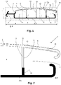
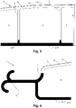
- In order to clarify the invention, a preferred embodiment of a profile according to the invention is described below, with reference to the following figures, in which
-
figure 1 represents a cross-section of a profile according to the invention, and -
figures 2 ,3 and 4 represent the parts of the profile offigure 1 indicated by F2, F3 and F4 on a larger scale. - The
profile 1 shown in the figures has a total width B of 73 mm and a total height H of 14 mm. The relative dimensions of the various parts of theprofile 1 are correctly shown in the figures. Theprofile 1 extends in a profile direction P. - On a side, the
profile 1 is provided with acoupling member 2 with a double hook shape. On the opposite side, theprofile 1 is provided with agroove 3 which can receive such acoupling member 2, such thatsuch profiles 1 can be laterally mutually coupled to form a swimming pool cover. - The
profile 1 comprises abottom wall 4 and a firsttop wall 5 and a secondtop wall 6. The firsttop wall 5 is connected to thebottom wall 4 by means of four connectingwalls 7 which define three closedhollow channels 8 between thebottom wall 4 and the firsttop wall 5. One of the connectingwalls 7, in this example the rightmost connecting wall, also forms theside wall 9 of thegroove 3. The secondtop wall 6 is located above thegroove 3 and is the top wall of thisgroove 3. - The first
top wall 5 and the secondtop wall 6 together form a slightly curved common top wall without kink or angle at the junction between the firsttop wall 5 and the secondtop wall 6. - The
bottom wall 4 extends in this example under both thehollow channels 8 and under thegroove 3. - The
profile 1 comprises four different plastic compositions, as will be explained below, and in this example, but not necessarily, is made of polycarbonate, and is made by means of coextrusion of the four plastic compositions. - The second
top wall 6 consists of three layers of plastic and the firsttop wall 5 consists of two layers of plastic. - The bottom layer of the second
top wall 6, hereinafter referred to as thefirst layer 10 of plastic, is made of a first plastic composition. Thisfirst layer 10 of plastic is opaque, that is to say, it does not transmit light, and has a first colour. The first colour is a medium gray RAL-colour 7004. In the HSV-colour space this corresponds to a first H-value of 0°, a first S-value of 0 and a first V-value of 61%. - The
bottom wall 4 consists of one layer of plastic, hereinafter referred to as thesecond layer 11 of plastic, which is made of a second plastic composition. Thissecond layer 11 of plastic is opaque and has a second colour, which in this example is black, and hence in the HSV-colour space has a second H-value of 0°, a second S-value of 0 and a second V-value of 0. - The bottom layer of the first
top wall 5, hereinafter referred to as thethird layer 12 of plastic, is made of a third plastic composition, and continues into the secondtop wall 6, saidthird layer 12 of plastic forming the intermediate layer of the secondtop wall 6. Thisthird layer 12 of plastic is transparent. - The top layer of the first
top wall 5, hereinafter referred to as thefourth layer 13 of plastic, is made of a fourth plastic composition, and continues into the secondtop wall 6, saidfourth layer 13 of plastic also forming the top layer of the secondtop wall 6. Thisfourth layer 13 of plastic is substantially transparent with a gray metallic lustre and contains an additive that blocks UV light. - The
coupling member 2, just like thebottom wall 4, is made of the second plastic composition. - The upper part of the
side wall 9 of thegroove 3 consists of two layers, more specifically a layer of plastic which is located on the side of thehollow channels 8 and which is made of the third plastic composition and which adjoins thethird layer 12 of plastic, and a layer, hereinafter referred to as thefifth layer 14 of plastic, located on the side of thegroove 3. Thisfifth layer 14 is made of the first plastic composition and is therefore opaque. Thefifth layer 14 of plastic adjoins thefirst layer 10 of plastic such that together they form a continuous layer made of the first plastic composition. - The
first layer 10 of plastic and thefifth layer 14 of plastic have a thickness of approximately 0.2 mm. Thefourth layer 13 of plastic has a thickness of approximately 0.15 mm. The total wall thickness of the firsttop wall 5, the secondtop wall 6 and thebottom wall 4 is approximately 0.9 mm. - The bottom part of the
side wall 9 of thegroove 3 consists of one layer of plastic, hereinafter referred to as thesixth layer 15 of plastic, which is made of the second plastic composition and is therefore opaque. Thesixth layer 15 of plastic adjoins without interruption thesecond layer 11 of plastic. - The
fifth plastic layer 14 of plastic and thesixth layer 15 of plastic adjoin each other without interruption, such that theentire side wall 9 of thegroove 3 is opaque, as is the secondtop wall 6 and the bottom wall of thegroove 3. - As can be seen in the figures, the bottom part of the connecting
walls 7 is made of the second plastic composition and the top part of the connectingwalls 7 is made of the third plastic composition. Preferably, said top part is at least as high as said bottom part, such that the black colour of the bottom part of the connectingwalls 7 cannot, or only to a very limited extent, be seen from above. - The four plastic compositions are the following:
The first plastic composition consists of opaque polycarbonate with added colorants to obtain RAL-colour 7004. - The second plastic composition consists of polycarbonate with added 0.5% carbon black.
- The third plastic composition consists of transparent polycarbonate.
- The fourth plastic composition consists of transparent polycarbonate with 3% gray metallic masterbatch and an additive that blocks UV light. This masterbatch has RAL-colour 9007. In the HSV-colour space, this corresponds to an H-value of 60°, an S-value of 4% and a V-value of 53%.
- The average light transmittance of the first
top wall 5 is 42% in the interval 380nm to 750nm. This was measured using a Shimadzu UV-1800 spectrofotometer according to standard NBN EN ISO 13468-2 : 2006. - Due to the large light transmittance of the first
top wall 5 and the black colour of thebottom wall 4, when used in a swimming pool cover of mutually coupled profiles, a large part of the light falling onto the profiles is absorbed by thebottom wall 4. This energy is then delivered to the water resulting into heating up. - At the same time, no sunlight can get into the
groove 3 because the secondtop wall 6 andside wall 9 of thegroove 3 are opaque. This prevents algae growth in stagnant water in thegroove 3, and any contamination is hidden from view. - Because the
first layer 10 is designed in a lighter colour than thesecond layer 11, i.e. thebottom wall 4, it is largely or completely avoided that a zebra-like pattern of dark lines and light lines is formed in the swimming pool cover. - It can easily be determined experimentally which colour the
first layer 10 of plastic should have in order, at given colours of thesecond layer 11 of plastic and/or thethird layer 12 of plastic and/or thefourth layer 13 of plastic, to have the lowest possible zebra effect. As a guideline, it is recommended that the first H-value may only deviate slightly from the second H-value, that the two S-values are preferably limited, and that the first V-value is higher than the second V-value. - In case the
third layer 12 of plastic or thefourth layer 13 of plastic are coloured, it is additionally recommended that the H-value, V-value and S-value of the colour of thethird layer 12 of plastic or thefourth layer 13 of plastic are preferably only slightly deviating from the first H-value, the first S-value and the first V-value. - The presence of the
third layer 12 of plastic and thefourth layer 13 of plastic, each with its own optical properties, which form the two top layers of both the firsttop wall 5 and the secondtop wall 6, further contribute to masking this zebra-like pattern. - A second embodiment of a profile according to the invention differs from the profile described above in that the fourth plastic composition has the transparent RAL-colour 110 70 70-P-T, also to be referred to as the third colour, and in that the first plastic composition has a first colour which is the non-transparent RAL-colour 110 50 55-P.
- The third colour RAL 110 70 70-P-T corresponds in the HSV-colour space to a third H-value of 66°, a third S-value of 100% and a third V-value of 69%.
- The first colour RAL 110 50 55-P corresponds in the HSV-colour space to a first H-value of 65°, a third S-value of 100% and a third V-value of 49%.
- The light transmittance of the first
top wall 5 of the alternative profile is 52%, measured in the aforementioned way. - For the sake of completeness it is noted that, although in the above examples, the
third layer 12 and thefourth layer 13 of plastic are arranged in the secondtop wall 6, it is also possible that the top wall of the profile is located at some distance from the top wall of the groove, as is the case, for example, in the profile of figure 5 ofAU-A-21669/95 figure 1 ofEP2295676B1 , such that, in that case, thethird layer 12 andfourth layer 13 of plastic also can be arranged in a wall above the second top wall, hence in the top wall of the profile above the top wall of the groove.
Claims (15)
- Profile (1) for manufacturing a slat for a rollable swimming pool cover, wherein the profile (1) is made of plastic,wherein the profile (1) comprises one or more internal hollow channels (8),wherein the profile (1) has a first top wall (5) located above the one or more hollow channels (8),wherein the profile (1) has a bottom wall (4) under the one or more hollow channels (8), wherein the first top wall (5) and the bottom wall (4) are interconnected by two or more connecting walls (7),wherein the profile (1) is provided on a first side with a groove (3) for receiving a coupling member (2), the groove (3) having a second top wall (6),characterized in that the second top wall (6) comprises a first opaque layer (10) of plastic made of a first plastic composition, wherein the bottom wall (4) comprises a second opaque layer (11) of plastic made of a second plastic composition, wherein the first plastic composition is different from the second plastic composition.
- Profile (1) according to claim 1, characterized in that the first plastic composition has a first colour and the second plastic composition has a second colour, wherein the first colour and the second colour are different.
- Profile (1) according to any one of the previous claims, characterized in that the first top wall (5) comprises a third layer (12) of plastic made of a third plastic composition, wherein the third plastic composition is different from the first plastic composition and is different from the second plastic composition, wherein the third layer (12) of plastic is also located on top of the first opaque layer (10) in the second top wall (6) or in another wall located above the second top wall (6).
- Profile (1) according to claim 3, characterized in that the first top wall (5) comprises a fourth layer (13) of plastic made of a fourth plastic composition, wherein the fourth plastic composition is different from the first plastic composition and is different from the second plastic composition and is different from the third plastic composition.
- Profile (1) according to claim 4, characterized in that the fourth layer (13) of plastic is also located in the second top wall (6) on top of the first opaque layer (10) or in another wall that is located above the second top wall (6).
- Profile (1) according to any one of claims 3 to 5, characterized in that the first plastic composition has a first colour and the third plastic composition or fourth plastic composition has a third colour, wherein the first colour has a first V-value and a first S-value and a first H-value in the HSV-colour space, wherein the third colour has a third V-value and a third S-value and a third H-value in the HSV-colour space, wherein the difference between the first V-value and the third V-value is at most 40 percentage points, wherein the difference between the first S-value and the third S-value is at most 40 percentage points and wherein the absolute value of ((first H-value - third H-value) modulo 360°) is less than 90°, wherein, in case there is no fourth layer (13) of plastic or the fourth layer (13) of plastic is colourless, the third plastic composition has said third colour and wherein, in other cases, the fourth plastic composition has said third colour.
- Profile (1) according to any one of the previous claims, characterized in that the first opaque layer (10) of plastic forms the bottom layer of the second top wall (6).
- Profile (1) according to any one of the previous claims, characterized in that the groove (3) has a side wall (9) on a side facing the one or more internal hollow channels (8), wherein a portion of this side wall (9), adjacent to the second top wall (6), comprises a fifth opaque layer (14) of plastic made of said first plastic composition.
- Profile (1) according to claim 8, characterized in that the fifth opaque layer (14) of plastic also forms the surface of that part of the side wall (9) facing the groove (3).
- Profile (1) according to claim 8 or 9, characterized in that the bottom part of the side wall (9) of the groove (3) comprises a sixth opaque layer (15) of plastic made of said second plastic composition, wherein the sixth opaque layer (15) of plastic and the fifth opaque layer (14) of plastic in the side wall (9) taken together extend continuously from the bottom wall (4) to the first opaque layer (10) of plastic.
- Profile (1) according to any one of the previous claims, characterized in that Ithe bottom wall consists only of said second opaque layer (11) of plastic.
- Profile (1) according to any one of the previous claims, characterized in that the profile (1) is provided on a second side with a coupling member (2) which is adapted to be inserted into the groove (3) of another identical profile (1) in order to thereby couple two profiles (1) hingedly laterally to each other, the coupling member (2) comprising an opaque layer of plastic, wherein the coupling member (2) is preferably made of the second plastic composition.
- Profile (1) according to any one of the previous claims, characterized in that the first top wall (5) is free of a layer made of said first plastic composition or second plastic composition.
- Profile (1) according to any one of the previous claims, characterized in that the first top wall (5) has at least 30%, and preferably at least 40%, of light transmittance.
- Profile (1) according to any one of the previous claims, characterized in that the first top wall (5) and the bottom wall (4) are interconnected by three or more connecting walls (7).
Applications Claiming Priority (1)
| Application Number | Priority Date | Filing Date | Title |
|---|---|---|---|
| BE20205674A BE1028659B1 (en) | 2020-09-30 | 2020-09-30 | Profile for manufacturing a slat for a roll-up pool cover and roll-up pool cover |
Publications (3)
| Publication Number | Publication Date |
|---|---|
| EP3978709A1 true EP3978709A1 (en) | 2022-04-06 |
| EP3978709B1 EP3978709B1 (en) | 2024-10-30 |
| EP3978709C0 EP3978709C0 (en) | 2024-10-30 |
Family
ID=72840258
Family Applications (1)
| Application Number | Title | Priority Date | Filing Date |
|---|---|---|---|
| EP21196596.7A Active EP3978709B1 (en) | 2020-09-30 | 2021-09-14 | Profile for manufacturing a slat for a rollable swimming pool cover |
Country Status (3)
| Country | Link |
|---|---|
| EP (1) | EP3978709B1 (en) |
| BE (1) | BE1028659B1 (en) |
| PL (1) | PL3978709T3 (en) |
Citations (9)
| Publication number | Priority date | Publication date | Assignee | Title |
|---|---|---|---|---|
| DE3044949A1 (en) | 1980-11-28 | 1982-07-01 | Georg 8000 München Almer | Roller blind covering swimming bath - has bottom part with inclined faces towards sun below transparent top |
| DE4101727A1 (en) | 1991-01-22 | 1992-07-30 | Hans Heinz Helge | Transparent PVC profile for swimming pool cover - has top covering layer of UV resistant transparent plastic |
| FR2719622A1 (en) | 1994-05-09 | 1995-11-10 | Beloou Philippe | Installation of immersed pool cover. |
| AU2166995A (en) | 1994-07-05 | 1996-01-18 | Remco Roller Shutters (Aust) Pty Ltd | Swimming pool cover and slat end cap arrangement |
| DE29604839U1 (en) | 1996-03-15 | 1996-06-13 | Melichar, Roland, 82549 Königsdorf | Profile strip for swimming pool covers and swimming pool cover thus formed |
| DE19646117C1 (en) | 1996-11-08 | 1998-06-10 | Helge Hans Heinz | Solar blind for swimming pool covering |
| FR2761711A1 (en) | 1997-04-03 | 1998-10-09 | Daniel Hebert | Slat for rigid polyvinyl chloride swimming pool cover |
| DE10103204A1 (en) | 2001-01-24 | 2002-07-25 | Hans-Heinz Helge | Profile for separating a space, in particular, for covering a swimming pool comprises a critical region for which a plastic material with a higher Vicat softening temperature is used |
| EP2295676B1 (en) | 2009-08-20 | 2017-11-22 | Hans-Heinz Helge | Solar profile for swimming pool covers |
-
2020
- 2020-09-30 BE BE20205674A patent/BE1028659B1/en active IP Right Grant
-
2021
- 2021-09-14 EP EP21196596.7A patent/EP3978709B1/en active Active
- 2021-09-14 PL PL21196596.7T patent/PL3978709T3/en unknown
Patent Citations (9)
| Publication number | Priority date | Publication date | Assignee | Title |
|---|---|---|---|---|
| DE3044949A1 (en) | 1980-11-28 | 1982-07-01 | Georg 8000 München Almer | Roller blind covering swimming bath - has bottom part with inclined faces towards sun below transparent top |
| DE4101727A1 (en) | 1991-01-22 | 1992-07-30 | Hans Heinz Helge | Transparent PVC profile for swimming pool cover - has top covering layer of UV resistant transparent plastic |
| FR2719622A1 (en) | 1994-05-09 | 1995-11-10 | Beloou Philippe | Installation of immersed pool cover. |
| AU2166995A (en) | 1994-07-05 | 1996-01-18 | Remco Roller Shutters (Aust) Pty Ltd | Swimming pool cover and slat end cap arrangement |
| DE29604839U1 (en) | 1996-03-15 | 1996-06-13 | Melichar, Roland, 82549 Königsdorf | Profile strip for swimming pool covers and swimming pool cover thus formed |
| DE19646117C1 (en) | 1996-11-08 | 1998-06-10 | Helge Hans Heinz | Solar blind for swimming pool covering |
| FR2761711A1 (en) | 1997-04-03 | 1998-10-09 | Daniel Hebert | Slat for rigid polyvinyl chloride swimming pool cover |
| DE10103204A1 (en) | 2001-01-24 | 2002-07-25 | Hans-Heinz Helge | Profile for separating a space, in particular, for covering a swimming pool comprises a critical region for which a plastic material with a higher Vicat softening temperature is used |
| EP2295676B1 (en) | 2009-08-20 | 2017-11-22 | Hans-Heinz Helge | Solar profile for swimming pool covers |
Also Published As
| Publication number | Publication date |
|---|---|
| EP3978709B1 (en) | 2024-10-30 |
| BE1028659A1 (en) | 2022-04-25 |
| BE1028659B1 (en) | 2022-05-02 |
| EP3978709C0 (en) | 2024-10-30 |
| PL3978709T3 (en) | 2025-02-17 |
Similar Documents
| Publication | Publication Date | Title |
|---|---|---|
| US20130264948A1 (en) | Control system for active window glass managing the colour of the light in a building | |
| EP2534329B1 (en) | Z-shaped venetian blind slats for daylight deflection | |
| EP3978709B1 (en) | Profile for manufacturing a slat for a rollable swimming pool cover | |
| US10287818B2 (en) | Shade | |
| US20150368965A1 (en) | Transparent roller shutter | |
| EP3992399A1 (en) | Profile for manufacturing a slat for a swimming pool cover and use of a plastic composition in a swimming pool cover | |
| US20100139874A1 (en) | Perforated louver with design pattern layer and an assembly for such louvers | |
| CA3084523C (en) | Light-redirecting optical daylighting system | |
| US20100263806A1 (en) | Venetian blind system | |
| JP5167017B2 (en) | Temperature control floor sheet | |
| CN216305273U (en) | Connecting structure of adhesive tape and pressing strip in concealed skirting line | |
| KR102142575B1 (en) | Wood Plastic Composition having excellent Tensile Strength and Flame Retardant | |
| EP3006513A1 (en) | Heat-reflective composition | |
| KR20050000577A (en) | adiabatic louver | |
| KR100900194B1 (en) | Infrared cut sheet | |
| EP1903854A1 (en) | Greenhouse panels | |
| EP2325413B1 (en) | A multilayer structure frontally closing a transparent surface in a building for natural ventilation and lighting | |
| PT2295676T (en) | Solar profile for swimming pool covers | |
| Fontoynont et al. | SynthLight handbook | |
| KR200331495Y1 (en) | adiabatic louver | |
| KR101857118B1 (en) | Translucent panel for building | |
| KR200412562Y1 (en) | Main door | |
| CN109236127A (en) | A kind of garage security door | |
| US20050175804A1 (en) | Near infrared absorbing acrylic construction blocks | |
| EP3315469A1 (en) | Ceramic lining sheet for external use |
Legal Events
| Date | Code | Title | Description |
|---|---|---|---|
| PUAI | Public reference made under article 153(3) epc to a published international application that has entered the european phase |
Free format text: ORIGINAL CODE: 0009012 |
|
| STAA | Information on the status of an ep patent application or granted ep patent |
Free format text: STATUS: THE APPLICATION HAS BEEN PUBLISHED |
|
| AK | Designated contracting states |
Kind code of ref document: A1 Designated state(s): AL AT BE BG CH CY CZ DE DK EE ES FI FR GB GR HR HU IE IS IT LI LT LU LV MC MK MT NL NO PL PT RO RS SE SI SK SM TR |
|
| STAA | Information on the status of an ep patent application or granted ep patent |
Free format text: STATUS: REQUEST FOR EXAMINATION WAS MADE |
|
| 17P | Request for examination filed |
Effective date: 20220701 |
|
| RBV | Designated contracting states (corrected) |
Designated state(s): AL AT BE BG CH CY CZ DE DK EE ES FI FR GB GR HR HU IE IS IT LI LT LU LV MC MK MT NL NO PL PT RO RS SE SI SK SM TR |
|
| GRAP | Despatch of communication of intention to grant a patent |
Free format text: ORIGINAL CODE: EPIDOSNIGR1 |
|
| STAA | Information on the status of an ep patent application or granted ep patent |
Free format text: STATUS: GRANT OF PATENT IS INTENDED |
|
| INTG | Intention to grant announced |
Effective date: 20240725 |
|
| GRAS | Grant fee paid |
Free format text: ORIGINAL CODE: EPIDOSNIGR3 |
|
| GRAA | (expected) grant |
Free format text: ORIGINAL CODE: 0009210 |
|
| STAA | Information on the status of an ep patent application or granted ep patent |
Free format text: STATUS: THE PATENT HAS BEEN GRANTED |
|
| AK | Designated contracting states |
Kind code of ref document: B1 Designated state(s): AL AT BE BG CH CY CZ DE DK EE ES FI FR GB GR HR HU IE IS IT LI LT LU LV MC MK MT NL NO PL PT RO RS SE SI SK SM TR |
|
| REG | Reference to a national code |
Ref country code: GB Ref legal event code: FG4D |
|
| REG | Reference to a national code |
Ref country code: CH Ref legal event code: EP |
|
| REG | Reference to a national code |
Ref country code: IE Ref legal event code: FG4D |
|
| REG | Reference to a national code |
Ref country code: DE Ref legal event code: R096 Ref document number: 602021020926 Country of ref document: DE |
|
| U01 | Request for unitary effect filed |
Effective date: 20241107 |
|
| U07 | Unitary effect registered |
Designated state(s): AT BE BG DE DK EE FI FR IT LT LU LV MT NL PT RO SE SI Effective date: 20241115 |
|
| PG25 | Lapsed in a contracting state [announced via postgrant information from national office to epo] |
Ref country code: IS Free format text: LAPSE BECAUSE OF FAILURE TO SUBMIT A TRANSLATION OF THE DESCRIPTION OR TO PAY THE FEE WITHIN THE PRESCRIBED TIME-LIMIT Effective date: 20250228 Ref country code: HR Free format text: LAPSE BECAUSE OF FAILURE TO SUBMIT A TRANSLATION OF THE DESCRIPTION OR TO PAY THE FEE WITHIN THE PRESCRIBED TIME-LIMIT Effective date: 20241030 |
|
| PG25 | Lapsed in a contracting state [announced via postgrant information from national office to epo] |
Ref country code: ES Free format text: LAPSE BECAUSE OF FAILURE TO SUBMIT A TRANSLATION OF THE DESCRIPTION OR TO PAY THE FEE WITHIN THE PRESCRIBED TIME-LIMIT Effective date: 20241030 |
|
| PG25 | Lapsed in a contracting state [announced via postgrant information from national office to epo] |
Ref country code: NO Free format text: LAPSE BECAUSE OF FAILURE TO SUBMIT A TRANSLATION OF THE DESCRIPTION OR TO PAY THE FEE WITHIN THE PRESCRIBED TIME-LIMIT Effective date: 20250130 |
|
| PG25 | Lapsed in a contracting state [announced via postgrant information from national office to epo] |
Ref country code: GR Free format text: LAPSE BECAUSE OF FAILURE TO SUBMIT A TRANSLATION OF THE DESCRIPTION OR TO PAY THE FEE WITHIN THE PRESCRIBED TIME-LIMIT Effective date: 20250131 |
|
| PG25 | Lapsed in a contracting state [announced via postgrant information from national office to epo] |
Ref country code: RS Free format text: LAPSE BECAUSE OF FAILURE TO SUBMIT A TRANSLATION OF THE DESCRIPTION OR TO PAY THE FEE WITHIN THE PRESCRIBED TIME-LIMIT Effective date: 20250130 |
|
| PG25 | Lapsed in a contracting state [announced via postgrant information from national office to epo] |
Ref country code: SM Free format text: LAPSE BECAUSE OF FAILURE TO SUBMIT A TRANSLATION OF THE DESCRIPTION OR TO PAY THE FEE WITHIN THE PRESCRIBED TIME-LIMIT Effective date: 20241030 |
|
| PG25 | Lapsed in a contracting state [announced via postgrant information from national office to epo] |
Ref country code: SK Free format text: LAPSE BECAUSE OF FAILURE TO SUBMIT A TRANSLATION OF THE DESCRIPTION OR TO PAY THE FEE WITHIN THE PRESCRIBED TIME-LIMIT Effective date: 20241030 |
|
| PLBE | No opposition filed within time limit |
Free format text: ORIGINAL CODE: 0009261 |
|
| STAA | Information on the status of an ep patent application or granted ep patent |
Free format text: STATUS: NO OPPOSITION FILED WITHIN TIME LIMIT |
|
| REG | Reference to a national code |
Ref country code: CH Ref legal event code: U11 Free format text: ST27 STATUS EVENT CODE: U-0-0-U10-U11 (AS PROVIDED BY THE NATIONAL OFFICE) Effective date: 20251001 |
|
| 26N | No opposition filed |
Effective date: 20250731 |
|
| PGFP | Annual fee paid to national office [announced via postgrant information from national office to epo] |
Ref country code: TR Payment date: 20250721 Year of fee payment: 5 Ref country code: PL Payment date: 20250716 Year of fee payment: 5 |
|
| PGFP | Annual fee paid to national office [announced via postgrant information from national office to epo] |
Ref country code: GB Payment date: 20250714 Year of fee payment: 5 |
|
| PGFP | Annual fee paid to national office [announced via postgrant information from national office to epo] |
Ref country code: CZ Payment date: 20250902 Year of fee payment: 5 |
|
| U20 | Renewal fee for the european patent with unitary effect paid |
Year of fee payment: 5 Effective date: 20250923 |
|
| PGFP | Annual fee paid to national office [announced via postgrant information from national office to epo] |
Ref country code: CH Payment date: 20251001 Year of fee payment: 5 |