EP3978348A1 - Dispositif d'amarrage d'un bateau - Google Patents
Dispositif d'amarrage d'un bateau Download PDFInfo
- Publication number
- EP3978348A1 EP3978348A1 EP21200355.2A EP21200355A EP3978348A1 EP 3978348 A1 EP3978348 A1 EP 3978348A1 EP 21200355 A EP21200355 A EP 21200355A EP 3978348 A1 EP3978348 A1 EP 3978348A1
- Authority
- EP
- European Patent Office
- Prior art keywords
- buoy
- mooring
- boat
- water
- state
- Prior art date
- Legal status (The legal status is an assumption and is not a legal conclusion. Google has not performed a legal analysis and makes no representation as to the accuracy of the status listed.)
- Withdrawn
Links
- XLYOFNOQVPJJNP-UHFFFAOYSA-N water Substances O XLYOFNOQVPJJNP-UHFFFAOYSA-N 0.000 claims abstract description 78
- 238000007667 floating Methods 0.000 claims abstract description 32
- 230000000295 complement effect Effects 0.000 claims abstract description 30
- 238000004891 communication Methods 0.000 claims abstract description 21
- 238000001514 detection method Methods 0.000 claims description 24
- 230000001133 acceleration Effects 0.000 claims description 4
- 230000003993 interaction Effects 0.000 claims 1
- 238000005096 rolling process Methods 0.000 claims 1
- 238000005259 measurement Methods 0.000 description 10
- 238000005188 flotation Methods 0.000 description 6
- 238000000034 method Methods 0.000 description 4
- 230000000694 effects Effects 0.000 description 3
- 230000000284 resting effect Effects 0.000 description 3
- BASFCYQUMIYNBI-UHFFFAOYSA-N platinum Chemical compound [Pt] BASFCYQUMIYNBI-UHFFFAOYSA-N 0.000 description 2
- 230000003213 activating effect Effects 0.000 description 1
- 230000005540 biological transmission Effects 0.000 description 1
- QVFWZNCVPCJQOP-UHFFFAOYSA-N chloralodol Chemical compound CC(O)(C)CC(C)OC(O)C(Cl)(Cl)Cl QVFWZNCVPCJQOP-UHFFFAOYSA-N 0.000 description 1
- 238000010292 electrical insulation Methods 0.000 description 1
- 238000005516 engineering process Methods 0.000 description 1
- 239000011810 insulating material Substances 0.000 description 1
- 229910052697 platinum Inorganic materials 0.000 description 1
- 229910001220 stainless steel Inorganic materials 0.000 description 1
- 239000010935 stainless steel Substances 0.000 description 1
- 239000000725 suspension Substances 0.000 description 1
- 238000013519 translation Methods 0.000 description 1
- 230000014616 translation Effects 0.000 description 1
- 238000011179 visual inspection Methods 0.000 description 1
- 239000011800 void material Substances 0.000 description 1
Images



Classifications
-
- B—PERFORMING OPERATIONS; TRANSPORTING
- B63—SHIPS OR OTHER WATERBORNE VESSELS; RELATED EQUIPMENT
- B63B—SHIPS OR OTHER WATERBORNE VESSELS; EQUIPMENT FOR SHIPPING
- B63B22/00—Buoys
- B63B22/02—Buoys specially adapted for mooring a vessel
-
- B—PERFORMING OPERATIONS; TRANSPORTING
- B63—SHIPS OR OTHER WATERBORNE VESSELS; RELATED EQUIPMENT
- B63B—SHIPS OR OTHER WATERBORNE VESSELS; EQUIPMENT FOR SHIPPING
- B63B22/00—Buoys
- B63B22/22—Inflatable buoys with gas generating means
-
- B—PERFORMING OPERATIONS; TRANSPORTING
- B63—SHIPS OR OTHER WATERBORNE VESSELS; RELATED EQUIPMENT
- B63B—SHIPS OR OTHER WATERBORNE VESSELS; EQUIPMENT FOR SHIPPING
- B63B22/00—Buoys
- B63B22/18—Buoys having means to control attitude or position, e.g. reaction surfaces or tether
Definitions
- the invention belongs to the field of mooring devices for boats, in particular pleasure boats.
- the invention relates more particularly to a device for mooring a boat, comprising a mooring point such as a mooring buoy, a pontoon, a quay or even a post, a mooring line fixed to the mooring point by a main segment and a buoy, attached to the mooring line by a complementary segment and assuming a floating state or a state out of the water when respectively, a boat is not or is moored at the mooring point, the buoy being ballasted by the mooring line in the state of flotation, while in the state out of water, it is linked to a boat moored by the complementary segment, the main segment being alone intended to be fixed to the boat to support a force of traction exerted by the boat.
- a mooring point such as a mooring buoy, a pontoon, a quay or even a post
- a mooring line fixed to the mooring point by a main segment and a buoy attached to the moor
- the figures 1 to 4 illustrate a mooring device of this type known per se.
- the main segment of the mooring is counted between an attachment loop at the mooring point, here a mooring buoy, and an attachment loop at a fixed point on a boat.
- the complementary segment makes it possible, for example, to suspend the buoy in a vacuum or to place it on the boat.
- WO 2016/015089 discloses a mooring device in which a mooring buoy forms a mooring point for a boat.
- a tether is attached to the mooring point by a first segment.
- a second segment is intended to be fixed to the boat.
- the two segments of the mooring line are connected by a buoy to which they are fixed.
- the buoy changes from a state of flotation to a state out of water depending on the traction exerted by the boat on the mooring line.
- the buoy comprises means for detecting the state out of water and communication means for sending to a management center a signal establishing a relationship between the state out of water detected and the mooring of a boat at the mooring point.
- the detection of the state out of water according to this mooring device is random, because it depends on the movement of the boat relative to the mooring point.
- the buoy In calm seas, the buoy can remain in the floating state for a long period of time, during which the detection means do not detect any change in state. During this time interval, it is not possible to check a previously established relationship between the detected out of water state and the mooring of a boat. An accidental or intentional unmooring may have occurred without being detected, the buoy having remained in the floating state.
- One of the aims of the invention is to increase the reliability of a mooring device.
- the subject of the invention is a device for mooring a boat, comprising a mooring point such as a mooring buoy, a pontoon, a quay or even a post, a mooring line, fixed to the point of mooring by a main segment and a buoy, attached to the mooring line by a complementary segment and assuming a floating state or an out of water state when respectively a boat is not or is moored at the mooring point, the buoy being weighted by the mooring in the state of flotation while in the state out of water, it is linked to a boat moored by the complementary segment, the main segment being alone intended to be fixed to the boat to support a force of traction exerted by the boat on the mooring line, characterized in that the buoy comprises means for detecting the floating state and the state out of the water and communication means for sending in real time to a management center , signals establishing a one-to-one relationship between the floating or hor s
- the detection means are arranged in the buoy to take advantage of the fact that the state out of the water is determined by the single complementary segment of the mooring line. It therefore forms a state independent of the movements of the boat with respect to the mooring point.
- the different roles played by the main segment and by the complementary segment of the mooring line allow the detection means to detect any change in the state of the buoy over time, whether floating or out of the water.
- the means of communication can thus send signals in real time which establish a unique relationship between the state of flotation and the unsecured state on the one hand and the state out of the water and the securement of a boat on the other. go.
- a part of the buoy by which it is attached to the complementary segment of the mooring includes, below the waterline, a water chamber filling with water in the floating state and a water presence detector interacting with said chamber.
- the buoy In the out-of-water state, the buoy is connected to the boat by the complementary segment, in a position suspended in a vacuum or resting on the boat, allowing the water contained in the chamber to be evacuated.
- the presence or absence of water detected by the detection means allows the communication means to send in real time, a water presence signal indicating that no boat is moored at the mooring point. or an out of water signal, indicating that a boat is moored.
- the water presence detector preferably implements a measurement of the pressure-static, ultrasonic, propagation of electromagnetic waves or electrical resistance type. It is electrically isolated from the water chamber.
- the detection means comprise an inclinometer, capable of detecting an angle variation with respect to an angle specific to the buoy, defined as the opening angle alpha of a bearing cone of the buoy on a horizontal plane, having a vertex determined by means of attachment of the buoy to the complementary mooring segment.
- the angle specific to the buoy or a value greater than this angle, is associated with the out of water state. In the floating state, the buoy pivots on itself by an angular value equal to the opposite of its own angle, the means of attachment to the complementary mooring segment being in alignment with the center of mass of buoy and Archimedes thrust.
- the buoy When the inclinometer is located relative to the vertical of the place, the buoy presents at time t an angle beta which oscillates around zero in the floating state and which oscillates around the angle alpha or a value greater than alpha, in the position out of the water, depending on whether it is placed on a support on the boat or suspended in a vacuum.
- the alpha angle or the beta angle detected by the inclinometer allows the means of communication to send in real time, an unambiguous signal indicating that no boat is moored at the mooring point - beta angle - or that a boat is moored - angle alpha or greater than alpha.
- the invention advantageously provides two methods making it possible to significantly reduce their influence.
- One of these methods consists in defining a confidence interval of about ten degrees when measuring the angle variation with respect to the angle specific to the buoy.
- the inclinometer is able to process the ratios of the accelerations between two of the three directions in space, for example x / z Where there / z , to reduce the effect of linear accelerations, such as variations in height or horizontal translations, while angular variations, on which the waves have little influence, are eliminated by carrying out a sliding average of the angles measured over a pre-established duration, for example during the five periods of a wave, or by counting a fixed number of complete waves, measured between particular points, such as the maximum.
- the invention provides for simultaneously activating the detection principles explained previously, by the presence of water and by variation of the proper angle of the buoy.
- connected objects IoT Internet of Things
- An SMS or equivalent message can also be sent to the owner or the user of the boat, each time the buoy status changes, floating or out of the water, informing him in real time respectively of the non-mooring or the mooring the boat and alerting it in the event of accidental or intentional unhooking, theft or unauthorized mooring at the mooring point reserved for it.
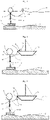
- the fig. 1 shows a mooring device known per se, comprising a mooring buoy, a mooring line and a buoy attached to the mooring line in a floating state.
- the fig. 2 shows the mooring device illustrated by the figure 1 , the buoy attached to the mooring line being out of the water and placed on a boat moored to the mooring buoy.
- the fig. 3 shows the mooring device illustrated by the figure 1 , the buoy attached to the mooring line being out of the water and suspended from a boat moored to the mooring buoy.
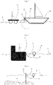
- the fig. 4 shows the mooring device illustrated by the figure 1 , in which the mooring buoy is replaced by a pontoon.
- the fig. 5 shows the mooring device illustrated by the figure 1 , in which the mooring buoy is replaced by a quay.
- the fig. 6 shows the mooring device illustrated by the figure 1 , in which the mooring buoy is replaced by a pole.
- the fig. 7 shows a first embodiment of the invention, in which the buoy attached to the mooring comprises a water chamber and water presence detectors carrying out an ultrasonic type measurement.
- the fig. 8 shows different embodiments of the means for detecting the presence of water, of the buoy illustrated by the figure 7 .
- the fig. 9 shows an alternative embodiment of the buoy illustrated by the figure 7 , in which the detection means carry out an electrical resistance measurement.
- the fig. 10 shows the means of detection illustrated by the figure 9 with an enlargement.
- the fig. 11 shows in front view, a second embodiment of the invention, in which the buoy attached to the mooring comprises an inclinometer.
- the fig. 12 shows the buoy illustrated by the figure 11 , in profile view.
- the fig. 13 shows the buoy illustrated by the figures 11 and 12 , resting on a horizontal plane.
- the fig. 14 shows the buoy illustrated by the figures 11 and 12 , in a floating state.
- the fig. 15 shows the buoy illustrated by the figures 11 and 12 , in a state out of water, suspended in a vacuum.
- the fig. 16 shows a buoy adapted to miniature means of detection and communication.
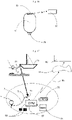
- the fig. 17 shows a buoy attached to the mooring line according to the first or the second embodiment of the invention, comprising means of communication sending signals autonomously to a management center.
- the fig. 18 shows a buoy attached to the mooring line according to the first or the second embodiment of the invention, comprising communication means sending signals to a management center via a mooring buoy.
- a mooring device known per se is illustrated by the figures 1 to 3 . It includes a mooring point, here a mooring buoy 1 connected by a chain 5 to a dead body 3 resting on the seabed 2.
- a mooring line is attached to the mooring buoy 1 by a main mooring segment 7.
- a second buoy 11 is attached to the mooring line by a complementary mooring line segment 9, via an attachment means, here a swivel 6.
- the second buoy 11 assumes a floating state at the surface of the water 4, represented by the figure 1 or a state out of water, represented by the picture 2 or 3 , when respectively, a boat 13 is not or is moored to the mooring buoy 1.
- the second buoy 11 is weighted by the two segments 7, 9 of the mooring line in the floating state and serves to facilitate taking of the mooring line during mooring.
- the second buoy 11 is linked to the moored boat 13 by the complementary segment 9, independently of the main segment 7, which alone is intended to be fixed to the boat 13, here by means of a cleat 15, to support a tractive effort exerted by the boat 13 according to its movements in the water around the mooring buoy 1.
- main mooring segment 7 has various names depending on the customs of the place. Thus, it is called hawser (or hawser), a term which encompasses any rope ensuring a connection between a boat and a mooring point such as a pontoon, a quay, or even a post sunk into the seabed. It is also called whip when it comes to the connection between a boat and a mooring buoy.
- the second buoy 11 which is attached to the mooring line by the complementary segment 9 is called secondary buoy with respect to the mooring buoy, which is called main buoy.
- the figure 2 shows the mooring device illustrated by the figure 1 , the buoy 11 attached to the complementary mooring segment 9 being out of the water and placed on the boat 13 moored to the mooring buoy 1.
- the picture 3 shows the mooring device illustrated by the figure 1 , the buoy 11 attached to the complementary mooring segment 9 being out of the water and suspended in a vacuum from the boat 13 moored to the mooring buoy 1.
- the second buoy 11 is thus made clearly visible for visual inspection. This state in suspension can be imposed through an administrative regulation of a mooring park.
- the figure 4 shows the mooring device illustrated by the figure 1 , in which the mooring buoy 11 is replaced by a pontoon 17 to which the mooring line is fixed by its main segment 7.
- the boat 13 is moored to the pontoon 17 by the main mooring segment 7 caught in the cleat 15.
- the second buoy 11 is suspended in the void, hanging from the boat 13 by the complementary mooring segment 9.
- the figure 5 shows the mooring device illustrated by the figure 1 , in which the mooring buoy 1 is replaced by a quay 19.
- the figure 6 shows the mooring device illustrated by the figure 1 , in which the mooring buoy 1 is replaced by a pole 21. In these last two figures, the second buoy 11 is in the floating state.
- the figure 7 shows a first embodiment of the invention, in which the buoy 11, attached to the mooring line by the complementary segment 9, comprises a water chamber 23 and a water presence detector 25 carrying out an ultrasonic type measurement .
- the water chamber 23 is formed in a part 27, also called an unbalance, by which the buoy 11 is attached to the complementary segment of the mooring line 9.
- the unbalance 27 thus comprises an opening 29 serving as a socket for a fixing means, for example the swivel 6 indicated above.
- the water chamber 23 is arranged below the waterline 31 of the buoy 11 to fill with water when the buoy 11 is in the floating state. Channels 33 opening out through orifices 35 are thus provided to place the water chamber 23 in communication with the surrounding water.
- the water presence detector 25 is integrated into the unbalance 27 which thus serves as its protection and electrical insulation.
- the figure 8 shows different embodiments of the means for detecting the presence of water.
- a detector carrying out a measurement by wave propagation in the infrared comprises an emitting diode 37 and a receiving diode 39. It should be recalled that water has a strong effect on infrared propagation. and that thus, it is easy to detect its presence or absence.
- Another detector performing an electrical resistance measurement comprises two platinum electrodes 41, making it possible to detect the presence or absence of water between the two electrodes.
- a first electrode comprises, figure 10 , a stainless steel washer 43, housed in a casing made of insulating material 45.
- a water chamber is formed by a gap 46 between the casing and the wall 61 of the buoy 11.
- the first electrode 43 is in communication with the chamber water through openings 47.
- a second electrode is formed by a ring 49 allowing the fixing of the complementary segment 9 of the mooring line.
- An electronic box 51 is placed in opposition to the fixing ring 49 with respect to the waterline.
- the electrical connection between the electronic box 51 and the first electrode 43 is provided by an electrical wire 55.
- the electrical connection with the second electrode 49 is provided by a pin 53 arranged along a diameter of the buoy 11.
- An antenna 57 emitting a signal detection 59 is also arranged above the waterline 31, to ensure a good emission in the buoy 11 floating state.
- the figures 11 and 12 illustrate a second embodiment of the invention, in which the buoy 11, attached to the complementary segment 9 of the mooring line, comprises an inclinometer 60.
- An inflation valve 63 is fixed on a wall 61 of the buoy 11.
- Means for communication with a management center comprise an electronic circuit 65, powered by batteries 67 and an antenna 69, arranged above the waterline, so as to allow good transmission of the detection signal in the waterline state of the buoy 11.
- the inclinometer 60 performs an angle measurement using an accelerometer with 3 perpendicular axes.
- a ring 71 is arranged below the waterline to attach the buoy 11 to the complementary segment 9 of the mooring line.
- the figures 13 to 15 illustrate different angular positions of the buoy 11.
- the figure 13 illustrates more particularly the angle alpha, specific to the buoy 11 and defined as the angle of opening of a support cone of the buoy 11 on a horizontal plane 73, having a vertex determined by the ring 71 serving as 'attaches to the complementary segment 9.
- the buoy here is spherical or ovoid in shape and the angle alpha depends on the diameter of the buoy 11 as well as the radial extension of the ring 71.
- the angle alpha specific to the buoy, or a value greater than this angle, is associated with the out of water state.
- the buoy 11 pivots on itself by an angular value equal to the opposite of its proper angle, the ring 71 being in alignment with the center of mass of the buoy and the thrust of Archimedes.
- the buoy present at time t, an angle beta which oscillates around zero in the floating state, figure 14 and which oscillates around the angle alpha or a value greater than alpha, in the out-of-water position, depending on whether it is placed on a horizontal support of the boat or suspended in a vacuum, figure 15 .
- the alpha angle or the beta angle detected by the inclinometer allows the means of communication to send in real time, an unambiguous signal indicating that no boat is moored at the mooring point - beta angle - or that a boat is moored - angle alpha or greater than alpha.
- the buoy 11 is in the floating state by checking that the angle beta detected with respect to the vertical is less than the angle alpha specific to the buoy.
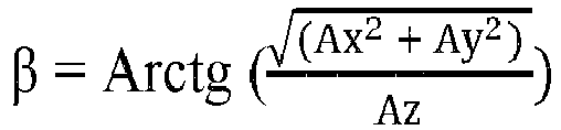
- the measurement of the inclination of the buoy 11 is obtained using the three-axis accelerometer attached to the buoy 11.
- the inclinometer measures the three accelerations Ax, Ay, and Az.
- the buoy 11 may comprise detection means of the two types described above.
- the ring 71 is fixed to a part 79 which allows access to the interior of the buoy 11 and which comprises a water chamber 81 and electrodes for measuring the electrical resistance of the chamber or any other means of detection of the presence of water.
- the detection of the presence of water must corroborate the detection of the beta angle.
- the detection of the absence of water must corroborate the detection of the angle alpha or a greater value. A lack of concordance will reveal an anomaly of the device, or even attempts at cheating.
- the figure 16 illustrates a buoy 11 of non-spherical shape, adapted to the miniaturization of means of communication.
- the ring 71 for attachment to the complementary mooring segment 9 and means of communication have been shown, in the form of an IoT module 83.
- This IoT module can be powered by button cells, or even a solar panel. It can be supplemented by a possible transponder 85, fixed near the mooring point or on a boat, the transponder being able to be paired during the first mooring.
- the figure 17 and 18 illustrate two modes of communication between the buoy 11 and a management center 88. Communication can be ensured by one of the Lora or Sigfox type IoT networks, directly between the buoy 11 and the management center 88, or via a transponder 85, placed on the mooring buoy 1 or any other mooring point, or even on a boat 13.
- the detection means are in communication with a microprocessor which emits the signals establishing the unambiguous relationship between the state of flotation and the state out of water detected by the detection means and respectively the non-mooring or the mooring of 'a boat.
- These means of communication can also exchange administrative data such as an identification number, entered manually or through an RFID module, or even messages from the boat through a proximity connection of the WIFI or Bluetooth type and which can contain other information, such as the list of mooring rights and conditions, the position of the boat given by a GPS module, the water or air temperature, the voltage of the power supply elements, etc. .
- the figure 17 more particularly illustrates a buoy 11 comprising a central microprocessor 87, in communication with detection means, here electrodes 89 performing an electrical resistance measurement in the water chamber of the buoy, a WIFI dialogue module 91, an RFID module 93 card reader and an IoT 95 link to an Internet 97 network.
- the figure 18 more particularly illustrates a buoy 11 coupled with a transponder arranged on a mooring buoy 1.
- the buoy 11 comprises a first central microprocessor 99 while the mooring buoy comprises
- the two buoys communicate by a wired or radio proximity link 105.
- An SMS or equivalent message is sent in real time to the owner or user of the boat, each time the buoy 11 changes state detected by the detection means, either floating or out of the water, which allows to highlight an accidental or intentional unhooking of the boat, theft, or even illegal mooring.
Landscapes
- Chemical & Material Sciences (AREA)
- Engineering & Computer Science (AREA)
- Combustion & Propulsion (AREA)
- Mechanical Engineering (AREA)
- Ocean & Marine Engineering (AREA)
- Testing Or Calibration Of Command Recording Devices (AREA)
Abstract
Dispositif d'amarrage d'un bateau, comprenant un point d'amarrage tel une bouée de mouillage (1), une amarre (7, 9), fixée au point d'amarrage (1) par un segment d'amarre principal (7) et une bouée (11), attachée à l'amarre (7, 9) par un segment d'amarre complémentaire (9) et prenant un état de flottaison ou un état hors d'eau lorsque respectivement, un bateau (13) n'est pas ou est amarré au point d'amarrage (1, 17, 19, 21), la bouée étant lestée par l'amarre (7, 9) dans l'état de flottaison tandis que dans l'état hors d'eau, elle est liée à un bateau amarré (13) par le segment complémentaire (9), le segment principal (7) étant seul destiné à être fixé au bateau (13) pour supporter un effort de traction exercé par le bateau sur le point d'amarrage (1).Selon l'invention, la bouée (11) comprend des moyens pour détecter l'état en flottaison et l'état hors d'eau et des moyens de communication (87) pour envoyer en temps réel à une centrale de gestion (88), des signaux (95, 97) établissant une relation univoque entre l'état en flottaison ou hors d'eau détecté et respectivement, le non amarrage ou l'amarrage d'un bateau au point d'amarrage.
Description
- L'invention appartient au domaine des dispositifs d'amarrage des bateaux, notamment des bateaux de plaisance.
- Aujourd'hui, les gestionnaires d'aires de stationnement cherchent à mieux connaître et mieux contrôler l'état de leur parc d'amarrage, à des fins d'optimisation du taux d'occupation et en particulier, de la mise à disposition de points d'amarrage libérés temporairement ou du contrôle d'occupations non autorisées.
- L'invention se rapporte plus particulièrement à un dispositif d'amarrage d'un bateau, comprenant un point d'amarrage tel une bouée de mouillage, un ponton, un quai ou encore un poteau, une amarre fixée au point d'amarrage par un segment principal et une bouée, attachée à l'amarre par un segment complémentaire et prenant un état de flottaison ou un état hors d'eau lorsque respectivement, un bateau n'est pas ou est amarré au point d'amarrage, la bouée étant lestée par l'amarre dans l'état de flottaison, tandis que dans l'état hors d'eau, elle est liée à un bateau amarré par le segment complémentaire, le segment principal étant seul destiné à être fixé au bateau pour supporter un effort de traction exercé par le bateau.
- Les
figures 1 à 4 illustrent un dispositif d'amarrage de ce type connu en soi. Le segment principal de l'amarre est compté entre une boucle de fixation au point d'amarrage, ici une bouée de mouillage, et une boucle de fixation à un point fixe d'un bateau. Lorsque le segment principal relie un bateau au point d'amarrage, le segment complémentaire permet par exemple de suspendre la bouée dans le vide ou de la poser sur le bateau. - Le document
WO 2016/015089 divulgue un dispositif d'amarrage dans lequel une bouée de mouillage forme un point d'amarrage d'un bateau. Une amarre est fixée au point d'amarrage par un premier segment. Un deuxième segment est destiné à être fixé au bateau. Les deux segments de l'amarre sont reliés par une bouée à laquelle ils sont fixés. Lorsque le bateau est à une distance inférieure à la longueur totale de l'amarre, égale à la somme des longueurs des deux segments (la taille propre de la bouée étant négligée) la traction exercée par le bateau est nulle et la bouée est en état de flottaison. Lorsque le bateau est entraîné à une distance qui tend vers la longueur totale de l'amarre, la traction sur chaque segment de l'amarre a pour effet de tirer la bouée hors de l'eau. Celle-ci reprend son état flottant lorsque la traction s'annule à nouveau, en fonction des déplacements du bateau par rapport au point d'amarrage. Ainsi, la bouée passe d'un état de flottaison à un état hors d'eau en fonction de la traction exercée par le bateau sur l'amarre. La bouée comprend des moyens pour détecter l'état hors d'eau et des moyens de communication pour envoyer à une centrale de gestion, un signal établissant une relation entre l'état hors d'eau détecté et l'amarrage d'un bateau au point d'amarrage. - La détection de l'état hors d'eau selon ce dispositif d'amarrage est aléatoire, car elle dépend des déplacements du bateau par rapport au point d'amarrage. Par mer calme, la bouée peut rester dans l'état de flottaison pendant un long intervalle de temps, au cours duquel les moyens de détection ne détectent aucun changement d'état. Pendant cet intervalle de temps, il n'est pas possible de contrôler une relation établie antérieurement entre l'état hors d'eau détecté et l'amarrage d'un bateau. Un désamarrage accidentel ou intentionnel peut être survenu sans avoir été détecté, la bouée étant restée dans l'état de flottaison.
- L'un des buts de l'invention est d'augmenter la fiabilité d'un dispositif d'amarrage.
- A cet effet, l'invention a pour objet un dispositif d'amarrage d'un bateau, comprenant un point d'amarrage tel une bouée de mouillage, un ponton, un quai ou encore un poteau, une amarre, fixée au point d'amarrage par un segment principal et une bouée, attachée à l'amarre par un segment complémentaire et prenant un état de flottaison ou un état hors d'eau lorsque respectivement un bateau n'est pas ou est amarré au point d'amarrage, la bouée étant lestée par l'amarre dans l'état de flottaison tandis que dans l'état hors d'eau, elle est liée à un bateau amarré par le segment complémentaire, le segment principal étant seul destiné à être fixé au bateau pour supporter un effort de traction exercé par le bateau sur l'amarre, caractérisé en ce que la bouée comprend des moyens pour détecter l'état en flottaison et l'état hors d'eau et des moyens de communication pour envoyer en temps réel à une centrale de gestion, des signaux établissant une relation univoque entre l'état en flottaison ou hors d'eau détecté et respectivement le non amarrage ou l'amarrage d'un bateau au point d'amarrage.
- Les moyens de détection sont disposés dans la bouée pour mettre à profit le fait que l'état hors d'eau est déterminé par le seul segment complémentaire de l'amarre. Il forme donc un état indépendant des déplacements du bateau par rapport au point d'amarrage. Les rôles différents joués par le segment principal et par le segment complémentaire de l'amarre permettent aux moyens de détection de détecter tout changement d'état de la bouée au cours du temps, en flottaison ou hors de l'eau. Les moyens de communication peuvent ainsi envoyer en temps réel des signaux qui établissent une relation unique entre l'état de flottaison et le non arrimage d'une part et l'état hors d'eau et l'arrimage d'un bateau d'autre part.
- Dans un mode de réalisation particulier, une partie de la bouée par laquelle elle est attachée au segment complémentaire de l'amarre comprend, sous la ligne de flottaison, une chambre d'eau se remplissant d'eau dans l'état de flottaison et un détecteur de présence d'eau en interaction avec ladite chambre. Dans l'état hors d'eau, la bouée est reliée au bateau par le segment complémentaire, dans une position suspendue dans le vide ou en appui sur le bateau, permettant d'évacuer l'eau contenue dans la chambre. Ainsi, la présence ou l'absence d'eau détectée par les moyens de détection permet aux moyens de communication d'envoyer en temps réel, un signal de présence d'eau indiquant qu'aucun bateau n'est amarré au point d'amarrage ou un signal d'absence d'eau, indiquant qu'un bateau est amarré.
- Le détecteur de présence d'eau met en œuvre de préférence une mesure de type presso-statique, ultrasonique, propagation d'ondes électromagnétiques ou résistance électrique. Il est isolé électriquement par rapport à la chambre d'eau.
- Dans un autre mode de réalisation particulier, les moyens de détection comprennent un inclinomètre, apte à détecter une variation d'angle par rapport à un angle propre à la bouée, défini comme l'angle d'ouverture alpha d'un cône d'appui de la bouée sur un plan horizontal, ayant un sommet déterminé par un moyen d'attache de la bouée au segment d'amarre complémentaire. L'angle propre à la bouée, ou une valeur supérieure à cet angle, est associé à l'état hors d'eau. Dans l'état de flottaison, la bouée pivote sur elle-même d'une valeur angulaire égale à l'opposé de son angle propre, le moyen d'attache au segment d'amarre complémentaire étant dans l'alignement du centre de masse de la bouée et de la poussée d'Archimède. Lorsque l'inclinomètre est repéré par rapport à la verticale du lieu, la bouée présente à l'instant t un angle bêta qui oscille autour de zéro dans l'état de flottaison et qui oscille autour de l'angle alpha ou d'une valeur supérieure à alpha, dans la position hors d'eau, selon qu'elle est posée sur un support du bateau ou suspendue dans le vide. Ainsi, l'angle alpha ou l'angle béta détecté par l'inclinomètre permet aux moyens de communication d'envoyer en temps réel, un signal univoque indiquant qu'aucun bateau n'est amarré au point d'amarrage - angle béta - ou qu'un bateau est amarré - angle alpha ou supérieur à alpha.
- Les signaux issus des accéléromètres utilisés par l'inclinomètre étant sujets aux variations liées aux vagues, l'invention prévoit avantageusement deux méthodes permettant de diminuer significativement leur influence.
- L'une de ces méthodes consiste à définir un intervalle de confiance d'une dizaine de degrés lors de la mesure de la variation d'angle par rapport à l'angle propre à la bouée.
- Selon l'autre de ces méthodes, l'inclinomètre est apte à traiter les ratios des accélérations entre deux des trois directions de l'espace, par exemple
x /z ouy /z , pour diminuer l'effet des accélérations linéaires, comme les variations de hauteur ou les translations horizontales, alors que les variations angulaires, sur lesquelles les vagues n'ont que peu d'influence, sont éliminées en procédant à une moyenne glissante des angles mesurés sur une durée préétablie, par exemple pendant les cinq périodes d'une vague, ou en comptant un nombre fixe de vagues complètes, mesurées entre des points particuliers, comme les maxima. - De préférence, l'invention prévoit d'activer simultanément les principes de détection exposés précédemment, par présence d'eau et par variation de l'angle propre de la bouée.
- La technologie des objets connectés IoT (Internet of Things) permet de mettre en œuvre le dispositif d'amarrage selon l'invention d'une façon adaptée aux appareils connectés, en saisissant en temps réel les points d'amarrage occupés par un bateau et en les transmettant aux divers responsables de sites, telle la capitainerie des ports. Un message SMS ou équivalent peut également être envoyé au propriétaire ou à l'utilisateur du bateau, à chaque changement d'état de la bouée, en flottaison ou hors d'eau, l'informant en temps réel respectivement, du non amarrage ou de l'amarrage du bateau et l'alertant dans le cas d'un décrochage accidentel ou intentionnel, d'un vol ou encore d'un amarrage sauvage au point d'amarrage qui lui est réservé.
- D'autres avantages de l'invention sont décrits dans l'exposé ci-dessous illustré par les dessins suivants :
- La
fig. 1 montre un dispositif d'amarrage connu en soi, comprenant une bouée de mouillage, une amarre et une bouée attachée à l'amarre dans un état de flottaison. - La
fig. 2 montre le dispositif d'amarrage illustré par lafigure 1 , la bouée attachée à l'amarre étant hors d'eau et posée sur un bateau amarré à la bouée de mouillage. - La
fig. 3 montre le dispositif d'amarrage illustré par lafigure 1 , la bouée attachée à l'amarre étant hors d'eau et suspendue à un bateau amarré à la bouée de mouillage. - La
fig. 4 montre le dispositif d'amarrage illustré par lafigure 1 , dans lequel la bouée de mouillage est remplacée par un ponton. - La
fig. 5 montre le dispositif d'amarrage illustré par lafigure 1 , dans lequel la bouée de mouillage est remplacée par un quai. - La
fig. 6 montre le dispositif d'amarrage illustré par lafigure 1 , dans lequel la bouée de mouillage est remplacée par un poteau. - La
fig. 7 montre un premier mode de réalisation de l'invention, dans lequel la bouée attachée à l'amarre comprend une chambre d'eau et des détecteurs de présence d'eau effectuant une mesure de type ultrasonique. - La
fig. 8 montre différentes variantes de réalisation des moyens de détection de présence d'eau, de la bouée illustrée par lafigure 7 . - La
fig. 9 montre une variante de réalisation de la bouée illustrée par lafigure 7 , dans laquelle les moyens de détection effectuent une mesure de résistance électrique. - La
fig. 10 montre les moyens de détection illustrés par lafigure 9 avec un agrandissement. - La
fig. 11 montre en vue de face, un deuxième mode de réalisation de l'invention, dans lequel la bouée attachée à l'amarre comprend un inclinomètre. - La
fig. 12 montre la bouée illustrée par lafigure 11 , en vue de profil. - La
fig. 13 montre la bouée illustrée par lesfigures 11 et 12 , en appui sur un plan horizontal. - La
fig. 14 montre la bouée illustrée par lesfigures 11 et 12 , dans un état de flottaison. - La
fig. 15 montre la bouée illustrée par lesfigures 11 et 12 , dans un état hors d'eau, en suspension dans le vide. - La
fig. 16 montre une bouée adaptée à des moyens de détection et de communication miniatures. - La
fig. 17 montre une bouée attachée à l'amarre selon le premier ou le deuxième mode de réalisation de l'invention, comprenant des moyens de communication envoyant des signaux de façon autonome à une centrale de gestion. - La
fig. 18 montre une bouée attachée à l'amarre selon le premier ou le deuxième mode de réalisation de l'invention, comprenant des moyens de communication envoyant des signaux à une centrale de gestion par l'intermédiaire d'une bouée de mouillage. - Un dispositif d'amarrage connu en soi est illustré par les
figures 1 à 3 . Il comprend un point d'amarrage, ici une bouée de mouillage 1 reliée par une chaîne 5 à un corps mort 3 reposant sur le fond marin 2. Une amarre est fixée à la bouée de mouillage 1 par un segment d'amarre principal 7. Une deuxième bouée 11 est attachée à l'amarre par un segment d'amarre complémentaire 9, par l'intermédiaire d'un moyen d'attache, ici un émérillon 6. La deuxième bouée 11 prend un état de flottaison à la surface de l'eau 4, représenté par lafigure 1 ou un état hors d'eau, représenté par lafigure 2 ou 3 , lorsque respectivement, un bateau 13 n'est pas ou est amarré à la bouée de mouillage 1. La deuxième bouée 11 est lestée par les deux segments 7, 9 de l'amarre dans l'état de flottaison et sert à faciliter la prise de l'amarre lors d'un amarrage. Dans l'état hors d'eau, la deuxième bouée 11 est liée au bateau amarré 13 par le segment complémentaire 9, indépendamment du segment principal 7, qui est seul destiné à être fixé au bateau 13, ici par l'intermédiaire d'un taquet 15, pour supporter un effort de traction exercé par le bateau 13 en fonction de ses déplacements dans l'eau autour de la bouée de mouillage 1. - Il convient de noter que le segment d'amarre principal 7 porte des noms divers selon les habitudes du lieu. Ainsi, il est dénommé aussière (ou haussière), terme qui englobe tout cordage assurant une liaison entre un bateau et un point d'amarrage comme un ponton, un quai, ou encore un poteau enfoncé dans le fond marin. Il est encore appelé fouet lorsqu'il s'agit de la liaison entre un bateau et une bouée de mouillage. Dans ce cas, la deuxième bouée 11 qui est attachée à l'amarre par le segment complémentaire 9 est appelée bouée secondaire par rapport à la bouée de mouillage, qui est appelée bouée principale.
- La
figure 2 montre le dispositif d'amarrage illustré par lafigure 1 , la bouée 11 attachée au segment d'amarre complémentaire 9 étant hors d'eau et posée sur le bateau 13 amarré à la bouée de mouillage 1. - La
figure 3 montre le dispositif d'amarrage illustré par lafigure 1 , la bouée 11 attachée au segment d'amarre complémentaire 9 étant hors d'eau et suspendue dans le vide au bateau 13 amarré à la bouée de mouillage 1. La deuxième bouée 11 est ainsi rendue bien visible pour un contrôle visuel. Cet état en suspension peut être imposé au travers d'un règlement administratif d'un parc d'amarrage. - La
figure 4 montre le dispositif d'amarrage illustré par lafigure 1 , dans lequel la bouée de mouillage 11 est remplacée par un ponton 17 auquel est fixé l'amarre par son segment principal 7. Le bateau 13 est amarré au ponton 17 par le segment d'amarre principal 7 pris dans le taquet 15. La deuxième bouée 11 est en suspension dans le vide, pendue au bateau 13 par le segment d'amarre complémentaire 9. - La
figure 5 montre le dispositif d'amarrage illustré par lafigure 1 , dans lequel la bouée de mouillage 1 est remplacée par un quai 19. Lafigure 6 montre le dispositif d'amarrage illustré par lafigure 1 , dans lequel la bouée de mouillage 1 est remplacée par un poteau 21. Dans ces deux dernières figures, la deuxième bouée 11 est dans l'état de flottaison. - La
figure 7 montre un premier mode de réalisation de l'invention, dans lequel la bouée 11, attachée à l'amarre par le segment complémentaire 9, comprend une chambre d'eau 23 et un détecteur de présence d'eau 25 effectuant une mesure de type ultrasonique. La chambre d'eau 23 est formée dans une partie 27, appelée aussi balourd, par laquelle la bouée 11 est attachée au segment complémentaire de l'amarre 9. Le balourd 27 comprend ainsi une ouverture 29 servant de prise à un moyen de fixation, par exemple l'émérillon 6 indiqué précédemment. La chambre d'eau 23 est disposée sous la ligne de flottaison 31 de la bouée 11 pour se remplir d'eau lorsque la bouée 11 est dans l'état de flottaison. Des canaux 33 débouchant par des orifices 35 sont ainsi prévus pour mettre la chambre d'eau 23 en communication avec l'eau environnante. Le détecteur de présence d'eau 25 est intégré au balourd 27 qui lui sert ainsi de protection et d'isolation électrique. - La
figure 8 montre différentes variantes de réalisation des moyens de détection de présence d'eau. Un détecteur effectuant une mesure par propagation d'onde dans l'infra-rouge, comprend une diode émettrice 37 et une diode réceptrice 39. Il est opportun de rappeler que l'eau agit fortement sur la propagation infrarouge et qu'ainsi, il est aisé de détecter sa présence ou son absence. Un autre détecteur effectuant une mesure de résistance électrique comprend deux électrodes platinées 41, permettant de détecter la présence ou l'absence d'eau entre les deux électrodes. - Les
figures 9 et 10 montrent une variante de réalisation de la bouée 11 illustrée par lafigure 7 , dans laquelle les moyens de détection effectuent une mesure de résistance électrique. Une première électrode comprend,figure 10 , une rondelle 43 en acier inoxydable, logée dans un boîtier en matériau isolant 45. Une chambre d'eau est formée par un interstice 46 entre le boîtier et la paroi 61 de la bouée 11. La première électrode 43 est en communication avec la chambre d'eau par des ouvertures 47. Une deuxième électrode est formée par un anneau 49 permettant la fixation du segment complémentaire 9 de l'amarre. Un boîtier électronique 51 est disposé en opposition à l'anneau de fixation 49 par rapport à la ligne de flottaison. La liaison électrique entre le boîtier électronique 51 et la première électrode 43 est assurée par un fil électrique 55. La liaison électrique avec la deuxième électrode 49 est assurée par un axe 53 disposé suivant un diamètre de la bouée 11. Une antenne 57 émettant un signal de détection 59 est également disposée au-dessus de la ligne de flottaison 31, pour en assurer une bonne émission dans l'état de flottaison de la bouée 11. - Les
figures 11 et 12 illustrent un deuxième mode de réalisation de l'invention, dans lequel la bouée 11, attachée au segment complémentaire 9 de l'amarre, comprend un inclinomètre 60. Une valve de gonflage 63 est fixée sur une paroi 61 de la bouée 11. Des moyens de communication avec une centrale de gestion comprennent un circuit électronique 65, alimenté par des batteries 67 et une antenne 69, disposée au-dessus de la ligne de flottaison, de manière à permettre une bonne émission du signal de détection dans l'état de flottaison de la bouée 11. L'inclinomètre 60 effectue une mesure d'angle à l'aide d'un accéléromètre à 3 axes perpendiculaires. Un anneau 71 est disposé sous la ligne de flottaison pour attacher la bouée 11 au segment complémentaire 9 de l'amarre. - Les
figures 13 à 15 illustrent différentes positions angulaires de la bouée 11. Lafigure 13 illustre plus particulièrement l'angle alpha, propre à la bouée 11 et défini comme l'angle d'ouverture d'un cône d'appui de la bouée 11 sur un plan horizontal 73, ayant un sommet déterminé par l'anneau 71 servant d'attache au segment complémentaire 9. La bouée est ici de forme sphérique ou ovoïde et l'angle alpha dépend du diamètre de la bouée 11 ainsi que de l'extension radiale de l'anneau 71. L'angle alpha propre à la bouée, ou une valeur supérieure à cet angle, est associé à l'état hors d'eau. - Dans l'état de flottaison, la bouée 11 pivote sur elle-même d'une valeur angulaire égale à l'opposé de son angle propre, l'anneau 71 étant dans l'alignement du centre de masse de la bouée et de la poussée d'Archimède. Lorsque l'inclinomètre est repéré par rapport à la verticale du lieu 77, la bouée présente à l'instant t, un angle bêta qui oscille autour de zéro dans l'état de flottaison,
figure 14 et qui oscille autour de l'angle alpha ou d'une valeur supérieure à alpha, dans la position hors d'eau, selon qu'elle est posée sur un support horizontal du bateau ou suspendue dans le vide,figure 15 . Ainsi, l'angle alpha ou l'angle béta détecté par l'inclinomètre permet aux moyens de communication d'envoyer en temps réel, un signal univoque indiquant qu'aucun bateau n'est amarré au point d'amarrage - angle béta - ou qu'un bateau est amarré - angle alpha ou supérieur à alpha. - Autrement dit, on détecte que la bouée 11 est dans l'état de flottaison en contrôlant que l'angle béta détecté par rapport à la verticale, est inférieur à l'angle alpha propre à la bouée. On peut par exemple prendre alpha égal à 45° et contrôler que l'angle béta est inférieur à 30°, avec un intervalle de confiance de 15°.
- La mesure de l'inclinaison de la bouée 11 est obtenue à l'aide de l'accéléromètre à trois axes fixé à la bouée 11. L'inclinomètre mesure les trois accélérations Ax, Ay, et Az. L'angle est calculé par la formule :
- Avantageusement, la bouée 11 peut comprend des moyens de détection des deux types décrits précédemment. Ainsi,
figures 11 et 12 , l'anneau 71 est fixé à une partie 79 qui permet un accès à l'intérieur de la bouée 11 et qui comprend une chambre d'eau 81et des électrodes pour effectuer une mesure de résistance électrique de la chambre ou tout autre moyen de détection de présence d'eau. Ainsi, dans l'état de flottaison de la bouée, la détection de la présence d'eau doit corroborer la détection de l'angle béta. De même, dans l'état hors d'eau, la détection d'absence d'eau doit corroborer la détection de l'angle alpha ou d'une valeur supérieure. Une absence de concordance permettra de mettre en évidence une anomalie du dispositif, voire des tentatives de tricherie. - La
figure 16 illustre une bouée 11 de forme non sphérique, adaptée à la miniaturisation des moyens de communication. On a représenté l'anneau 71 d'attache au segment d'amarre complémentaire 9 et des moyens de communication, sous la forme d'un module IoT 83. Ce module IoT peut être alimenté par des piles boutons, voire un panneau solaire. Il peut être complété par un éventuel transpondeur 85, fixé à proximité du point d'amarrage ou sur un bateau, le transpondeur pouvant faire l'objet d'un appairage lors du premier amarrage. - Les
figures 17 et18 illustrent deux modes de communication entre la bouée 11 et une centrale de gestion 88. La communication peut être assurée par un des réseaux IoT de type Lora ou Sigfox, directement entre la bouée 11 et la centrale de gestion 88, ou par l'intermédiaire d'un transpondeur 85, disposé sur la bouée de mouillage 1 ou tout autre point d'amarrage, ou encore sur un bateau 13. Les moyens de détection sont en communication avec un microprocesseur qui émet les signaux établissant la relation univoque entre l'état de flottaison et l'état hors d'eau détecté par les moyens de détection et respectivement le non amarrage ou l'amarrage d'un bateau. Ces moyens de communication peuvent également échanger des données administratives telles un numéro d'identification, introduit manuellement ou au travers d'un module RFID, ou encore des messages provenant du bateau au travers d'une connexion de proximité du type WIFI ou Bluetooth et pouvant contenir d'autres informations, comme la liste des droits et conditions d'amarrage, la position du bateau donnée par un module GPS, la température de l'eau ou de l'air, la tension des éléments d'alimentation, etc... - La
figure 17 illustre plus particulièrement une bouée 11 comprenant un microprocesseur central 87, en communication avec des moyen de détection, ici des électrodes 89 effectuant une mesure de résistance électrique dans la chambre d'eau de la bouée, un module de dialogue WIFI 91, un module RFID 93 à lecture de carte et une liaison IoT 95 vers un réseau Internet 97. - La
figure 18 illustre plus particulièrement une bouée 11 couplée avec un transpondeur disposé sur une bouée de mouillage 1. La bouée 11 comprend un premier microprocesseur central 99 tandis que la bouée de mouillage comprend - un deuxième microprocesseur central 101 et un module GPS 103. Les deux bouées communiquent par une liaison de proximité filaire ou radio 105.
- Un message SMS ou équivalent est envoyé en temps réel au propriétaire ou à l'utilisateur du bateau, à chacun des changements d'état de la bouée 11 détectés par les moyens de détection, soit en flottaison soit hors d'eau, ce qui permet de mettre en évidence un décrochage accidentel ou intentionnel du bateau, un vol, voire un amarrage sauvage.
Claims (7)
- Dispositif d'amarrage d'un bateau, comprenant un point d'amarrage tel une bouée de mouillage (1), un ponton (17), un quai (19) ou encore un poteau (21), une amarre (7, 9), fixée au point d'amarrage (1, 17, 19, 21) par un segment principal (7) et une bouée (11), attachée à l'amarre (7, 9) par un segment complémentaire (9) et prenant un état de flottaison ou un état hors d'eau lorsque respectivement, un bateau (13) n'est pas ou est amarré au point d'amarrage (1, 17, 19, 21), la bouée étant lestée par l'amarre (7, 9) dans l'état de flottaison tandis que dans l'état hors d'eau, elle est liée à un bateau amarré (13) par le segment complémentaire (9), le segment principal (7) étant seul destiné à être fixé au bateau (13) pour supporter un effort de traction exercé par le bateau sur le point d'amarrage (1, 17, 19, 21), caractérisé en ce que la bouée (11) comprend des moyens (25, 37, 39, 41, 43, 49, 60) pour détecter l'état en flottaison et l'état hors d'eau et des moyens de communication (65, 69, 83, 85, 87, 99, 101) pour envoyer en temps réel à une centrale de gestion (88), des signaux (95, 97) établissant une relation univoque entre l'état en flottaison ou hors d'eau détecté et respectivement, le non amarrage ou l'amarrage d'un bateau au point d'amarrage.
- Dispositif selon la revendication 1, caractérisé en ce que la bouée (11) comprend un moyen (71) d'attache au segment complémentaire (9), disposé sous une ligne (31) de flottaison de la bouée (11) et dans l'alignement du centre de masse de la bouée (11) et de la poussée d'Archimède, tandis que les moyens de détection comprennent un inclinomètre (60), apte à mesurer une variation d'angle par rapport à un angle (a) propre à la bouée (11), défini comme l'angle d'ouverture d'un cône d'appui de la bouée (11) sur un plan horizontal (73), ayant un sommet déterminé par le moyen d'attache (71).
- Dispositif selon la revendication 2, caractérisé en ce que le moyen d'attache (71) s'étend suivant un rayon de la bouée (11) ayant une forme sphérique ou ovoïde.
- Dispositif selon la revendication 1, caractérisé en ce que la bouée (11) comprend une chambre d'eau (23, 46) en interaction avec un détecteur de présence d'eau (25, 37, 39, 41, 43), disposés sous la ligne (31) de flottaison de la bouée (11).
- Dispositif selon la revendication 4, caractérisé en ce que le détecteur de présence est d'eau de type presso-statique, ultrasonique (25), propagation d'ondes électromagnétiques (37, 39) ou résistance électrique (41, 43).
- Dispositif selon la revendication 1, caractérisé en ce que la bouée (11) comprend une partie (79), disposée sous la ligne (31) de flottaison de la bouée (11), dans laquelle un détecteur de présence d'eau (25, 37, 39, 41, 43) est en interaction avec une chambre d'eau (46, 81) et à laquelle sont fixés un moyen (71) d'attache au segment d'amarre complémentaire (9), disposé dans l'alignement du centre de masse de la bouée (11) et de la poussée d'Archimède et un inclinomètre (60), apte à mesurer une variation d'angle par rapport à un angle (a) propre à la bouée (11), défini comme l'angle d'ouverture d'un cône d'appui de la bouée (11) sur un plan horizontal (73), ayant un sommet déterminé par le moyen d'attache (71).
- Dispositif selon la revendication 2 ou 6, caractérisé en ce que l'inclinomètre (60) est apte à traiter des ratios des accélérations entre deux des trois directions de l'espace, par exemple
x /z ouy /z , tandis que des variations angulaires sont éliminées en procédant à une moyenne glissante des angles mesurés sur une durée préétablie, par exemple pendant les cinq périodes d'une vague, ou en comptant un nombre fixe de vagues complètes, mesurées entre des points particuliers, comme les maxima.
Applications Claiming Priority (3)
| Application Number | Priority Date | Filing Date | Title |
|---|---|---|---|
| CH01250/20A CH717924A2 (fr) | 2020-10-01 | 2020-10-01 | Dispositif de détection de la présence d'un bateau amarré à un corps mort. |
| FR2105870 | 2021-06-03 | ||
| CH00697/21A CH717959A1 (fr) | 2020-10-01 | 2021-06-15 | Dispositif de détection de la présence d'un bateau amarré à un corps mort. |
Publications (1)
| Publication Number | Publication Date |
|---|---|
| EP3978348A1 true EP3978348A1 (fr) | 2022-04-06 |
Family
ID=78211889
Family Applications (1)
| Application Number | Title | Priority Date | Filing Date |
|---|---|---|---|
| EP21200355.2A Withdrawn EP3978348A1 (fr) | 2020-10-01 | 2021-09-30 | Dispositif d'amarrage d'un bateau |
Country Status (1)
| Country | Link |
|---|---|
| EP (1) | EP3978348A1 (fr) |
Citations (4)
| Publication number | Priority date | Publication date | Assignee | Title |
|---|---|---|---|---|
| FR2109096A5 (fr) * | 1970-10-01 | 1972-05-26 | Liautaud Jean | |
| WO2016015089A1 (fr) | 2014-07-31 | 2016-02-04 | Jkp Marine Pty Ltd | Système d'amarrage et bouée d'amarrage |
| CN108382530A (zh) * | 2018-03-16 | 2018-08-10 | 广州船舶及海洋工程设计研究院 | 一种单点系泊船体偏荡运动控制装置 |
| WO2019081843A1 (fr) * | 2017-10-23 | 2019-05-02 | Ladoux Jeremy | Procédé et dispositif de detection d'amarrage et de supervision d'une zone navigable |
-
2021
- 2021-09-30 EP EP21200355.2A patent/EP3978348A1/fr not_active Withdrawn
Patent Citations (4)
| Publication number | Priority date | Publication date | Assignee | Title |
|---|---|---|---|---|
| FR2109096A5 (fr) * | 1970-10-01 | 1972-05-26 | Liautaud Jean | |
| WO2016015089A1 (fr) | 2014-07-31 | 2016-02-04 | Jkp Marine Pty Ltd | Système d'amarrage et bouée d'amarrage |
| WO2019081843A1 (fr) * | 2017-10-23 | 2019-05-02 | Ladoux Jeremy | Procédé et dispositif de detection d'amarrage et de supervision d'une zone navigable |
| CN108382530A (zh) * | 2018-03-16 | 2018-08-10 | 广州船舶及海洋工程设计研究院 | 一种单点系泊船体偏荡运动控制装置 |
Similar Documents
| Publication | Publication Date | Title |
|---|---|---|
| US20240140572A1 (en) | Water buoy data processing | |
| KR101133197B1 (ko) | 해류 관측용 해저면 계류장치 | |
| US11999452B2 (en) | Anchor monitor | |
| US11851146B2 (en) | Real-time wave monitoring and sensing methods and systems | |
| JP3854984B1 (ja) | ブイおよびこのブイを用いた海洋環境モニタシステム | |
| FR3114795A1 (fr) | Dispositif d’amarrage d’un bateau comprenant une bouée pourvue de détecteurs de présence d’eau | |
| US6094991A (en) | Auto-orienting motion sensing device | |
| EP3701501A1 (fr) | Procédé et dispositif de detection d'amarrage et de supervision d'une zone navigable | |
| EP3978348A1 (fr) | Dispositif d'amarrage d'un bateau | |
| JP2019035672A (ja) | ブイ式潮流計測装置及び潮流計測方法 | |
| EP3558808B1 (fr) | Ligne destinee a etre immergee en milieu aquatique | |
| WO2020182604A1 (fr) | Dispositif de detection et de geolocalisation d'un container passe par-dessus bord | |
| CN117394925A (zh) | 一种全海深水下数据准实时观测系统及方法 | |
| FR3080831A1 (fr) | Dispositif de surveillance du mouillage d'un engin flottant, son procede de mise en oeuvre et engin flottant ainsi equipe | |
| Yurovsky et al. | Wave Buoy Logger for Coastal Studies | |
| FR3094337A1 (fr) | Système d’amarrage comprenant une pluralite de bouees munies d’unites de communication | |
| EP0347357A1 (fr) | Système de gestion et de centralisation de données échangées entre les navires arrivant au port et la capitainerie dudit port | |
| CH717959A1 (fr) | Dispositif de détection de la présence d'un bateau amarré à un corps mort. | |
| Collar et al. | Measurement of near-surface currents using a satellite telemetering buoy | |
| Meters | A Handbook on | |
| FR2978832A1 (fr) | Dispositif de mesure, dans un plan predefini, du positionnement d'un materiel depose au fond de l'eau et procede associe | |
| Ward-Whate | A vertical automatic profiling system | |
| WO2025120100A1 (fr) | Titre : procédé de détermination de position d'ancre. | |
| Williams et al. | Session 1 Paper and Presentation-Wave Buoys: Using the Right Tool for the Right Job | |
| CN117571050A (zh) | 一种用于单点系泊装置的浮筒结构监测方法和系统 |
Legal Events
| Date | Code | Title | Description |
|---|---|---|---|
| PUAI | Public reference made under article 153(3) epc to a published international application that has entered the european phase |
Free format text: ORIGINAL CODE: 0009012 |
|
| STAA | Information on the status of an ep patent application or granted ep patent |
Free format text: STATUS: THE APPLICATION HAS BEEN PUBLISHED |
|
| AK | Designated contracting states |
Kind code of ref document: A1 Designated state(s): AL AT BE BG CH CY CZ DE DK EE ES FI FR GB GR HR HU IE IS IT LI LT LU LV MC MK MT NL NO PL PT RO RS SE SI SK SM TR |
|
| STAA | Information on the status of an ep patent application or granted ep patent |
Free format text: STATUS: THE APPLICATION IS DEEMED TO BE WITHDRAWN |
|
| 18D | Application deemed to be withdrawn |
Effective date: 20221007 |