EP3978331B1 - Verfahren zur überwachung eines eisenbahngleises und überwachungseinheit zur überwachung eines eisenbahngleises - Google Patents
Verfahren zur überwachung eines eisenbahngleises und überwachungseinheit zur überwachung eines eisenbahngleises Download PDFInfo
- Publication number
- EP3978331B1 EP3978331B1 EP20200042.8A EP20200042A EP3978331B1 EP 3978331 B1 EP3978331 B1 EP 3978331B1 EP 20200042 A EP20200042 A EP 20200042A EP 3978331 B1 EP3978331 B1 EP 3978331B1
- Authority
- EP
- European Patent Office
- Prior art keywords
- monitoring
- monitoring signal
- rail vehicle
- signal
- predefined
- Prior art date
- Legal status (The legal status is an assumption and is not a legal conclusion. Google has not performed a legal analysis and makes no representation as to the accuracy of the status listed.)
- Active
Links
Images

Classifications
-
- B—PERFORMING OPERATIONS; TRANSPORTING
- B61—RAILWAYS
- B61L—GUIDING RAILWAY TRAFFIC; ENSURING THE SAFETY OF RAILWAY TRAFFIC
- B61L1/00—Devices along the route controlled by interaction with the vehicle or train
- B61L1/16—Devices for counting axles; Devices for counting vehicles
- B61L1/163—Detection devices
- B61L1/166—Optical
-
- B—PERFORMING OPERATIONS; TRANSPORTING
- B61—RAILWAYS
- B61L—GUIDING RAILWAY TRAFFIC; ENSURING THE SAFETY OF RAILWAY TRAFFIC
- B61L1/00—Devices along the route controlled by interaction with the vehicle or train
- B61L1/16—Devices for counting axles; Devices for counting vehicles
- B61L1/169—Diagnosis
-
- B—PERFORMING OPERATIONS; TRANSPORTING
- B61—RAILWAYS
- B61L—GUIDING RAILWAY TRAFFIC; ENSURING THE SAFETY OF RAILWAY TRAFFIC
- B61L27/00—Central railway traffic control systems; Trackside control; Communication systems specially adapted therefor
- B61L27/50—Trackside diagnosis or maintenance, e.g. software upgrades
- B61L27/57—Trackside diagnosis or maintenance, e.g. software upgrades for vehicles or trains, e.g. trackside supervision of train conditions
Definitions
- a method for monitoring a railway track and a monitoring unit for monitoring a railway track are provided.
- wheel sensors can be employed that are capable of counting the axles of passing rail vehicles. These wheel sensors are arranged at fixed positions along the rail. The distances between neighboring wheel sensors can be several 100 meters or several kilometers. This means, between two neighboring wheel sensors, it is not possible to check the integrity of a moving rail vehicle. For safety reasons only one rail vehicle is allowed between two neighboring wheel sensors, this means within one so-called block. Only if both wheel sensors adjoining the block confirmed the integrity of the rail vehicle another rail vehicle can enter the block. For large blocks this leads to an inefficient use of the rail.
- EP 1902923 A2 a system for real-time monitoring of the state of occupation of railway lines is described.
- the sensors employed in the system can be Bragg-grating sensors.
- EP 3275763 A1 an evaluation unit for a sensor arrangement for railway monitoring is described, wherein one of the sensors comprises an optical fiber.
- EP 3531078 A1 a tracking system for tracking rail vehicles is described, wherein a distributed sensor is employed for position sensing.
- a method for monitoring a railway track comprises detecting a first monitoring signal by a distributed acoustic sensor at an initial position while a rail vehicle passes the initial position, wherein the distributed acoustic sensor is arranged along the track.
- the first monitoring signal is the signal detected by the distributed acoustic sensor at the initial position while the rail vehicle passes the initial position.
- the first monitoring signal can comprise a plurality of first monitoring signal values.
- the first monitoring signal values are each detected at different times during the passage of the rail vehicle at the initial position.
- the first monitoring signal values are detected after one another during the passage of the rail vehicle at the initial position.
- the first monitoring signal comprises an array of first monitoring signal values that are detected by the distributed acoustic sensor at the initial position during the passage of a rail vehicle.
- the distributed acoustic sensor can be arranged in the environment of the railway track. This means, the distributed acoustic sensor can be arranged close to the railway track.
- the length of the distributed acoustic sensor can amount to several kilometers or several hundreds of kilometers.
- the method further comprises detecting a second monitoring signal by the distributed acoustic sensor at at least one predefined position along the track while a rail vehicle passes the predefined position.
- the second monitoring signal is the signal detected by the distributed acoustic sensor at the predefined position while the rail vehicle passes the predefined position.
- the second monitoring signal can comprise a plurality of second monitoring signal values.
- the second monitoring signal values are each detected at different times during the passage of the rail vehicle at the predefined position.
- the second monitoring signal values are detected after one another during the passage of the rail vehicle at the predefined position.
- the second monitoring signal comprises an array of second monitoring signal values that are detected by the distributed acoustic sensor at the predefined position during the passage of a rail vehicle.
- the method further comprises comparing the first monitoring signal and the second monitoring signal with each other.
- the comparison of the first monitoring signal with the second monitoring signal can be carried out electronically.
- a comparison unit of a monitoring unit is configured to compare the first monitoring signal and the second monitoring signal with each other.
- the first monitoring signal comprises features that each relate to one axle of the rail vehicle passing the initial position and the second monitoring signal comprises features that each relate to one axle of the rail vehicle passing the predefined position.
- the features can for example be peaks in the first monitoring signal or the second monitoring signal. This means, features of the first monitoring signal can be points or regions of an increased amplitude in comparison to the points or regions between the features.
- Features of the second monitoring signal can be points or regions of an increased amplitude in comparison to the points or regions between the features.
- the first monitoring signal comprises one feature for each axle of the rail vehicle passing the initial position.
- the second monitoring signal comprises one feature for each axle of the rail passing the predefined position. Each feature of the first monitoring signal is detected during the passage of one of the axles of the passing rail vehicle at the initial position.
- Each feature of the second monitoring signal is detected during the passage of one of the axles of the passing rail vehicle at the predefined position. Therefore, the number of features of the first monitoring signal is the same as the number of axles of the rail vehicle passing the initial position. The number of features of the second monitoring signal is the same as the number of axles of the rail vehicle passing the predefined position.
- Comparing the first monitoring signal and the second monitoring signal with each other comprises counting the features relating to axles of the respective passing rail vehicle for the first monitoring signal and the second monitoring signal. This means, for the first monitoring signal the number of features is determined and for the second monitoring signal the number of features is determined. The number of features of the first monitoring signal is compared to the number of features of the second monitoring signal.
- the number of axles of the passing rail vehicle can be determined.
- the number of axles of the passing rail vehicle at the initial position is the same as the number of features of the first monitoring signal.
- the second monitoring signal the number of axles of the passing rail vehicle can be determined for the predefined position.
- the axles of the passing rail vehicle at the predefined position is the same as the number of features of the second monitoring signal. Therefore, from the first monitoring signal and the second monitoring signal it can be determined if the passing rail vehicle has same number of axles at the predefined position as at the initial position. For this purpose, the number of features of the first monitoring signal is compared to the number of features of the second monitoring signal.
- the method described herein enables monitoring the integrity of passing rail vehicles. If the integrity of a rail vehicle is known for the initial position a comparison of the number of features of the first and the second monitoring signal provides the information if the rail vehicle has the same number of axles at the predefined position as at the initial position. This means, the integrity of the rail vehicle can be monitored.
- the predefined position can be any position along the railway track where the second monitoring signal comprises distinctive features that each relate to an axle of a passing rail vehicle. This is for example the case for positions along the railway track where the amplitude of the monitoring signal is increased in comparison to other regions of the railway track.
- predefined positions can be at defects of the rail, at turnouts, at connections of different rails or at other irregularities of the rail.
- a typical rail has a plurality of positions that can be employed as predefined positions. Therefore, in comparison to employing wheel sensors the integrity of a passing rail vehicle can be monitored for a significantly larger number of positions. This means, the accuracy of monitoring the railway track is improved.
- the railway track can be employed more efficiently as rail vehicles can be arranged on the track with shorter distances between each other, this means their density can be increased. At the same time, safety standards can be guaranteed since the integrity of rail vehicles is monitored for a plurality of positions.
- Another advantage is that distributed acoustic sensors are already arranged parallel to many existing railway tracks. Thus, no new equipment is required. This means, the cost for improved accuracy, efficiency and security is low.
- comparing the first monitoring signal and the second monitoring signal with each other further comprises calculating a correlation between the first monitoring signal and the second monitoring signal.
- a correlation between the first monitoring signal and the second monitoring signal is calculated.
- the shape of the first monitoring signal is compared to the shape of the second monitoring signal.
- the amplitude of the first monitoring signal is correlated with the amplitude of the second monitoring signal.
- the amplitude of the monitoring signals is influenced by a plurality of factors, as for example the weight of different parts of the rail vehicle, the interaction of different wheels of the rail vehicle with the rail and also the length of the rail vehicle, this means the number of axles of the rail vehicle.
- the shape of the features in the first monitoring signal and in the second monitoring signal depends on these factors.
- each monitoring signal has a particular shape for each rail vehicle. For example, for a heavy wagon the amplitude of the respective monitoring signal is larger than for a lighter wagon.
- the shape of the wheels determines the interaction with the rail and thus the amplitude of the respective monitoring signal.
- the integrity of the rail vehicle is not confirmed. Furthermore, the integrity of the rail vehicle is not confirmed if the order of the characteristic features of the second monitoring signal is different from the order of the corresponding characteristic features of the first monitoring signal.
- calculating the correlation between the first monitoring signal and the second monitoring signal is a further possibility to monitor the integrity of the rail vehicle at the predefined position.
- two measures can be employed to determine the integrity of a rail vehicle at the predefined position, namely counting the axles and calculating the correlation between the first and the second monitoring signal. In this way, the security of monitoring the railway track is increased.
- the integrity of the rail vehicle passing the initial position is given.
- the initial position is therefore a position that can be employed as a reference.
- the first monitoring signal comprises the features that relate to the complete rail vehicle.
- the integrity of the rail vehicle can be monitored.
- the integrity of the rail vehicle passing the initial position is confirmed by personnel of the respective rail vehicle or by an external device.
- the initial position is a position where personnel of the rail vehicle can check if the rail vehicle is complete.
- the initial position can be within a station or close to a station.
- the information that the rail vehicle is complete at the initial position can be provided to a monitoring unit carrying out the method for monitoring the railway track.
- the external device can be a wheel sensor arranged at the rail.
- the wheel sensor is configured to count the axles of a passing rail vehicle at a very high safety standard. This means, the signal provided by the wheel sensor is very reliable and provides the information how many axles the rail vehicle has.
- For confirming the integrity of the rail vehicle at the initial position advantageously only reliable sources of information as personnel of the rail vehicle or the external device are employed.
- the integrity of the rail vehicle passing the initial position is confirmed for the case that the first monitoring signal comprises the same number of features that each relate to one axle of the rail vehicle passing the initial position as a previous monitoring signal for which the integrity of the rail vehicle passing the position, where the previous monitoring signal is detected, is confirmed by personnel of the respective rail vehicle or by an external device.
- the integrity of the rail vehicle passing the initial position is confirmed by comparing the previous monitoring signal and the first monitoring signal with each other where the features relating to axles of the respective passing rail vehicle are counted for the previous monitoring signal and for the first monitoring signal.
- the rail vehicle has the same length at the initial position as at the position where the previous monitoring signal is detected.
- the integrity of the rail vehicle is confirmed or known.
- the position where the previous monitoring signal is detected can be within a station or close to a station.
- the external device can be a wheel sensor arranged at the rail. Consequently, a reliable source of information is employed to confirm the integrity of the rail vehicle at the initial position.
- the security for monitoring the integrity of the rail vehicle at the predefined position is improved.
- the distributed acoustic sensor comprises an optical fibre arranged along the track and the monitoring signals are backscattered signals of an input signal which is provided to the optical fibre.
- the optical fibre can be arranged within the ground close to the railway track. It is further possible that the optical fibre is arranged above the ground close to the railway track.
- the optical fibre extends approximately parallel to the railway track.
- the input signal can be an optical signal, for example a laser pulse.
- the input signal is provided to the optical fibre at an input of the optical fibre. A small part of the laser light is reflected back to the input since the laser light is scattered at scatter sites, as for example impurities in the optical fibre which can be natural or artificial.
- Changes in the backscattered signal are related to physical changes in the optical fibre which can be caused by noise, structure-borne noise, vibrations or soundwaves along the optical fibre. Therefore, a backscattered signal can be detected when a rail vehicle is moving on the track. By evaluating the backscattered signal, the location of the noise or the rail vehicle along the optical fibre can be determined. Each monitoring signal value is the amplitude of the backscattered signal for a distinct position along the railway track at a distinct time. By detecting the backscattered signals rail vehicles moving on the railway track can be monitored.
- the position of a rail vehicle moving on the track is provided.
- the distributed acoustic sensor is capable of detecting backscattered signals from the optical fibre arranged along the track.
- the noise emitted by a moving rail vehicle leads to a characteristic shape of the backscattered signal.
- the backscattered signals can be detected continuously, the movement of a rail vehicle on the railway track can be monitored continuously as well. This leads to an increased security and accuracy in monitoring the railway track.
- a confirmation signal is provided if the first monitoring signal and the second monitoring signal relate to the same number of axles of the respective passing rail vehicle.
- the confirmation signal can be provided by a monitoring unit that is configured to carry out the comparison of the first monitoring signal and the second monitoring signal.
- the confirmation signal is provided under the condition that the comparison of the first monitoring signal and the second monitoring signal yields that the rail vehicle is complete at the predefined position. This means, the confirmation signal is a confirmation of the integrity of the rail vehicle at the predefined position. If no confirmation signal is provided after the passage of the rail vehicle at the predefined position safety precautions can be carried out, for example no further rail vehicle could be allowed in the section of the track between the initial position and the predefined position.
- providing the confirmation signal under the condition that the first monitoring signal and the second monitoring signal relate to the same number of axles of the respective passing rail vehicle increases the security.
- a confirmation signal is provided if the first monitoring signal and the second monitoring signal have at least a predefined level of correlation.
- the predefined level of correlation is chosen in such a way that for the predefined level of correlation for each feature of the first monitoring signal that relates to an axle of the passing rail vehicle the second monitoring signal comprises a corresponding feature.
- the predefined level of correlation is a threshold above which the first monitoring signal and the second monitoring signal comprise features that relate to the passage of the same rail vehicle with all its parts.
- the first monitoring signal and the second monitoring signal having at least the predefined level of correlation relates to the rail vehicle being complete at the predefined position.
- the at least one predefined position is determined by carrying out a correlation analysis for monitoring signals detected at a plurality of positions along the track during the passage of a rail vehicle with the first monitoring signal, wherein a position along the track is a predefined position if the monitoring signal at the respective position has at least a predefined correlation coefficient with the first monitoring signal.
- Predefined positions can be positions along the rail that have irregularities. At these positions the monitoring signals can have an increased amplitude in comparison to the monitoring signals in the environment of the predefined positions.
- the predefined positions are employed in the methods described herein as it is possible to discriminate distinct features in the monitoring signals that are detected at predefined positions.
- features in the monitoring signal relating to the axles of a passing rail vehicle can be discriminated less clearly than for the predefined positions or not at all.
- the predefined positions are selected in such a way that the features relating to axles of a passing rail vehicle can be discriminated in the monitoring signals detected at the predefined positions.
- a correlation of the monitoring signal detected at the particular position with the first monitoring signal is determined.
- the predefined correlation coefficient is a threshold above which the first monitoring signal and the second monitoring signal comprise distinct features that relate to the passage of the same rail vehicle with all its parts.
- a position can be employed as a predefined position depends on the contact between the wheel and the rail at the particular position, on the environment of the rail and the distributed acoustic sensor and on the distance between the rail and the distributed acoustic sensor. These three factors are different for different positions along the rail and they are independent from each other.
- the contact between the wheel and the rail is influenced by the shape of the rail. Rails usually have a plurality of irregularities that are distributed over the length of the rail. At the irregularities vibrations can occur during the passage of a wheel of a rail vehicle. These vibrations are restricted to a small environment around the irregularity and their amplitude decreases quickly so that they are relatively short.
- each rail comprises a plurality of positions that can be employed as predefined positions so that the integrity of a passing rail vehicle can be monitored at more positions than it is possible with wheel sensors that are arranged with larger distances between each other. Therefore, the accuracy of monitoring the railway track is improved.
- a monitoring signal detected during the passage of a rail vehicle advantageously comprises a distinctive feature for each axle of the passing rail vehicle.
- the second monitoring signal has an amplitude that is above a predefined threshold and monitoring signals detected during the passage of a rail vehicle at positions different from the at least one predefined position have an amplitude that is below the predefined threshold.
- the predefined position is selected in such a way that the amplitude of the second monitoring signal is larger than the amplitude of monitoring signals detected at positions different from the predefined position.
- the amplitude of the second monitoring signal can be higher than the amplitude of the monitoring signals detected during the passage of a rail vehicle at positions different from the at least one predefined position since the rail has an irregularity at the predefined position which leads to an increased amplitude of the second monitoring signal.
- the at least one predefined position is selected in this way in order to enable that distinct features relating to axles of the passing rail vehicle can be distinguished in the second monitoring signal.
- the at least one predefined position for monitoring the railway track the integrity of a passing rail vehicle can be monitored at the at least one predefined position.
- the method is carried out for a plurality of predefined positions.
- the plurality of predefined positions can be arranged along the railway track.
- features in the second monitoring signal relating to axles of a passing rail vehicle can be distinguished. In this way, advantageously the integrity of a passing rail vehicle can be monitored for a plurality of positions along the railway track.
- a monitoring unit for monitoring a railway track is provided.
- the monitoring unit can preferably be employed in the methods described herein. This means all features disclosed for the method for monitoring a railway track are also disclosed for the monitoring unit for monitoring a railway track and vice-versa.
- a monitoring unit for monitoring a railway track comprises an input that is connectable to a distributed acoustic sensor being arranged along the track.
- the monitoring unit can be configured to receive data or signals from the distributed acoustic sensor at its input.
- the monitoring unit further comprises a detection unit that is configured to receive monitoring signals that are detected by the distributed acoustic sensor.
- the detection unit can be connected to the input of the monitoring unit.
- the monitoring unit further comprises a comparison unit that is configured to compare a first monitoring signal detected by the distributed acoustic sensor at an initial position while a rail vehicle passes the initial position and a second monitoring signal detected by the distributed acoustic sensor at at least one predefined position along the track while a rail vehicle passes the predefined position with each other.
- the comparison unit can be connected to the detection unit.
- the comparison unit can be configured to receive the first monitoring signal and the second monitoring signal from the detection unit.
- the first monitoring signal comprises features that each relate to one axle of the rail vehicle passing the initial position and the second monitoring signal comprises features that each relate to one axle of the rail vehicle passing the predefined position.
- the monitoring unit can advantageously be employed to monitor the integrity of a rail vehicle passing the predefined position. Since a typical railway track has a plurality of positions that can be employed as predefined positions the integrity of a passing rail vehicle can be monitored for a significantly larger number of positions than for the case when wheel sensors are employed. This means, the monitoring unit enables to monitor the railway track with an improved accuracy.
- the monitoring unit further comprises an output at which a confirmation signal is provided for the case that the first monitoring signal and the second monitoring signal relate to the same number of axles. Whether the first monitoring signal and the second monitoring signal relate to the same number of axles is determined by the comparison unit.
- the comparison unit is configured to determine if the first monitoring signal comprises the same number of features that relate to an axle of a passing rail vehicle, respectively, as the second monitoring signal. Providing the confirmation signal has the advantage that the railway track is monitored with an improved security.
- the monitoring unit is capable of providing the position of a rail vehicle moving on the track.
- the position of a rail vehicle moving on the railway track can be determined from the signals provided by the distributed acoustic sensor.
- the railway track is monitored with an improved accuracy.
- the monitoring unit comprises the distributed acoustic sensor or at least a part of the distributed acoustic sensor.
- a first monitoring signal M1 is detected by a distributed acoustic sensor 20 at an initial position 21 while a rail vehicle passes the initial position 21.
- the distributed acoustic sensor 20 is arranged along the track 29.
- the first monitoring signal M1 comprises features 23 that each relate to one axle of the rail vehicle passing the initial position 21.
- a second monitoring signal M2 is detected by the distributed acoustic sensor 20 at at least one predefined position 22 along the track 29 while a rail vehicle passes the predefined position 22.
- the second monitoring signal M2 comprises features 23 that each relate to one axle of the rail vehicle passing the predefined position 22.
- a third step S3 of the method the first monitoring signal M1 and the second monitoring signal M2 are compared with each other. Comparing the first monitoring signal M1 and the second monitoring signal M2 with each other comprises counting the features 23 relating to axles of the respective passing rail vehicle for the first monitoring signal M1 and the second monitoring signal M2.
- the integrity of the rail vehicle passing the initial position 21 is given. For example, the integrity of the rail vehicle passing the initial position 21 is confirmed by personnel of the respective rail vehicle or by an external device.
- the integrity of the rail vehicle passing the initial position 21 can be confirmed for the case that the first monitoring signal M1 comprises the same number of features 23 that each relate to one axle of the rail vehicle passing the initial position 21 as a previous monitoring signal for which the integrity of the rail vehicle passing the position, where the previous monitoring signal is detected, is confirmed by personnel of the respective rail vehicle or by an external device.
- a correlation is calculated between the first monitoring signal M1 and the second monitoring signal M2.
- the correlation can for example be a cross correlation.
- the calculation of the correlation between the first monitoring signal M1 and the second monitoring signal M2 is a further possibility to monitor the integrity of the rail vehicle at the predefined position 22.
- a confirmation signal is provided if the first monitoring signal M1 and the second monitoring signal M2 relate to the same number of axles of the respective passing rail vehicle. It is further possible that a confirmation signal is provided if the first monitoring signal M1 and the second monitoring signal M2 have at least a predefined level of correlation.
- the at least one predefined position 22 is determined by carrying out a correlation analysis for monitoring signals detected at a plurality of positions along the track 29 during the passage of a rail vehicle with the first monitoring signal M1, wherein a position along the track 29 is a predefined position 22 if the monitoring signal at the respective position has at least a predefined correlation coefficient with the first monitoring signal M1.
- the rail has a defect or an irregularity.
- the second monitoring signal M2 can have an amplitude that is above a predefined threshold and monitoring signals detected during the passage of a rail vehicle at positions different from the at least one predefined position 22 have an amplitude that is below the predefined threshold.
- the method can be carried out for a plurality of predefined positions 22.
- the method enables to provide the position of a rail vehicle moving on the track 29.
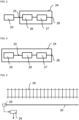
- monitoring signals for monitoring a railway track 29 are shown.
- the distance along the railway track 29 is plotted in arbitrary units.
- the y-axis the time is plotted in arbitrary units along the arrow, this means from top to bottom.
- the third axis is not shown in this two-dimensional representation, however, the lines shown in the diagram are monitoring signals detected by the distributed acoustic sensor 20 arranged along the railway track 29.
- the five lines represent the signal that is detected by the distributed acoustic sensor 20 along a distance of the railway track 29 over a certain period of time.
- the five lines only schematically represent the shape of the signal. Under normal conditions nearly no distinct features can be discriminated in the monitoring signals.
- the amplitude of the monitoring signals is increased at the positions where a rail vehicle moves for the time where the rail vehicle moves at these positions. This means, for the white areas in the diagram the amplitude of the monitoring signals is not increased. Between the five lines the amplitude of the monitoring signals is increased as well. Thus, the movement of a rail vehicle is represented by an area of increased amplitude of the monitoring signals in this diagram.
- the diagram in figure 2 further shows an initial position 21 and three predefined positions 22. For these four positions the monitoring signals have pronounced features 23.
- the initial position 21 is the position that the rail vehicle passes at first out of these four positions.
- the rail can have an irregularity or any other feature that leads to localized vibrations in the moment when a wheel of a rail vehicle passes the initial position 21.
- the first monitoring signal M1 is detected.
- the first monitoring signal M1 comprises five features 23 that can be distinguished from each other. Each of the five features 23 relates to one axle of the rail vehicle passing the initial position 21. Thus, by counting the features 23 in the first monitoring signal M1 the number of axles of the rail vehicle passing the initial position 21 can be determined.
- the integrity of the rail vehicle is given.
- each second monitoring signal M2 comprises five features 23 that can be distinguished from each other.
- Each of the five features 23 relates to one axle of the rail vehicle passing the respective predefined position 22.
- the space between two passing axles can be regarded as a feature 23. In this way, the number of axles of the rail vehicle passing the respective predefined position 22 can be determined as well.
- the rail vehicle has the same number of axles at the initial position 21 and the three predefined positions 22. Therefore, for the three predefined positions 22 the integrity of the rail vehicle is confirmed.
- FIG 3 shows an exemplary embodiment of the monitoring unit 24 for monitoring a railway track 29.
- the monitoring unit 24 comprises an input 25 that is connected to a distributed acoustic sensor 20 being arranged along the track 29.
- the monitoring unit 24 further comprises a detection unit 26 that is configured to receive monitoring signals that are detected by the distributed acoustic sensor 20.
- the detection unit 26 is connected to the input 25.
- the monitoring unit 24 further comprises a comparison unit 27 that is configured to compare the first monitoring signal M1 and the second monitoring signal M2 with each other.
- the comparison unit 27 is connected to the detection unit 26.
- the monitoring unit 24 further comprises an output 28 at which a confirmation signal is provided for the case that the first monitoring signal M1 and the second monitoring signal M2 relate to the same number of axles.
- the comparison unit 27 is connected to the output 28.
- FIG 4 shows another exemplary embodiment of the monitoring unit 24.
- the monitoring unit 24 comprises the distributed acoustic sensor 20 or at least a part of the distributed acoustic sensor 20.
- FIG. 5 shows an exemplary embodiment of the monitoring unit 24 with the distributed acoustic sensor 20.
- the monitoring unit 24 is connected to the distributed acoustic sensor 20.
- the distributed acoustic sensor 20 comprises an optical fibre 30 that is arranged along the track 29. Therefore, the monitoring signals are backscattered signals of an input signal which is provided to the optical fibre 30.
Landscapes
- Engineering & Computer Science (AREA)
- Mechanical Engineering (AREA)
- Health & Medical Sciences (AREA)
- Biomedical Technology (AREA)
- General Health & Medical Sciences (AREA)
- Automation & Control Theory (AREA)
- Train Traffic Observation, Control, And Security (AREA)
Claims (14)
- Verfahren zum Überwachen eines Eisenbahngleises (29), wobei das Verfahren umfasst:- Erfassen eines ersten Überwachungssignals (M1) durch einen verteilten akustischen Sensor (20) an einer Ausgangsposition (21), während ein Schienenfahrzeug die Ausgangsposition (21) durchfährt, wobei der verteilte akustische Sensor (20) entlang des Gleises (29) angeordnet ist,- Erfassen eines zweiten Überwachungssignals (M2) durch den verteilten akustischen Sensor (20) an mindestens einer vordefinierten Position (22) entlang des Gleises (29), während ein Schienenfahrzeug die vordefinierte Position (22) durchfährt,- Vergleichen des ersten Überwachungssignals (M1) und des zweiten Überwachungssignals (M2) miteinander, wobei- das erste Überwachungssignal (M1) Merkmale (23) umfasst, die sich jeweils auf eine Achse des die Ausgangsposition (21) durchfahrenden Schienenfahrzeugs beziehen, wobei jedes Merkmal (23) des ersten Überwachungssignals (M1) während der Durchfahrt einer der Achsen des durchfahrenden Schienenfahrzeugs an der Ausgangsposition (21) erfasst wird, und das zweite Überwachungssignal (M2) Merkmale (23) umfasst, die sich jeweils auf eine Achse des die vordefinierte Position (22) durchfahrenden Schienenfahrzeugs beziehen, wobei jedes Merkmal (23) des zweiten Überwachungssignals (M2) während der Durchfahrt einer der Achsen des durchfahrenden Schienenfahrzeugs an der vordefinierten Position (22) erfasst wird,- wobei das Vergleichen des ersten Überwachungssignals (M1) und des zweiten Überwachungssignals (M2) miteinander umfasst, die Merkmale (23), die sich auf die Achsen des jeweiligen durchfahrenden Schienenfahrzeugs beziehen für das erste Überwachungssignal (M1) und das zweite Überwachungssignal (M2) zu zählen, und- der verteilte akustische Sensor (20) eine optische Faser (30) umfasst, die entlang des Gleises (29) angeordnet ist, und die Überwachungssignale rückgestreute Signale eines Eingangssignals sind, das der optischen Faser (30) bereitgestellt wird.
- Verfahren zum Überwachen eines Eisenbahngleises (29) nach dem vorhergehenden Anspruch, wobei das Vergleichen des ersten Überwachungssignals (M1) und des zweiten Überwachungssignals (M2) miteinander darüber hinaus umfasst, eine Korrelation zwischen dem ersten Überwachungssignal (M1) und dem zweiten Überwachungssignal (M2) zu berechnen.
- Verfahren zum Überwachen eines Eisenbahngleises (29) nach einem der vorhergehenden Ansprüche, wobei in der Ausgangsposition (21) die Integrität des die Ausgangsposition (21) durchfahrenden Schienenfahrzeugs gegeben ist.
- Verfahren zum Überwachen eines Eisenbahngleises (29) nach dem vorherigen Anspruch, wobei die Integrität des die Ausgangsposition (21) durchfahrenden Schienenfahrzeugs durch Personal des jeweiligen Schienenfahrzeugs oder durch eine externe Vorrichtung bestätigt wird.
- Verfahren zum Überwachen eines Eisenbahngleises (29) nach einem der Ansprüche 3 oder 4, wobei die Integrität des die Ausgangsposition (21) durchfahrenden Schienenfahrzeugs für den Fall bestätigt wird, dass das erste Überwachungssignal (M1) dieselbe Anzahl von Merkmalen (23) umfasst, die sich jeweils auf eine Achse des die Ausgangsposition (21) durchfahrenden Schienenfahrzeugs beziehen, wie ein vorheriges Überwachungssignal, für das die Integrität des die Position durchfahrenden Schienenfahrzeugs, wo das vorherige Überwachungssignal erfasst wird, durch Personal des jeweiligen Schienenfahrzeugs oder durch eine externe Vorrichtung bestätigt wird.
- Verfahren zum Überwachen eines Eisenbahngleises (29) nach einem der vorhergehenden Ansprüche, wobei die Position eines sich auf dem Gleis (29) bewegenden Schienenfahrzeugs bereitgestellt wird.
- Verfahren zum Überwachen eines Eisenbahngleises (29) nach einem der vorhergehenden Ansprüche, wobei ein Bestätigungssignal bereitgestellt wird, wenn das erste Überwachungssignal (M1) und das zweite Überwachungssignal (M2) sich auf dieselbe Anzahl von Achsen des jeweiligen durchfahrenden Schienenfahrzeugs beziehen.
- Verfahren zum Überwachen eines Eisenbahngleises (29) nach einem der vorhergehenden Ansprüche, wobei ein Bestätigungssignal bereitgestellt wird, wenn das erste Überwachungssignal (M1) und das zweite Überwachungssignal (M2) mindestens einen vordefinierten Grad an Korrelation haben.
- Verfahren zum Überwachen eines Eisenbahngleises (29) nach einem der vorhergehenden Ansprüche, wobei die mindestens eine vordefinierte Position (22) bestimmt wird, indem eine Korrelationsanalyse für Überwachungssignale durchgeführt wird, die an mehreren Positionen entlang des Gleises (29) während der Durchfahrt eines Schienenfahrzeugs mit dem ersten Überwachungssignal erfasst werden, wobei eine Position entlang des Gleises (29) eine vordefinierte Position (22) ist, wenn das Überwachungssignal an der jeweiligen Position mindestens einen vordefinierten Korrelationskoeffizient mit dem ersten Überwachungssignal (M1) hat.
- Verfahren zum Überwachen eines Eisenbahngleises (29) nach einem der vorhergehenden Ansprüche, wobei an der vordefinierten Position (22) die Schiene einen Defekt oder eine Irregularität hat.
- Verfahren zum Überwachen eines Eisenbahngleises (29) nach einem der vorhergehenden Ansprüche, wobei das zweite Überwachungssignal (M2) eine Amplitude hat, die über einer vordefinierten Schwelle liegt, und Überwachungssignale, die während der Durchfahrt eines Schienenfahrzeugs an Positionen erfasst werden, die sich von der mindestens einen vordefinierten Position (22) unterscheiden, eine Amplitude haben, die unter der vordefinierten Schwelle liegt.
- Verfahren zum Überwachen eines Eisenbahngleises (29) nach einem der vorhergehenden Ansprüche, wobei das Verfahren für mehrere vordefinierte Positionen (22) durchgeführt wird.
- Überwachungseinheit (24) zum Überwachen eines Eisenbahngleises (29), wobei die Überwachungseinheit (24) umfasst:- einen Eingang (25), der an einen verteilten akustischen Sensor (20) anschließbar ist, der entlang des Gleises (29) angeordnet ist,- eine Erfassungseinheit (26), die dazu ausgelegt ist, Überwachungssignale zu empfangen, die durch den verteilten akustischen Sensor (20) erfasst werden,- eine Vergleichseinheit (27), die dazu ausgelegt ist, ein erstes Überwachungssignal (M1), das durch den verteilten akustischen Sensor (20) an einer Ausgangsposition erfasst wird, während ein Schienenfahrzeug die Ausgangsposition (21) durchfährt, und ein zweites Überwachungssignal (M2) miteinander zu vergleichen, das durch den verteilten akustischen Sensor (20) an mindestens einer vordefinierten Position (22) entlang des Gleises (29) erfasst wird, während ein Schienenfahrzeug die vordefinierte Position (22) durchfährt, wobei- das erste Überwachungssignal (M1) Merkmale (23) umfasst, die sich jeweils auf eine Achse des die Ausgangsposition (21) durchfahrenden Schienenfahrzeugs beziehen, wobei jedes Merkmal (23) des ersten Überwachungssignals (M1) während der Durchfahrt einer der Achsen des durchfahrenden Schienenfahrzeugs an der Ausgangsposition (21) erfasst wird, und das zwei Überwachungssignal (M2) Merkmale (23) umfasst, die sich jeweils auf eine Achse des die vordefinierte Position (22) durchfahrenden Schienenfahrzeugs beziehen, wobei jedes Merkmal (23) des zweiten Überwachungssignals (M2) während der Durchfahrt einer der Achsen des durchfahrenden Schienenfahrzeugs an der vordefinierten Position (22) erfasst wird,- wobei das Vergleichen des ersten Überwachungssignals (M1) und des zweiten Überwachungssignals (M2) miteinander umfasst, die Merkmale (23), die sich auf die Achsen des jeweiligen durchfahrenden Schienenfahrzeugs beziehen, für das erste Überwachungssignal (M1) und das zweite Überwachungssignal (M2) zu zählen, und- der verteilte akustische Sensor (20) eine optische Faser (30) umfasst, die entlang des Gleises (29) angeordnet ist, und die Überwachungssignale rückgestreute Signale eines Eingangssignals, sind, das der optischen Faser (30) bereitgestellt wird.
- Überwachungseinheit (24) nach dem vorhergehenden Anspruch, wobei die Überwachungseinheit (24) darüber hinaus einen Ausgang (28) umfasst, an dem ein Bestätigungssignal für den Fall bereitgestellt wird, dass sich das erste Überwachungssignal (M1) und das zweite Überwachungssignal (M2) auf dieselbe Anzahl von Achsen beziehen.
Priority Applications (10)
| Application Number | Priority Date | Filing Date | Title |
|---|---|---|---|
| PL20200042.8T PL3978331T3 (pl) | 2020-10-05 | 2020-10-05 | Sposób monitorowania toru kolejowego i jednostka monitorująca do monitorowania toru kolejowego |
| HRP20241423TT HRP20241423T1 (hr) | 2020-10-05 | 2020-10-05 | Postupak nadziranja željezničkog kolosijeka i jedinica za nadziranje željezničkog kolosijeka |
| ES20200042T ES2999383T3 (en) | 2020-10-05 | 2020-10-05 | Method for monitoring a railway track and monitoring unit for monitoring a railway track |
| EP20200042.8A EP3978331B8 (de) | 2020-10-05 | 2020-10-05 | Verfahren zur überwachung eines eisenbahngleises und überwachungseinheit zur überwachung eines eisenbahngleises |
| AU2021356025A AU2021356025B2 (en) | 2020-10-05 | 2021-09-30 | Method for monitoring a railway track and monitoring unit for monitoring a railway track |
| US18/247,731 US20230415796A1 (en) | 2020-10-05 | 2021-09-30 | Method for monitoring a railway track and monitoring unit for monitoring a railway track |
| PCT/EP2021/076924 WO2022073842A1 (en) | 2020-10-05 | 2021-09-30 | Method for monitoring a railway track and monitoring unit for monitoring a railway track |
| CN202180068373.0A CN116348358B (zh) | 2020-10-05 | 2021-09-30 | 用于监测铁路轨道的方法和用于监测铁路轨道的监测单元 |
| BR112023004786A BR112023004786A2 (pt) | 2020-10-05 | 2021-09-30 | Método para monitorar uma via férrea e unidade de monitoramento para monitorar uma via férrea |
| ZA2023/04149A ZA202304149B (en) | 2020-10-05 | 2023-04-04 | Method for monitoring a railway track and monitoring unit for monitoring a railway track |
Applications Claiming Priority (1)
| Application Number | Priority Date | Filing Date | Title |
|---|---|---|---|
| EP20200042.8A EP3978331B8 (de) | 2020-10-05 | 2020-10-05 | Verfahren zur überwachung eines eisenbahngleises und überwachungseinheit zur überwachung eines eisenbahngleises |
Publications (3)
| Publication Number | Publication Date |
|---|---|
| EP3978331A1 EP3978331A1 (de) | 2022-04-06 |
| EP3978331B1 true EP3978331B1 (de) | 2024-08-21 |
| EP3978331B8 EP3978331B8 (de) | 2024-10-02 |
Family
ID=72752317
Family Applications (1)
| Application Number | Title | Priority Date | Filing Date |
|---|---|---|---|
| EP20200042.8A Active EP3978331B8 (de) | 2020-10-05 | 2020-10-05 | Verfahren zur überwachung eines eisenbahngleises und überwachungseinheit zur überwachung eines eisenbahngleises |
Country Status (10)
| Country | Link |
|---|---|
| US (1) | US20230415796A1 (de) |
| EP (1) | EP3978331B8 (de) |
| CN (1) | CN116348358B (de) |
| AU (1) | AU2021356025B2 (de) |
| BR (1) | BR112023004786A2 (de) |
| ES (1) | ES2999383T3 (de) |
| HR (1) | HRP20241423T1 (de) |
| PL (1) | PL3978331T3 (de) |
| WO (1) | WO2022073842A1 (de) |
| ZA (1) | ZA202304149B (de) |
Family Cites Families (10)
| Publication number | Priority date | Publication date | Assignee | Title |
|---|---|---|---|---|
| KR100627603B1 (ko) * | 2004-08-30 | 2006-09-25 | 샬롬엔지니어링 주식회사 | 열차자동후부감지장치 |
| ITBN20060004A1 (it) * | 2006-09-20 | 2006-12-20 | Antonello Cutolo | Sistema di trasmissione in fibra ottica per il monitoraggio dei parametri ed il miglioramento della sicurezza di una linea ferroviaria |
| GB201201703D0 (en) * | 2012-02-01 | 2012-03-14 | Qinetiq Ltd | Detecting train separation |
| DE102016210965A1 (de) * | 2016-06-20 | 2017-12-21 | Siemens Aktiengesellschaft | Verfahren zum Betreiben eines spurgebundenen Fahrzeugs sowie Verkehrssystem |
| DE102016210968A1 (de) * | 2016-06-20 | 2017-12-21 | Siemens Aktiengesellschaft | Verfahren zum Betreiben einer Ortungseinrichtung sowie Ortungseinrichtung |
| EP3275763B1 (de) * | 2016-07-27 | 2021-09-15 | Frauscher sensortechnik GmbH | Sensoranordnung zur eisenbahnüberwachung und zugehöriges verfahren |
| CN206255026U (zh) * | 2016-10-24 | 2017-06-16 | 南京派光信息技术有限公司 | 基于分布式光纤列车车厢分离实时预警系统 |
| KR20190064035A (ko) * | 2017-11-30 | 2019-06-10 | (주)넷케이티아이 | 분산음향광센서 기반 철도운행 상태 감시 시스템 및 그 방법 |
| EP3531078A1 (de) * | 2018-02-21 | 2019-08-28 | Frauscher Sensortechnik GmbH | Auswerteeinheit, nachführsystem und verfahren zur auswertung eines digitalen signals |
| CN109606423A (zh) * | 2018-12-10 | 2019-04-12 | 上海电气泰雷兹交通自动化系统有限公司 | 区域控制器及非通信列车完整性判断方法 |
-
2020
- 2020-10-05 ES ES20200042T patent/ES2999383T3/es active Active
- 2020-10-05 PL PL20200042.8T patent/PL3978331T3/pl unknown
- 2020-10-05 HR HRP20241423TT patent/HRP20241423T1/hr unknown
- 2020-10-05 EP EP20200042.8A patent/EP3978331B8/de active Active
-
2021
- 2021-09-30 WO PCT/EP2021/076924 patent/WO2022073842A1/en not_active Ceased
- 2021-09-30 BR BR112023004786A patent/BR112023004786A2/pt unknown
- 2021-09-30 AU AU2021356025A patent/AU2021356025B2/en active Active
- 2021-09-30 CN CN202180068373.0A patent/CN116348358B/zh active Active
- 2021-09-30 US US18/247,731 patent/US20230415796A1/en active Pending
-
2023
- 2023-04-04 ZA ZA2023/04149A patent/ZA202304149B/en unknown
Also Published As
| Publication number | Publication date |
|---|---|
| CN116348358B (zh) | 2026-03-06 |
| AU2021356025A1 (en) | 2023-05-11 |
| US20230415796A1 (en) | 2023-12-28 |
| HRP20241423T1 (hr) | 2024-12-20 |
| EP3978331A1 (de) | 2022-04-06 |
| WO2022073842A1 (en) | 2022-04-14 |
| CN116348358A (zh) | 2023-06-27 |
| ZA202304149B (en) | 2024-12-18 |
| ES2999383T3 (en) | 2025-02-25 |
| EP3978331B8 (de) | 2024-10-02 |
| AU2021356025B2 (en) | 2023-12-21 |
| PL3978331T3 (pl) | 2025-01-20 |
| BR112023004786A2 (pt) | 2023-04-18 |
Similar Documents
| Publication | Publication Date | Title |
|---|---|---|
| EP1097076B1 (de) | Verfahren und vorrichtung zur ermittlung defekter eisenbahnräder | |
| US8985523B2 (en) | Railway system using acoustic monitoring | |
| AU2017301999B2 (en) | Evaluation unit for a sensor arrangement for railway monitoring, sensor arrangement and corresponding method | |
| EP0227661B1 (de) | Verfahren und vorrichtung zum auffinden von verformten laufflächen an eisenbahnfahrzeugrädern | |
| RU2619148C2 (ru) | Определение саморасцепа железнодорожного состава | |
| CN108290585B (zh) | 用于以比较控制方式检测脱轨的方法和设备 | |
| US12600389B2 (en) | Method for monitoring a railway track and monitoring system for monitoring a railway track | |
| EP3910301B1 (de) | Schienenbruchbestimmungssystem und verfahren zur bestimmung des schienenbruchs unter verwendung davon | |
| EP3978331B1 (de) | Verfahren zur überwachung eines eisenbahngleises und überwachungseinheit zur überwachung eines eisenbahngleises | |
| US11674826B2 (en) | Monitoring unit for monitoring a linear asset and method for monitoring a linear asset | |
| JP4118780B2 (ja) | 車両の異常検出システム及び異常検出方法 | |
| JP2008120258A (ja) | 車輪踏面状態の検知システム | |
| EP4086138A1 (de) | Vorrichtung zur induzierung mechanischer schwingungen und verfahren zur induzierung mechanischer schwingungen |
Legal Events
| Date | Code | Title | Description |
|---|---|---|---|
| REG | Reference to a national code |
Ref country code: HR Ref legal event code: TUEP Ref document number: P20241423T Country of ref document: HR |
|
| PUAI | Public reference made under article 153(3) epc to a published international application that has entered the european phase |
Free format text: ORIGINAL CODE: 0009012 |
|
| STAA | Information on the status of an ep patent application or granted ep patent |
Free format text: STATUS: THE APPLICATION HAS BEEN PUBLISHED |
|
| AK | Designated contracting states |
Kind code of ref document: A1 Designated state(s): AL AT BE BG CH CY CZ DE DK EE ES FI FR GB GR HR HU IE IS IT LI LT LU LV MC MK MT NL NO PL PT RO RS SE SI SK SM TR |
|
| STAA | Information on the status of an ep patent application or granted ep patent |
Free format text: STATUS: REQUEST FOR EXAMINATION WAS MADE |
|
| 17P | Request for examination filed |
Effective date: 20220922 |
|
| RBV | Designated contracting states (corrected) |
Designated state(s): AL AT BE BG CH CY CZ DE DK EE ES FI FR GB GR HR HU IE IS IT LI LT LU LV MC MK MT NL NO PL PT RO RS SE SI SK SM TR |
|
| GRAP | Despatch of communication of intention to grant a patent |
Free format text: ORIGINAL CODE: EPIDOSNIGR1 |
|
| STAA | Information on the status of an ep patent application or granted ep patent |
Free format text: STATUS: GRANT OF PATENT IS INTENDED |
|
| RIC1 | Information provided on ipc code assigned before grant |
Ipc: B61L 27/57 20220101ALI20240220BHEP Ipc: B61L 1/16 20060101AFI20240220BHEP |
|
| INTG | Intention to grant announced |
Effective date: 20240315 |
|
| P01 | Opt-out of the competence of the unified patent court (upc) registered |
Effective date: 20240521 |
|
| GRAS | Grant fee paid |
Free format text: ORIGINAL CODE: EPIDOSNIGR3 |
|
| GRAA | (expected) grant |
Free format text: ORIGINAL CODE: 0009210 |
|
| STAA | Information on the status of an ep patent application or granted ep patent |
Free format text: STATUS: THE PATENT HAS BEEN GRANTED |
|
| REG | Reference to a national code |
Ref country code: DE Ref legal event code: R081 Ref document number: 602020036087 Country of ref document: DE Owner name: SENSONIC GMBH, AT Free format text: FORMER OWNER: FRAUSCHER SENSOR TECHNOLOGY GROUP GMBH, ST. MARIENKIRCHEN, AT |
|
| AK | Designated contracting states |
Kind code of ref document: B1 Designated state(s): AL AT BE BG CH CY CZ DE DK EE ES FI FR GB GR HR HU IE IS IT LI LT LU LV MC MK MT NL NO PL PT RO RS SE SI SK SM TR |
|
| REG | Reference to a national code |
Ref country code: GB Ref legal event code: FG4D |
|
| REG | Reference to a national code |
Ref country code: CH Ref legal event code: EP |
|
| RAP2 | Party data changed (patent owner data changed or rights of a patent transferred) |
Owner name: SENSONIC GMBH |
|
| REG | Reference to a national code |
Ref country code: DE Ref legal event code: R096 Ref document number: 602020036087 Country of ref document: DE |
|
| REG | Reference to a national code |
Ref country code: IE Ref legal event code: FG4D |
|
| REG | Reference to a national code |
Ref country code: CH Ref legal event code: PK Free format text: BERICHTIGUNG B8 |
|
| REG | Reference to a national code |
Ref country code: HR Ref legal event code: ODRP Ref document number: P20241423T Country of ref document: HR Payment date: 20241015 Year of fee payment: 5 |
|
| REG | Reference to a national code |
Ref country code: LT Ref legal event code: MG9D |
|
| REG | Reference to a national code |
Ref country code: HR Ref legal event code: T1PR Ref document number: P20241423 Country of ref document: HR |
|
| REG | Reference to a national code |
Ref country code: NL Ref legal event code: MP Effective date: 20240821 |
|
| PG25 | Lapsed in a contracting state [announced via postgrant information from national office to epo] |
Ref country code: NO Free format text: LAPSE BECAUSE OF FAILURE TO SUBMIT A TRANSLATION OF THE DESCRIPTION OR TO PAY THE FEE WITHIN THE PRESCRIBED TIME-LIMIT Effective date: 20241121 |
|
| PG25 | Lapsed in a contracting state [announced via postgrant information from national office to epo] |
Ref country code: NL Free format text: LAPSE BECAUSE OF FAILURE TO SUBMIT A TRANSLATION OF THE DESCRIPTION OR TO PAY THE FEE WITHIN THE PRESCRIBED TIME-LIMIT Effective date: 20240821 Ref country code: FI Free format text: LAPSE BECAUSE OF FAILURE TO SUBMIT A TRANSLATION OF THE DESCRIPTION OR TO PAY THE FEE WITHIN THE PRESCRIBED TIME-LIMIT Effective date: 20240821 Ref country code: GR Free format text: LAPSE BECAUSE OF FAILURE TO SUBMIT A TRANSLATION OF THE DESCRIPTION OR TO PAY THE FEE WITHIN THE PRESCRIBED TIME-LIMIT Effective date: 20241122 Ref country code: PT Free format text: LAPSE BECAUSE OF FAILURE TO SUBMIT A TRANSLATION OF THE DESCRIPTION OR TO PAY THE FEE WITHIN THE PRESCRIBED TIME-LIMIT Effective date: 20241223 |
|
| PG25 | Lapsed in a contracting state [announced via postgrant information from national office to epo] |
Ref country code: BG Free format text: LAPSE BECAUSE OF FAILURE TO SUBMIT A TRANSLATION OF THE DESCRIPTION OR TO PAY THE FEE WITHIN THE PRESCRIBED TIME-LIMIT Effective date: 20240821 |
|
| PG25 | Lapsed in a contracting state [announced via postgrant information from national office to epo] |
Ref country code: LV Free format text: LAPSE BECAUSE OF FAILURE TO SUBMIT A TRANSLATION OF THE DESCRIPTION OR TO PAY THE FEE WITHIN THE PRESCRIBED TIME-LIMIT Effective date: 20240821 |
|
| PG25 | Lapsed in a contracting state [announced via postgrant information from national office to epo] |
Ref country code: IS Free format text: LAPSE BECAUSE OF FAILURE TO SUBMIT A TRANSLATION OF THE DESCRIPTION OR TO PAY THE FEE WITHIN THE PRESCRIBED TIME-LIMIT Effective date: 20241221 |
|
| PG25 | Lapsed in a contracting state [announced via postgrant information from national office to epo] |
Ref country code: RS Free format text: LAPSE BECAUSE OF FAILURE TO SUBMIT A TRANSLATION OF THE DESCRIPTION OR TO PAY THE FEE WITHIN THE PRESCRIBED TIME-LIMIT Effective date: 20241121 |
|
| PG25 | Lapsed in a contracting state [announced via postgrant information from national office to epo] |
Ref country code: RS Free format text: LAPSE BECAUSE OF FAILURE TO SUBMIT A TRANSLATION OF THE DESCRIPTION OR TO PAY THE FEE WITHIN THE PRESCRIBED TIME-LIMIT Effective date: 20241121 Ref country code: PT Free format text: LAPSE BECAUSE OF FAILURE TO SUBMIT A TRANSLATION OF THE DESCRIPTION OR TO PAY THE FEE WITHIN THE PRESCRIBED TIME-LIMIT Effective date: 20241223 Ref country code: NO Free format text: LAPSE BECAUSE OF FAILURE TO SUBMIT A TRANSLATION OF THE DESCRIPTION OR TO PAY THE FEE WITHIN THE PRESCRIBED TIME-LIMIT Effective date: 20241121 Ref country code: NL Free format text: LAPSE BECAUSE OF FAILURE TO SUBMIT A TRANSLATION OF THE DESCRIPTION OR TO PAY THE FEE WITHIN THE PRESCRIBED TIME-LIMIT Effective date: 20240821 Ref country code: LV Free format text: LAPSE BECAUSE OF FAILURE TO SUBMIT A TRANSLATION OF THE DESCRIPTION OR TO PAY THE FEE WITHIN THE PRESCRIBED TIME-LIMIT Effective date: 20240821 Ref country code: IS Free format text: LAPSE BECAUSE OF FAILURE TO SUBMIT A TRANSLATION OF THE DESCRIPTION OR TO PAY THE FEE WITHIN THE PRESCRIBED TIME-LIMIT Effective date: 20241221 Ref country code: GR Free format text: LAPSE BECAUSE OF FAILURE TO SUBMIT A TRANSLATION OF THE DESCRIPTION OR TO PAY THE FEE WITHIN THE PRESCRIBED TIME-LIMIT Effective date: 20241122 Ref country code: FI Free format text: LAPSE BECAUSE OF FAILURE TO SUBMIT A TRANSLATION OF THE DESCRIPTION OR TO PAY THE FEE WITHIN THE PRESCRIBED TIME-LIMIT Effective date: 20240821 Ref country code: BG Free format text: LAPSE BECAUSE OF FAILURE TO SUBMIT A TRANSLATION OF THE DESCRIPTION OR TO PAY THE FEE WITHIN THE PRESCRIBED TIME-LIMIT Effective date: 20240821 |
|
| REG | Reference to a national code |
Ref country code: ES Ref legal event code: FG2A Ref document number: 2999383 Country of ref document: ES Kind code of ref document: T3 Effective date: 20250225 |
|
| PG25 | Lapsed in a contracting state [announced via postgrant information from national office to epo] |
Ref country code: RO Free format text: LAPSE BECAUSE OF FAILURE TO SUBMIT A TRANSLATION OF THE DESCRIPTION OR TO PAY THE FEE WITHIN THE PRESCRIBED TIME-LIMIT Effective date: 20240821 Ref country code: SM Free format text: LAPSE BECAUSE OF FAILURE TO SUBMIT A TRANSLATION OF THE DESCRIPTION OR TO PAY THE FEE WITHIN THE PRESCRIBED TIME-LIMIT Effective date: 20240821 Ref country code: DK Free format text: LAPSE BECAUSE OF FAILURE TO SUBMIT A TRANSLATION OF THE DESCRIPTION OR TO PAY THE FEE WITHIN THE PRESCRIBED TIME-LIMIT Effective date: 20240821 |
|
| PG25 | Lapsed in a contracting state [announced via postgrant information from national office to epo] |
Ref country code: CZ Free format text: LAPSE BECAUSE OF FAILURE TO SUBMIT A TRANSLATION OF THE DESCRIPTION OR TO PAY THE FEE WITHIN THE PRESCRIBED TIME-LIMIT Effective date: 20240821 |
|
| PG25 | Lapsed in a contracting state [announced via postgrant information from national office to epo] |
Ref country code: IT Free format text: LAPSE BECAUSE OF FAILURE TO SUBMIT A TRANSLATION OF THE DESCRIPTION OR TO PAY THE FEE WITHIN THE PRESCRIBED TIME-LIMIT Effective date: 20240821 Ref country code: SK Free format text: LAPSE BECAUSE OF FAILURE TO SUBMIT A TRANSLATION OF THE DESCRIPTION OR TO PAY THE FEE WITHIN THE PRESCRIBED TIME-LIMIT Effective date: 20240821 |
|
| REG | Reference to a national code |
Ref country code: DE Ref legal event code: R097 Ref document number: 602020036087 Country of ref document: DE |
|
| PLBE | No opposition filed within time limit |
Free format text: ORIGINAL CODE: 0009261 |
|
| STAA | Information on the status of an ep patent application or granted ep patent |
Free format text: STATUS: NO OPPOSITION FILED WITHIN TIME LIMIT |
|
| PG25 | Lapsed in a contracting state [announced via postgrant information from national office to epo] |
Ref country code: MC Free format text: LAPSE BECAUSE OF FAILURE TO SUBMIT A TRANSLATION OF THE DESCRIPTION OR TO PAY THE FEE WITHIN THE PRESCRIBED TIME-LIMIT Effective date: 20240821 |
|
| PG25 | Lapsed in a contracting state [announced via postgrant information from national office to epo] |
Ref country code: LU Free format text: LAPSE BECAUSE OF NON-PAYMENT OF DUE FEES Effective date: 20241005 Ref country code: BE Free format text: LAPSE BECAUSE OF NON-PAYMENT OF DUE FEES Effective date: 20241031 |
|
| 26N | No opposition filed |
Effective date: 20250522 |
|
| REG | Reference to a national code |
Ref country code: BE Ref legal event code: MM Effective date: 20241031 |
|
| PG25 | Lapsed in a contracting state [announced via postgrant information from national office to epo] |
Ref country code: SE Free format text: LAPSE BECAUSE OF FAILURE TO SUBMIT A TRANSLATION OF THE DESCRIPTION OR TO PAY THE FEE WITHIN THE PRESCRIBED TIME-LIMIT Effective date: 20240821 |
|
| PGFP | Annual fee paid to national office [announced via postgrant information from national office to epo] |
Ref country code: PL Payment date: 20250924 Year of fee payment: 6 |
|
| PGFP | Annual fee paid to national office [announced via postgrant information from national office to epo] |
Ref country code: HR Payment date: 20250929 Year of fee payment: 6 |
|
| REG | Reference to a national code |
Ref country code: HR Ref legal event code: ODRP Ref document number: P20241423 Country of ref document: HR Payment date: 20250929 Year of fee payment: 6 |
|
| REG | Reference to a national code |
Ref country code: CH Ref legal event code: U11 Free format text: ST27 STATUS EVENT CODE: U-0-0-U10-U11 (AS PROVIDED BY THE NATIONAL OFFICE) Effective date: 20251101 |
|
| PGFP | Annual fee paid to national office [announced via postgrant information from national office to epo] |
Ref country code: DE Payment date: 20251024 Year of fee payment: 6 |
|
| PGFP | Annual fee paid to national office [announced via postgrant information from national office to epo] |
Ref country code: GB Payment date: 20251024 Year of fee payment: 6 |
|
| PGFP | Annual fee paid to national office [announced via postgrant information from national office to epo] |
Ref country code: AT Payment date: 20251021 Year of fee payment: 6 |
|
| PGFP | Annual fee paid to national office [announced via postgrant information from national office to epo] |
Ref country code: FR Payment date: 20251029 Year of fee payment: 6 |
|
| PGFP | Annual fee paid to national office [announced via postgrant information from national office to epo] |
Ref country code: CH Payment date: 20251101 Year of fee payment: 6 |
|
| PGFP | Annual fee paid to national office [announced via postgrant information from national office to epo] |
Ref country code: IE Payment date: 20251021 Year of fee payment: 6 |
|
| PG25 | Lapsed in a contracting state [announced via postgrant information from national office to epo] |
Ref country code: CY Free format text: LAPSE BECAUSE OF FAILURE TO SUBMIT A TRANSLATION OF THE DESCRIPTION OR TO PAY THE FEE WITHIN THE PRESCRIBED TIME-LIMIT; INVALID AB INITIO Effective date: 20201005 |
|
| PGFP | Annual fee paid to national office [announced via postgrant information from national office to epo] |
Ref country code: ES Payment date: 20251114 Year of fee payment: 6 |
|
| REG | Reference to a national code |
Ref country code: AT Ref legal event code: UEP Ref document number: 1715247 Country of ref document: AT Kind code of ref document: T Effective date: 20240821 |
|
| PG25 | Lapsed in a contracting state [announced via postgrant information from national office to epo] |
Ref country code: HU Free format text: LAPSE BECAUSE OF FAILURE TO SUBMIT A TRANSLATION OF THE DESCRIPTION OR TO PAY THE FEE WITHIN THE PRESCRIBED TIME-LIMIT; INVALID AB INITIO Effective date: 20201005 |