EP3978221B1 - Vorrichtung und verfahren zum umformen von kunststoffvorformlingen zu kunststoffbehältnissen mit verbesserter spülstangenanordnung - Google Patents
Vorrichtung und verfahren zum umformen von kunststoffvorformlingen zu kunststoffbehältnissen mit verbesserter spülstangenanordnung Download PDFInfo
- Publication number
- EP3978221B1 EP3978221B1 EP21195858.2A EP21195858A EP3978221B1 EP 3978221 B1 EP3978221 B1 EP 3978221B1 EP 21195858 A EP21195858 A EP 21195858A EP 3978221 B1 EP3978221 B1 EP 3978221B1
- Authority
- EP
- European Patent Office
- Prior art keywords
- rod
- plastic preforms
- plastic
- valve device
- forming
- Prior art date
- Legal status (The legal status is an assumption and is not a legal conclusion. Google has not performed a legal analysis and makes no representation as to the accuracy of the status listed.)
- Active
Links
Images


Classifications
-
- B—PERFORMING OPERATIONS; TRANSPORTING
- B29—WORKING OF PLASTICS; WORKING OF SUBSTANCES IN A PLASTIC STATE IN GENERAL
- B29C—SHAPING OR JOINING OF PLASTICS; SHAPING OF MATERIAL IN A PLASTIC STATE, NOT OTHERWISE PROVIDED FOR; AFTER-TREATMENT OF THE SHAPED PRODUCTS, e.g. REPAIRING
- B29C49/00—Blow-moulding, i.e. blowing a preform or parison to a desired shape within a mould; Apparatus therefor
- B29C49/42—Component parts, details or accessories; Auxiliary operations
- B29C49/4289—Valve constructions or configurations, e.g. arranged to reduce blowing fluid consumption
-
- B—PERFORMING OPERATIONS; TRANSPORTING
- B29—WORKING OF PLASTICS; WORKING OF SUBSTANCES IN A PLASTIC STATE IN GENERAL
- B29C—SHAPING OR JOINING OF PLASTICS; SHAPING OF MATERIAL IN A PLASTIC STATE, NOT OTHERWISE PROVIDED FOR; AFTER-TREATMENT OF THE SHAPED PRODUCTS, e.g. REPAIRING
- B29C49/00—Blow-moulding, i.e. blowing a preform or parison to a desired shape within a mould; Apparatus therefor
- B29C49/08—Biaxial stretching during blow-moulding
- B29C49/10—Biaxial stretching during blow-moulding using mechanical means for prestretching
- B29C49/12—Stretching rods
-
- B—PERFORMING OPERATIONS; TRANSPORTING
- B29—WORKING OF PLASTICS; WORKING OF SUBSTANCES IN A PLASTIC STATE IN GENERAL
- B29C—SHAPING OR JOINING OF PLASTICS; SHAPING OF MATERIAL IN A PLASTIC STATE, NOT OTHERWISE PROVIDED FOR; AFTER-TREATMENT OF THE SHAPED PRODUCTS, e.g. REPAIRING
- B29C49/00—Blow-moulding, i.e. blowing a preform or parison to a desired shape within a mould; Apparatus therefor
- B29C49/42—Component parts, details or accessories; Auxiliary operations
- B29C49/58—Blowing means
-
- B—PERFORMING OPERATIONS; TRANSPORTING
- B29—WORKING OF PLASTICS; WORKING OF SUBSTANCES IN A PLASTIC STATE IN GENERAL
- B29C—SHAPING OR JOINING OF PLASTICS; SHAPING OF MATERIAL IN A PLASTIC STATE, NOT OTHERWISE PROVIDED FOR; AFTER-TREATMENT OF THE SHAPED PRODUCTS, e.g. REPAIRING
- B29C49/00—Blow-moulding, i.e. blowing a preform or parison to a desired shape within a mould; Apparatus therefor
- B29C49/42—Component parts, details or accessories; Auxiliary operations
- B29C49/62—Venting means
- B29C2049/6271—Venting means for venting blowing medium, e.g. using damper or silencer
-
- B—PERFORMING OPERATIONS; TRANSPORTING
- B29—WORKING OF PLASTICS; WORKING OF SUBSTANCES IN A PLASTIC STATE IN GENERAL
- B29C—SHAPING OR JOINING OF PLASTICS; SHAPING OF MATERIAL IN A PLASTIC STATE, NOT OTHERWISE PROVIDED FOR; AFTER-TREATMENT OF THE SHAPED PRODUCTS, e.g. REPAIRING
- B29C2949/00—Indexing scheme relating to blow-moulding
- B29C2949/07—Preforms or parisons characterised by their configuration
- B29C2949/0715—Preforms or parisons characterised by their configuration the preform having one end closed
-
- B—PERFORMING OPERATIONS; TRANSPORTING
- B29—WORKING OF PLASTICS; WORKING OF SUBSTANCES IN A PLASTIC STATE IN GENERAL
- B29C—SHAPING OR JOINING OF PLASTICS; SHAPING OF MATERIAL IN A PLASTIC STATE, NOT OTHERWISE PROVIDED FOR; AFTER-TREATMENT OF THE SHAPED PRODUCTS, e.g. REPAIRING
- B29C49/00—Blow-moulding, i.e. blowing a preform or parison to a desired shape within a mould; Apparatus therefor
- B29C49/02—Combined blow-moulding and manufacture of the preform or the parison
- B29C49/06—Injection blow-moulding
-
- B—PERFORMING OPERATIONS; TRANSPORTING
- B29—WORKING OF PLASTICS; WORKING OF SUBSTANCES IN A PLASTIC STATE IN GENERAL
- B29C—SHAPING OR JOINING OF PLASTICS; SHAPING OF MATERIAL IN A PLASTIC STATE, NOT OTHERWISE PROVIDED FOR; AFTER-TREATMENT OF THE SHAPED PRODUCTS, e.g. REPAIRING
- B29C49/00—Blow-moulding, i.e. blowing a preform or parison to a desired shape within a mould; Apparatus therefor
- B29C49/08—Biaxial stretching during blow-moulding
- B29C49/10—Biaxial stretching during blow-moulding using mechanical means for prestretching
- B29C49/12—Stretching rods
- B29C49/121—Stretching rod configuration, e.g. geometry; Stretching rod material
- B29C49/1212—Stretching rod configuration, e.g. geometry; Stretching rod material the stretching rod comprising at least one opening on the surface, e.g. through which compressed air is blown into the preform to expand the same
-
- B—PERFORMING OPERATIONS; TRANSPORTING
- B29—WORKING OF PLASTICS; WORKING OF SUBSTANCES IN A PLASTIC STATE IN GENERAL
- B29C—SHAPING OR JOINING OF PLASTICS; SHAPING OF MATERIAL IN A PLASTIC STATE, NOT OTHERWISE PROVIDED FOR; AFTER-TREATMENT OF THE SHAPED PRODUCTS, e.g. REPAIRING
- B29C49/00—Blow-moulding, i.e. blowing a preform or parison to a desired shape within a mould; Apparatus therefor
- B29C49/08—Biaxial stretching during blow-moulding
- B29C49/10—Biaxial stretching during blow-moulding using mechanical means for prestretching
- B29C49/12—Stretching rods
- B29C49/121—Stretching rod configuration, e.g. geometry; Stretching rod material
- B29C49/1215—Geometry of the stretching rod, e.g. specific stretching rod end shape
-
- B—PERFORMING OPERATIONS; TRANSPORTING
- B29—WORKING OF PLASTICS; WORKING OF SUBSTANCES IN A PLASTIC STATE IN GENERAL
- B29C—SHAPING OR JOINING OF PLASTICS; SHAPING OF MATERIAL IN A PLASTIC STATE, NOT OTHERWISE PROVIDED FOR; AFTER-TREATMENT OF THE SHAPED PRODUCTS, e.g. REPAIRING
- B29C49/00—Blow-moulding, i.e. blowing a preform or parison to a desired shape within a mould; Apparatus therefor
- B29C49/42—Component parts, details or accessories; Auxiliary operations
- B29C49/4284—Means for recycling or reusing auxiliaries or materials, e.g. blowing fluids or energy
- B29C49/42845—Recycling or reusing of fluid, e.g. pressure
- B29C49/42855—Blowing fluids, e.g. reducing fluid consumption
-
- B—PERFORMING OPERATIONS; TRANSPORTING
- B29—WORKING OF PLASTICS; WORKING OF SUBSTANCES IN A PLASTIC STATE IN GENERAL
- B29C—SHAPING OR JOINING OF PLASTICS; SHAPING OF MATERIAL IN A PLASTIC STATE, NOT OTHERWISE PROVIDED FOR; AFTER-TREATMENT OF THE SHAPED PRODUCTS, e.g. REPAIRING
- B29C49/00—Blow-moulding, i.e. blowing a preform or parison to a desired shape within a mould; Apparatus therefor
- B29C49/42—Component parts, details or accessories; Auxiliary operations
- B29C49/4284—Means for recycling or reusing auxiliaries or materials, e.g. blowing fluids or energy
- B29C49/4286—Recycling or reusing of heat energy
-
- B—PERFORMING OPERATIONS; TRANSPORTING
- B29—WORKING OF PLASTICS; WORKING OF SUBSTANCES IN A PLASTIC STATE IN GENERAL
- B29K—INDEXING SCHEME ASSOCIATED WITH SUBCLASSES B29B, B29C OR B29D, RELATING TO MOULDING MATERIALS OR TO MATERIALS FOR MOULDS, REINFORCEMENTS, FILLERS OR PREFORMED PARTS, e.g. INSERTS
- B29K2067/00—Use of polyesters or derivatives thereof, as moulding material
- B29K2067/003—PET, i.e. poylethylene terephthalate
-
- B—PERFORMING OPERATIONS; TRANSPORTING
- B29—WORKING OF PLASTICS; WORKING OF SUBSTANCES IN A PLASTIC STATE IN GENERAL
- B29L—INDEXING SCHEME ASSOCIATED WITH SUBCLASS B29C, RELATING TO PARTICULAR ARTICLES
- B29L2031/00—Other particular articles
- B29L2031/712—Containers; Packaging elements or accessories, Packages
- B29L2031/7158—Bottles
-
- Y—GENERAL TAGGING OF NEW TECHNOLOGICAL DEVELOPMENTS; GENERAL TAGGING OF CROSS-SECTIONAL TECHNOLOGIES SPANNING OVER SEVERAL SECTIONS OF THE IPC; TECHNICAL SUBJECTS COVERED BY FORMER USPC CROSS-REFERENCE ART COLLECTIONS [XRACs] AND DIGESTS
- Y02—TECHNOLOGIES OR APPLICATIONS FOR MITIGATION OR ADAPTATION AGAINST CLIMATE CHANGE
- Y02P—CLIMATE CHANGE MITIGATION TECHNOLOGIES IN THE PRODUCTION OR PROCESSING OF GOODS
- Y02P70/00—Climate change mitigation technologies in the production process for final industrial or consumer products
- Y02P70/10—Greenhouse gas [GHG] capture, material saving, heat recovery or other energy efficient measures, e.g. motor control, characterised by manufacturing processes, e.g. for rolling metal or metal working
Definitions
- the present invention relates to a device in a method for forming plastic preforms into plastic containers.
- Such devices and methods have long been known from the prior art, for example in the patent specifications US6485669B1 , US2018/134537A1 , DE102009061262B3 and EP2987612A1 described.
- stretch rods are used, which also stretch the plastic preforms in their longitudinal direction during the expansion process.
- systems are also known in which these stretch rods are designed as flushing rods, for example have an air guide channel so that air can be directed directly to the bottom of the container even during the expansion process.
- the bottom center of the shaped bottle is actively cooled in blow molding machines known from the prior art. Through this process, the dimensional stability of the bottle or container is achieved in a shorter time and higher machine performance is possible.
- Purging air is also used in the so-called heat set process to actively cool certain areas of the container after they have been formed and thus ensure dimensional stability in a shorter time.
- a purge air unit on a stretching module of a blowing station.
- a stationary purge air valve is usually provided, as well as a working air line and the cooling and/or purging rod moved by a stretching motor.
- This cooling or flushing rod is drilled hollow. The working air coming from the purge air valve is guided via the hose through the hole to the bottom center of the container or plastic preform to be expanded.
- the dead space volume is made up of the pipe volume and the volume of the flush rod hole. This volume is additionally consumed with each blowing process. In this way, the air consumption of the machine is increased and the economic efficiency for the customer is reduced due to high operating costs.
- the cooling rods are designed as a cylindrical tube, which is usually made from a high-strength stainless steel round material using deep hole drilling. This means that the cooling rods have a diameter ratio of inner diameter to outer diameter of more than 60% over at least 40% of their length due to the technical limitations of the manufacturing processes. Typical lengths for such cooling rods are between 600 and 900 mm.
- the high diameter ratio creates large spaces filled with flushing fluid over large parts of the rod-like bodies or cooling rods and therefore considerable dead spaces. In this way, air consumption in the system increases. Furthermore, due to the slim design of the cooling rods and their axial compressive stress, they are very susceptible to kinks. The large ratio between the inside and outside diameters further exacerbates this problem. For this reason, stronger or harder but also more expensive stainless steel alloys are usually used as starting material in the prior art.
- the present invention is therefore based on the object of reducing and/or avoiding the dead space in such processes and/or reducing the air consumption for the expansion of the containers.
- more stable and less susceptible to damage devices should also be created.
- this valve device is arranged on the movement device and/or the ratio between an inside diameter of the rod-like body and the outside diameter of the rod-like body is at least partially and preferably completely less than or equal to 0.5.
- this valve device is not arranged stationary as before, but directly on the moving parts, which also move the rod-like bodies (hereinafter also referred to as the stretch rod). In this way, longer connecting lines can be saved and thus also dead space volume.
- the second suggestion relates to the stretching or rinsing rod, or the rod-like body itself, and suggests reducing its internal volume.
- the position of the flushing air valve i.e. the valve device, is changed.
- valve is attached directly to the movement device, for example a stretching carriage. In this way, the shut-off point of the purge air is moved closer to the purge air outlet at the selected points of the container, thereby significantly reducing the dead space volume.
- Working air is preferably supplied to the purge air valve via a working air supply. If the purge air valve still requires control air, this can also be transferred via a control air supply, for example from a low-pressure distribution of the blowing station to the purge air valve, which is preferably arranged on a stretching carriage. Furthermore, the control air can also be generated directly on the stretching carriage, for example from the working air by means of a pressure reduction. With this variant, only the working air supply is required.
- a cooling rod is used, which particularly preferably consists of a seamlessly drawn tube which has a ratio of less than or equal to 0.5 between the inner diameter and the outer circumference.
- a semi-finished product made of steel can also be used.
- it is a low-alloy steel, which preferably has a coating. This coating can also optimize corrosion properties and conductive properties.
- the ratio between the inside diameter and the outside diameter in at least 50% of the rod-like body is less than 0.5, preferably at least 60%, preferably at least 70%, preferably at least 80% and preferably at least 90% and particularly preferably above the entire length of the rod-like body.
- the ratio between the inside diameter and the outside diameter is preferably less than 0.48, preferably less than 0.45, preferably less than 0.43, preferably less than 0.41, preferably less than 0.4 and preferably less than 0.38 .
- the rod-like body is particularly preferably a tube and in particular a cylindrical tube.
- the procedures described here can reduce the overall dead space.
- the movement device has a carriage which moves in a longitudinal direction and in particular a longitudinal direction of the rod-like body.
- this longitudinal direction is also a longitudinal direction of the plastic preform to be expanded.
- the rod-like body is particularly preferably also a stretch rod, that is to say the rod-like body preferably also performs the function of stretching the plastic preform in its longitudinal direction.
- the above-mentioned blow mold parts are arranged on blow mold support parts. These can be opened and closed in particular to insert a plastic preform into the blow mold and to remove a manufactured container from the blow mold.
- the device has a carrier and in particular a rotatable carrier on which a plurality of forming stations are arranged. All of these forming stations preferably each have blow molds and the rod-like bodies described here.
- the flowable medium described above is preferably air and in particular compressed air.
- the flowable medium it would also be possible for the flowable medium to be a liquid, for example the container being both expanded and filled with the medium to be filled.
- the valve device is arranged close to the rod-like body.
- the rod-like body can already be inserted into a housing of the valve device. In this way the dead space can be reduced even further.
- the rod-like body has a front or end opening for rinsing the plastic containers. This opening is arranged here in particular on the end side which is opposite the valve device and the channel extends from the valve device to this opening.
- the application device described above is preferably a blowing nozzle.
- this is a loading device which is applied to the mouth of the plastic preform to expand.
- the plastic preform described here is preferably subjected to several pressure levels, such as a pre-blow pressure, an intermediate blow pressure and a finished blow pressure.
- a length of the rod-like body is greater than 300 mm, preferably greater than 400 mm, preferably greater than 500 mm, preferably greater than 550 mm and preferably greater than 600 mm. In a further preferred embodiment, the length of the rod-like body is less than 1500 mm, preferably less than 1300 mm, preferably less than 1200 mm, preferably less than 1000 mm and preferably less than 900 mm.
- a movement of the valve device is at least temporarily and preferably completely coupled to the movement of the rod-like body, i.e. the stretching rod. It is thus possible for the valve device and the rod-like body to be arranged on the same carrier.
- valve device is designed to be pressure-balanced. This configuration offers the advantage that only those forces are used to safely shut off a working air line. In this way the valve can be made very small and light. A horizontal sled and the moving mass can also be kept very small.
- the valve device could have a biasing device that only opens and/or closes at a certain pressure.
- the valve device is therefore designed such that one side of the valve piston, in particular its rear side, is also subjected to a predetermined pressure.
- the piston forces on the sealing side of the piston and the side facing away from the seal are preferably chosen to be essentially the same size or the same size. (Preferably, these piston forces differ from each other by not more than 30%, preferably not more than 20%, preferably not more than 10% and preferably not more than 5%.
- the valve device is a pneumatically operated valve.
- a control air supply is also provided, which serves to actuate the valve device.
- this control air can also be branched off from a working air line in a pressure-reduced form.
- the valve device is preferably arranged on a section of the rod-like body and in particular on an end section. It is thus possible for an output of the valve device to be connected directly to the rod-like body in order to further reduce dead space.
- the rod-like body is made of a metal and in particular of a steel. In this way, the stability of the rod-like body can be increased.
- the rod-like body is coated at least at intervals and in particular is coated at least at intervals on its outer surface.
- the rod-like body is preferably coated on its entire outer surface and/or also on its inner surface. This coating can, for example, achieve anti-corrosion properties and/or a coating that increases the sliding properties of the rod-like body.
- the rod-like body extends through an application device such as a blowing nozzle, at least in one working operation.
- a coating on the body can improve the sliding properties of the rod-like body.
- the rod-like body is particularly preferably coated with a substance which is selected from a group of substances which contains chromium, nickel and/or plastic.
- the material of the rod-like body is a semi-finished product.
- a semi-finished product generally refers to a primary material, i.e. a prefabricated raw material and/or workpieces or semi-finished products of a simple form. These usually consist of a single material that has only been given a basic geometric shape, for example a cylindrical shape.
- the semi-finished product can be a profile steel.
- the procedure described here with regard to the rod-like body can achieve a reduction in the dead space volume in the purge air system.
- the costs for production can also be reduced because the starting material steel is cheaper than the stainless steel compounds mentioned above.
- the stability of the rod-like body can also be improved.
- the present invention is further directed to a rod-like body for stretching plastic preforms, in particular in their longitudinal direction, wherein the rod-like body has a channel for conducting a flowable medium (and in particular the rod-like body has a bore extending in its longitudinal direction) and the rod-like body has a predetermined outer diameter and a predetermined inner diameter and the rod-like body has a length that is between 500 and 1000 mm.
- the rod-like body is made of one part and in particular of steel so that a ratio between the inside diameter and the outside diameter is less than or equal to 0.5.
- a ratio between the inside and outside diameters of less than 0.5 is therefore required for the rod-like body, which is used in particular as a stretching rod.
- the inner diameter of the rod-like body is preferably also the diameter of the channel for guiding the flowable medium.
- the rod-like body preferably has at least one and preferably two end openings and/or the channel extends completely in the longitudinal direction through the rod-like body.
- the diameter of the channel is preferably constant over the longitudinal direction of the rod-like body.
- This channel is preferably designed as a bore which extends in the longitudinal direction of the rod-like body, preferably completely in the longitudinal direction.
- This bore preferably has a cylindrical cross section. As mentioned above, the design of this hole can improve the dead space volume of corresponding systems that use this rod-like body.
- the present invention is further directed to a method for forming plastic preforms into plastic containers and in particular plastic bottles, wherein at least one forming station transforms the plastic preforms into the plastic containers by applying a flowable medium and in particular a gaseous medium, and wherein the forming station has a blow mold, which forms a cavity within which the plastic preforms are formed into the plastic containers and wherein the forming station further has an application device which applies the flowable medium to the plastic preforms as well as a rod-like body which is inserted into the plastic preforms via an opening of the plastic preforms and furthermore a movement device for this rod-like body moves in the longitudinal direction of the plastic preforms, in particular to stretch the plastic preforms.
- this rod-like body has a channel for conducting the flowable medium (or the flowable medium is passed through a channel located in the rod-like body) and a valve device of the forming station controls the supply of the flowable medium in this channel.
- this valve device is arranged on the movement device and/or a ratio between an inner diameter of the rod-like body and the outer diameter of the rod-like body is at least partially and preferably completely smaller than 0.5.
- valve is arranged closer to the rod-like body in comparison to the prior art and/or that the latter has the above-mentioned diameter ratios.
- the plastic preforms are formed into containers during transport with a transport device from the forming stations.
- a pressure-compensated valve device is used as the valve device or the valve device is operated in a pressure-compensated manner at least temporarily.
- a flowable medium and in particular air is directed onto a bottom section of a plastic preform and/or plastic container via the rod-like body.
- the plastic container is acted upon after it has already been completely formed into a plastic bottle within the blow mold.
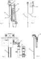
- FIG. 1 shows a schematic representation of a forming device 1 for forming plastic preforms 10 into plastic containers and in particular plastic bottles 40.
- a feed device such as a feed star 32 is provided, which transfers heated plastic preforms to a large number of forming stations 20. These are arranged on a rotatable carrier 25, such as in particular a so-called blowing wheel. In these forming stations, the plastic preforms 10 become the plastic containers 40 and then transported away by a removal device 34, such as a removal star.
- the reference numeral 26 roughly schematically identifies a blow mold that is arranged in the forming station 20.
- This blow mold can have two side parts that can be pivoted relative to one axis to open and close the plastic preforms.
- Figure 2 shows a representation of a forming station 20. This has a rod-like body 24 like a stretching rod, which can be inserted into the interior to stretch the plastic preforms.
- the reference number 4 denotes a movement device which moves this stretching rod for this purpose.
- the reference number 2 denotes an application device which applies a flowable medium and in particular compressed air to the plastic preforms.
- the reference numbers 14a and 14b identify side part supports which are suitable and intended for carrying or holding the blow mold parts of the blow mold 26.
- the reference number 16 denotes a locking device which holds the two blow molded parts or their side part supports 14a and 14b together or locks them together during expansion of the plastic preforms.
- FIG. 3 shows a detailed representation of a forming station according to the state of the art.
- a carrier is provided on which a movement element 52 is arranged.
- the rod-like body 124 is again arranged on this movement element 52.
- Reference numeral 108 denotes a valve device which is connected to the rod-like body via a line 126 such as a hose.
- the interior of this tube forms a dead space volume, which is intended to be reduced according to the invention.
- Figure 4 shows a detailed representation, with only the valve device 108, the line device 126 and the rod-like body 24 being shown here.
- Figure 5 shows a forming station according to the invention.
- a movement element 52 such as a stretching carriage is provided.
- This movement element can be part of the movement device mentioned above.
- the valve device 8 is at However, this embodiment is arranged directly on the rod-like body 24.
- the reference numeral 46 denotes a working air supply line, which is connected to a connection 44 of the valve device 8 via a connecting line 42, which is preferably rigid here. In this way you can access the in Figure 4 Connecting hose 126 shown can be dispensed with and in this way the dead space volume is significantly reduced.
- the valve device is preferably arranged directly on the rod-like body 24. The valve device therefore preferably also moves with the rod-like body 24.
- FIG. 6 a further representation of a forming station according to the invention is shown.
- the reference number 46 refers to a control air supply line in the event that the valve device is designed as a pneumatic valve.
- FIG. 7 shows a detailed representation of an advantageously used valve device, which is designed here as a pressure-balanced valve.
- the reference number 82 denotes the valve device and the reference number 84 denotes a valve seal.
- the reference number 85 denotes a pilot valve, which is used in particular to control the valve device.
- the reference numbers 90 and 92 identify a control chamber and in particular the control chamber controlled by the pilot valve.
- the reference numeral 88 denotes a connection space between a seal side and a piston back, via which the pressure equalization is effected, and the reference numeral 94 denotes the pressure chamber of the piston back.
- Reference number 86 denotes the piston of the valve device.
- Figure 8 shows a sectional view of a rod-like body 24 or a horizontal bar.
- the reference numbers di and da refer to the inside diameter and the outside diameter of this rod-like body. It can be seen that the rod-like body 24 preferably has a cylindrical profile.
- the cavity or channel 62 which is designed here as a bore, is also preferably cylindrical.
Landscapes
- Engineering & Computer Science (AREA)
- Manufacturing & Machinery (AREA)
- Mechanical Engineering (AREA)
- Blow-Moulding Or Thermoforming Of Plastics Or The Like (AREA)
- Processing And Handling Of Plastics And Other Materials For Molding In General (AREA)
Description
- Die vorliegende Erfindung bezieht sich auf eine Vorrichtung in einem Verfahren zum Umformen von Kunststoffvorformlingen zu Kunststoffbehältnissen. Derartige Vorrichtungen und Verfahren sind aus dem Stand der Technik seit Langem bekannt, und beispielsweise in den Patentschriften
US6485669B1 ,US2018/134537A1 ,DE102009061262B3 undEP2987612A1 beschrieben. Dabei ist es ebenfalls aus dem Stand der Technik seit Langem bekannt, dass sogenannte Reckstangen eingesetzt werden, welche die Kunststoffvorformlinge während des Expansionsvorgangs auch in ihrer Längsrichtung dehnen. Daneben sind auch Systeme bekannt, bei denen diese Reckstangen als Spülstangen ausgeführt sind, beispielsweise einen Luftleitkanal haben, damit Luft auch während des Expansionsvorgangs direkt an den Boden des Behältnisses geleitet werden kann. Mit derartigen Spülluftsystemen wird bei aus dem Stand der Technik bekannten Blasmaschinen das Bodenzentrum der ausgeprägten Flasche aktiv gekühlt. Durch diesen Vorgang wird die Formstabilität der Flasche beziehungsweise des Behältnisses in kürzerer Zeit erreicht und es sind höhere Maschinenleistungen möglich. - Auch bei dem sogenannten Heat-Set-Prozess wird Spülluft eingesetzt, um gewisse Bereiche des Behältnisses nach deren Ausprägung aktiv zu kühlen und so die Formstabilität in kürzerer Zeit zu gewährleisten.
- Zu diesem Zweck befindet sich an einem Reckmodul einer Blasstation eine Spüllufteinheit. Dabei ist üblicherweise ein ortsfestes Spülluftventil vorgesehen, sowie auch eine Arbeitsluftleitung und die mit einem Reckmotor bewegte Kühl- und/oder Spülstange. Wie erwähnt ist dabei diese Kühl- oder Spülstange hohl gebohrt. Die von dem Spülluftventil kommende Arbeitsluft wird über den Schlauch durch die Bohrung zum Bodenzentrum des zu expandierenden Behältnisses beziehungsweise Kunststoffvorformlings geleitet.
- Auf diese Weise ergibt sich zwischen dem in Bezug auf die Blasstation ortsfesten Spülluftventil und dem zu kühlenden Bodenzentrum des Behältnisses ein erheblicher Totraum. Das Totraumvolumen setzt sich zusammen aus den Leitungsvolumen und dem Volumen der Spülstangenbohrung. Bei jedem Blasvorgang wird dieses Volumen zusätzlich verbraucht. Auf diese Weise wird der Luftverbrauch der Maschine erhöht und die Wirtschaftlichkeit für den Kunden durch hohe Betriebskosten gesenkt.
- Daneben sind im momentanen Stand der Technik die Kühlstangen als zylindrisches Rohr ausgebildet, welches üblicherweise aus einem hochfesten Niro-Rundmaterial mittels Tieflochbohren hergestellt wird. Damit weisen die Kühlstangen dabei über mindestens 40 % ihrer Länge, aufgrund der technischen Einschränkungen der Fertigungsverfahren ein Durchmesserverhältnis von Innendurchmesser zu Außendurchmesser von mehr als 60 %, auf. Typische Längen für derartige Kühlstangen liegen zwischen 600 und 900 mm.
- Durch das hohe Durchmesserverhältnis entstehen über weite Teile der stangenartigen Körper beziehungsweise Kühlstangen, große mit Spülfluid gefüllte Räume und dadurch erhebliche Toträume. Auf diese Weise steigt der Luftverbrauch im System. Weiterhin sind aufgrund der schlanken Aufmachungen der Kühlstangen und deren axialer Druckbeanspruchung diese sehr anfällig hinsichtlich Knicken. Das große Verhältnis zwischen dem Innen- und Außendurchmesser verschärft dieses Problem zusätzlich. Aus diesem Grund werden im Stand der Technik üblicherweise festere bzw. härtere aber auch teurere Nirolegierungen als Ausgangsmaterial herangezogen.
- Der vorliegenden Erfindung liegt daher die Aufgabe zugrunde, den Totraum bei derartigen Prozessen zu verringern und/oder zu vermeiden und/oder den Luftverbrauch für die Expansion der Behältnisse zu senken. Daneben sollen auch stabilere und weniger beschädigungsanfällige Vorrichtungen geschaffen werden. Dies wird erfindungsgemäß durch die Gegenstände der unabhängigen Patentansprüche erreicht. Vorteilhafte Ausführungsformen und Weiterbildungen sind Gegenstand der Unteransprüche.
- Eine erfindungsgemäße Vorrichtung zum Umformen von Kunststoffvorformlingen zu Kunststoffbehältnissen weist wenigstens eine Umformungsstation auf, welche die Kunststoffvorformlinge durch Beaufschlagung mit einem fließfähigen Medium zu den Kunststoffbehältnissen umformt, wobei die Umformungsstation eine Blasform aufweist, welche wiederum einen Hohlraum ausbildet, innerhalb dessen die Kunststoffvorformlinge zu den Kunststoffbehältnissen umformbar sind und wobei die Umformungsstation weiterhin eine Beaufschlagungseinrichtung aufweist, welche die Kunststoffvorformlinge mit dem fließfähigen Medium beaufschlagt, sowie einen stangenartigen Körper, der über eine Mündung der Kunststoffvorformlinge in die Kunststoffvorformlinge einführbar ist. Weiterhin ist eine Bewegungseinrichtung vorgesehen, welche dazu geeignet und bestimmt ist, diesen stangenartigen Körper in der Längsrichtung der Kunststoffvorformlinge zu bewegen, wobei dieser stangenartige Körper einen Kanal zum Leiten des fließfähigen Mediums ausbildet. Weiterhin weist die Umformungsstation eine Ventileinrichtung auf, welche die Zuführung des fließfähigen Mediums in diesen Kanal steuert.
- Erfindungsgemäß ist diese Ventileinrichtung an der Bewegungseinrichtung angeordnet und/oder im Verhältnis zwischen einem Innendurchmesser des stangenartigen Körpers und dem Außendurchmesser des stangenartigen Körpers, ist wenigstens abschnittsweise und bevorzugt vollständig kleiner oder gleich 0,5.
- Es werden daher zwei Maßnahmen vorgeschlagen, die jedoch beide das Totraumvolumen verkleinern sollen. Bei der ersten Maßnahme wird diese Ventileinrichtung nicht wie bisher stationär angeordnet, sondern unmittelbar an den bewegten Teilen, welche auch die stangenartigen Körper (im Folgenden auch als Reckstange bezeichnet) bewegen. Auf diese Weise können längere Verbindungsleitungen eingespart werden und damit auch Totraumvolumen.
- Der zweite Vorschlag bezieht sich auf die Reck- beziehungsweise Spülstange, beziehungsweise den stangenartigen Körper selbst und schlägt eine Reduzierung dessen Innenvolumens vor. Um den Totraum bestehend aus dem Leitungsvolumen der Arbeitsluftleitung und dem Volumen der Bohrung der Spülstange beziehungsweise des stangenartigen Körpers zu verringern wird die Position des Spülluftventils, das heißt die Ventileinrichtung verändert.
- Das Ventil ist hier in der bevorzugten Ausgestaltung direkt an der Bewegungseinrichtung, beispielsweise einem Reckschlitten befestigt. Auf diese Weise wird der Absperrpunkt der Spülluft näher zum Spülluftaustritt an den gewählten Stellen des Behälters versetzt und das Totraumvolumen dadurch erheblich reduziert.
- Bevorzugt erfolgt eine Arbeitsluftversorgung des Spülluftventils über eine Arbeitsluftzuführung. Falls das Spülluftventil weiterhin Steuerluft benötigen sollte, kann diese ebenfalls über eine Steuerluftzuführung beispielsweise von einer Niederdruckverteilung der Blasstation auf das Spülluftventil, welches bevorzugt an einem Reckschlitten angeordnet ist, übertragen werden. Des Weiteren kann die Steuerluft auch direkt an den Reckschlitten beispielsweise aus der Arbeitsluft mittels einer Druckminderung erzeugt werden. Bei dieser Variante wird lediglich die Arbeitsluftversorgung benötigt.
- Bei der zweiten Ausgestaltung wird wie oben erwähnt eine Kühlstange verwendet, die besonders bevorzugt aus einem nahtlos gezogenen Rohr besteht, welches zwischen dem Innendurchmesser und dem Außenumfang ein Verhältnis von kleiner oder gleich 0,5 aufweist. Daneben kann auch ein Halbzeug aus Stahl eingesetzt werden. Vorzugsweise handelt es sich, wie unten genauer beschrieben, um einen niedrig legierten Stahl, der bevorzugt eine Beschichtung aufweist. Diese Beschichtung kann dabei ebenfalls Korrosionseigenschaften und Leiteigenschaften optimieren.
- Bevorzugt ist das Verhältnis zwischen dem Innendurchmesser und dem Außendurchmesser in wenigstens 50 % des stangenartigen Körpers kleiner als 0,5, bevorzugt in wenigstens 60 %, bevorzugt in wenigstens 70 %, bevorzugt in wenigsten 80 % und bevorzugt in wenigstens 90 % und besonders bevorzugt über die gesamte Länge des stangeartigen Körpers hinweg.
- Bevorzugt ist das Verhältnis zwischen dem Innendurchmesser und dem Außendurchmesser kleiner als 0,48, bevorzugt kleiner als 0,45, bevorzugt kleiner als 0,43, bevorzugt kleiner als 0,41, bevorzugt kleiner als 0,4 und bevorzugt kleiner als 0,38.
- Besonders bevorzugt handelt es sich bei dem stangenartigen Körper um ein Rohr und insbesondere um ein zylindrisches Rohr. Durch die hier beschriebenen Vorgehensweisen kann insgesamt der Totraum verringert werden.
- Bei einer bevorzugten Ausführungsform weist die Bewegungseinrichtung einen Schlitten auf, der sich in einer Längsrichtung und insbesondere einer Längsrichtung des stangenartigen Körpers bewegt. Insbesondere handelt es sich bei dieser Längsrichtung auch um eine Längsrichtung des zu expandierenden Kunststoffvorformlings.
- Besonders bevorzugt handelt es sich wie oben erwähnt bei dem stangenartigen Körper auch um eine Reckstange, das heißt der stangenartige Körper nimmt bevorzugt auch die Funktion wahr, den Kunststoffvorformling in seiner Längsrichtung zu dehnen.
- Bei einer weiteren bevorzugten Ausführungsform sind die oben erwähnten Blasformteile an Blasformträgerteilen angeordnet. Diese können insbesondere zum Eingeben eines Kunststoffvorformlings in die Blasform und zum Entnehmen eines gefertigten Behältnisses aus der Blasform geöffnet und geschlossen werden. Bei einer weiteren vorteilhaften Ausführungsform weist die Vorrichtung einen Träger und insbesondere einen drehbaren Träger auf, an dem eine Vielzahl von Umformungsstationen angeordnet ist. Dabei weisen alle diese Umformungsstationen bevorzugt jeweils Blasformen und die hier beschriebenen stangenartigen Körper auf.
- Bevorzugt handelt es sich bei dem oben beschriebenen fließfähigen Medium um Luft und insbesondere um Druckluft. Es wäre jedoch auch möglich, dass es sich bei dem fließfähigen Medium um eine Flüssigkeit handelt wobei beispielsweise das Behältnis mit dem abzufüllenden Medium sowohl expandiert als auch befüllt wird.
- Bei einer weiteren vorteilhaften Ausführungsform ist die Ventileinrichtung in der Nähe zu dem stangenartigen Körper angeordnet. So kann beispielsweise der stangenartige Körper bereits in ein Gehäuse der Ventileinrichtung eingesteckt sein. Auf diese Weise kann der Totraum noch weiter reduziert werden. Bei einer weiteren vorteilhaften Ausführungsform weist der stangenartige Körper eine stirnseitig beziehungsweise endseitige Öffnung zum Spülen der Kunststoffbehältnisse auf. Dabei ist hier insbesondere an derjenigen Endseite, welche der Ventileinrichtung gegenüberliegt, dieser Öffnung angeordnet und der Kanal erstreckt sich von der Ventileinrichtung zu dieser Öffnung.
- Bevorzugt handelt es sich bei der oben beschriebenen Beaufschlagungseinrichtung um eine Blasdüse. Insbesondere handelt es sich dabei um eine Beaufschlagungseinrichtung, welche zum Expandieren des Kunststoffvorformlings an dessen Mündung angelegt wird.
- Bevorzugt wird der hier beschriebene Kunststoffvorformling mit mehreren Druckstufen beaufschlagt, wie beispielsweise einem Vorblasdruck, einem Zwischenblasdruck und einem Fertigblasdruck.
- Bei einer weiteren bevorzugten Ausführungsform ist eine Länge des stangenartigen Körpers größer als 300 mm, bevorzugt größer als 400 mm, bevorzugt größer als 500 mm, bevorzugt größer als 550 mm und bevorzugt größer als 600 mm. Bei einer weiteren bevorzugten Ausführungsform ist die Länge des stangenartigen Körpers geringer als 1500 mm, bevorzugt geringer als 1300 mm, bevorzugt geringer als 1200 mm, bevorzugt geringer als 1000 mm und bevorzugt geringer als 900 mm.
- Bei einer weiteren bevorzugten Ausführungsform ist eine Bewegung der Ventileinrichtung wenigstens zeitweise und bevorzugt vollständig an die Bewegung des stangenartigen Körpers d.h. der Reckstange gekoppelt. So ist es möglich, dass die Ventileinrichtung und der stangenartige Körper an dem gleichen Träger angeordnet sind.
- Bei einer weiteren bevorzugten Ausführungsform ist die Ventileinrichtung druckausgeglichen ausgeführt. Diese Ausgestaltung bietet den Vorteil, dass nur diejenigen Kräfte aufgewendet werden, um eine Arbeitsluftleitung sicher abzusperren. Auf diese Weise kann das Ventil sehr klein und leicht ausgeführt werden. Auch ein Reckschlitten und die bewegte Masse kann damit sehr klein gehalten werden. So könnte beispielsweise die Ventileinrichtung eine Vorspanneinrichtung aufweisen, die erst bei einem bestimmten Druck öffnet und/oder schließt.
- Bei einer bevorzugten Ausführungsform ist die Ventileinrichtung daher derart gestaltet, dass eine Seite des Ventilkolbens, insbesondere dessen Rückseite ebenfalls mit einem vorgegebenen Druck beaufschlagt wird. Dabei werden bevorzugt die Kolbenkräfte auf der Dichtungsseite des Kolbens und der der Dichtung abgewandten Seite im Wesentlichen gleichgroß oder gleich groß gewählt. (Bevorzugt weisen diese Kolbenkräfte um nicht mehr als 30 %, bevorzugt um nicht mehr als 20 %, bevorzugt um nicht mehr als 10 % und bevorzugt um nicht mehr als 5 % voneinander ab.
- Bei einer bevorzugten Ausführungsform handelt es sich bei der Ventileinrichtung um ein pneumatisch betätigtes Ventil. Bei dieser Ausgestaltung ist auch eine Steuerluftzuführung vorgesehen, welche zum Betätigen der Ventileinrichtung dient. Wie oben erwähnt, kann dabei diese Steuerluft auch von einer Arbeitsluftleitung in druckverminderter Form abgezweigt werden. Bevorzugt ist die Ventileinrichtung an einem Abschnitt des stangenartigen Körpers angeordnet und insbesondere an einem Endabschnitt. So ist es möglich, dass ein Ausgang die Ventileinrichtung unmittelbar mit dem stangenartigen Körper verbunden ist, um so weiter Totraum zu reduzieren.
- Bei einer weiteren bevorzugten Ausgestaltung ist der stangenartige Körper aus einem Metall und insbesondere aus einem Stahl gefertigt. Auf diese Weise kann die Stabilität des stangenartigen Körpers erhöht werden.
- Bei einer weiteren bevorzugten Ausführungsform ist der stangenartige Körper wenigstens abstandsweise beschichtet und insbesondere wenigsten abstandsweise an seiner Außenoberfläche beschichtet. Bevorzugt ist der stangenartige Körper an seiner vollständigen Außenoberfläche und/oder auch an seiner Innenoberfläche beschichtet. Durch diese Beschichtung kann beispielsweise eine Antikorrosionsfähigkeit erreicht werden und/oder eine Beschichtung, welche die Gleitfähigkeiten des stangenartigen Körpers erhöht.
- Besonders bevorzugt erstreckt sich der stangenartige Körper zumindest an einem Arbeitsbetrieb durch eine Beaufschlagungseinrichtung wie etwa eine Blasdüse hindurch. Besonders in dieser Ausgestaltung kann eine Beschichtung des Körpers die Gleiteigenschaften des stangenartigen Körpers verbessern. Besonders bevorzugt ist der stangenartige Körper mit einer Substanz beschichtet, welche aus einer Gruppe von Substanzen ausgewählt ist, welche Chrom, Nickel und/oder Kunststoff enthält.
- Bei einer weiteren bevorzugten Ausführungsform handelt es sich bei dem Material des stangenartigen Körpers um ein Halbzeug. Als Halbzeug wird im Allgemeinen ein Vormaterial bezeichnet, das heißt ein vorgefertigtes Rohmaterial und/oder Werkstücke oder Halbfabrikate einfacher Form. Diese bestehen in der Regel aus einem einzelnen Material, welches lediglich in eine grundlegende geometrische Form beispielsweise in eine Zylinderform gebracht wurde. So kann es sich bei dem Halbzeug beispielsweise um einen Profilstahl handeln.
- Durch die hier beschriebene Vorgehensweise bezüglich des stangenartigen Körpers kann, wie oben erwähnt, eine Verringerung des Totraumvolumens im Spülluftsystem erreicht werden. Daneben können auch die Kosten für die Herstellung verringert werden, da das Ausgangsmaterial Stahl günstiger ist als die oben erwähnten Niro-Verbindungen. Daneben kann auch die Stabilität des stangenartigen Körpers verbessert werden.
- Die vorliegende Erfindung ist weiterhin auf einen stangenartigen Körper zum Dehnen von Kunststoffvorformlingen, insbesondere in deren Längsrichtung, gerichtet, wobei der stangenartige Körper einen Kanal zum Leiten eines fließfähigen Mediums aufweist (und insbesondere der stangenartige Körper eine sich in dessen Längsrichtung erstreckende Bohrung aufweist) und der stangenartige Körper einen vorgegebenen Außendurchmesser aufweist sowie einen vorgegebenen Innendurchmesser und der stangenartige Körper eine Länge aufweist, die zwischen 500 und 1000 mm liegt.
- Erfindungsgemäß ist der stangenartige Körper aus einem Teil und insbesondere aus Stahl gefertigt um ein Verhältnis zwischen dem Innendurchmesser und dem Außendurchmesser ist kleiner oder gleich 0,5.
- Es wird daher auch für den stangenartigen Körper, der insbesondere als Reckstange eingesetzt wird, ein Verhältnis zwischen den Innen- zum Außendurchmesser geringer als 0,5 beansprucht. Der Innendurchmesser des stangenartigen Körpers ist bevorzugt auch der Durchmesser des Kanals zum Leiten des fließfähigen Mediums.
- Bevorzugt weist der stangenartige Körper wenigstens eine und bevorzugt zwei endseitige Öffnungen auf und/oder der Kanal erstreckt sich vollständig in der Längsrichtung des stangenartigen Körpers durch diesen hindurch. Bevorzugt ist der Durchmesser des Kanals über die Längsrichtung des stangenartigen Körpers hinweg konstant.
- Bevorzugt ist dieser Kanal als Bohrung ausgebildet, die sich in der Längsrichtung des stangenartigen Körpers, bevorzugt vollständig in der Längsrichtung erstreckt. Bevorzugt weist diese Bohrung einen zylinderförmigen Querschnitt auf. Durch die Ausgestaltung dieser Bohrung kann wie oben erwähnt das Totraumvolumen entsprechender Anlagen, welche diesen stangenartigen Körper einsetzen verbessert werden.
- Die vorliegende Erfindung ist weiterhin auf ein Verfahren zum Umformen von Kunststoffvorformlingen zu Kunststoffbehältnissen und insbesondere Kunststoffflaschen gerichtet, wobei wenigstens eine Umformungsstation die Kunststoffvorformlinge durch Beaufschlagung mit einem fließfähigen Medium und insbesondere mit einem gasförmigen Medium zu den Kunststoffbehältnissen umformt und wobei die Umformungsstation eine Blasform aufweist, welche einen Hohlraum ausbildet, innerhalb dessen die Kunststoffvorformlinge zu den Kunststoffbehältnissen umgeformt werden und wobei die Umformungsstation weiterhin eine Beaufschlagungseinrichtung aufweist, welche die Kunststoffvorformlinge mit dem fließfähigen Medium beaufschlagt sowie einen stangenartigen Körper der über eine Mündung der Kunststoffvorformlinge in die Kunststoffvorformlinge eingeführt wird und weiterhin eine Bewegungseinrichtung diesen stangenartigen Körper in der Längsrichtung der Kunststoffvorformlinge bewegt, insbesondere um die Kunststoffvorformlinge zu dehnen.
- Weiterhin weist dieser stangenartige Körper einen Kanal zum Leiten des fließfähigen Mediums auf (bzw. das fließfähige Medium wird durch einen in dem stangenartigen Körper befindlichen Kanal geleitet) und eine Ventileinrichtung der Umformungsstation steuert die Zuführung des fließfähigen Mediums in diesem Kanal.
- Erfindungsgemäß ist diese Ventileinrichtung an der Bewegungseinrichtung angeordnet und/oder ein Verhältnis zwischen einem Innendurchmesser des stangeartigen Körpers und dem Außendurchmesser des stangenartigen Körpers ist wenigstens abschnittsweise und bevorzugt vollständig kleiner als 0,5.
- Es wird daher auch verfahrensseitig vorgeschlagen, dass das Ventil im Vergleich zum Stand der Technik näher an dem stangenartigen Körper angeordnet ist und/oder dieser die oben genannten Durchmesserverhältnisse aufweist.
- Bei einem bevorzugten Verfahren werden die Kunststoffvorformlinge während eines Transports mit einer Transporteinrichtung von den Umformungsstationen zu Behältnissen umgeformt.
- Bei einem weiteren bevorzugten Verfahren wird als Ventileinrichtung eine druckausgeglichene Ventileinrichtung verwendet beziehungsweise die Ventileinrichtung wird wenigstens zeitweise druckausgeglichen betrieben.
- Bevorzugt wird über den stangenartigen Körper ein fließfähiges Medium und insbesondere Luft auf einen Bodenabschnitt eines Kunststoffvorformlings und/oder Kunststoffbehältnisses gelenkt.
- Besonders bevorzugt erfolgt die Beaufschlagung des Kunststoffbehältnisses, nachdem dieses bereits vollständig zu einer Kunststoffflasche innerhalb der Blasform ausgeformt wurde.
- Weitere Vorteile und Ausführungsformen ergeben sich aus den beigefügten Zeichnungen:
Darin zeigen: -
Fig. 1 eine schematische Darstellung einer Anlage zum Umformen von Kunststoffvorformlingen zu Kunststoffbehältnissen; -
Fig. 2 eine Darstellung einer Umformungsstation; -
Fig. 3 eine Darstellung einer Umformungsstation nach dem Stand der Technik; -
Fig. 4 eine Detaildarstellung der inFigur 3 gezeigten Umformungsstation; -
Fig. 5 eine Detaildarstellung einer erfindungsgemäßen Umformungsstation; -
Fig. 6 eine weitere Darstellung einer erfindungsgemäßen Umformungsstation; -
Fig. 7 eine Darstellung einer Ventileinrichtung; und -
Fig. 8 eine Darstellung eines stangenartigen Körpers. -
Figur 1 zeigt eine schematische Darstellung einer Umformungseinrichtung 1 zum Umformen von Kunststoffvorformlingen 10 zu Kunststoffbehältnissen und insbesondere Kunststoffflaschen 40. Dabei ist eine Zuführeinrichtung wie ein Zuführstern 32 vorgesehen, der erwärmte Kunststoffvorformlinge an eine Vielzahl von Umformungsstationen 20 übergibt. Diese sind dabei an einem drehbaren Träger 25, wie insbesondere einem sog. Blasrad angeordnet. In diesen Umformungsstationen werden die Kunststoffvorformlinge 10 zu den Kunststoffbehältnissen 40 umgeformt und anschließend von einer Abtransporteinrichtung 34, wie einem Abführstern abtransportiert. - Das Bezugszeichen 26 kennzeichnet grob schematisch eine Blasform, die in der Umformungsstation 20 angeordnet ist. Diese Blasform kann dabei zwei Seitenteile aufweisen, die zum Öffnen und Schließen der Kunststoffvorformlinge bezüglich einer Achse gegenübereinander schwenkbar sind.
-
Figur 2 zeigt eine Darstellung einer Umformungsstation 20. Diese weist einen stangenartigen Körper 24 wie eine Reckstange auf, der zum Dehnen der Kunststoffvorformlinge in deren Inneres eingeführt werden kann. Das Bezugszeichen 4 kennzeichnet eine Bewegungseinrichtung, welche diese Reckstange hierzu bewegt. - Das Bezugszeichen 2 kennzeichnet eine Beaufschlagungseinrichtung, welche die Kunststoffvorformlinge mit einem fließfähigen Medium und insbesondere mit Druckluft beaufschlagt. Die Bezugszeichen 14a und 14b kennzeichnen Seitenteilträger welche zum Tragen beziehungsweise Halten der Blasformteile der Blasform 26 geeignet und bestimmt sind. Das Bezugszeichen 16 kennzeichnet eine Verriegelungseinrichtung, welche während einer Expansion der Kunststoffvorformlinge die beiden Blasformteile beziehungsweise deren Seitenteilträger 14a und 14b aneinanderhält, beziehungsweise miteinander verriegelt.
-
Figur 3 zeigt eine Detaildarstellung einer Umformungsstation nach dem Stand der Technik. Dabei ist ein Träger vorgesehen, an dem ein Bewegungselement 52 angeordnet ist. An diesem Bewegungselement 52 ist wiederum der stangenartige Körper 124 angeordnet. Das Bezugszeichen 108 kennzeichnet eine Ventileinrichtung, die über eine Leitung 126 wie einen Schlauch mit dem stangenartigen Körper verbunden ist. Das Innere dieses Schlauchs bildet ein Totraumvolumen, welches gemäß der Erfindung reduziert werden soll. -
Figur 4 zeigt eine Detaildarstellung, wobei hier lediglich die Ventileinrichtung 108, die Leitungseinrichtung 126 und der stangenartige Körper 24 dargestellt sind. -
Figur 5 zeigt eine erfindungsgemäße Umformungsstation. Auch hier ist wieder ein Bewegungselement 52 wie ein Reckschlitten vorgesehen. Dieses Bewegungselement kann ein Bestandteil der oben erwähnten Bewegungseinrichtung sein. Die Ventileinrichtung 8 ist bei dieser Ausgestaltung jedoch direkt an dem stangenartigen Körper 24 angeordnet. Das Bezugszeichen 46 kennzeichnet eine Arbeitsluftzuleitung, welche über eine Verbindungsleitung 42, die hier jedoch bevorzugt starr ausgebildet ist mit einem Anschluss 44 der Ventileinrichtung 8 verbunden ist. Auf diese Weise kann auf den inFigur 4 gezeigten Verbindungsschlauch 126 verzichtet werden und auf diese Weise wird das Totraumvolumen deutlich reduziert. Genauer gesagt ist die Ventileinrichtung bevorzugt direkt an dem stangenartigen Körper 24 angeordnet. Damit bewegt sich bevorzugt die Ventileinrichtung auch mit dem stangenartigen Körper 24 mit. - In
Figur 6 ist eine weitere Darstellung einer erfindungsgemäßen Umformungsstation dargestellt. Das Bezugszeichen 46 bezieht sich dabei auf eine Steuerluftzuleitung, für den Fall, dass die Ventileinrichtung als pneumatisches Ventil ausgeführt ist. -
Figur 7 zeigt eine Detaildarstellung einer vorteilhaft verwendeten Ventileinrichtung, die hier als druckausgeglichenes Ventil ausgeführt ist. Dabei kennzeichnet das Bezugszeichen 82 der Ventileinrichtung und das Bezugszeichen 84 eine Ventildichtung. - Das Bezugszeichen 85 kennzeichnet ein Pilotventil, welches insbesondere zum Ansteuern der Ventileinrichtung dient. Die Bezugszeichen 90 und 92 kennzeichnen einen Steuerraum und insbesondere den durch das Pilotventil angesteuerten Steuerraum.
- Das Bezugszeichen 88 kennzeichnet einen Verbindungsraum zwischen einer Dichtungsseite und einer Kolbenrückseite, über welchen der Druckausgleich bewirkt wird und das Bezugszeichen 94 den Druckraum der Kolbenrückseite. Das Bezugszeichen 86 kennzeichnet den Kolben der Ventileinrichtung.
- Die Anmelderin behält sich vor, sämtliche in den Anmeldungsunterlagen offenbarten Merkmale als erfindungswesentlich zu beanspruchen, sofern sie einzeln oder in Kombination gegenüber dem Stand der Technik neu sind. Es wird weiterhin darauf hingewiesen, dass in den einzelnen Figuren auch Merkmale beschrieben wurden, welche für sich genommen vorteilhaft sein können. Der Fachmann erkennt unmittelbar, dass ein bestimmtes in einer Figur beschriebenes Merkmal auch ohne die Übernahme weiterer Merkmale aus dieser Figur vorteilhaft sein kann. Ferner erkennt der Fachmann, dass sich auch Vorteile durch eine Kombination mehrerer in einzelnen oder in unterschiedlichen Figuren gezeigter Merkmale ergeben können.
-
Figur 8 zeigt eine Schnittdarstellung eines stangenartigen Körpers 24 beziehungsweise eine Reckstange. Dabei beziehen sich die Bezugszeichen di und da auf den Innendurchmesser und auf den Außendurchmesser dieses stangenartigen Körpers. Man erkennt, dass der stangenartige Körper 24 bevorzugt ein zylinderförmiges Profil aufweist. Auch der Hohlraum beziehungsweise der Kanal 62, der hier als Bohrung ausgeführt ist, ist bevorzugt zylinderförmig ausgeführt. -
- 1
- Umformungseinrichtung
- 2
- Beaufschlagungseinrichtung
- 4
- Bewegungseinrichtung
- 8
- Ventileinrichtung
- 10
- Kunststoffvorformling
- 14a
- Seitenteilträger
- 14b
- Seitenteilträger
- 20
- Umformungsstationen
- 24
- stangenartiger Körper, Reckstange
- 25
- Träger
- 26
- Blasform
- 32
- Zuführstern
- 34
- Abtransporteinrichtung
- 40
- Kunststoffflaschen
- 42
- Verbindungsleitung
- 44
- Anschluss
- 46
- Arbeitsluftzuleitung
- 52
- Bewegungselement, Reckschlitten
- 62
- Kanal
- 82
- Ventilausgang
- 84
- Ventildichtung
- 85
- Pilotventil
- 92
- Steuerraum
- 90
- Steuerraum
- 88
- Verbindungsraum zwischen Dichtungsseite und Kolbenrückseite
- 86
- Kolben
- 94
- Druckraum Kolbenrückseite
- 108
- Ventileinrichtung (Stand der Technik)
- 124
- stangenartiger Körper (Stand der Technik)
- 126
- Leitungseinrichtung
- di
- Innendurchmesser
- da
- Außendurchmesser
Claims (9)
- Vorrichtung (1) zum Umformen von Kunststoffvorformlingen zu Kunststoffbehältnissen (40) mit wenigstens einer Umformungsstation (20), welche die Kunststoffvorformlinge durch Beaufschlagung mit einem fließfähigen Medium zu den Kunststoffbehältnissen (40) umformt, wobei die Umformungsstation eine Blasform (26) aufweist, welche einen Hohlraum ausbildet, innerhalb dessen die Kunststoffvorformlinge (10) zu den Kunststoffbehältnissen (40) umformbar sind und wobei die Umformungsstation weiterhin eine Beaufschlagungseinrichtung (2) aufweist, welche die Kunststoffvorformlinge mit dem fließfähigen Medium beaufschlagt sowie einen stangenartigen Körper (24), der über eine Mündung der Kunststoffvorformlinge in die Kunststoffvorformlinge (10) einführbar ist und eine Bewegungseinrichtung (4), welche dazu geeignet und bestimmt ist, diesen stangenartigen Körper (24) in der Längsrichtung der Kunststoffvorformlinge zu bewegen, wobei dieser stangenartige Körper (24) einen Kanal (62) zum Leiten des fließfähigen Mediums ausbildet, und die Umformungsstation eine Ventileinrichtung (8) aufweist, welche die Zuführung des fließfähigen Mediums in diesen Kanal (62) steuert,
dadurch gekennzeichnet, dass
diese Ventileinrichtung (8) an der Bewegungseinrichtung (4) angeordnet ist und ein Verhältnis zwischen einem Innendurchmesser (di) des stangenartigen Körpers und dem Außendurchmesser (da) des stangenartigen Körpers wenigstens abschnittsweise kleiner oder gleich 0,5 ist. - Vorrichtung nach Anspruch 1,
dadurch gekennzeichnet, dass
eine Bewegung der Ventileinrichtung (8) wenigstens zeitweise und bevorzugt vollständig an die Bewegung des stangenartigen Körpers (24) gekoppelt ist. - Vorrichtung (1) nach wenigstens einem der vorangegangenen Ansprüche,
dadurch gekennzeichnet, dass
die Ventileinrichtung (8) druckausgeglichen ausgeführt ist. - Vorrichtung (1) nach wenigstens einem der vorangegangenen Ansprüche,
dadurch gekennzeichnet, dass
die Ventileinrichtung (8) ein pneumatisch betätigtes Ventil ist. - Vorrichtung (1) nach wenigstens einem der vorangegangenen Ansprüche,
dadurch gekennzeichnet, dass
die Ventileinrichtung (8) an einem Abschnitt des stangenartigen Körpers (24) angeordnet ist. - Vorrichtung (1) nach wenigstens einem der vorangegangenen Ansprüche,
dadurch gekennzeichnet, dass
der stangenartige Körper (24) aus einem Metall und insbesondere aus einem Stahl gefertigt ist. - Vorrichtung (1) nach wenigstens einem der vorangegangenen Ansprüche,
dadurch gekennzeichnet, dass
der stangenartige Körper (24) wenigstens abschnittsweise beschichtet ist. - Vorrichtung (1) nach wenigstens einem der vorangegangenen Ansprüche,
dadurch gekennzeichnet, dass
das Material des stangenartigen Körpers (24) ein Halbzeug ist. - Verfahren zum Umformen von Kunststoffvorformlingen zu Kunststoffbehältnissen (40) mit wenigstens einer Umformungsstation (20), welche die Kunststoffvorformlinge durch Beaufschlagung mit einem fließfähigen Medium zu den Kunststoffbehältnissen (40) umformt, wobei die Umformungsstation eine Blasform (26) aufweist, welche einen Hohlraum ausbildet, innerhalb dessen die Kunststoffvorformlinge (10) zu den Kunststoffbehältnissen (40) umgeformt werden und wobei die Umformungsstation weiterhin eine Beaufschlagungseinrichtung aufweist, welche die Kunststoffvorformlinge mit dem fließfähigen Medium beaufschlagt sowie einen stangenartigen Körper (24), der über eine Mündung der Kunststoffvorformlinge in die Kunststoffvorformlinge eingeführt wird und wobei eine Bewegungseinrichtung (4) diesen stangenartigen Körper (24) in der Längsrichtung der Kunststoffvorformlinge bewegt, wobei dieser stangenartige Körper (24) einen Kanal (62) zum Leiten des fließfähigen Mediums ausbildet, und eine Ventileinrichtung (8) der Umformungsstation die Zuführung des fließfähigen Mediums in diesen Kanal (62) steuert,
dadurch gekennzeichnet, dass
diese Ventileinrichtung (8) an der Bewegungseinrichtung (4) angeordnet ist und ein Verhältnis zwischen einem Innendurchmesser (di) des stangenartigen Körpers (24) und dem Außendurchmesser (da) des stangenartigen Körpers wenigstens abschnittsweise kleiner oder gleich 0,5 ist.
Applications Claiming Priority (1)
| Application Number | Priority Date | Filing Date | Title |
|---|---|---|---|
| DE102020125957.3A DE102020125957A1 (de) | 2020-10-05 | 2020-10-05 | Vorrichtung und Verfahren zum Umformen von Kunststoffvorformlingen zu Kunststoffbehältnissen mit verbesserter Spülstangenanordnung |
Publications (3)
| Publication Number | Publication Date |
|---|---|
| EP3978221A2 EP3978221A2 (de) | 2022-04-06 |
| EP3978221A3 EP3978221A3 (de) | 2022-06-15 |
| EP3978221B1 true EP3978221B1 (de) | 2024-01-03 |
Family
ID=77710578
Family Applications (1)
| Application Number | Title | Priority Date | Filing Date |
|---|---|---|---|
| EP21195858.2A Active EP3978221B1 (de) | 2020-10-05 | 2021-09-09 | Vorrichtung und verfahren zum umformen von kunststoffvorformlingen zu kunststoffbehältnissen mit verbesserter spülstangenanordnung |
Country Status (4)
| Country | Link |
|---|---|
| US (1) | US11607834B2 (de) |
| EP (1) | EP3978221B1 (de) |
| CN (1) | CN217834689U (de) |
| DE (1) | DE102020125957A1 (de) |
Citations (8)
| Publication number | Priority date | Publication date | Assignee | Title |
|---|---|---|---|---|
| WO2001019594A1 (en) * | 1999-09-14 | 2001-03-22 | Schmalbach-Lubeca Ag | Blow molding method and machine for producing pasteurizable containers |
| WO2006108382A1 (de) | 2005-04-12 | 2006-10-19 | Sig Technology Ltd. | Verfahren und vorrichtung zur blasformung von behältern unter verwendung eines beweglich geführten ventilträgers |
| DE102008049906A1 (de) | 2008-10-02 | 2010-04-08 | Krones Ag | Streckblasmaschine mit für unterschiedliche Behältnisse verwendbarer Reckstange |
| DE102009006508A1 (de) | 2009-01-21 | 2010-07-22 | Khs Corpoplast Gmbh & Co. Kg | Verfahren und Vorrichtung zur Blasformung von Behältern |
| DE102010042165A1 (de) | 2010-10-07 | 2012-04-12 | Krones Aktiengesellschaft | Verfahren zum Behandeln wenigstens eines Behälters in einer Behälterbehandlungsanlage |
| EP2987611A1 (de) | 2014-08-20 | 2016-02-24 | Krones AG | Formfüllmaschine und Verfahren zum Reinigen einer Formfüllmaschine |
| WO2016161529A1 (de) | 2015-04-10 | 2016-10-13 | Eugen Seitz Ag | Ventil zum steuern eines fluidstroms |
| DE102016013635A1 (de) | 2016-11-16 | 2018-05-17 | Aventics Gmbh | Vorrichtung und Verfahren zur Steuerung des Blasfluiddurchflusses beim Blasformen von Behältern |
Family Cites Families (7)
| Publication number | Priority date | Publication date | Assignee | Title |
|---|---|---|---|---|
| DE102009035868A1 (de) * | 2009-07-31 | 2011-02-03 | Krones Ag | Vorrichtung zum Umformen von Kunststoffvorformlingen mit synchroner Erwärmung und Reckung |
| DE102009061262B3 (de) * | 2009-08-11 | 2020-06-25 | Krones Aktiengesellschaft | Blasformmaschine mit Reinigungssystem |
| DE102011008132A1 (de) * | 2011-01-04 | 2012-07-05 | Khs Corpoplast Gmbh | Verfahren und Vorrichtung zur Blasformung von sterilen Behältern |
| DE102012010985A1 (de) * | 2012-06-02 | 2013-12-05 | Krones Ag | Hohlkörperherstellungsmaschine |
| WO2015121285A1 (en) * | 2014-02-11 | 2015-08-20 | Norgren Ag | A valve for a blow molding machine and a method for actuating a valve for a blow molding machine |
| EP2987612A1 (de) * | 2014-08-20 | 2016-02-24 | Krones AG | Formfüllmaschine und Formfüllverfahren für einen Kunststoffbehälter |
| DE102015110073B4 (de) * | 2015-06-23 | 2018-05-30 | Khs Gmbh | Faltenbalgdichtung sowie Arbeitskopf einer Vorrichtung oder Maschine zum Herstellen und/oder Behandeln von Behältern mit einer solchen Faltenbalgdichtung |
-
2020
- 2020-10-05 DE DE102020125957.3A patent/DE102020125957A1/de active Pending
-
2021
- 2021-09-09 EP EP21195858.2A patent/EP3978221B1/de active Active
- 2021-09-30 CN CN202122405108.7U patent/CN217834689U/zh active Active
- 2021-10-05 US US17/494,642 patent/US11607834B2/en active Active
Patent Citations (9)
| Publication number | Priority date | Publication date | Assignee | Title |
|---|---|---|---|---|
| WO2001019594A1 (en) * | 1999-09-14 | 2001-03-22 | Schmalbach-Lubeca Ag | Blow molding method and machine for producing pasteurizable containers |
| US6485669B1 (en) | 1999-09-14 | 2002-11-26 | Schmalbach-Lubeca Ag | Blow molding method for producing pasteurizable containers |
| WO2006108382A1 (de) | 2005-04-12 | 2006-10-19 | Sig Technology Ltd. | Verfahren und vorrichtung zur blasformung von behältern unter verwendung eines beweglich geführten ventilträgers |
| DE102008049906A1 (de) | 2008-10-02 | 2010-04-08 | Krones Ag | Streckblasmaschine mit für unterschiedliche Behältnisse verwendbarer Reckstange |
| DE102009006508A1 (de) | 2009-01-21 | 2010-07-22 | Khs Corpoplast Gmbh & Co. Kg | Verfahren und Vorrichtung zur Blasformung von Behältern |
| DE102010042165A1 (de) | 2010-10-07 | 2012-04-12 | Krones Aktiengesellschaft | Verfahren zum Behandeln wenigstens eines Behälters in einer Behälterbehandlungsanlage |
| EP2987611A1 (de) | 2014-08-20 | 2016-02-24 | Krones AG | Formfüllmaschine und Verfahren zum Reinigen einer Formfüllmaschine |
| WO2016161529A1 (de) | 2015-04-10 | 2016-10-13 | Eugen Seitz Ag | Ventil zum steuern eines fluidstroms |
| DE102016013635A1 (de) | 2016-11-16 | 2018-05-17 | Aventics Gmbh | Vorrichtung und Verfahren zur Steuerung des Blasfluiddurchflusses beim Blasformen von Behältern |
Non-Patent Citations (31)
| Title |
|---|
| D11a - Kaufvertrag_Kofola.pdf |
| D11b - S Salis |
| D11c - Positionsübersicht |
| D11d - Kundenabnahme |
| D11e - IBN-Abnahmeprotokoll |
| D11f - Auftrag Kofola |
| D11g - Auftrag KHS |
| D11h - Übergabe an Versand |
| D11i - Sütckliste 10318814 |
| D11j - Stückliste95138190 |
| D6a - Zeichnung_94175652_Reckstange |
| D6b - 89404616_Auftrag |
| D6c - 89404607_Auftrag. |
| D6d1 - 89404616_Aufstellort |
| D6d2 - 89404616_Übergabe an Versand |
| D6e - 89404616_Auftragsübersicht |
| D6f - 89404616_10324808_Stückliste |
| D6g - 89404616_10324808_95139619_Stückliste |
| D6h - Abnahmeprotokoll |
| D6i - Statusbericht |
| D6j - ServiceReport 28.09.2013 |
| D6k1 - Bild_User_Interface |
| D6k2 - Typenschild_Maschine |
| D6m - Reckstange_94176758 |
| D6n - Reckstange_94187457 |
| D6o - Reckstange_94180209 |
| D6p - Vertrag |
| D6q - Salis |
| D6r - Positionsübersicht |
| D6s - First Salable |
| D6t - interner Maschinen |
Also Published As
| Publication number | Publication date |
|---|---|
| EP3978221A3 (de) | 2022-06-15 |
| EP3978221A2 (de) | 2022-04-06 |
| CN217834689U (zh) | 2022-11-18 |
| DE102020125957A1 (de) | 2022-04-07 |
| US11607834B2 (en) | 2023-03-21 |
| US20220105669A1 (en) | 2022-04-07 |
Similar Documents
| Publication | Publication Date | Title |
|---|---|---|
| EP2253451B1 (de) | Vorrichtung zum Blasformen von Kunststoffvorformlingen mit reduziertem Totvolumen und entsprechende Anlage | |
| EP2382076B1 (de) | Verfahren und vorrichtung zur blasformung von behältern | |
| EP3055120B1 (de) | Verfahren und vorrichtung zum herstellen eines mit füllgut gefüllten behälters | |
| EP2653290B1 (de) | Blasformmaschine mit Bodenkühlung in Stabilisierungsphase | |
| DE102014115645A1 (de) | Verfahren und Vorrichtung zum Umformen von Kunststoffvorformlingen mit Querschnittsveränderung eines Volumenstroms | |
| EP3542986B1 (de) | Vorrichtung zum umformen und befüllen von kunststoffbehältnissen mit gesteuerter einfüllung | |
| EP3186063B1 (de) | System zur weiterbehandlung von mittels spritzgiessen hergestellter vorformlinge | |
| EP2332715A2 (de) | Blasformmaschine mit Kühleinrichtung | |
| EP2412512A2 (de) | Streckblasmaschine mit integriertem Kompressor | |
| EP3978221B1 (de) | Vorrichtung und verfahren zum umformen von kunststoffvorformlingen zu kunststoffbehältnissen mit verbesserter spülstangenanordnung | |
| EP1660303B1 (de) | Verfahren und vorrichtung zur blasformung von behältern | |
| EP3784469B1 (de) | Sterilisierbare blasluftwege und reckstange einer blasmaschine | |
| EP3706976B1 (de) | Form- und füllstation einer anlage zum herstellen von gefüllten behältern aus vorformlingen durch unter druck in den vorformling eingeleitetes füllgut | |
| DE202022104039U1 (de) | Im montierten Zustand transportierbare Vorrichtung zum Umformen von Kunststoffvorformlingen zu Kunststoffbehältnissen | |
| EP2803469B1 (de) | Blasformmaschine mit separater druckkissenansteuerung | |
| EP3088160B1 (de) | Verfahren und vorrichtung zum umformen von kunststoffvorformlingen mit behältniskühlung | |
| DE102022109817A1 (de) | Ventilblock | |
| DE102016009208A1 (de) | Form- und Füllstation einer Anlage zum Herstellen von gefüllten Behältern aus Vorformlingen durch unter Druck in den Vorformling eingeleitetes Füllgut | |
| DE102015105577A1 (de) | Füllgerät zum Befüllen von Schäumwerkzeugen mit ganzfläching oder teilweise poröser Oberfläche | |
| EP4442430B1 (de) | Vorrichtung und verfahren zum herstellen von behältern aus vorformlingen | |
| DE102009060654A1 (de) | Verfahren und Vorrichtung zum Herstellen von Kunststoffflaschen | |
| DE102012025788B3 (de) | Vorrichtung und Verfahren zum Expandieren von Kunststoffbehältnissen | |
| EP2857173A2 (de) | Blasformmaschine mit Blaskolben mit schräg angeordneten Verbindungsleitungen | |
| EP4566794A2 (de) | Vorrichtung und verfahren zum umformen von kunststoffvorformlingen zu kunststoffbehältnissen | |
| WO2026008350A1 (de) | Vorrichtung und anlage zum herstellen mindestens eines behälters, behälterherstellungsmaschine und verfahren zum steuern mindestens einer behälterherstellungsmaschine |
Legal Events
| Date | Code | Title | Description |
|---|---|---|---|
| PUAI | Public reference made under article 153(3) epc to a published international application that has entered the european phase |
Free format text: ORIGINAL CODE: 0009012 |
|
| STAA | Information on the status of an ep patent application or granted ep patent |
Free format text: STATUS: THE APPLICATION HAS BEEN PUBLISHED |
|
| AK | Designated contracting states |
Kind code of ref document: A2 Designated state(s): AL AT BE BG CH CY CZ DE DK EE ES FI FR GB GR HR HU IE IS IT LI LT LU LV MC MK MT NL NO PL PT RO RS SE SI SK SM TR |
|
| PUAL | Search report despatched |
Free format text: ORIGINAL CODE: 0009013 |
|
| AK | Designated contracting states |
Kind code of ref document: A3 Designated state(s): AL AT BE BG CH CY CZ DE DK EE ES FI FR GB GR HR HU IE IS IT LI LT LU LV MC MK MT NL NO PL PT RO RS SE SI SK SM TR |
|
| RIC1 | Information provided on ipc code assigned before grant |
Ipc: B29L 31/00 20060101ALN20220506BHEP Ipc: B29K 67/00 20060101ALN20220506BHEP Ipc: B29C 49/06 20060101ALN20220506BHEP Ipc: B29C 49/58 20060101ALI20220506BHEP Ipc: B29C 49/42 20060101ALI20220506BHEP Ipc: B29C 49/12 20060101AFI20220506BHEP |
|
| STAA | Information on the status of an ep patent application or granted ep patent |
Free format text: STATUS: REQUEST FOR EXAMINATION WAS MADE |
|
| 17P | Request for examination filed |
Effective date: 20221111 |
|
| RBV | Designated contracting states (corrected) |
Designated state(s): AL AT BE BG CH CY CZ DE DK EE ES FI FR GB GR HR HU IE IS IT LI LT LU LV MC MK MT NL NO PL PT RO RS SE SI SK SM TR |
|
| GRAP | Despatch of communication of intention to grant a patent |
Free format text: ORIGINAL CODE: EPIDOSNIGR1 |
|
| STAA | Information on the status of an ep patent application or granted ep patent |
Free format text: STATUS: GRANT OF PATENT IS INTENDED |
|
| P01 | Opt-out of the competence of the unified patent court (upc) registered |
Effective date: 20230523 |
|
| RIC1 | Information provided on ipc code assigned before grant |
Ipc: B29L 31/00 20060101ALN20230607BHEP Ipc: B29K 67/00 20060101ALN20230607BHEP Ipc: B29C 49/06 20060101ALN20230607BHEP Ipc: B29C 49/58 20060101ALI20230607BHEP Ipc: B29C 49/42 20060101ALI20230607BHEP Ipc: B29C 49/12 20060101AFI20230607BHEP |
|
| INTG | Intention to grant announced |
Effective date: 20230622 |
|
| GRAS | Grant fee paid |
Free format text: ORIGINAL CODE: EPIDOSNIGR3 |
|
| GRAJ | Information related to disapproval of communication of intention to grant by the applicant or resumption of examination proceedings by the epo deleted |
Free format text: ORIGINAL CODE: EPIDOSDIGR1 |
|
| GRAL | Information related to payment of fee for publishing/printing deleted |
Free format text: ORIGINAL CODE: EPIDOSDIGR3 |
|
| STAA | Information on the status of an ep patent application or granted ep patent |
Free format text: STATUS: REQUEST FOR EXAMINATION WAS MADE |
|
| GRAP | Despatch of communication of intention to grant a patent |
Free format text: ORIGINAL CODE: EPIDOSNIGR1 |
|
| STAA | Information on the status of an ep patent application or granted ep patent |
Free format text: STATUS: GRANT OF PATENT IS INTENDED |
|
| GRAA | (expected) grant |
Free format text: ORIGINAL CODE: 0009210 |
|
| STAA | Information on the status of an ep patent application or granted ep patent |
Free format text: STATUS: THE PATENT HAS BEEN GRANTED |
|
| INTC | Intention to grant announced (deleted) | ||
| RIC1 | Information provided on ipc code assigned before grant |
Ipc: B29L 31/00 20060101ALN20231113BHEP Ipc: B29K 67/00 20060101ALN20231113BHEP Ipc: B29C 49/06 20060101ALN20231113BHEP Ipc: B29C 49/58 20060101ALI20231113BHEP Ipc: B29C 49/42 20060101ALI20231113BHEP Ipc: B29C 49/12 20060101AFI20231113BHEP |
|
| INTG | Intention to grant announced |
Effective date: 20231128 |
|
| AK | Designated contracting states |
Kind code of ref document: B1 Designated state(s): AL AT BE BG CH CY CZ DE DK EE ES FI FR GB GR HR HU IE IS IT LI LT LU LV MC MK MT NL NO PL PT RO RS SE SI SK SM TR |
|
| REG | Reference to a national code |
Ref country code: GB Ref legal event code: FG4D Free format text: NOT ENGLISH |
|
| REG | Reference to a national code |
Ref country code: CH Ref legal event code: EP |
|
| REG | Reference to a national code |
Ref country code: DE Ref legal event code: R096 Ref document number: 502021002343 Country of ref document: DE |
|
| REG | Reference to a national code |
Ref country code: IE Ref legal event code: FG4D Free format text: LANGUAGE OF EP DOCUMENT: GERMAN |
|
| REG | Reference to a national code |
Ref country code: LT Ref legal event code: MG9D |
|
| PG25 | Lapsed in a contracting state [announced via postgrant information from national office to epo] |
Ref country code: ES Free format text: LAPSE BECAUSE OF FAILURE TO SUBMIT A TRANSLATION OF THE DESCRIPTION OR TO PAY THE FEE WITHIN THE PRESCRIBED TIME-LIMIT Effective date: 20240103 |
|
| PG25 | Lapsed in a contracting state [announced via postgrant information from national office to epo] |
Ref country code: ES Free format text: LAPSE BECAUSE OF FAILURE TO SUBMIT A TRANSLATION OF THE DESCRIPTION OR TO PAY THE FEE WITHIN THE PRESCRIBED TIME-LIMIT Effective date: 20240103 |
|
| REG | Reference to a national code |
Ref country code: NL Ref legal event code: MP Effective date: 20240103 |
|
| PG25 | Lapsed in a contracting state [announced via postgrant information from national office to epo] |
Ref country code: NL Free format text: LAPSE BECAUSE OF FAILURE TO SUBMIT A TRANSLATION OF THE DESCRIPTION OR TO PAY THE FEE WITHIN THE PRESCRIBED TIME-LIMIT Effective date: 20240103 |
|
| PG25 | Lapsed in a contracting state [announced via postgrant information from national office to epo] |
Ref country code: NL Free format text: LAPSE BECAUSE OF FAILURE TO SUBMIT A TRANSLATION OF THE DESCRIPTION OR TO PAY THE FEE WITHIN THE PRESCRIBED TIME-LIMIT Effective date: 20240103 |
|
| PG25 | Lapsed in a contracting state [announced via postgrant information from national office to epo] |
Ref country code: IS Free format text: LAPSE BECAUSE OF FAILURE TO SUBMIT A TRANSLATION OF THE DESCRIPTION OR TO PAY THE FEE WITHIN THE PRESCRIBED TIME-LIMIT Effective date: 20240503 |
|
| PG25 | Lapsed in a contracting state [announced via postgrant information from national office to epo] |
Ref country code: LT Free format text: LAPSE BECAUSE OF FAILURE TO SUBMIT A TRANSLATION OF THE DESCRIPTION OR TO PAY THE FEE WITHIN THE PRESCRIBED TIME-LIMIT Effective date: 20240103 |
|
| PG25 | Lapsed in a contracting state [announced via postgrant information from national office to epo] |
Ref country code: GR Free format text: LAPSE BECAUSE OF FAILURE TO SUBMIT A TRANSLATION OF THE DESCRIPTION OR TO PAY THE FEE WITHIN THE PRESCRIBED TIME-LIMIT Effective date: 20240404 |
|
| PG25 | Lapsed in a contracting state [announced via postgrant information from national office to epo] |
Ref country code: RS Free format text: LAPSE BECAUSE OF FAILURE TO SUBMIT A TRANSLATION OF THE DESCRIPTION OR TO PAY THE FEE WITHIN THE PRESCRIBED TIME-LIMIT Effective date: 20240403 Ref country code: HR Free format text: LAPSE BECAUSE OF FAILURE TO SUBMIT A TRANSLATION OF THE DESCRIPTION OR TO PAY THE FEE WITHIN THE PRESCRIBED TIME-LIMIT Effective date: 20240103 |
|
| PG25 | Lapsed in a contracting state [announced via postgrant information from national office to epo] |
Ref country code: CZ Free format text: LAPSE BECAUSE OF FAILURE TO SUBMIT A TRANSLATION OF THE DESCRIPTION OR TO PAY THE FEE WITHIN THE PRESCRIBED TIME-LIMIT Effective date: 20240103 |
|
| PG25 | Lapsed in a contracting state [announced via postgrant information from national office to epo] |
Ref country code: RS Free format text: LAPSE BECAUSE OF FAILURE TO SUBMIT A TRANSLATION OF THE DESCRIPTION OR TO PAY THE FEE WITHIN THE PRESCRIBED TIME-LIMIT Effective date: 20240403 Ref country code: NO Free format text: LAPSE BECAUSE OF FAILURE TO SUBMIT A TRANSLATION OF THE DESCRIPTION OR TO PAY THE FEE WITHIN THE PRESCRIBED TIME-LIMIT Effective date: 20240403 Ref country code: LT Free format text: LAPSE BECAUSE OF FAILURE TO SUBMIT A TRANSLATION OF THE DESCRIPTION OR TO PAY THE FEE WITHIN THE PRESCRIBED TIME-LIMIT Effective date: 20240103 Ref country code: IS Free format text: LAPSE BECAUSE OF FAILURE TO SUBMIT A TRANSLATION OF THE DESCRIPTION OR TO PAY THE FEE WITHIN THE PRESCRIBED TIME-LIMIT Effective date: 20240503 Ref country code: HR Free format text: LAPSE BECAUSE OF FAILURE TO SUBMIT A TRANSLATION OF THE DESCRIPTION OR TO PAY THE FEE WITHIN THE PRESCRIBED TIME-LIMIT Effective date: 20240103 Ref country code: GR Free format text: LAPSE BECAUSE OF FAILURE TO SUBMIT A TRANSLATION OF THE DESCRIPTION OR TO PAY THE FEE WITHIN THE PRESCRIBED TIME-LIMIT Effective date: 20240404 Ref country code: CZ Free format text: LAPSE BECAUSE OF FAILURE TO SUBMIT A TRANSLATION OF THE DESCRIPTION OR TO PAY THE FEE WITHIN THE PRESCRIBED TIME-LIMIT Effective date: 20240103 Ref country code: BG Free format text: LAPSE BECAUSE OF FAILURE TO SUBMIT A TRANSLATION OF THE DESCRIPTION OR TO PAY THE FEE WITHIN THE PRESCRIBED TIME-LIMIT Effective date: 20240103 |
|
| PG25 | Lapsed in a contracting state [announced via postgrant information from national office to epo] |
Ref country code: PT Free format text: LAPSE BECAUSE OF FAILURE TO SUBMIT A TRANSLATION OF THE DESCRIPTION OR TO PAY THE FEE WITHIN THE PRESCRIBED TIME-LIMIT Effective date: 20240503 Ref country code: PL Free format text: LAPSE BECAUSE OF FAILURE TO SUBMIT A TRANSLATION OF THE DESCRIPTION OR TO PAY THE FEE WITHIN THE PRESCRIBED TIME-LIMIT Effective date: 20240103 |
|
| PG25 | Lapsed in a contracting state [announced via postgrant information from national office to epo] |
Ref country code: SE Free format text: LAPSE BECAUSE OF FAILURE TO SUBMIT A TRANSLATION OF THE DESCRIPTION OR TO PAY THE FEE WITHIN THE PRESCRIBED TIME-LIMIT Effective date: 20240103 Ref country code: PT Free format text: LAPSE BECAUSE OF FAILURE TO SUBMIT A TRANSLATION OF THE DESCRIPTION OR TO PAY THE FEE WITHIN THE PRESCRIBED TIME-LIMIT Effective date: 20240503 Ref country code: PL Free format text: LAPSE BECAUSE OF FAILURE TO SUBMIT A TRANSLATION OF THE DESCRIPTION OR TO PAY THE FEE WITHIN THE PRESCRIBED TIME-LIMIT Effective date: 20240103 Ref country code: LV Free format text: LAPSE BECAUSE OF FAILURE TO SUBMIT A TRANSLATION OF THE DESCRIPTION OR TO PAY THE FEE WITHIN THE PRESCRIBED TIME-LIMIT Effective date: 20240103 |
|
| REG | Reference to a national code |
Ref country code: DE Ref legal event code: R026 Ref document number: 502021002343 Country of ref document: DE |
|
| PLBI | Opposition filed |
Free format text: ORIGINAL CODE: 0009260 |
|
| PG25 | Lapsed in a contracting state [announced via postgrant information from national office to epo] |
Ref country code: DK Free format text: LAPSE BECAUSE OF FAILURE TO SUBMIT A TRANSLATION OF THE DESCRIPTION OR TO PAY THE FEE WITHIN THE PRESCRIBED TIME-LIMIT Effective date: 20240103 |
|
| PG25 | Lapsed in a contracting state [announced via postgrant information from national office to epo] |
Ref country code: SM Free format text: LAPSE BECAUSE OF FAILURE TO SUBMIT A TRANSLATION OF THE DESCRIPTION OR TO PAY THE FEE WITHIN THE PRESCRIBED TIME-LIMIT Effective date: 20240103 |
|
| PLAX | Notice of opposition and request to file observation + time limit sent |
Free format text: ORIGINAL CODE: EPIDOSNOBS2 |
|
| PG25 | Lapsed in a contracting state [announced via postgrant information from national office to epo] |
Ref country code: EE Free format text: LAPSE BECAUSE OF FAILURE TO SUBMIT A TRANSLATION OF THE DESCRIPTION OR TO PAY THE FEE WITHIN THE PRESCRIBED TIME-LIMIT Effective date: 20240103 |
|
| PG25 | Lapsed in a contracting state [announced via postgrant information from national office to epo] |
Ref country code: SK Free format text: LAPSE BECAUSE OF FAILURE TO SUBMIT A TRANSLATION OF THE DESCRIPTION OR TO PAY THE FEE WITHIN THE PRESCRIBED TIME-LIMIT Effective date: 20240103 |
|
| PG25 | Lapsed in a contracting state [announced via postgrant information from national office to epo] |
Ref country code: SM Free format text: LAPSE BECAUSE OF FAILURE TO SUBMIT A TRANSLATION OF THE DESCRIPTION OR TO PAY THE FEE WITHIN THE PRESCRIBED TIME-LIMIT Effective date: 20240103 Ref country code: SK Free format text: LAPSE BECAUSE OF FAILURE TO SUBMIT A TRANSLATION OF THE DESCRIPTION OR TO PAY THE FEE WITHIN THE PRESCRIBED TIME-LIMIT Effective date: 20240103 Ref country code: RO Free format text: LAPSE BECAUSE OF FAILURE TO SUBMIT A TRANSLATION OF THE DESCRIPTION OR TO PAY THE FEE WITHIN THE PRESCRIBED TIME-LIMIT Effective date: 20240103 Ref country code: EE Free format text: LAPSE BECAUSE OF FAILURE TO SUBMIT A TRANSLATION OF THE DESCRIPTION OR TO PAY THE FEE WITHIN THE PRESCRIBED TIME-LIMIT Effective date: 20240103 Ref country code: DK Free format text: LAPSE BECAUSE OF FAILURE TO SUBMIT A TRANSLATION OF THE DESCRIPTION OR TO PAY THE FEE WITHIN THE PRESCRIBED TIME-LIMIT Effective date: 20240103 |
|
| 26 | Opposition filed |
Opponent name: KHS GMBH Effective date: 20241002 |
|
| PLBB | Reply of patent proprietor to notice(s) of opposition received |
Free format text: ORIGINAL CODE: EPIDOSNOBS3 |
|
| PG25 | Lapsed in a contracting state [announced via postgrant information from national office to epo] |
Ref country code: SI Free format text: LAPSE BECAUSE OF FAILURE TO SUBMIT A TRANSLATION OF THE DESCRIPTION OR TO PAY THE FEE WITHIN THE PRESCRIBED TIME-LIMIT Effective date: 20240103 Ref country code: MC Free format text: LAPSE BECAUSE OF FAILURE TO SUBMIT A TRANSLATION OF THE DESCRIPTION OR TO PAY THE FEE WITHIN THE PRESCRIBED TIME-LIMIT Effective date: 20240103 |
|
| REG | Reference to a national code |
Ref country code: CH Ref legal event code: PL |
|
| PG25 | Lapsed in a contracting state [announced via postgrant information from national office to epo] |
Ref country code: LU Free format text: LAPSE BECAUSE OF NON-PAYMENT OF DUE FEES Effective date: 20240909 |
|
| REG | Reference to a national code |
Ref country code: BE Ref legal event code: MM Effective date: 20240930 |
|
| PG25 | Lapsed in a contracting state [announced via postgrant information from national office to epo] |
Ref country code: BE Free format text: LAPSE BECAUSE OF NON-PAYMENT OF DUE FEES Effective date: 20240930 |
|
| PG25 | Lapsed in a contracting state [announced via postgrant information from national office to epo] |
Ref country code: CH Free format text: LAPSE BECAUSE OF NON-PAYMENT OF DUE FEES Effective date: 20240930 |
|
| PG25 | Lapsed in a contracting state [announced via postgrant information from national office to epo] |
Ref country code: IE Free format text: LAPSE BECAUSE OF NON-PAYMENT OF DUE FEES Effective date: 20240909 |
|
| PG25 | Lapsed in a contracting state [announced via postgrant information from national office to epo] |
Ref country code: FI Free format text: LAPSE BECAUSE OF FAILURE TO SUBMIT A TRANSLATION OF THE DESCRIPTION OR TO PAY THE FEE WITHIN THE PRESCRIBED TIME-LIMIT Effective date: 20240103 |
|
| PGFP | Annual fee paid to national office [announced via postgrant information from national office to epo] |
Ref country code: DE Payment date: 20250730 Year of fee payment: 5 |
|
| PGFP | Annual fee paid to national office [announced via postgrant information from national office to epo] |
Ref country code: IT Payment date: 20250825 Year of fee payment: 5 |
|
| PGFP | Annual fee paid to national office [announced via postgrant information from national office to epo] |
Ref country code: FR Payment date: 20250808 Year of fee payment: 5 Ref country code: AT Payment date: 20251020 Year of fee payment: 5 |
|
| PG25 | Lapsed in a contracting state [announced via postgrant information from national office to epo] |
Ref country code: CY Free format text: LAPSE BECAUSE OF FAILURE TO SUBMIT A TRANSLATION OF THE DESCRIPTION OR TO PAY THE FEE WITHIN THE PRESCRIBED TIME-LIMIT; INVALID AB INITIO Effective date: 20210909 |