EP2987612A1 - Formfüllmaschine und Formfüllverfahren für einen Kunststoffbehälter - Google Patents
Formfüllmaschine und Formfüllverfahren für einen Kunststoffbehälter Download PDFInfo
- Publication number
- EP2987612A1 EP2987612A1 EP14181662.9A EP14181662A EP2987612A1 EP 2987612 A1 EP2987612 A1 EP 2987612A1 EP 14181662 A EP14181662 A EP 14181662A EP 2987612 A1 EP2987612 A1 EP 2987612A1
- Authority
- EP
- European Patent Office
- Prior art keywords
- mold
- product
- filling
- plastic container
- liquid
- Prior art date
- Legal status (The legal status is an assumption and is not a legal conclusion. Google has not performed a legal analysis and makes no representation as to the accuracy of the status listed.)
- Withdrawn
Links
Images


Classifications
-
- B—PERFORMING OPERATIONS; TRANSPORTING
- B29—WORKING OF PLASTICS; WORKING OF SUBSTANCES IN A PLASTIC STATE IN GENERAL
- B29C—SHAPING OR JOINING OF PLASTICS; SHAPING OF MATERIAL IN A PLASTIC STATE, NOT OTHERWISE PROVIDED FOR; AFTER-TREATMENT OF THE SHAPED PRODUCTS, e.g. REPAIRING
- B29C49/00—Blow-moulding, i.e. blowing a preform or parison to a desired shape within a mould; Apparatus therefor
- B29C49/42—Component parts, details or accessories; Auxiliary operations
- B29C49/46—Component parts, details or accessories; Auxiliary operations characterised by using particular environment or blow fluids other than air
-
- B—PERFORMING OPERATIONS; TRANSPORTING
- B29—WORKING OF PLASTICS; WORKING OF SUBSTANCES IN A PLASTIC STATE IN GENERAL
- B29C—SHAPING OR JOINING OF PLASTICS; SHAPING OF MATERIAL IN A PLASTIC STATE, NOT OTHERWISE PROVIDED FOR; AFTER-TREATMENT OF THE SHAPED PRODUCTS, e.g. REPAIRING
- B29C49/00—Blow-moulding, i.e. blowing a preform or parison to a desired shape within a mould; Apparatus therefor
- B29C49/42—Component parts, details or accessories; Auxiliary operations
- B29C49/58—Blowing means
-
- B—PERFORMING OPERATIONS; TRANSPORTING
- B65—CONVEYING; PACKING; STORING; HANDLING THIN OR FILAMENTARY MATERIAL
- B65B—MACHINES, APPARATUS OR DEVICES FOR, OR METHODS OF, PACKAGING ARTICLES OR MATERIALS; UNPACKING
- B65B3/00—Packaging plastic material, semiliquids, liquids or mixed solids and liquids, in individual containers or receptacles, e.g. bags, sacks, boxes, cartons, cans, or jars
- B65B3/02—Machines characterised by the incorporation of means for making the containers or receptacles
- B65B3/022—Making containers by moulding of a thermoplastic material
-
- B—PERFORMING OPERATIONS; TRANSPORTING
- B65—CONVEYING; PACKING; STORING; HANDLING THIN OR FILAMENTARY MATERIAL
- B65B—MACHINES, APPARATUS OR DEVICES FOR, OR METHODS OF, PACKAGING ARTICLES OR MATERIALS; UNPACKING
- B65B39/00—Nozzles, funnels or guides for introducing articles or materials into containers or wrappers
- B65B39/04—Nozzles, funnels or guides for introducing articles or materials into containers or wrappers having air-escape, or air-withdrawal, passages
-
- B—PERFORMING OPERATIONS; TRANSPORTING
- B65—CONVEYING; PACKING; STORING; HANDLING THIN OR FILAMENTARY MATERIAL
- B65B—MACHINES, APPARATUS OR DEVICES FOR, OR METHODS OF, PACKAGING ARTICLES OR MATERIALS; UNPACKING
- B65B39/00—Nozzles, funnels or guides for introducing articles or materials into containers or wrappers
- B65B39/14—Nozzles, funnels or guides for introducing articles or materials into containers or wrappers movable with a moving container or wrapper during filling or depositing
- B65B39/145—Nozzles, funnels or guides for introducing articles or materials into containers or wrappers movable with a moving container or wrapper during filling or depositing in an endless path
-
- B—PERFORMING OPERATIONS; TRANSPORTING
- B29—WORKING OF PLASTICS; WORKING OF SUBSTANCES IN A PLASTIC STATE IN GENERAL
- B29C—SHAPING OR JOINING OF PLASTICS; SHAPING OF MATERIAL IN A PLASTIC STATE, NOT OTHERWISE PROVIDED FOR; AFTER-TREATMENT OF THE SHAPED PRODUCTS, e.g. REPAIRING
- B29C49/00—Blow-moulding, i.e. blowing a preform or parison to a desired shape within a mould; Apparatus therefor
- B29C49/42—Component parts, details or accessories; Auxiliary operations
- B29C49/46—Component parts, details or accessories; Auxiliary operations characterised by using particular environment or blow fluids other than air
- B29C2049/4602—Blowing fluids
- B29C2049/465—Blowing fluids being incompressible
- B29C2049/4661—Blowing fluids being incompressible solid media, e.g. powder
-
- B—PERFORMING OPERATIONS; TRANSPORTING
- B29—WORKING OF PLASTICS; WORKING OF SUBSTANCES IN A PLASTIC STATE IN GENERAL
- B29C—SHAPING OR JOINING OF PLASTICS; SHAPING OF MATERIAL IN A PLASTIC STATE, NOT OTHERWISE PROVIDED FOR; AFTER-TREATMENT OF THE SHAPED PRODUCTS, e.g. REPAIRING
- B29C49/00—Blow-moulding, i.e. blowing a preform or parison to a desired shape within a mould; Apparatus therefor
- B29C49/42—Component parts, details or accessories; Auxiliary operations
- B29C49/46—Component parts, details or accessories; Auxiliary operations characterised by using particular environment or blow fluids other than air
- B29C2049/4602—Blowing fluids
- B29C2049/465—Blowing fluids being incompressible
- B29C2049/4664—Blowing fluids being incompressible staying in the final article
-
- B—PERFORMING OPERATIONS; TRANSPORTING
- B29—WORKING OF PLASTICS; WORKING OF SUBSTANCES IN A PLASTIC STATE IN GENERAL
- B29C—SHAPING OR JOINING OF PLASTICS; SHAPING OF MATERIAL IN A PLASTIC STATE, NOT OTHERWISE PROVIDED FOR; AFTER-TREATMENT OF THE SHAPED PRODUCTS, e.g. REPAIRING
- B29C49/00—Blow-moulding, i.e. blowing a preform or parison to a desired shape within a mould; Apparatus therefor
- B29C49/42—Component parts, details or accessories; Auxiliary operations
- B29C49/58—Blowing means
- B29C2049/5841—Plural independent blowing paths
-
- B—PERFORMING OPERATIONS; TRANSPORTING
- B29—WORKING OF PLASTICS; WORKING OF SUBSTANCES IN A PLASTIC STATE IN GENERAL
- B29C—SHAPING OR JOINING OF PLASTICS; SHAPING OF MATERIAL IN A PLASTIC STATE, NOT OTHERWISE PROVIDED FOR; AFTER-TREATMENT OF THE SHAPED PRODUCTS, e.g. REPAIRING
- B29C2949/00—Indexing scheme relating to blow-moulding
- B29C2949/07—Preforms or parisons characterised by their configuration
- B29C2949/0715—Preforms or parisons characterised by their configuration the preform having one end closed
-
- B—PERFORMING OPERATIONS; TRANSPORTING
- B29—WORKING OF PLASTICS; WORKING OF SUBSTANCES IN A PLASTIC STATE IN GENERAL
- B29C—SHAPING OR JOINING OF PLASTICS; SHAPING OF MATERIAL IN A PLASTIC STATE, NOT OTHERWISE PROVIDED FOR; AFTER-TREATMENT OF THE SHAPED PRODUCTS, e.g. REPAIRING
- B29C49/00—Blow-moulding, i.e. blowing a preform or parison to a desired shape within a mould; Apparatus therefor
- B29C49/02—Combined blow-moulding and manufacture of the preform or the parison
- B29C49/06—Injection blow-moulding
-
- B—PERFORMING OPERATIONS; TRANSPORTING
- B29—WORKING OF PLASTICS; WORKING OF SUBSTANCES IN A PLASTIC STATE IN GENERAL
- B29C—SHAPING OR JOINING OF PLASTICS; SHAPING OF MATERIAL IN A PLASTIC STATE, NOT OTHERWISE PROVIDED FOR; AFTER-TREATMENT OF THE SHAPED PRODUCTS, e.g. REPAIRING
- B29C49/00—Blow-moulding, i.e. blowing a preform or parison to a desired shape within a mould; Apparatus therefor
- B29C49/08—Biaxial stretching during blow-moulding
- B29C49/10—Biaxial stretching during blow-moulding using mechanical means for prestretching
- B29C49/12—Stretching rods
- B29C49/121—Stretching rod configuration, e.g. geometry; Stretching rod material
- B29C49/1212—Stretching rod configuration, e.g. geometry; Stretching rod material the stretching rod comprising at least one opening on the surface, e.g. through which compressed air is blown into the preform to expand the same
-
- B—PERFORMING OPERATIONS; TRANSPORTING
- B29—WORKING OF PLASTICS; WORKING OF SUBSTANCES IN A PLASTIC STATE IN GENERAL
- B29C—SHAPING OR JOINING OF PLASTICS; SHAPING OF MATERIAL IN A PLASTIC STATE, NOT OTHERWISE PROVIDED FOR; AFTER-TREATMENT OF THE SHAPED PRODUCTS, e.g. REPAIRING
- B29C49/00—Blow-moulding, i.e. blowing a preform or parison to a desired shape within a mould; Apparatus therefor
- B29C49/28—Blow-moulding apparatus
- B29C49/30—Blow-moulding apparatus having movable moulds or mould parts
- B29C49/36—Blow-moulding apparatus having movable moulds or mould parts rotatable about one axis
-
- B—PERFORMING OPERATIONS; TRANSPORTING
- B29—WORKING OF PLASTICS; WORKING OF SUBSTANCES IN A PLASTIC STATE IN GENERAL
- B29C—SHAPING OR JOINING OF PLASTICS; SHAPING OF MATERIAL IN A PLASTIC STATE, NOT OTHERWISE PROVIDED FOR; AFTER-TREATMENT OF THE SHAPED PRODUCTS, e.g. REPAIRING
- B29C49/00—Blow-moulding, i.e. blowing a preform or parison to a desired shape within a mould; Apparatus therefor
- B29C49/42—Component parts, details or accessories; Auxiliary operations
- B29C49/4273—Auxiliary operations after the blow-moulding operation not otherwise provided for
- B29C49/428—Joining
- B29C49/42802—Joining a closure or a sealing foil to the article or pincing the opening
-
- B—PERFORMING OPERATIONS; TRANSPORTING
- B29—WORKING OF PLASTICS; WORKING OF SUBSTANCES IN A PLASTIC STATE IN GENERAL
- B29C—SHAPING OR JOINING OF PLASTICS; SHAPING OF MATERIAL IN A PLASTIC STATE, NOT OTHERWISE PROVIDED FOR; AFTER-TREATMENT OF THE SHAPED PRODUCTS, e.g. REPAIRING
- B29C49/00—Blow-moulding, i.e. blowing a preform or parison to a desired shape within a mould; Apparatus therefor
- B29C49/42—Component parts, details or accessories; Auxiliary operations
- B29C49/4289—Valve constructions or configurations, e.g. arranged to reduce blowing fluid consumption
-
- B—PERFORMING OPERATIONS; TRANSPORTING
- B65—CONVEYING; PACKING; STORING; HANDLING THIN OR FILAMENTARY MATERIAL
- B65B—MACHINES, APPARATUS OR DEVICES FOR, OR METHODS OF, PACKAGING ARTICLES OR MATERIALS; UNPACKING
- B65B39/00—Nozzles, funnels or guides for introducing articles or materials into containers or wrappers
- B65B2039/009—Multiple outlets
-
- B—PERFORMING OPERATIONS; TRANSPORTING
- B65—CONVEYING; PACKING; STORING; HANDLING THIN OR FILAMENTARY MATERIAL
- B65B—MACHINES, APPARATUS OR DEVICES FOR, OR METHODS OF, PACKAGING ARTICLES OR MATERIALS; UNPACKING
- B65B2220/00—Specific aspects of the packaging operation
- B65B2220/14—Adding more than one type of material or article to the same package
-
- B—PERFORMING OPERATIONS; TRANSPORTING
- B65—CONVEYING; PACKING; STORING; HANDLING THIN OR FILAMENTARY MATERIAL
- B65B—MACHINES, APPARATUS OR DEVICES FOR, OR METHODS OF, PACKAGING ARTICLES OR MATERIALS; UNPACKING
- B65B7/00—Closing containers or receptacles after filling
- B65B7/16—Closing semi-rigid or rigid containers or receptacles not deformed by, or not taking-up shape of, contents, e.g. boxes or cartons
- B65B7/28—Closing semi-rigid or rigid containers or receptacles not deformed by, or not taking-up shape of, contents, e.g. boxes or cartons by applying separate preformed closures, e.g. lids, covers
- B65B7/2835—Closing semi-rigid or rigid containers or receptacles not deformed by, or not taking-up shape of, contents, e.g. boxes or cartons by applying separate preformed closures, e.g. lids, covers applying and rotating preformed threaded caps
Definitions
- the invention relates to a mold filling machine and a mold filling method having the features of the preambles of claims 1 and 10, respectively.
- plastic containers can be produced by stretch blow molding from preforms.
- the EP 1529620 B1 a method for the hydraulic forming of preforms into plastic bottles.
- the preforms are first heated, placed in a mold and stretched there in the longitudinal direction.
- Mineral water or the like is further introduced under pressure to produce the final container shape.
- the mineral water remains in the container, so that a subsequent separate filling step is dispensable.
- the US 2011/0031659 A1 further describes a method in which a heated preform is stretched by means of a stretching rod and then hydraulically expanded by means of an incompressible fluid, in particular water, to form a container. Thereafter, the fluid is displaced by compressed air and drains from the container.
- an incompressible fluid in particular water
- the disadvantage here is that the quality of products can be impaired with a liquid or pasty portion and a particle-like proportion.
- the object of the present invention is therefore to provide a mold filling machine with which a reduction in quality of such products during filling into the plastic containers is avoided.
- valve head is designed both for filling the liquid or pasty and the particulate product portion, with the mold filling machine and particle-like product portions, such as pieces of fruit, without pinching in the channels of the valve head or be filled into the plastic container without pressure damage. Consequently, degradation of the product during bottling is avoided.
- the mold filling machine can be arranged in a beverage processing plant.
- the apparatus may be arranged downstream of a preform storage container, a rinser, a transport device, an injection molding machine for producing the preforms and / or a furnace for heating the preforms.
- the device may be arranged upstream of a transport device, a capper and / or a packaging machine.
- the plastic container may be intended to contain drinks, toiletries, pastes, chemical, biological and / or pharmaceutical products.
- the plastic container may be a plastic bottle, a can and / or a tube.
- the plastic container may in particular be a PET, HD-PE or PP container or bottle.
- the preform may be intended to be expanded by deformation in the mold in the plastic container.
- liquids including those containing dissolved carbon dioxide or the like, are by definition incompressible fluids in terms of their function in forming and filling the containers, as opposed to gases that are functionally defined as compressible fluids.
- the mold filling machine may comprise a transport device for transporting plastic containers.
- the transport device may be a conveyor belt or carousel.
- the carousel may be rotatable about a vertical axis by means of a drive. "Vertical" can mean here that this is the direction that is directed to the center of the earth.
- the transport device may comprise container receptacles for receiving the plastic containers on the neck, on the container body and / or container bottom.
- a transport star may be upstream and / or downstream of the mold filling machine.
- the mold filling machine may comprise at least one treatment station for expanding the preform to the plastic container in the mold cavity and for filling the product into the plastic container in the mold.
- the mold filling machine may comprise a plurality of treatment stations, which correspond in particular with the container receptacles of the transport device. As a result, a plurality of plastic containers can be produced and filled in parallel with the mold filling machine.
- Each treatment station may include a mold and a valve head.
- the treatment stations may be connected to a rotary distributor for distribution of the molding fluid, the product, a gas, an underpressure and / or overpressure.
- the treatment stations may be designed such that the preforms into the mold introduced, stretched with the stretch rod, formed with a molding fluid to the plastic container, sucked off the molding fluid again and the product is filled into the plastic container.
- the molding fluid may be water or a suitable incompressible fluid for container reshaping. It is also conceivable that the treatment stations are designed such that the preform is introduced into the mold, stretched with the stretching rod and formed by means of the product or with the liquid or pasty portion to the plastic container.
- the valve head may be designed to correspond with the mouth of the preform or of the plastic container during molding and / or during filling of the product. Further, a moving unit may be provided to close the mold with the valve head in the mouth area after the introduction of the preform. Further, the valve head may include valves, conduits, nozzles, switches, and the like, to include the molding fluid, a gas, the product, the liquid or pasty product portion, the particulate product portion, and / or other product portions in the preform and / or the plastic container perform. In addition, the valve head may be designed to suck off the molding fluid and / or the gas. In particular, the valve head can be provided to introduce an underpressure and / or overpressure into the preform or the plastic container.
- valve head may include or be connected to a compressor to apply pressure to the mold fluid and / or the gas.
- the compressor may for example comprise a cylinder with a piston or a pump.
- the valve head may be connected to a vacuum pump.
- the valves may be arranged to regulate, release, and / or lock the flow of the molding fluid, the product, and / or the gas.
- the stretch rod may be intended to stretch the preform in a heated state in the mold.
- the filling member may be at least partially integrated in the stretching rod.
- the stretch rod may be movable with a longitudinal adjustment or via a cam control along the longitudinal axis of the preform.
- valve head is designed to fill a product with a liquid or pasty fraction and with a particulate fraction may mean here that the channels for the product or at least a portion thereof are designed so that the particulate fraction is not crushed during filling.
- the liquid or pasty product portion may comprise a liquid food such as juice, beer, wine, milk, tea, coffee or the like.
- the liquid or pasty portion may comprise a hygiene article such as perfume, liquid soap, shampoo, shower gel or the like.
- the particulate product portion may be fruit pieces, grains (e.g. Seeds in a cereal), jelly pieces and / or fruit pieces in a jam.
- the particulate fraction may comprise soap particles which have a different color to the optical product enhancement than the liquid or pasty portion.
- the filling member may be formed such that by filling the liquid or pasty product portion, an internal pressure on the preform or stretched with the stretch rod preform can be applied such that the plastic container is moldable in the mold. Thereby, the liquid or pasty product portion can be used as a molding fluid for molding the plastic container. Consequently, the molding fluid after molding no longer needs to be sucked out of the plastic container.
- the filling member may be formed such that the particulate product portion after the molding of the plastic container is fillable therein. As a result, the particle-like product content during filling is not subjected to an overpressure and thus treated very gently. It is conceivable here that initially the preform or stretched with the stretch rod preform is formed by means of the liquid or pasty product portion in the mold to the plastic container and then the particulate product content is filled.
- the mold filling machine may comprise a shut-off device for selectively passing or blocking at least one of the product components, wherein the shut-off device is arranged in particular in the filling member and / or in a product feed line of the filling member.
- the shut-off device is arranged in particular in the filling member and / or in a product feed line of the filling member.
- the shut-off device may fill the liquid or pasty product portion separated in time from a mixture of the two product components.
- the shut-off device may comprise a retaining grid or sieve with which the particulate product components in the filling member and / or in the product supply line can be retained.
- the shut-off device may comprise a valve for releasing or blocking the liquid or pasty product portion and / or a further valve for releasing or blocking the particulate product portion.
- At least one channel for filling at least one product portion or the product may be formed in the stretch rod.
- the stretching rod can be used particularly efficiently both for stretching the preform and for filling the at least one product portion or the product.
- the stretch rod can be made adjustable along the longitudinal axis of the plastic container in order to stretch the preform and / or to adapt to the changing liquid level during filling of the product.
- the filling member may comprise a plurality of separate channels for different product portions, in particular a first channel for the liquid or pasty product portion and a second channel for the particulate product portion.
- At least one of the separate channels may be formed in the stretch rod.
- the stretch rod can be used particularly efficiently as a filling member and the corresponding product content can be delivered to the desired height in the plastic container.
- At least one outlet opening for dispensing the product components into the plastic container can be formed on the stretching rod for each of the separate channels. It is also conceivable that several of the separate channels open into an outlet opening on the stretch rod.
- the separate channels may be formed concentrically about a common axis and each have different diameters.
- the filling element is particularly simple.
- the liquid or pasty product portions can thereby be guided through a central tube and the particle-like product portions through an annular channel surrounding the central tube.
- a reverse use of the channels for the respective shares is also conceivable.
- At least one of the separate channels may be designed for the particulate product portion, in particular with a diameter in a range of 5 mm to 20 mm, more particularly in a range of 8-12 mm.
- the diameter may be greater than the maximum size of the particles of the particulate product portion.
- the invention provides claim 10 a mold filling method for plastic containers, wherein a preform is stretched with a stretching rod of a valve head in a mold and filled with a filling member of the valve head in the mold and thereby formed into a plastic container, characterized in that with the filling member a liquid or pasty product portion and a particulate product portion, in particular fruit pieces, are bottled.
- the particulate product components are treated particularly gently. Due to the design of the valve head, a pinch and a pressurization of the particulate product content, for example, on pieces of fruit and a consequent quality reduction of the product avoided.
- the liquid or pasty product portion and the particle-like product portion can each be filled through separate channels of the filling member, wherein at least one of the channels is formed in the stretching rod.
- the particulate product content can be supplied to the plastic container in a particularly gentle and precisely metered manner.
- the liquid or pasty product portion and the particulate product portion can be filled by means of a shut-off device at least temporarily successively in the plastic container.
- a shut-off device at least temporarily successively in the plastic container.
- the preform or the stretched preform can be formed with the liquid or pasty product portion to the plastic container and then the particulate product content can be filled into the plastic container.
- the particle-like product content is not burdened by the pressure during molding of the plastic container. Consequently, so sensitive product components, such as fruit pieces, not burdened by an external pressure and thereby reduced in quality.
- the mold filling method according to any one of claims 10-13 can be performed with a mold filling machine according to any one of claims 1-9. Further, the mold filling method may include the features previously described with respect to the mold filling machine, individually or in any combination.
- FIG. 1 an embodiment of a mold filling machine 1 with an upstream oven 7 is shown in a plan view.
- the preforms 3 which first pass through the oven 7 and are thereby heated to the extent that they can be formed into the desired container shape with the following mold filling machine 1. Subsequently, the heated preforms are transferred with the inlet star 8 to the treatment stations 5, which will be described in more detail below with reference to the Figures 2 to be discribed.
- the preforms 3 are stretched in the treatment stations 5, formed into the desired container shape and filled with the product. In this case, the preforms 3 and the molded container 2 always remain in the molds 6.
- the containers 2 are fed via the outlet star 9 further treatment steps.
- the form-filling machine 1 can be followed or assigned by a capper with which the plastic containers 2 are closed.
- the plastic containers 2 are here PET containers, but may be made of any other suitable plastic.
- FIG. 2 is a treatment station 5 in the FIG. 1 shown mold filling machine 1 shown in a side sectional view.
- the preform 3 is already introduced into the mold 6.
- the preform 3 has a collar and a thread not shown here in detail, which later serves for screwing on a closure.
- the individual molded parts 6a-6c of the hollow mold 6 are movable over the multi-part mold carrier 10 in the directions Ra, Rb, Rc in order to release the fully formed container after filling. It is also conceivable that the preform 3 is inserted either from above into the opening of the hollow mold 6 or by opening and closing the mold parts 6a-6c in the mold 6.
- valve head 11 with the stretching rod 13, which is here additionally designed as a filling element 21 for the stretching function. Furthermore, the valve head 11 can be moved in the direction 11a by means of a positioning unit or cam control, not shown here, in order to lower it to the hollow mold 6 and thus complete it in relation to the environment during forming and filling. It is conceivable that the valve head 11 has sealing elements for the preform 3 and / or the hollow mold 6.
- the stretch rod 13 can be moved along a directional movement 13a, likewise not shown here, or by a cam control, so that the heated preform 3 can be stretched in the usual way.
- the fluid nozzle 12 is formed on the valve head 11, by means of which a molding fluid can be pressed into the stretched preform 3.
- the molding fluid here is water or a suitable liquid for forming and is provided via the supply line 14 and the compressor 20 with a suitable pressure. This is designed for example as a pressure cylinder.
- the stretched preform 3 is pressed particularly rapidly against the shaping inner surfaces of the hollow mold 6 by the molding fluid and thus formed into the finished plastic container.
- the molding fluid absorbs the heat of the preform 3 at the same time, so that the container obtains its dimensional stability as quickly as possible after forming.
- the molding fluid is sucked through the openings 13b and a channel in the stretching rod 13 into the hydraulic suction line 16.
- the treatment station 5 is designed such that the product or the liquid or pasty product portion is used as a molding fluid for molding the plastic container. As a result, the molding fluid then does not have to be sucked out of the completely formed plastic container and replaced by the product.
- the media distributor 19 can be seen, over which all treatment stations 5 of the mold filling machine 1 are supplied with the molding fluid, the product and a negative pressure.
- valve head 11 is, as described in more detail below with reference to Figures 3 and 4 is described, especially for a product having a liquid or pasty portion and a particulate portion formed.
- FIG. 3 is the one in the before FIG. 2 illustrated treatment station 5 during filling of the product 24 shown in a side view. It can be seen that the hollow mold 6 still moved together is and in the finished molded plastic container 2 is filled with the filling rod 21 formed as a stretch rod 13.
- the shut-off device 22 is provided in the product feed line 15.
- the channel 21a is formed in the stretch rod, with which the product portions 24a, 24b are discharged through the opening 21 d in the interior of the plastic container 2. This makes it possible to fill the liquid portion 24a, the particulate portion 24b or a mixture thereof in the desired time sequence in the plastic container 2.
- the stretch rod 13 is moved during filling along the longitudinal axis of the plastic container 2. As a result, the squirting out of the liquid portion can be avoided by dropping in the particle-like portion.
- the stretch rod 13 has a return gas pipe through which gas or air can escape during filling.
- treatment station 5 conceivable to form the plastic container 2 with the liquid product portion 24a and only then to fill the particulate product portions 24b.
- pieces of fruit are not subjected to pressure for shaping and thereby filled gently.
- the channel 21a in the stretch rod 13 is here formed larger in diameter than the particle-like product portions 24b. As a result, they are not crushed during the promotion by the stretch rod 13.
- the diameter of the channel 21 a is 10 mm.
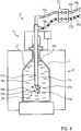
- FIG. 4 an alternative embodiment of the treatment station 5 is shown in a side view. This is different from the one before in the Figures 2 - 3 illustrated embodiment only in that the filling rod 21 designed as stretch rod 13 and the shut-off device 22 have separate paths for the liquid portion 24a and the particle-like portion 20b. All other features correspond to those in the Figures 2-3 illustrated treatment station. 5
- the shut-off device 22 after the valves, forwards the liquid product portion 24a from the line 23a or the particle-like portion 24b from the line 23b separately to the product lines 15a, 15b. These are correspondingly connected to the separately formed in the stretch rod 13 channels 21 b and 21 c. Consequently, the liquid product fraction flows 24 a via the product line 15 a in the centrally disposed channel 21 b and exits at the lower end of the stretch rod 13 through the opening 21 d in the plastic container 2.
- the particle-like product portion 24b passes through the product line 15b in the concentric with the channel 21 b formed channel 21 c and exits through the opening 21 e from the stretch rod 13 in the plastic container 2.
- the outer wall of the central channel 21b forms the inner wall of the annular channel 21c.
- the two walls of the annular channel 21c are spaced so far that the particulate product portions 24b are not crushed.
- the distance is 10 mm. This makes it possible to promote the different product portions 24a, 24b independently of each other into the plastic container 2 and thereby treat particularly gently.
- the central channel 21 b is provided for the particulate product portions 24b and the annular channel 21c for the liquid or pasty product portions.
- the liquid level 24c is already at the final filling level.
- the particle-like portion 24b is not pulled apart by the negative pressure during rapid filling of the liquid product portion 24a and the product can be filled particularly quickly, yet gently.
- Form filling machine 1 or treatment stations 5 are used as follows:
- the preform 3 is stretched with the stretch rod 13 of the valve head 11 in the mold 6 and then formed with the fluid nozzle 12 or the filling member 21 of the valve head 11 with a suitable molding fluid to the finished plastic container 2.
- the mold fluid is sucked off and then the container 2 filled with the liquid product portion 24a and the particulate product portion 24b in the mold 6.
- the plastic container 2 is formed with the liquid product portion 24a as a molding fluid and then only the particulate product portion 24b is added.
- the particle-like product portion 24b is conveyed through suitably dimensioned passages of the valve head 11 with the lowest possible pressurization and thus filled into the plastic container 2 in the best possible way.
Landscapes
- Engineering & Computer Science (AREA)
- Mechanical Engineering (AREA)
- Manufacturing & Machinery (AREA)
- Basic Packing Technique (AREA)
Abstract
Description
- Die Erfindung betrifft eine Formfüllmaschine und ein Formfüllverfahren mit den Merkmalen der Oberbegriffe von Anspruch 1 bzw. 10.
- Bekanntermaßen lassen sich Kunststoffbehälter im Streckblasverfahren aus Vorformlingen herstellen.
- Alternativ zu einem Aufblasen der Behälter mit Pressluft beschreibt die
EP 1529620 B1 ein Verfahren zum hydraulischen Umformen von Vorformlingen zu Kunststoffflaschen. Zu diesem Zweck werden die Vorformlinge zuerst erwärmt, in eine Hohlform verbracht und dort in Längsrichtung gereckt. Es wird ferner Mineralwasser oder dergleichen unter Überdruck eingeleitet, um die endgültige Behälterform herzustellen. Das Mineralwasser verbleibt im Behälter, sodass ein nachfolgender separater Abfüllschritt entbehrlich ist. - Die
US 2011/0031659 A1 beschreibt ferner ein Verfahren, bei dem ein erwärmter Vorformling mittels einer Reckstange gereckt und anschließend mittels eines inkompressiblen Fluids, insbesondere Wasser, hydraulisch zu einem Behälter geweitet wird. Danach wird das Fluid durch Pressluft verdrängt und läuft aus dem Behälter ab. - Nachteilig dabei ist, dass die Qualität von Produkten mit einem flüssigen oder pastösen Anteil und einem partikelartigen Anteil beeinträchtigt werden kann.
- Aufgabe der vorliegenden Erfindung ist es daher, eine Formfüllmaschine bereitzustellen, mit der eine Qualitätsminderung von derartigen Produkten beim Abfüllen in die Kunststoffbehälter vermieden wird.
- Diese Aufgabe wird bei einer Formfüllmaschine mit den Merkmalen des Oberbegriffs von Anspruch 1 mit den Merkmalen des kennzeichnenden Teils gelöst, gemäß dem der Ventilkopf zum Abfüllen eines Produkts mit einem flüssigen oder pastösen Anteil und mit einem partikelartigen Anteil, insbesondere Fruchtstücke, ausgebildet ist.
- Vorteilhafte Ausführungsformen der Erfindung sind in den Unteransprüchen definiert.
- Dadurch, dass der Ventilkopf sowohl zum Abfüllen des flüssigen oder pastösen als auch des partikelartigen Produktanteils ausgebildet ist, können mit der Formfüllmaschine auch partikelartige Produktanteile, wie Fruchtstücke, ohne Quetschung in den Kanälen des Ventilkopfs bzw. ohne Druckbeschädigung in die Kunststoffbehälter abgefüllt werden. Folglich wird eine Qualitätsminderung des Produkts beim Abfüllen vermieden.
- Die Formfüllmaschine kann in einer Getränkeverarbeitungsanlage angeordnet sein. Die Vorrichtung kann einem Vorratsbehälter für Vorformlinge, einem Rinser, einer Transporteinrichtung, einer Spritzgussmaschine zum Herstellen der Vorformlinge und/oder einem Ofen zum Erwärmen der Vorformlinge nachgeordnet sein. Die Vorrichtung kann einer Transporteinrichtung, einem Verschließer und/oder einer Verpackungsmaschine vorgeordnet sein.
- Der Kunststoffbehälter kann dafür vorgesehen sein, Getränke, Hygieneartikel, Pasten, chemische, biologische und/oder pharmazeutische Produkte aufzunehmen. Der Kunststoffbehälter kann eine Kunststoffflasche, eine Dose und/oder eine Tube sein. Bei dem Kunststoffbehälter kann es sich im Speziellen um einen PET-, HD-PE- oder PP-Behälter bzw. -Flasche handeln. Der Vorformling kann dazu vorgesehen sein, durch Umformung in der Hohlform in den Kunststoffbehälter expandiert zu werden.
- Flüssigkeiten, auch solche mit darin gelöstem Kohlendioxid oder dergleichen, sind definitionsgemäß hinsichtlich ihrer Funktion beim Ausformen und Füllen der Behälter inkompressible Fluide im Gegensatz zu Gasen, die funktional als kompressible Fluide definiert sind.
- Die Formfüllmaschine kann zum Transport von Kunststoffbehältern eine Transporteinrichtung umfassen. Die Transporteinrichtung kann ein Förderband oder Karussell sein. Das Karussell kann um eine vertikale Achse mittels eines Antriebs drehbar ausgebildet sein. "Vertikal" kann hier bedeuten, dass dies die Richtung ist, die auf den Erdmittelpunkt gerichtet ist. Die Transporteinrichtung kann Behälteraufnahmen zur Aufnahme der Kunststoffbehälter am Hals, am Behälterkörper und/oder Behälterboden umfassen. Ein Transportstern kann der Formfüllmaschine vorund/oder nachgeordnet sein.
- Die Formfüllmaschine kann wenigstens eine Behandlungsstation zum expandierenden Umformen des Vorformlings zum Kunststoffbehälter in der Hohlform und zum Abfüllen des Produkts in den Kunststoffbehälter in der Hohlform umfassen. Die Formfüllmaschine kann mehrere Behandlungsstationen umfassen, die insbesondere mit den Behälteraufnahmen der Transporteinrichtung korrespondieren. Dadurch können mit der Formfüllmaschine mehrere Kunststoffbehälter parallel hergestellt und befüllt werden. Jede Behandlungsstation kann eine Hohlform und einen Ventilkopf umfassen. Die Behandlungsstationen können mit einem Drehverteiler zur Verteilung des Formfluids, des Produkts, eines Gases, eines Unter- und/oder Überdrucks verbunden sein. Die Behandlungsstationen können derart ausgebildet sein, dass die Vorformlinge in die Hohlform eingebracht, mit der Reckstange gestreckt, mit einem Formfluid zum Kunststoffbehälter ausgeformt, das Formfluid wieder abgesaugt und das Produkt in den Kunststoffbehälter abgefüllt wird. Das Formfluid kann Wasser oder eine geeignete inkompressible Flüssigkeit zur Behälterumformung sein. Ebenso ist denkbar, dass die Behandlungsstationen derart ausgebildet sind, dass der Vorformling in die Hohlform eingebracht, mit der Reckstange gestreckt und mittels des Produkts oder mit dem flüssigen oder pastösen Anteil zum Kunststoffbehälter ausgeformt wird.
- Der Ventilkopf kann dazu ausgebildet sein, beim Ausformen und/oder beim Abfüllen des Produkts mit der Mündung des Vorformlings bzw. des Kunststoffbehälters zu korrespondieren. Ferner kann eine Verfahreinheit dazu vorgesehen sein, um nach dem Einbringen des Vorformlings die Hohlform mit dem Ventilkopf im Mündungsbereich zu verschließen. Ferner kann der Ventilkopf Ventile, Leitungen, Düsen, Weichen und dergleichen umfassen, um das Formfluid, ein Gas, das Produkt, den flüssigen oder pastösen Produktanteil, den partikelartigen Produktanteil und/oder weitere Produktanteile in den Vorformling und/oder den Kunststoffbehälter ein- oder auszuführen. Darüber hinaus kann der Ventilkopf zum Absaugen des Formfluids und/oder des Gases ausgebildet sein. Insbesondere kann der Ventilkopf dazu vorgesehen sein, einen Unter- und/oder Überdruck in den Vorformling bzw. den Kunststoffbehälter einzubringen. Ferner kann der Ventilkopf einen Kompressor umfassen oder mit diesem verbunden sein, um einen Druck auf das Formfluid und/oder das Gas aufzubringen. Der Kompressor kann beispielsweise ein Zylinder mit einem Kolben oder eine Pumpe umfassen. Darüber hinaus kann der Ventilkopf mit einer Vakuumpumpe verbunden sein. Die Ventile können dazu vorgesehen sein, den Fluss des Formfluids, des Produkts und/oder des Gases zu regulieren, freizugeben und/oder zu sperren.
- Die Reckstange kann dazu vorgesehen sein, den Vorformling in einem erwärmten Zustand in der Hohlform zu strecken. Das Füllorgan kann wenigstens teilweise in der Reckstange integriert sein. Die Reckstange kann mit einer Längsverstellung oder über eine Kurvensteuerung entlang der Längsachse des Vorformlings verfahrbar sein.
- Dass der Ventilkopf zum Abfüllen eines Produkts mit einem flüssigen oder pastösen Anteil und mit einem partikelartigen Anteil ausgebildet ist, kann hier bedeuten, dass die Kanäle für das Produkt oder wenigstens einen Anteil davon derart ausgelegt sind, dass der partikelartige Anteil beim Abfüllen nicht gequetscht wird.
- Der flüssige oder pastöse Produktanteil kann ein flüssiges Lebensmittel, wie beispielsweise Saft, Bier, Wein, Milch, Tee, Kaffee oder dergleichen umfassen. Ebenso kann der flüssige oder pastöse Anteil einen Hygieneartikel, wie beispielsweise Parfum, Flüssigseife, Shampoo, Duschgel oder dergleichen umfassen. Der partikelartige Produktanteil kann Fruchtstücke, Körner (beispielsweise Samenkörner in einem Müsli), Geleestücke und/oder Fruchtanteile in einer Marmelade umfassen. Bei einem Hygieneartikel kann der partikelartige Anteil Seifenpartikel umfassen, die zur optischen Produktaufwertung eine andere Farbe aufweisen, als der flüssige oder pastöse Anteil.
- Das Füllorgan kann derart ausgebildet sein, dass durch das Abfüllen des flüssigen oder pastösen Produktanteils ein Innendruck auf den Vorformling oder den mit der Reckstange gestreckten Vorformling derart aufbringbar ist, dass der Kunststoffbehälter in der Hohlform ausformbar ist. Dadurch kann der flüssige oder pastöse Produktanteil als Formfluid zum Ausformen des Kunststoffbehälters eingesetzt werden. Folglich muss das Formfluid nach dem Ausformen nicht mehr aus dem Kunststoffbehälter abgesaugt werden.
- Das Füllorgan kann derart ausgebildet sein, dass der partikelartige Produktanteil nach dem Ausformen des Kunststoffbehälters darin abfüllbar ist. Dadurch wird der partikelartige Produktanteil beim Abfüllen nicht mit einem Überdruck beaufschlagt und so besonders schonend behandelt. Denkbar ist hier, dass zunächst der Vorformling oder der mit der Reckstange gestreckte Vorformling mittels des flüssigen oder pastösen Produktanteils in der Hohlform zum Kunststoffbehälter ausgeformt wird und anschließend der partikelartige Produktanteil abgefüllt wird.
- Die Formfüllmaschine kann eine Absperreinrichtung zum wahlweisen Durchlassen oder Sperren wenigstens eines der Produktanteile umfassen, wobei die Absperreinrichtung insbesondere im Füllorgan und/oder in einer Produktzuführleitung des Füllorgans angeordnet ist. Dadurch ist es möglich, den partikelartigen Produktanteil zeitlich getrennt von dem flüssigen oder pastösen Produktanteil in den Kunststoffbehälter abzufüllen. Ebenso ist es möglich, durch die Absperreinrichtung den flüssigen oder pastösen Produktanteil zeitlich getrennt von einem Gemisch der beiden Produktanteile abzufüllen. Beispielsweise kann die Absperreinrichtung ein Rückhaltegitter oder -sieb umfassen, mit dem die partikelartigen Produktanteile im Füllorgan und/oder in der Produktzuführleitung rückhaltbar sind. Ebenso kann die Absperreinrichtung ein Ventil zum Freigegeben oder Sperren des flüssigen oder pastösen Produktanteils und/oder ein weiteres Ventil zum Freigeben oder Sperren des partikelartigen Produktanteils umfassen.
- In der Reckstange kann wenigstens ein Kanal zum Abfüllen wenigstens eines Produktanteils oder des Produkts ausgebildet sein. Dadurch kann die Reckstange besonders effizient sowohl zum Strecken des Vorformlings als auch zum Abfüllen des wenigstens einen Produktanteils oder des Produkts eingesetzt werden. Ferner kann die Reckstange entlang der Längsachse des Kunststoffbehälters verstellbar ausgebildet sein, um den Vorformling zu strecken und/oder dem sich verändernden Flüssigkeitsspiegel beim Abfüllen des Produkts anzupassen.
- Das Füllorgan kann mehrere separate Kanäle für unterschiedliche Produktanteile umfassen, insbesondere einen ersten Kanal für den flüssigen oder pastösen Produktanteil und einen zweiten Kanal für den partikelartigen Produktanteil. Dadurch können die Produktanteile voneinander getrennt gehalten werden, bis sie an den Kunststoffbehälter abgegeben werden. Folglich ist eine besonders genaue Dosierung der einzelnen Anteile möglich.
- Wenigstens einer der separaten Kanäle kann in der Reckstange ausgebildet sein. Dadurch kann die Reckstange besonders effizient als Füllorgan eingesetzt werden und der entsprechende Produktanteil kann an der gewünschten Höhe in den Kunststoffbehälter abgegeben werden. An der Reckstange kann für jeden der separaten Kanäle wenigstens eine Austrittsöffnung zur Abgabe der Produktanteile in den Kunststoffbehälter ausgebildet sein. Ebenso ist denkbar, dass mehrere der separaten Kanäle in eine Austrittsöffnung an der Reckstange münden.
- Die separaten Kanäle können um eine gemeinsame Achse konzentrisch ausgebildet sein und jeweils unterschiedliche Durchmesser aufweisen. Dadurch ist das Füllorgan besonders einfach aufgebaut. Beispielsweise können dadurch die flüssigen oder pastösen Produktanteile durch ein zentrales Rohr und die partikelartigen Produktanteile durch einen das zentrale Rohr umgebenden Ringkanal geführt werden. Eine umgekehrte Nutzung der Kanäle für die jeweiligen Anteile ist ebenfalls denkbar.
- Wenigstens einer der separaten Kanäle kann für den partikelartigen Produktanteil ausgebildet sein, insbesondere mit einem Durchmesser in einem Bereich von 5 mm bis 20 mm, weiterhin insbesondere in einem Bereich von 8-12 mm. Vorzugsweise kann der Durchmesser größer sein als die maximale Größe der Partikel des partikelartigen Produktanteils. Dadurch wird eine Qualitätsbeeinträchtigung des partikelartigen Produktanteils durch ein Verklemmen im Kanal vermieden.
- Darüber hinaus stellt Erfindung mit dem Anspruch 10 ein Formfüllverfahren für Kunststoffbehälter bereit, wobei ein Vorformling mit einer Reckstange eines Ventilkopfs in einer Hohlform gestreckt und mit einem Füllorgan des Ventilkopfs in der Hohlform befüllt und dabei zum Kunststoffbehälter ausgeformt wird, dadurch gekennzeichnet, dass mit dem Füllorgan ein flüssiger oder pastöser Produktanteil und ein partikelartiger Produktanteil, insbesondere Fruchtstücke, abgefüllt werden.
- Dadurch, dass mit dem Füllorgan sowohl der flüssige oder pastöse Produktanteil als auch der partikelartige Produktanteil abgefüllt werden, werden die partikelartigen Produktanteile besonders schonend behandelt. Durch die Auslegung des Ventilkopfs werden eine Quetschung und eine Druckbeaufschlagung des partikelartigen Produktanteils, beispielsweise auf Fruchtstücke und eine daraus folgende Qualitätsminderung des Produkts vermieden.
- Bei dem Formfüllverfahren kann der flüssige oder pastöse Produktanteil und der partikelartige Produktanteil jeweils durch separate Kanäle des Füllorgans abgefüllt werden, wobei wenigstens einer der Kanäle in der Reckstange ausgebildet ist. Dadurch kann der partikelartige Produktanteil besonders schonend und genau dosiert dem Kunststoffbehälter zugeführt werden. Darüber hinaus ist es auch möglich, die separaten Kanäle so auszulegen, dass der jeweilige Produktanteil besonders schonend gleichzeitig schnell abgefüllt wird.
- Der flüssige oder pastöse Produktanteil und der partikelartige Produktanteil können mittels einer Absperreinrichtung wenigstens zeitweise nacheinander in den Kunststoffbehälter abgefüllt werden. Dadurch können die Produktanteile unabhängig voneinander dem Kunststoffbehälter zugeführt werden.
- Der Vorformling oder der gestreckte Vorformling kann mit dem flüssigen oder pastösen Produktanteil zum Kunststoffbehälter umgeformt und anschließend kann der partikelartige Produktanteil in den Kunststoffbehälter abgefüllt werden. Dadurch wird der partikelartige Produktanteil nicht durch den Druck beim Ausformen des Kunststoffbehälters belastet. Folglich werden also empfindliche Produktanteile, wie beispielsweise Fruchtstücke, nicht durch einen äußeren Druck belastet und dadurch in der Qualität vermindert.
- Darüber hinaus kann das Formfüllverfahren nach einem der Ansprüche 10-13 mit einer Formfüllmaschine nach einem der Ansprüche 1-9 durchgeführt werden. Ferner kann das Formfüllverfahren die zuvor in Bezug auf die Formfüllmaschine beschriebenen Merkmale einzelnen oder in beliebigen Kombinationen umfassen.
- Weitere Merkmale und Vorteile der Erfindung werden nachfolgend anhand der in den Figuren dargestellten Ausführungsbeispiele näher erläutert. Dabei zeigt:
- Figur 1
- ein Ausführungsbeispiel einer Formfüllmaschine mit mehreren Behandlungsstationen und einen vorgeordneten Ofen zur Erwärmung der Vorformling in einer Draufsicht;
- Figur 2
- eine Behandlungsstation der in der
Figur 1 dargestellten Formfüllmaschine in einer seitlichen Schnittansicht; - Figur 3
- die in der
Figur 2 dargestellte Behandlungsstation beim Abfüllen eines Produkts mit flüssigen und partikelartigen Anteilen in einer seitlichen Ansicht; und - Figur 4
- eine alternative Ausführungsform der in der
Figur 3 dargestellten Behandlungsstation in einer seitlichen Ansicht, bei der das Füllorgan separate Kanäle für die jeweiligen Produktanteile aufweist. - In der
Figur 1 ist ein Ausführungsbeispiel einer Formfüllmaschine 1 mit einem vorgeschalteten Ofen 7 in einer Draufsicht dargestellt. Zu sehen sind die Vorformlinge 3, die zunächst den Ofen 7 durchlaufen und dadurch soweit erwärmt werden, dass sie mit der nachfolgenden Formfüllmaschine 1 in die gewünschte Behälterform umgeformt werden können. Anschließend werden die erwärmten Vorformlinge mit dem Einlaufstern 8 an die Behandlungsstationen 5 übergeben, die nachfolgend genauer anhand derFiguren 2 beschrieben werden. Beim Umlauf des Karussells 4 entlang der Richtung 4a werden die Vorformlinge 3 in den Behandlungsstationen 5 gestreckt, in die gewünschte Behälterform umgeformt und mit dem Produkt befüllt. Dabei verbleiben die Vorformlinge 3 bzw. die ausgeformten Behälter 2 immer in den Hohlformen 6. Nach dem Befüllen werden die Behälter 2 über den Auslaufstern 9 weiteren Behandlungsschritten zugeführt. Beispielsweise kann der Formfüllmaschine 1 ein Verschließer nach- oder zugeordnet sein, mit dem die Kunststoffbehälter 2 verschlossen werden. Die Kunststoffbehälter 2 sind hier PET-Behälter, können jedoch aus jedem anderen geeigneten Kunststoff sein. - In der
Figur 2 ist eine Behandlungsstation 5 der in derFigur 1 dargestellten Formfüllmaschine 1 in einer seitlichen Schnittansicht gezeigt. Zu sehen ist, dass der Vorformling 3 bereits in die Hohlform 6 eingebracht ist. Im Bereich der Mündung weist der Vorformling 3 einen Kragen und ein hier nicht genauer dargestelltes Gewinde auf, das später zum Aufschrauben eines Verschlusses dient. Die einzelnen Formteile 6a-6c der Hohlform 6 sind über den mehrteiligen Formträger 10 in die Richtungen Ra, Rb, Rc verfahrbar, um den fertig ausgeformten Behälter nach dem Befüllen freizugeben. Denkbar ist auch, dass der Vorformling 3 entweder von oben in die Öffnung der Hohlform 6 gesteckt oder durch ein Öffnen und Schließen der Formteile 6a-6c in die Hohlform 6 eingebracht wird. - Zu sehen ist ferner der Ventilkopf 11 mit der Reckstange 13, die hier zusätzlich zur Streckfunktion als Füllorgan 21 ausgebildet ist. Ferner ist der Ventilkopf 11 mittels einer hier nicht dargestellten Verfahreinheit oder Kurvensteuerung in der Richtung 11a verfahrbar, um ihn auf die Hohlform 6 abzusenken und diese damit gegenüber der Umgebung beim Umformen und Befüllen abzuschließen. Denkbar ist, dass der Ventilkopf 11 Dichtungselemente zum Vorformling 3 und/oder zur Hohlform 6 aufweist.
- Im Ventilkopf 11 ist die Reckstange 13 über eine hier ebenfalls nicht dargestellte Verfahreinheit oder Kurvensteuerung entlang der Richtung 13a verfahrbar, so dass der erwärmte Vorformling 3 in üblicher Weise gestreckt werden kann.
- Ferner ist am Ventilkopf 11 die Fluiddüse 12 ausgebildet, mittels der ein Formfluid in den gestreckten Vorformling 3 eingepresst werden kann. Das Formfluid ist hier Wasser oder eine zur Umformung geeignete Flüssigkeit und wird über die Zuleitung 14 und den Kompressor 20 mit einem geeigneten Druck bereitgestellt. Dieser ist beispielsweise als Druckzylinder ausgeführt. Durch das Formfluid wird der gestreckte Vorformling 3 besonders schnell an die formgebenden Innenflächen der Hohlform 6 gepresst und so zum fertigen Kunststoffbehälter ausgeformt. Dabei nimmt das Formfluid gleichzeitig die Wärme des Vorformlings 3 auf, so dass der Behälter nach dem Umformen möglichst rasch seine Formstabilität erhält.
- Nach dem Ausformen des Kunststoffbehälters wird das Formfluid über die Öffnungen 13b und einen Kanal in der Reckstange 13 in die hydraulische Absaugleitung 16 abgesaugt.
- Beim Abfüllen wird das Produkt über die Produktzuleitung 15 und einen Kanal im Füllorgan 21 bzw. in der Reckstange 13 in den ausgeformten Kunststoffbehälter abgefüllt. Hierzu befindet sich am Füllorgan 21 bzw. an der Reckstange 13 eine entsprechende Abgabeöffnung. Beim Befüllen wird der Kunststoffbehälter über die pneumatischen Absaugleitungen 17, 18 am Ventilkopf 11 bzw. an der Hohlform 6 in einem Druckgleichgewicht zwischen der Innen- und Außenseite gehalten, so dass der Kunststoffbehälter nicht kollabiert. Vorteilhaft ist dabei eine Befüllung unter Unterdruck im Kunststoffbehälter.
- Alternativ dazu ist denkbar, dass die Behandlungsstation 5 derart ausgebildet ist, dass das Produkt oder der flüssige oder pastöse Produktanteil als Formfluid zum Ausformen des Kunststoffbehälters eingesetzt wird. Dadurch muss das Formfluid dann nicht aus dem fertig ausgeformten Kunststoffbehälter wieder abgesaugt und durch das Produkt ersetzt werden.
- Ferner ist der Medienverteiler 19 zu sehen, über den alle Behandlungsstationen 5 der Formfüllmaschine 1 mit dem Formfluid, dem Produkt und einem Unterdruck versorgt werden.
- Der Ventilkopf 11 ist, wie nachfolgend genauer anhand der
Figuren 3 und4 beschrieben wird, besonders für ein Produkt mit einem flüssigen oder pastösen Anteil und einen partikelartigen Anteil ausgebildet. - In der
Figur 3 ist die zuvor in derFigur 2 dargestellte Behandlungsstation 5 beim Abfüllen des Produkts 24 in einer seitlichen Ansicht gezeigt. Zu sehen ist, dass die Hohlform 6 noch zusammengefahren ist und darin der fertig ausgeformte Kunststoffbehälter 2 mit der als Füllorgan 21 ausgebildeten Reckstange 13 befüllt wird. - Damit die einzelnen Produktanteile 24a, 24b in der gewünschten Abfolge und/oder Menge an die Reckstange 13 zugeführt werden, ist in der Produktzuleitung 15 die Absperreinrichtung 22 vorgesehen. Durch entsprechende Ventile der Absperreinrichtung 22 ist wahlweise der flüssige Produktanteil 24a aus der Leitung 23a oder der partikelartige Produktanteil 24b aus der Leitung 23b oder eine beliebige Mischung daraus zuführbar. Weiterhin ist in der Reckstange der Kanal 21a ausgebildet, mit der die Produktanteile 24a, 24b durch die Öffnung 21 d in das Innere des Kunststoffbehälters 2 abgegeben werden. Dadurch ist es möglich, den flüssigen Anteil 24a, den partikelartigen Anteil 24b oder eine Mischung daraus in der gewünschten zeitlichen Abfolge in den Kunststoffbehälter 2 abzufüllen. Es ist denkbar, dass die Reckstange 13 beim Abfüllen entlang der Längsachse des Kunststoffbehälters 2 verfahren wird. Dadurch kann das Herausspritzen des flüssigen Anteils durch ein Hineinfallen des partikelartigen Anteils vermieden werden. Ebenso ist denkbar, dass die Reckstange 13 ein Rückgasrohr aufweist, durch das Gas oder Luft beim Füllen entweichen kann.
- Alternativ ist mit der in
Figur 3 dargestellten Behandlungsstation 5 denkbar, den Kunststoffbehälter 2 mit dem flüssigen Produktanteil 24a auszuformen und erst danach die partikelartigen Produktanteile 24b abzufüllen. Dadurch werden beispielsweise Fruchtstücke nicht mit Druck zum Ausformen beaufschlagt und dadurch schonend abgefüllt. - Der Kanal 21a in der Reckstange 13 ist hier im Durchmesser größer ausgebildet als die partikelartigen Produktanteile 24b. Dadurch werden diese bei der Förderung durch die Reckstange 13 nicht gequetscht. Beispielsweise beträgt der Durchmesser des Kanals 21 a 10 mm.
- In der
Figur 4 ist eine alternative Ausführung der Behandlungsstation 5 in einer seitlichen Ansicht dargestellt. Diese unterscheidet sich von der zuvor in denFiguren 2 - 3 dargestellten Ausführungsform lediglich dadurch, dass die als Füllorgan 21 ausgebildete Reckstange 13 und die Absperreinrichtung 22 getrennte Wege für den flüssigen Anteil 24a und den partikelartigen Anteil 20b aufweisen. Alle weiteren Merkmale entsprechen der in denFiguren 2-3 dargestellten Behandlungsstation 5. - Zu sehen ist, dass die Absperreinrichtung 22 nach den Ventilen den flüssigen Produktanteil 24a aus der Leitung 23a bzw. den partikelartigen Anteil 24b aus der Leitung 23b getrennt an die Produktleitungen 15a, 15b weiterleitet. Diese sind entsprechend mit den in der Reckstange 13 separat ausgebildeten Kanälen 21b und 21 c verbunden. Folglich fließt der flüssige Produktanteil 24a über die Produktleitung 15a in den zentral angeordneten Kanal 21 b und tritt am unteren Ende der Reckstange 13 durch die Öffnung 21 d in den Kunststoffbehälter 2 aus. Der partikelartige Produktanteil 24b gelangt dagegen durch die Produktleitung 15b in den konzentrisch zum Kanal 21 b ausgebildeten Kanal 21 c und tritt durch die Öffnung 21 e aus der Reckstange 13 in den Kunststoffbehälter 2 aus. Anders ausgedrückt bildet die Außenwand des zentralen Kanals 21b die Innenwand des Ringkanals 21c. Die beiden Wände des Ringkanals 21c sind dabei soweit beabstandet, dass die partikelartigen Produktanteile 24b nicht gequetscht werden. Beispielsweise ist der Abstand 10 mm. Dadurch ist es möglich, die verschiedenen Produktanteile 24a, 24b unabhängig voneinander bis in den Kunststoffbehälter 2 zu fördern und dadurch besonders schonend zu behandeln. Alternativ ist auch denkbar, dass der zentrale Kanal 21 b für die partikelartigen Produktanteile 24b und der Ringkanal 21c für die flüssigen oder pastösen Produktanteile vorgesehen ist.
- Ferner ist zu sehen, dass beim Befüllen der partikelartigen Produktanteile 24b der Flüssigkeitsspiegel 24c bereits auf der endgültigen Abfüllhöhe liegt. Dadurch wird der partikelartige Anteil 24b nicht durch den Unterdruck beim schnellen Abfüllen des flüssigen Produktanteils 24a auseinandergezogen und das Produkt kann besonders schnell und trotzdem schonend abgefüllt werden.
- Die zuvor in den
Figuren 1-4 dargestellte Formfüllmaschine 1 bzw. die Behandlungsstationen 5 werden wie folgt eingesetzt: - Zunächst wird der Vorformling 3 mit der Reckstange 13 des Ventilkopfs 11 in der Hohlform 6 gestreckt und dann mit der Fluiddüse 12 oder dem Füllorgan 21 des Ventilkopfs 11 mit einem geeigneten Formfluid zum fertigen Kunststoffbehälter 2 ausgeformt. Zunächst wird das Formfluid abgesaugt und danach der Behälter 2 mit dem flüssigen Produktanteil 24a und dem partikelartigen Produktanteil 24b in der Hohlform 6 befüllt. Alternativ ist denkbar, dass der Kunststoffbehälter 2 mit dem flüssigen Produktanteil 24a als Formfluid ausgeformt und dann nur noch der partikelartige Produktanteil 24b zugegeben wird.
- Mit der Formfüllmaschine 1 und dem beschriebenen Formfüllverfahren wird der partikelartige Produktanteil 24b durch geeignet dimensionierte Kanälen des Ventilkopfs 11 mit möglichst geringer Druckbeaufschlagung gefördert und damit möglichst qualitätsschonend in den Kunststoffbehälter 2 abgefüllt.
- Es versteht sich, dass in den zuvor beschriebenen Ausführungsbeispielen genannte Merkmale nicht auf diese speziellen Kombinationen beschränkt und in beliebigen anderen Kombinationen möglich sind.
Claims (13)
- Formfüllmaschine (1) zum Ausformen eines Kunststoffbehälters (2) aus einem Vorformling (3) in einer Hohlform (6) und zur Produktbefüllung des Kunststoffbehälters (2) in der Hohlform (6),
mit einem Ventilkopf (11), der eine Reckstange (13) zum Strecken des Vorformlings (3) und ein Füllorgan (21) zum Abfüllen eines Produkts (24) in den Kunststoffbehälter (2) in der Hohlform (6) umfasst,
dadurch gekennzeichnet, dass
der Ventilkopf (11) zum Abfüllen eines Produkts (24) mit einem flüssigen oder pastösen Anteil (24a) und mit einem partikelartigen Anteil (24b), insbesondere Fruchtstücke, ausgebildet ist. - Formfüllmaschine (1) nach Anspruch 1, wobei das Füllorgan (21) derart ausgebildet ist, dass durch das Abfüllen des flüssigen oder pastösen Produktanteils (24a) ein Innendruck auf den Vorformling (3) oder den mit der Reckstange (13) gestreckten Vorformling (3) derart aufbringbar ist, dass der Kunststoffbehälter (2) in der Hohlform (6) ausformbar ist.
- Formfüllmaschine (1) nach Anspruch 1 oder 2, wobei das Füllorgan (21) derart ausgebildet ist, dass der partikelartige Produktanteil (24b) nach dem Ausformen des Kunststoffbehälters (2) darin abfüllbar ist.
- Formfüllmaschine (1) nach einem der vorangegangenen Ansprüche, wobei die Formfüllmaschine (1) eine Absperreinrichtung (22) zum wahlweisen Durchlassen oder Sperren wenigstens eines der Produktanteile (24a, 24b) umfasst, wobei die Absperreinrichtung (22) insbesondere im Füllorgan (21) und/oder in einer Produktzuführleitung (15) des Füllorgans (21) angeordnet ist.
- Formfüllmaschine (1) nach einem der vorangegangenen Ansprüche, wobei wenigstens ein Kanal (21a -21c) zum Abfüllen wenigstens eines Produktanteils (24a, 24b) oder des Produkts (24) in der Reckstange (13) ausgebildet ist.
- Formfüllmaschine (1) nach einem der vorangegangenen Ansprüche, wobei das Füllorgan (21) mehrere separate Kanäle (21a -21c) für unterschiedliche Produktanteile (24a, 24b) umfasst, insbesondere einen ersten Kanal (21 b) für den flüssigen oder pastösen Produktanteil (24a) und einen zweiten Kanal (21 c) für den partikelartigen Produktanteil (24b).
- Formfüllmaschine (1) nach Anspruch 6, wobei wenigstens einer der separaten Kanäle (21a -21c) in der Reckstange (13) ausgebildet ist.
- Formfüllmaschine (1) nach Anspruch 6 oder 7, wobei die separaten Kanäle (21a - 21 c) um eine gemeinsame Achse konzentrisch ausgebildet sind und jeweils unterschiedliche Durchmesser aufweisen.
- Formfüllmaschine (1) nach einem der Ansprüche 6 - 8, wobei wenigstens einer der separaten Kanäle (21 a, 21c) für die partikelartigen Produktanteile (24b) ausgebildet ist, insbesondere mit einem Durchmesser in einem Bereich von 5 mm bis 20 mm, weiterhin insbesondere in einem Bereich von 8 - 12 mm.
- Formfüllverfahren für Kunststoffbehälter (2),
wobei ein Vorformling (3) mit einer Reckstange (13) eines Ventilkopfs (11) in einer Hohlform (6) gestreckt und
mit einem Füllorgan (21) des Ventilkopfs (11) in der Hohlform (6) befüllt und dabei zum Kunststoffbehälter (2) ausgeformt wird,
dadurch gekennzeichnet, dass
mit dem Füllorgan (21) ein flüssiger oder pastöser Produktanteil (24a) und ein partikelartiger Produktanteil (24b), insbesondere Fruchtstücke, abgefüllt werden. - Formfüllverfahren nach Anspruch 10, wobei der flüssige oder pastöse Produktanteil (24a) und der partikelartige Produktanteil (24b) jeweils durch separate Kanäle (21a -21c) des Füllorgans (21) abgefüllt werden, wobei wenigstens einer der Kanäle (21a -21c) in der Reckstange (13) ausgebildet ist.
- Formfüllverfahren nach Anspruch 10 oder 11, wobei der flüssige oder pastöse Produktanteil (24a) und der partikelartige Produktanteil (24b) mittels einer Absperreinrichtung (22) wenigstens zweitweise nacheinander in den Kunststoffbehälter (2) abgefüllt werden.
- Formfüllverfahren nach einem der Ansprüche 10 - 12, wobei der Vorformling (3) oder der gestreckte Vorformling mit dem flüssigen oder pastösen Produktanteil (24a) zum Kunststoffbehälter (2) umgeformt und anschließend der partikelartige Produktanteil (24b) in den Kunststoffbehälter (2) abgefüllt wird.
Priority Applications (1)
| Application Number | Priority Date | Filing Date | Title |
|---|---|---|---|
| EP14181662.9A EP2987612A1 (de) | 2014-08-20 | 2014-08-20 | Formfüllmaschine und Formfüllverfahren für einen Kunststoffbehälter |
Applications Claiming Priority (1)
| Application Number | Priority Date | Filing Date | Title |
|---|---|---|---|
| EP14181662.9A EP2987612A1 (de) | 2014-08-20 | 2014-08-20 | Formfüllmaschine und Formfüllverfahren für einen Kunststoffbehälter |
Publications (1)
| Publication Number | Publication Date |
|---|---|
| EP2987612A1 true EP2987612A1 (de) | 2016-02-24 |
Family
ID=51389991
Family Applications (1)
| Application Number | Title | Priority Date | Filing Date |
|---|---|---|---|
| EP14181662.9A Withdrawn EP2987612A1 (de) | 2014-08-20 | 2014-08-20 | Formfüllmaschine und Formfüllverfahren für einen Kunststoffbehälter |
Country Status (1)
| Country | Link |
|---|---|
| EP (1) | EP2987612A1 (de) |
Cited By (4)
| Publication number | Priority date | Publication date | Assignee | Title |
|---|---|---|---|---|
| WO2019147222A1 (en) | 2018-01-24 | 2019-08-01 | Amcor Rigid Plastics Usa, Llc | Foaming and fill level control through stretch rod |
| EP3616880A4 (de) * | 2017-04-27 | 2021-01-13 | Yoshino Kogyosho Co., Ltd. | Verfahren zur herstellung eines flüssigkeitsgefüllten behälters |
| EP3733375A4 (de) * | 2017-12-28 | 2021-09-29 | Yoshino Kogyosho Co., Ltd. | Verfahren zur herstellung eines flüssigkeitsgefüllten behälters |
| EP3978221A3 (de) * | 2020-10-05 | 2022-06-15 | Krones AG | Vorrichtung und verfahren zum umformen von kunststoffvorformlingen zu kunststoffbehältnissen mit verbesserter spülstangenanordnung |
Citations (7)
| Publication number | Priority date | Publication date | Assignee | Title |
|---|---|---|---|---|
| FR1491316A (fr) * | 1965-05-18 | 1967-08-11 | Stelle & Cowlishav Ltd | Perfectionnements aux machines effectuant la mise en forme et le remplissage de bouteilles en matière plastique |
| EP1348340A1 (de) * | 2002-03-28 | 2003-10-01 | Societe Des Produits Nestle S.A. | Milchprodukt mit Streifen oder einer Ummantelung |
| WO2007120807A2 (en) * | 2006-04-13 | 2007-10-25 | Amcor Limited | Liquid or hydraulic blow molding |
| EP1529620B1 (de) | 2003-11-06 | 2009-02-25 | Nestlé Waters Management & Technology | Herstellungsverfahren von Behältern aus Polyesterharz |
| US20110031659A1 (en) | 2005-03-15 | 2011-02-10 | Graeme Warner | Stretch Blow Moulding Method and Apparatus |
| WO2014019691A2 (de) * | 2012-08-01 | 2014-02-06 | Khs Gmbh | Verfahren sowie vorrichtung zum herstellen von einem flüssigen füllgut gefüllten behältern |
| EP2823948A1 (de) * | 2013-07-12 | 2015-01-14 | Discma AG | Station zur Formung eines Behälters in einer Einspritzkonfiguration und in einer Verdrängungskonfiguration |
-
2014
- 2014-08-20 EP EP14181662.9A patent/EP2987612A1/de not_active Withdrawn
Patent Citations (7)
| Publication number | Priority date | Publication date | Assignee | Title |
|---|---|---|---|---|
| FR1491316A (fr) * | 1965-05-18 | 1967-08-11 | Stelle & Cowlishav Ltd | Perfectionnements aux machines effectuant la mise en forme et le remplissage de bouteilles en matière plastique |
| EP1348340A1 (de) * | 2002-03-28 | 2003-10-01 | Societe Des Produits Nestle S.A. | Milchprodukt mit Streifen oder einer Ummantelung |
| EP1529620B1 (de) | 2003-11-06 | 2009-02-25 | Nestlé Waters Management & Technology | Herstellungsverfahren von Behältern aus Polyesterharz |
| US20110031659A1 (en) | 2005-03-15 | 2011-02-10 | Graeme Warner | Stretch Blow Moulding Method and Apparatus |
| WO2007120807A2 (en) * | 2006-04-13 | 2007-10-25 | Amcor Limited | Liquid or hydraulic blow molding |
| WO2014019691A2 (de) * | 2012-08-01 | 2014-02-06 | Khs Gmbh | Verfahren sowie vorrichtung zum herstellen von einem flüssigen füllgut gefüllten behältern |
| EP2823948A1 (de) * | 2013-07-12 | 2015-01-14 | Discma AG | Station zur Formung eines Behälters in einer Einspritzkonfiguration und in einer Verdrängungskonfiguration |
Cited By (9)
| Publication number | Priority date | Publication date | Assignee | Title |
|---|---|---|---|---|
| EP3616880A4 (de) * | 2017-04-27 | 2021-01-13 | Yoshino Kogyosho Co., Ltd. | Verfahren zur herstellung eines flüssigkeitsgefüllten behälters |
| US11504897B2 (en) | 2017-04-27 | 2022-11-22 | Yoshino Kogyosho Co., Ltd. | Liquid container manufacturing method |
| EP3733375A4 (de) * | 2017-12-28 | 2021-09-29 | Yoshino Kogyosho Co., Ltd. | Verfahren zur herstellung eines flüssigkeitsgefüllten behälters |
| US11511475B2 (en) | 2017-12-28 | 2022-11-29 | Yoshino Kogyosho Co., Ltd. | Method of manufacturing liquid container |
| WO2019147222A1 (en) | 2018-01-24 | 2019-08-01 | Amcor Rigid Plastics Usa, Llc | Foaming and fill level control through stretch rod |
| EP3743259A4 (de) * | 2018-01-24 | 2021-08-18 | Amcor Rigid Packaging USA, LLC | Schaum- und füllstandskontrolle durch streckstange |
| US11267183B2 (en) | 2018-01-24 | 2022-03-08 | Amcor Rigid Packaging Usa, Llc | Foaming and fill level control through stretch rod |
| EP3978221A3 (de) * | 2020-10-05 | 2022-06-15 | Krones AG | Vorrichtung und verfahren zum umformen von kunststoffvorformlingen zu kunststoffbehältnissen mit verbesserter spülstangenanordnung |
| US11607834B2 (en) | 2020-10-05 | 2023-03-21 | Krones Ag | Apparatus and method for forming plastic preforms into plastic containers with improved rinsing rod arrangement |
Similar Documents
| Publication | Publication Date | Title |
|---|---|---|
| EP2930138B1 (de) | Vorrichtung und verfahren zur herstellung einer kunststoffflasche und deren befüllung mit einem füllprodukt | |
| EP2319678B1 (de) | Vorrichtung und Verfahren zum Umformen von Kunststoffvorformlingen mit Sterilraum | |
| DE102011102090B4 (de) | Verfahren zum Reinigen und/oder Desinfizieren einer Vorrichtung zur Herstellung von mit einem flüssigen Füllgut gefüllten Behältern sowie Vorrichtung | |
| DE102014216562A1 (de) | Formfüllmaschine und Verfahren zum Ausformen und Füllen von Behältern | |
| EP2850029B1 (de) | Behältnisherstellungsanlage mit bodenkühlung der behältnisse | |
| DE19938724A1 (de) | Vorrichtung zur Herstellung von Kunststoffbehältern mittels Streckblasformen | |
| WO2012104019A1 (de) | Verfahren sowie vorrichtung zum herstellen von mit einem flüssigen füllgut gefüllten behältern | |
| EP2987612A1 (de) | Formfüllmaschine und Formfüllverfahren für einen Kunststoffbehälter | |
| EP2522485B1 (de) | Aseptische Blasformmaschine sowie -verfahren und Blasform mit steriler Luftabführung | |
| DE102019135257A1 (de) | Vorrichtung zum Befüllen eines Behälters mit einem Füllprodukt | |
| EP2709820A1 (de) | Verfahren sowie vorrichtung zum herstellen von gefüllten behältern aus vorformlingen | |
| EP2987606B1 (de) | Verfahren zum Ausformen und Füllen von Behältern und Formfüllmaschine | |
| EP3833628B1 (de) | Verfahren und vorrichtung zum befüllen von behältern mit einem co2-haltigen flüssigkeitsprodukt | |
| EP2730390B1 (de) | Verfahren zur gewährleistung der masshaltigkeit einer ausgiessöffnung in bzw. an einem in einem extrusionsblasverfahren hergestellten kunststoffbehälter | |
| EP2008667A1 (de) | Vorrichtung zum Behandeln von Gefäßen in einem Gefäßdesinfektionssystem | |
| EP3784469B1 (de) | Sterilisierbare blasluftwege und reckstange einer blasmaschine | |
| EP2987610B1 (de) | Formfüllmaschine zum Herstellen und Füllen von Kunststoffbehältern mit CO2-Recycling | |
| EP2314538B1 (de) | Vorrichtung und Verfahren zum verlustfreien Abfüllen von kontinuierlich gemischten Medien in Behältnisse | |
| EP2987609A1 (de) | Formfüllmaschine mit Reinigung und Verfahren | |
| DE1704022C3 (de) | Verfahren und Vorrichtung zum Herstellen und anschließenden Füllen und Verschließen von flaschenförmigen Hohlkörpern aus Kunststoff | |
| EP2949585B1 (de) | Verfahren und vorrichtung zum befüllen von flaschen | |
| DE102012105999A1 (de) | Blasmaschine und verfahren zum herstellen eines hohlkörpers aus einem vorformling mit einer blasmaschine | |
| EP2987617B1 (de) | Ventilblock für eine Behandlungsstation einer Formfüllmaschine und Formfüllmaschine mit einem solchen Ventilblock | |
| EP3012087B1 (de) | Hohlkörperherstellungsmaschine | |
| WO2020015871A1 (de) | Formfüllmaschine und formfüllverfahren für einen kunststoffbehälter |
Legal Events
| Date | Code | Title | Description |
|---|---|---|---|
| PUAI | Public reference made under article 153(3) epc to a published international application that has entered the european phase |
Free format text: ORIGINAL CODE: 0009012 |
|
| AK | Designated contracting states |
Kind code of ref document: A1 Designated state(s): AL AT BE BG CH CY CZ DE DK EE ES FI FR GB GR HR HU IE IS IT LI LT LU LV MC MK MT NL NO PL PT RO RS SE SI SK SM TR |
|
| AX | Request for extension of the european patent |
Extension state: BA ME |
|
| 17P | Request for examination filed |
Effective date: 20160819 |
|
| RBV | Designated contracting states (corrected) |
Designated state(s): AL AT BE BG CH CY CZ DE DK EE ES FI FR GB GR HR HU IE IS IT LI LT LU LV MC MK MT NL NO PL PT RO RS SE SI SK SM TR |
|
| GRAP | Despatch of communication of intention to grant a patent |
Free format text: ORIGINAL CODE: EPIDOSNIGR1 |
|
| INTG | Intention to grant announced |
Effective date: 20170914 |
|
| STAA | Information on the status of an ep patent application or granted ep patent |
Free format text: STATUS: THE APPLICATION IS DEEMED TO BE WITHDRAWN |
|
| 18D | Application deemed to be withdrawn |
Effective date: 20180125 |