EP3978155A1 - Raw material discharge device, method of processing of electronic/electrical device component scrap, and method of raw material discharge for electronic/electrical device component scrap - Google Patents
Raw material discharge device, method of processing of electronic/electrical device component scrap, and method of raw material discharge for electronic/electrical device component scrap Download PDFInfo
- Publication number
- EP3978155A1 EP3978155A1 EP20819496.9A EP20819496A EP3978155A1 EP 3978155 A1 EP3978155 A1 EP 3978155A1 EP 20819496 A EP20819496 A EP 20819496A EP 3978155 A1 EP3978155 A1 EP 3978155A1
- Authority
- EP
- European Patent Office
- Prior art keywords
- raw material
- storage unit
- discharge
- unit
- electronic
- Prior art date
- Legal status (The legal status is an assumption and is not a legal conclusion. Google has not performed a legal analysis and makes no representation as to the accuracy of the status listed.)
- Withdrawn
Links
Images




Classifications
-
- B—PERFORMING OPERATIONS; TRANSPORTING
- B65—CONVEYING; PACKING; STORING; HANDLING THIN OR FILAMENTARY MATERIAL
- B65G—TRANSPORT OR STORAGE DEVICES, e.g. CONVEYORS FOR LOADING OR TIPPING, SHOP CONVEYOR SYSTEMS OR PNEUMATIC TUBE CONVEYORS
- B65G65/00—Loading or unloading
- B65G65/30—Methods or devices for filling or emptying bunkers, hoppers, tanks, or like containers, of interest apart from their use in particular chemical or physical processes or their application in particular machines, e.g. not covered by a single other subclass
- B65G65/34—Emptying devices
- B65G65/40—Devices for emptying otherwise than from the top
-
- B—PERFORMING OPERATIONS; TRANSPORTING
- B07—SEPARATING SOLIDS FROM SOLIDS; SORTING
- B07B—SEPARATING SOLIDS FROM SOLIDS BY SIEVING, SCREENING, SIFTING OR BY USING GAS CURRENTS; SEPARATING BY OTHER DRY METHODS APPLICABLE TO BULK MATERIAL, e.g. LOOSE ARTICLES FIT TO BE HANDLED LIKE BULK MATERIAL
- B07B13/00—Grading or sorting solid materials by dry methods, not otherwise provided for; Sorting articles otherwise than by indirectly controlled devices
- B07B13/04—Grading or sorting solid materials by dry methods, not otherwise provided for; Sorting articles otherwise than by indirectly controlled devices according to size
-
- B—PERFORMING OPERATIONS; TRANSPORTING
- B65—CONVEYING; PACKING; STORING; HANDLING THIN OR FILAMENTARY MATERIAL
- B65G—TRANSPORT OR STORAGE DEVICES, e.g. CONVEYORS FOR LOADING OR TIPPING, SHOP CONVEYOR SYSTEMS OR PNEUMATIC TUBE CONVEYORS
- B65G47/00—Article or material-handling devices associated with conveyors; Methods employing such devices
- B65G47/02—Devices for feeding articles or materials to conveyors
- B65G47/16—Devices for feeding articles or materials to conveyors for feeding materials in bulk
- B65G47/18—Arrangements or applications of hoppers or chutes
- B65G47/19—Arrangements or applications of hoppers or chutes having means for controlling material flow, e.g. to prevent overloading
-
- B—PERFORMING OPERATIONS; TRANSPORTING
- B05—SPRAYING OR ATOMISING IN GENERAL; APPLYING FLUENT MATERIALS TO SURFACES, IN GENERAL
- B05B—SPRAYING APPARATUS; ATOMISING APPARATUS; NOZZLES
- B05B5/00—Electrostatic spraying apparatus; Spraying apparatus with means for charging the spray electrically; Apparatus for spraying liquids or other fluent materials by other electric means
-
- B—PERFORMING OPERATIONS; TRANSPORTING
- B65—CONVEYING; PACKING; STORING; HANDLING THIN OR FILAMENTARY MATERIAL
- B65G—TRANSPORT OR STORAGE DEVICES, e.g. CONVEYORS FOR LOADING OR TIPPING, SHOP CONVEYOR SYSTEMS OR PNEUMATIC TUBE CONVEYORS
- B65G43/00—Control devices, e.g. for safety, warning or fault-correcting
- B65G43/08—Control devices operated by article or material being fed, conveyed or discharged
-
- B—PERFORMING OPERATIONS; TRANSPORTING
- B65—CONVEYING; PACKING; STORING; HANDLING THIN OR FILAMENTARY MATERIAL
- B65G—TRANSPORT OR STORAGE DEVICES, e.g. CONVEYORS FOR LOADING OR TIPPING, SHOP CONVEYOR SYSTEMS OR PNEUMATIC TUBE CONVEYORS
- B65G47/00—Article or material-handling devices associated with conveyors; Methods employing such devices
- B65G47/02—Devices for feeding articles or materials to conveyors
- B65G47/04—Devices for feeding articles or materials to conveyors for feeding articles
- B65G47/06—Devices for feeding articles or materials to conveyors for feeding articles from a single group of articles arranged in orderly pattern, e.g. workpieces in magazines
- B65G47/08—Devices for feeding articles or materials to conveyors for feeding articles from a single group of articles arranged in orderly pattern, e.g. workpieces in magazines spacing or grouping the articles during feeding
-
- B—PERFORMING OPERATIONS; TRANSPORTING
- B65—CONVEYING; PACKING; STORING; HANDLING THIN OR FILAMENTARY MATERIAL
- B65G—TRANSPORT OR STORAGE DEVICES, e.g. CONVEYORS FOR LOADING OR TIPPING, SHOP CONVEYOR SYSTEMS OR PNEUMATIC TUBE CONVEYORS
- B65G65/00—Loading or unloading
- B65G65/02—Loading or unloading machines comprising essentially a conveyor for moving the loads associated with a device for picking-up the loads
- B65G65/08—Loading or unloading machines comprising essentially a conveyor for moving the loads associated with a device for picking-up the loads with reciprocating pick-up conveyors
-
- B—PERFORMING OPERATIONS; TRANSPORTING
- B65—CONVEYING; PACKING; STORING; HANDLING THIN OR FILAMENTARY MATERIAL
- B65G—TRANSPORT OR STORAGE DEVICES, e.g. CONVEYORS FOR LOADING OR TIPPING, SHOP CONVEYOR SYSTEMS OR PNEUMATIC TUBE CONVEYORS
- B65G65/00—Loading or unloading
- B65G65/30—Methods or devices for filling or emptying bunkers, hoppers, tanks, or like containers, of interest apart from their use in particular chemical or physical processes or their application in particular machines, e.g. not covered by a single other subclass
- B65G65/34—Emptying devices
- B65G65/40—Devices for emptying otherwise than from the top
- B65G65/44—Devices for emptying otherwise than from the top using reciprocating conveyors, e.g. jigging conveyors
-
- C—CHEMISTRY; METALLURGY
- C22—METALLURGY; FERROUS OR NON-FERROUS ALLOYS; TREATMENT OF ALLOYS OR NON-FERROUS METALS
- C22B—PRODUCTION AND REFINING OF METALS; PRETREATMENT OF RAW MATERIALS
- C22B15/00—Obtaining copper
-
- C—CHEMISTRY; METALLURGY
- C22—METALLURGY; FERROUS OR NON-FERROUS ALLOYS; TREATMENT OF ALLOYS OR NON-FERROUS METALS
- C22B—PRODUCTION AND REFINING OF METALS; PRETREATMENT OF RAW MATERIALS
- C22B7/00—Working up raw materials other than ores, e.g. scrap, to produce non-ferrous metals and compounds thereof; Methods of a general interest or applied to the winning of more than two metals
-
- C—CHEMISTRY; METALLURGY
- C22—METALLURGY; FERROUS OR NON-FERROUS ALLOYS; TREATMENT OF ALLOYS OR NON-FERROUS METALS
- C22B—PRODUCTION AND REFINING OF METALS; PRETREATMENT OF RAW MATERIALS
- C22B7/00—Working up raw materials other than ores, e.g. scrap, to produce non-ferrous metals and compounds thereof; Methods of a general interest or applied to the winning of more than two metals
- C22B7/005—Separation by a physical processing technique only, e.g. by mechanical breaking
-
- B—PERFORMING OPERATIONS; TRANSPORTING
- B09—DISPOSAL OF SOLID WASTE; RECLAMATION OF CONTAMINATED SOIL
- B09B—DISPOSAL OF SOLID WASTE NOT OTHERWISE PROVIDED FOR
- B09B2101/00—Type of solid waste
- B09B2101/15—Electronic waste
-
- B—PERFORMING OPERATIONS; TRANSPORTING
- B65—CONVEYING; PACKING; STORING; HANDLING THIN OR FILAMENTARY MATERIAL
- B65G—TRANSPORT OR STORAGE DEVICES, e.g. CONVEYORS FOR LOADING OR TIPPING, SHOP CONVEYOR SYSTEMS OR PNEUMATIC TUBE CONVEYORS
- B65G15/00—Conveyors having endless load-conveying surfaces, i.e. belts and like continuous members, to which tractive effort is transmitted by means other than endless driving elements of similar configuration
- B65G15/30—Belts or like endless load-carriers
- B65G15/32—Belts or like endless load-carriers made of rubber or plastics
- B65G15/42—Belts or like endless load-carriers made of rubber or plastics having ribs, ridges, or other surface projections
-
- B—PERFORMING OPERATIONS; TRANSPORTING
- B65—CONVEYING; PACKING; STORING; HANDLING THIN OR FILAMENTARY MATERIAL
- B65G—TRANSPORT OR STORAGE DEVICES, e.g. CONVEYORS FOR LOADING OR TIPPING, SHOP CONVEYOR SYSTEMS OR PNEUMATIC TUBE CONVEYORS
- B65G2201/00—Indexing codes relating to handling devices, e.g. conveyors, characterised by the type of product or load being conveyed or handled
- B65G2201/04—Bulk
-
- B—PERFORMING OPERATIONS; TRANSPORTING
- B65—CONVEYING; PACKING; STORING; HANDLING THIN OR FILAMENTARY MATERIAL
- B65G—TRANSPORT OR STORAGE DEVICES, e.g. CONVEYORS FOR LOADING OR TIPPING, SHOP CONVEYOR SYSTEMS OR PNEUMATIC TUBE CONVEYORS
- B65G2203/00—Indexing code relating to control or detection of the articles or the load carriers during conveying
- B65G2203/02—Control or detection
- B65G2203/0208—Control or detection relating to the transported articles
- B65G2203/0258—Weight of the article
-
- B—PERFORMING OPERATIONS; TRANSPORTING
- B65—CONVEYING; PACKING; STORING; HANDLING THIN OR FILAMENTARY MATERIAL
- B65G—TRANSPORT OR STORAGE DEVICES, e.g. CONVEYORS FOR LOADING OR TIPPING, SHOP CONVEYOR SYSTEMS OR PNEUMATIC TUBE CONVEYORS
- B65G47/00—Article or material-handling devices associated with conveyors; Methods employing such devices
- B65G47/52—Devices for transferring articles or materials between conveyors i.e. discharging or feeding devices
- B65G47/53—Devices for transferring articles or materials between conveyors i.e. discharging or feeding devices between conveyors which cross one another
-
- Y—GENERAL TAGGING OF NEW TECHNOLOGICAL DEVELOPMENTS; GENERAL TAGGING OF CROSS-SECTIONAL TECHNOLOGIES SPANNING OVER SEVERAL SECTIONS OF THE IPC; TECHNICAL SUBJECTS COVERED BY FORMER USPC CROSS-REFERENCE ART COLLECTIONS [XRACs] AND DIGESTS
- Y02—TECHNOLOGIES OR APPLICATIONS FOR MITIGATION OR ADAPTATION AGAINST CLIMATE CHANGE
- Y02P—CLIMATE CHANGE MITIGATION TECHNOLOGIES IN THE PRODUCTION OR PROCESSING OF GOODS
- Y02P10/00—Technologies related to metal processing
- Y02P10/20—Recycling
Definitions
- the present invention relates to a raw material discharge device, a method of processing an electronic and electrical device component scrap, and a raw material discharging method of an electronic and electrical device component scrap.
- Patent Literature 1 discloses a recycling method for valuable metals, including the steps of charging scrap containing valuable metals into a flash furnace for smelting copper ores, and recovering the valuable metals into a mat that is retained in the furnace. According to such a recycling method, scrap processing can be combined with a copper smelting step in the copper smelting flash furnace, so that the valuable metals can be recovered at low cost even from scrap having a lower content of the valuable metals.
- a length from the side surface 13 to the side surface 14 of the storage unit 1 can be 300 to 500 m, and the height H from a top surface of the discharge unit 2 to the lower end of the struts 31 can be 500 mm to 800 mm
- the amount of the raw material 40 discharged with one-time discharge by using the slats 22 may vary along the conveyance direction of the conveyance surface 50 of the conveyor 5.
- the amount of the raw material 40 discharged by the one-time discharge varies along the conveyance direction of the conveyance surface 50 of the conveyor 5
- the amount of the raw material 40 fed into the sorting machine or the like which is at the destination of the conveyor 5 may vary over time, which may impair the stability of the sorting process.
Landscapes
- Engineering & Computer Science (AREA)
- Mechanical Engineering (AREA)
- Chemical & Material Sciences (AREA)
- Organic Chemistry (AREA)
- Materials Engineering (AREA)
- Metallurgy (AREA)
- Manufacturing & Machinery (AREA)
- Life Sciences & Earth Sciences (AREA)
- Environmental & Geological Engineering (AREA)
- General Life Sciences & Earth Sciences (AREA)
- Geology (AREA)
- Filling Or Emptying Of Bunkers, Hoppers, And Tanks (AREA)
- Manufacture And Refinement Of Metals (AREA)
Abstract
Description
- The present invention relates to a raw material discharge device, a method of processing an electronic and electrical device component scrap, and a raw material discharging method of an electronic and electrical device component scrap.
- From the viewpoint of recent resource conservation, recovery of variable metals from an electronic and electrical device component scrap such as waste electronic home appliances, PCs and mobile phones has increasingly become popular, and an efficient method for recovering the valuable metals has been studied and proposed.
- For example,
Japanese Patent Application Publication No. H09-78151 A - However, in the processing using the copper smelting flash furnace as disclosed in
Patent Literature 1, an increased amount of the electronic and electrical device component scrap processed may lead to an increase in a carbon component contained in organic substances such as resins forming the electronic and electrical device component scrap, which may cause troubles due to over-reduction in the smelting furnace. On the other hand, since the amount of the electronic and electrical device component scrap processed tends to be increased in recent years, there is a need for efficient processing in the copper smelting flash furnace. - As one of methods for preventing the generation of troubles due to over-reduction in the copper smelting flash furnace, it is proposed that the electronic and electrical device component scrap is crushed before processing of the electronic and electrical device component scrap in a copper smelting flash furnace to reduce the volume. For example,
Japanese Patent Application Publication No. 2015-123418 A - However, the increased amount of electronic and electrical device component scrap processed leads to introduction of a larger amount of unwanted substances (smelting inhibitors) for processing in the subsequent copper smelting step than in the conventional techniques, depending on types of substances contained in the electronic and electrical device component scrap. An increased amount of the smelting inhibitors introduced into such a copper smelting step arises a situation where an amount of the electronic and electrical device component scrap to be introduced has to be limited.
- Numerous efforts have been made in the past to develop thermodynamic methods in the smelting process of copper smelting and electrolyte refining methods in the electrolysis process, including smelting inhibitors derived from natural ores. However, there are still many issues to be solved in the treatment of the electronic and electrical device component scrap which contains a significantly higher percentage of smelting inhibitors compared to natural ores.
-
- [Patent Literature 1]
Japanese Patent Application Publication No. H09-78151 A - [Patent Literature 2]
Japanese Patent Application Publication No. 2015-123418 A - The present inventors have been studying various sorting processes and sorting machines suitable for efficiently sorting raw materials containing valuable metals for processing in the smelting process from the electronic and electric component scraps and for removing substances that inhibit smelting.
- However, raw materials such as the electronic and electric component scrap which is a mixture of materials having various shapes, specific gravities, and shapes are particularly prone to tangling with each other, and it is difficult to separate these materials carried in by a certain amount. There is a limit to the amount of manual work that can be done, and it has been desirable to consider a more efficient method and equipment for removing the materials.
- In view of the above issues, the present disclosure provides a raw material discharge device, a method of processing an electronic and electrical device component scrap, and a raw material discharging method of an electronic and electrical device component scrap, which are capable of efficiently discharging a raw material having various shapes, specific gravities and shapes in each fixed amount.
- In order to solve the above problem, the inventor has made thorough investigation and has found that it is effective to provide a storage unit that can both store and dispense the raw material and optimize a distance between struts for adjusting a discharge amount of the raw material during discharging the raw material.
- An aspect of a present embodiment is provided with a raw material discharge device encompassing a storage unit which stores a raw material and including a discharge port at one end; a discharge unit arranged at a bottom surface of the storage unit, which conveys the raw material toward the discharge port and discharges the raw material to an outside of the storage unit; an adjustment unit including a plurality of struts extending from above to below the discharge unit and adjusting an amount of the raw material to be discharged by holding a part of the raw material with the struts; wherein a ratio (d1/d2) of a distance(d1) between a strut closest to a side surface of the storage unit and the side surface of the storage unit to a narrowest distance (d2) between the struts in a center portion of the storage unit, and a ratio (H1/H2) of a height (H1) of the strut closest to the side surface of the storage unit from a floor to a minimum height (H2) of a strut other than the strut closest to the side surface of the storage unit from the floor are respectively adjustable so as to prevent clogging of the raw material being discharged to the outside of the storage unit.
- Another aspect of an embodiment of the present invention is provided with a raw material discharge device encompassing: a raw material discharge unit including: a storage unit which stores a raw material and including a discharge port at one end; a discharge unit arranged at a bottom surface of the storage unit, conveying the raw material toward the discharge port and discharging the raw material to an outside of the storage unit; and an adjustment unit including a plurality of struts extending from above to below the discharge unit and adjusting an amount of the raw material to be discharged by holding a part of the raw material with the struts; a conveyer including a conveyance surface to convey the raw material discharged from the discharge port; and two or more guide plates arranged apart from each other in a conveyance direction of the conveyor and arranged on the conveyor so as to alternately project from both ends of the conveyor surface.
- Still another aspect of an embodiment of the present invention is provided with a method of processing an electronic and electrical device component scrap encompassing: storing electronic and electrical device component scraps in a storage unit to store a raw material, the storage unit including a discharge port provided at one end to discharge the raw material; conveying the electronic and electrical device component scraps toward the discharge port by a discharge unit arranged at a bottom surface of the storage unit and discharging the electronic and electrical device component scraps to an outside of the storage unit while holding a part of the electronic and electrical device component scraps by adjusting a distance between a plurality of struts extending from above to below the discharge unit.
- Still another aspect of an embodiment of the present invention is provided with a raw material discharging method of an electronic and electrical device component scrap encompassing: storing electronic and electrical device component scraps in a storage unit to store a raw material, the storage unit including a discharge port provided at one end to discharge the raw material; conveying the electronic and electrical device component scraps toward the discharge port by a discharge unit arranged at a bottom surface of the storage unit; discharging the electronic and electrical device component scraps to a conveyor arranged below the storage unit while holding a part of the electronic and electrical device component scraps by adjusting a distance between a plurality of struts extending from above to below the discharge unit; and averaging a height of the raw material by meandering a flow of the raw material by bringing the raw material into contact with two or more guide plates arranged along a conveyance direction of the conveyor so as to be alternately projected from both ends of a conveyance surface of the conveyor.
- According to the present disclosure, it is possible to provide a raw material discharge device, a method of processing an electronic and electrical device component scrap, and a raw material discharging method of an electronic and electrical device component scrap, which are capable of efficiently discharging a raw material having various shapes, specific gravities and shapes in each fixed amount.
-
-
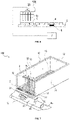
FIG. 1 is a perspective view showing a raw material discharge device according to a first embodiment of the present invention; -
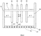
FIG. 2 is a front view of the raw material discharge device according to the first embodiment of the present invention as viewed from a discharge port; -
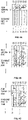
FIGS. 3 is a schematic diagram showing an arrangement example of struts of an adjustment unit provided in the raw material discharge device; -
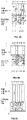
FIGS. 4A to AC are plan views showing an operation of a discharge unit provided in the raw material discharge device; -
FIGS. 5A to 5C are plan views showing the operation of a discharge unit provided in the raw material discharge device; -
FIG. 6 is an explanatory diagram showing a raw material discharge system according to a modification of the raw material discharge device according to an embodiment of the present invention; -
FIG. 7 is a perspective view showing a raw material discharge device according to a second embodiment of the present invention; -
FIG. 8 is an explanatory diagram showing a bias state of the raw material conveyed on a conveyor provided with the raw material discharge device according to the second embodiment of the present invention; -
FIG. 9 is an explanatory diagram showing the bias state of a raw material conveyed on the conveyor provided with the raw material discharge device according to the second embodiment of the present invention; -
FIG. 10A is a plan view showing an arrangement relationship of guide plates arranged on the conveyor; -
FIG. 10B is a side view of the conveyor and the guide plates as viewed from a conveyance direction. -
FIG. 11A is a plan view showing an arrangement relationship of collision plates of a comparative example; and -
FIG. 11B is a side view showing the arrangement relationship of the collision plates of the comparative example viewed from the conveyance direction. - Hereinafter, embodiments of the present invention will be described with reference to the drawings. In the description of the drawings below, the same or similar parts are designated by the same or similar reference numerals. It should be noted that the embodiments shown below exemplify devices and methods for embodying the technical idea of the present invention, and the technical idea of the present invention does not limit structures, arrangement, and the like of components to those described below.
- As shown in
FIG.1 , a rawmaterial discharge device 100 according to a first embodiment of the present invention includes astorage unit 1 which stores a raw material, adischarge unit 2 which discharges the raw material to an outside of thestorage unit 1, and anadjustment unit 3 which adjusts an amount of the raw material to be discharged by holding a part of the raw material. - The
storage unit 1 has a discharge port at one end thereof. Thestorage unit 1 includes arear surface 12,side surfaces bottom surface 15. The raw material is provided on thebottom surface 15 of thestorage unit 1. - The
discharge unit 2 is provided on thebottom surface 15 of thestorage unit 1. As thedischarge unit 2, a so-called floor plate movable fixed-quantity feeder is used. For example, thedischarge unit 2 includes a plurality ofguides 21 arranged at thebottom surface 15 of thestorage unit 1 and extend from therear surface 12 side to thedischarge port 11 side of thestorage unit 1 approximately in parallel with each other at an interval therebetween, a plurality ofslats 22 provided on theguides 21 so as to cover theguides 21 and discharge the raw material to the outside of thedischarge port 11 by reciprocating in thestorage unit 1 along theguides 21 between thedischarge port 11 and therear surface 12, and a drive unit (not shown) configured to drive reciprocating movement of the plurality ofslats 22. - As the plurality of
slats 22 of thedischarge unit 2 moves back and forth between thedischarge port 11 and therear surface 12, the raw material stored in thestorage unit 1 is gradually pushed toward thedischarge port 11 and then discharged out of thedischarge port 11. - As shown in
Fig. 1 , theadjustment unit 3 is provided above thedischarge unit 2 near thedischarge port 11 and includes a plurality ofstruts 31 extending from above to below thedischarge unit 2. Theadjustment unit 3 adjusts an amount of the raw material to be discharged by holding a part of the raw material with thestruts 31. Theadjustment unit 3 includes astrut fixing unit 32 which is fixed between opposing side surfaces 13, 14 of thestorage unit 1 and fixing the plurality of thestruts 31 thereon, and a height adjustment unit (not shown) which adjusts a height of thestruts 31 from the bottom surface of thestorage unit 1. - The
strut fixing unit 32 may have an arbitrary structure without being limited to the example ofFIG. 1 as long as thestrut fixing unit 32 can fix the plurality ofstruts 31 to a predetermined position so that the plurality ofstruts 31 are not moved to thedischarge port 11 side by receiving pressure of the raw material put out from therear surface 12 side to thedischarge port 11 side. - In the example of
FIG. 1 , a columnarstrut fixing unit 32 is bridged between theside surface 13 and theside surface 14, and the plurality ofstruts 31 are respectively housed in a plurality of openings provided in thestrut fixing unit 32. The height of thestruts 31 can be fixed at any height by the height adjustment unit which is composed of a fixture (not shown) such as a bolt and a flange provided in thestrut fixing unit 32 near the openings. - A
height detection unit 33 which detects the height of each of thestruts 31 from a floor, which t is an upper surface of theslat 22, may be provided on thestrut fixing unit 32. For example, a microwave sensor or the like may be used as theheight detection unit 33. Acontrol device 34 that can change the height of thestruts 31 according to a storage state of the raw material by controlling theheight detection unit 33 that adjusts the height of the struts based on a detection result of theheight adjustment unit 33 may be provided. - Distances d1 and d2 of the plurality of
struts 31 and heights HI and H2 from the floor may be adjusted depending on types of the raw material to be discharged. In particular, as a result of diligent study to smoothly convey and discharge the raw materials such as the electronic and electrical device component scraps in which the raw materials having various shapes, specific gravities, and shapes are mixed, without any stagnation of the raw materials, it was found that it is effective to adjust a distance, a ratio of distances, a height and a ratio of heights of each of the plurality of thestruts 31. - The present inventor has examined and found that when the raw material having various shapes, specific gravities, and shapes, such as the electronic and electrical device component scraps, are stored in the
raw discharge device 100 as shown inFIG. 1 , as the discharging operation progresses, the raw material in the vicinity of the side surfaces 13, 14 are not discharged properly and become stagnant, and the stagnant raw material may further entangled with the raw material in the central portion and may not be discharged properly, resulting in clogging (bridging). - In the present embodiment, as shown in
FIG. 2 , it is preferable to respectively adjust a ratio (d1/d2) of a distance (d1) between astrut 31 closest to theside surface side surface storage unit 1 to a narrowest distance (d2) between thestruts 31 in a center portion, and a ratio (H1/H2) of a height (H1) of thestrut 31 closest to theside surface storage unit 1 from the floor to a minimum height (H2) of astrut 31 other than thestrut 31 closest to theside surface storage unit 1 of the floor, so as to prevent clogging of the raw material near theside surface storage unit 1. - More specifically, it is preferable to arrange the plurality of
struts 31 so that H1/H2 = 3 to 10 when d1≤d2, and 0.3 or more is preferable when dl/d2 is 1 or less. It is preferable to arrange the plurality ofstruts 31 so that H1/H2 = 0.5 to 3 when d1≥d2, and 5 or less is preferable when d1/d2 is greater than 1. This provides the rawmaterial discharge device 100 capable of efficiently dispensing a fixed amount of raw material at each time, which is a mixture of raw materials of various shapes, specific gravities, and shapes. - The number of
struts 31 is not limited, but can be, for example, 3 to 10, preferably 3 to 8, and even more preferably 4 to 6. The heights H1 and H2 of each strut 31 from thebottom surface 15 are adjusted according to the condition of the raw material. In this embodiment, the "distance d2 between thestruts 31 in the center portion" refers to the distance between thestrut 31 closest to the center portion and the nextclosest strut 31 to the center portion in the horizontal direction of thestorage unit 1. - The height of each of the
struts 31 may be changed so that they are at different heights along the horizontal direction according to a stagnation of the raw material. For example, as shown inFig. 3 , if the raw materials are stuck near thestrut 31 at the center portion and are difficult to discharge, the height of thestrut 31 at the center portion may be made higher than the height of thestruts 31 of theside surface side surface 13 to theside surface 14 of thestorage unit 1 can be 300 to 500 m, and the height H from a top surface of thedischarge unit 2 to the lower end of thestruts 31 can be 500 mm to 800 mm. - In the example of
FIG. 1 , an example is described in which anadjustment unit 3 for adjusting the amount of the raw material to be put out to the outside of thestorage unit 1 while holding the raw material in thestorage part 1 is provided at one place on the side of thedischarge port 11. However, it is preferable that a plurality of theadjustment part 3, preferably two or more, or even three or more, at a certain interval from thedischarge port 11 side to therear surface 12 side. By providing a plurality of stages of theadjustment parts 3 and adjusting the heights of thestruts 31 provided with therespective adjustment units 3, the raw material can be controlled so as to be smoothly put out while suppressing the congestion of the raw material. In particular, the height of the raw material in front of theadjustment unit 3 may be preferably 1.3 to 5 times as large as H2, and more preferably 3 times or less. - First, when discharging the raw material by using the
material discharge device 100 as shown inFIG. 1 , place the raw material on thebottom surface 15 of thestorage unit 1, and then drive thedischarge unit 2 by the drive unit not shown in the figure. Specifically, as shown inFIG. 4A , at first, all theslats 22 are moved from thedischarge port 11 side to therear surface 12 side so that theguides 21 placed below theslats 22 near thedischarge port 11 side are exposed. Next, as shown inFIG. 4B , all theslats 22 are moved from therear surface 12 side to thedischarge port 11 side while holding the material contained in therear surface 12 side so that the raw material is transported to thedischarge port 11 side. - As shown in
FIG. 4C , some of theslats 22 are moved from thedischarge port 11 side to therear surface 12 side. In this embodiment, an example of threeadjacent slats 22 operating as one set is shown, but of course this is not limited to this example. In the example ofFIG. 4C , theleftmost slat 22 and thefourth slat 22 from the left are moved to therear surface 12 side, and the raw material is held on the leftmost guides 21 and the fourth guides 21 from the left. - The
slat 22 adjacent to theslat 22 that moved to therear side 12 side inFIG. 4C , that is, thesecond slat 22 from the left and thefifth slat 22, are moved from thedischarge port 11 side to therear surface 12 side as shown inFIG. 5A . Some of the raw material is held on theguides 21. As shown inFIG 5B , thethird slat 22 and thesixth slat 22 from the left are moved to therear surface 12 side. After allslats 22 are moved to therear surface 12 side, allslats 22 are moved to thedischarge port 11 side as shown inFIG 5C . As a result of this movement, the raw material on theguides 21 is pushed to thedischarge port 11 and stored in acontainer 4 located below thedischarge port 11. By repeating the operation fromFIG. 4A to FIG 5C multiple times, a certain amount of material is evenly distributed to a plurality ofcontainers 4. Thecontainers 4 are transported by a conveyor such as a belt conveyor, as shown inFIG. 1 . - According to the raw
material discharge device 100 and the discharging method of the first embodiment of the present invention, it is possible to provide a rawmaterial discharge device 100 and a method of processing the electronic and electrical device component scrap, which are capable of efficiently discharging a raw material having various shapes, specific gravities and shapes in each fixed amount. - The raw
material discharge device 100 may, for example, include a measuringunit 6 that measures a weight of thecontainer 4 on theconveyer 5 that conveys thecontainer 4 containing the raw material discharged from thestorage unit 1, as shown inFIG. 6 . The weight information of the raw material in thecontainer 4 measured by the measuringunit 6 is sent to a rawmaterial adjustment unit 7 composed of a general-purpose computer and the like, and the measurement result by the measuringunit 6 is analyzed by the rawmaterial adjustment unit 7. Based on the results of this analysis, thedrive unit 23, which drives the reciprocating movement of a plurality ofslats 22, adjusts the number of reciprocating movements of the plurality ofslats 22. As a result, the amount of the raw material stored in thecontainer 4 is adjusted so that it becomes more appropriate in weight. According to the system as shown inFIG. 6 , an appropriate amount of the raw material depending on the processing capacity of a sorter for processing the raw material can be adjusted according to the types of the raw material so as to be accommodated in thecontainer 4. Highly efficient processing can be performed. - As shown in
FIG.7 , a rawmaterial discharge device 100 according to a second embodiment of the present invention includes a rawmaterial discharge unit 10, aconveyer 5 having aconveyance surface 50 to convey theraw material 40 discharged by thedischarge unit 10, and two ormore guide plates conveyer 5 so as to project from both ends of theconveyance surface 50. - The raw
material discharge unit 10 includes astorage unit 1 for storing araw material 40, adischarge unit 2 for discharging theraw material 40 to the outside of the storage unit1, and anadjustment unit 3 for adjusting an amount of the raw material to be discharged from the discharge port while holding a part of the raw material. - The
storage unit 1 has adischarge port 11 at one end to discharge theraw material 40. Thestorage unit 1 includes arear surface 12, side surfaces 13, 14 opposing with each other, and abottom surface 15. Theraw material 40 is provided on thebottom surface 15 of thestorage unit 1. Thedischarge unit 2 is provided at thebottom surface 15 of thestorage unit 1. As for thedischarge unit 2, a so-called floor plate moving type metering feeder may be used. - For example, the
discharge unit 2 includes a plurality ofguides 21 that is arranged at thebottom surface 15 of thestorage unit 1 and extends from therear surface 12 side to thedischarge port 11 side of thestorage unit 1 approximately in parallel with each other at an interval therebetween, a plurality ofslats 22 provided on theguides 21 so as to cover theguides 21 and discharge theraw material 40 to the outside of thedischarge port 11 by reciprocating in thestorage unit 1 between thedischarge port 11 and therear surface 12, and a drive unit (not shown) configured to drive reciprocating movement of the plurality ofslats 22. - As the plurality of
slats 22 of thedischarge unit 2 moves back and forth between thedischarge port 11 and therear surface 12, theraw material 40 stored in thestorage unit 1 is gradually pushed toward thedischarge port 11 and then discharged out of thedischarge port 11. - The
adjustment unit 3 is provided above thedischarge unit 2 near thedischarge port 11 and includes a plurality ofstruts 31 extending from above to below thedischarge unit 2. Theadjustment unit 3 adjusts an amount of the raw material to be discharged out of thestorage unit 1 while holding a part of the raw material with thestruts 31. Theadjustment unit 3 includes astrut fixing unit 32 which is fixed between opposing side surfaces 13, 14 of thestorage unit 1 which fixes the plurality of thestruts 31 thereon, and a height adjustment unit (not shown) which adjusts a height of thestruts 31 from thebottom surface 15 of thestorage unit 1. - The
strut fixing unit 32 may have an arbitrary structure without being limited to the example ofFIG. 7 as long as thestrut fixing unit 32 can fix the plurality ofstruts 31 to a predetermined position so that the plurality ofstruts 31 are not moved to thedischarge port 11 side by receiving pressure of the raw material put out from therear surface 12 side to thedischarge port 11 side. - In the example of
FIG. 7 , a columnarstrut fixing unit 32 is bridged between theside surface 13 and theside surface 14, and the plurality ofstruts 31 are respectively housed in a plurality of openings provided in thestrut fixing unit 32. The height of thestruts 31 can be fixed at any height by the height adjustment unit which includes a fixture (not shown) such as a bolt and a flange provided in thestrut fixing unit 32 near the openings. - A
height detection unit 33 which detects the height of each of thestruts 31 from a floor, that is, an upper surface of theslat 22 may be provided on thestrut fixing unit 32. For example, a microwave sensor or the like may be used as theheight detection unit 33. Acontrol device 34 that can change the height of thestruts 31 according to a storage state of theraw material 40 by controlling theheight detection unit 33 that adjusts the height of the struts based on a detection result of theheight adjustment unit 33 may be provided. - When the
raw material 40 having various shapes, specific gravities, and shapes, such as the electronic and electrical device component scraps, are stored in theraw discharge device 100 as shown inFIG. 7 , as the discharging operation progresses, theraw material 40 near the side surfaces 13, 14 may not discharged properly and become stagnant, and the stagnantraw material 40 may further entangled with theraw material 40 in the central portion and may not be discharged properly, resulting in clogging (bridging). - In the present embodiment, as shown in
FIG. 8 , it is preferable to adjust a ratio (d1/d2) of a distance (d1) between astrut 31 closest to theside surface side surface storage unit 1 to a narrowest distance (d2) between thestruts 31 in a center portion, and a ratio (H1/H2) of a height (H1) of thestrut 31 closest to theside surface storage unit 1 from the floor to a minimum height (H2) of astrut 31 other than thestrut 31 closest to theside surface storage unit 1 from the floor so as to prevent clogging of the raw material near theside surface storage unit 1. - More specifically, it is preferable to arrange the plurality of
struts 31 so that H1/H2 = 3 to 10 when d1≤d2, and it is preferable to arrange the plurality ofstruts 31 so that H/1H2 = 0.5 to 3 when d1>d2. This provides the rawmaterial discharge device 100 capable of efficiently dispensing a fixed amount of raw material at each time, which is a mixture of raw materials of various shapes, specific gravities, and shapes. - The number of
struts 31 is not limited, but can be, for example, 3 to 10, preferably 3 to 8, and even more preferably 4 to 6. The heights H1 and H2 of each strut 31 from thebottom surface 15 are adjusted according to the condition of the raw material. - The height of each of the
struts 31 may be changed so that they are at different heights along the horizontal direction according to the stagnation of the raw material. For example, as shown inFig. 8 , if the raw materials are stuck near thestrut 31 at the center portion and are difficult to discharge, the height of thestrut 31 at the center portion may be made higher than the height of thestruts 31 of theside surface side surface 13 to theside surface 14 of thestorage unit 1 can be 300 to 500 m, and the height H from a top surface of thedischarge unit 2 to the lower end of thestruts 31 can be 500 mm to 800 mm - In the example of
FIG. 7 , an example is described in which anadjustment unit 3 for adjusting the amount of the raw material 40 (not shown) to be put out to the outside of thestorage unit 1 while holding the raw material in thestorage part 1 is provided at one place on the side of thedischarge port 11. However, it is preferable that a plurality of theadjustment part 3, preferably two or more, or even three or more, at a certain interval from thedischarge port 11 side to therear surface 12 side. By providing a plurality of stages of theadjustment parts 3 and adjusting the heights of thestruts 31 provided with therespective adjustment units 3, theraw material 40 can be controlled so as to be smoothly put out while suppressing the congestion of theraw material 40. - When discharging the raw material by using the
material discharge device 100 as shown inFIG. 7 , at first, place theraw material 40 on thebottom surface 15 of thestorage unit 1, and then drive thedischarge unit 2 by the drive unit which is not shown in the figure. Specifically, as shown inFIG. 4A , all theslats 22 are moved from thedischarge port 11 side to therear surface 12 side so that theguides 21 placed below theslats 22 near thedischarge port 11 side are exposed. Next, as shown inFIG. 4B , all theslats 22 are moved from therear surface 12 side to thedischarge port 11 side while holding the material contained in therear surface 12 side so that the raw material is transported to thedischarge port 11 side. - As shown in
FIG. 4C , some of theslats 22 are moved from thedischarge port 11 side to therear surface 12 side. In this embodiment, an example of threeadjacent slats 22 operating as one set is shown, but of course this is not limited to this example. In the example ofFIG. 4C , theleftmost slat 22 and thefourth slat 22 from the left are moved to therear surface 12 side, and theraw material 40 is held on the leftmost guides 21 and the fourth guides 21 from the left. - The
slat 22 adjacent to theslat 22 that moved to therear side 12 side inFIG. 4C , that is, thesecond slat 22 from the left and thefifth slat 22, are moved from thedischarge port 11 side to therear surface 12 side as shown inFIG. 5A . Some of the raw material is held on theguides 21. As shown inFIG 5B , thethird slat 22 and thesixth slat 22 from the left are moved to therear surface 12 side. After allslats 22 are moved to therear surface 12 side, allslats 22 are moved to thedischarge port 11 side as shown inFIG 5C . As a result of this movement, theraw material 40 on theguides 21 is pushed to thedischarge port 11 and stored in acontainer 4 located below thedischarge port 11. - According to the raw
material discharge device 10 as shown inFIG. 7 , by repeating the operation fromFIG. 4A to FIG 5C multiple times, an almost constant amount ofraw material 40 is distributed onto theconveyance surface 50 at the end of each reciprocating motion of theslats 22, making it possible to keep the discharge amount almost constant at all times. - In addition, as shown in
FIG. 9 , when it is focused on a placement condition of theraw material 40 on theconveyance surface 50 of theconveyor 5, the amount of theraw material 40 discharged with one-time discharge by using theslats 22 may vary along the conveyance direction of theconveyance surface 50 of theconveyor 5. When the amount of theraw material 40 discharged by the one-time discharge varies along the conveyance direction of theconveyance surface 50 of theconveyor 5, the amount of theraw material 40 fed into the sorting machine or the like which is at the destination of theconveyor 5 may vary over time, which may impair the stability of the sorting process. - According to the raw
material discharge device 100 of the second embodiment, two ormore guide plates conveyor 5, which are separated in the conveyance direction of theconveyor 5. As shown inFig. 10A , as theraw material 40 to be discharged from the rawmaterial discharge unit 10 is brought into contact with theseguide plates raw material 40 is adjusted so that the flow of theraw material 40 meanders in the conveying direction, the bias of theraw material 40 can be averaged, and the volume of theraw material 40 conveyed by theconveyor 5 can be averaged in the conveyance direction. As a result, even when theconveyor 5 conveysraw materials 40 that are a mixture of various shapes, specific gravities, and shapes, it is possible to pay out theraw materials 40 more evenly.
even when theconveyor 5 conveysraw materials 40 that are a mixture of various shapes, specific gravities, and shapes, it is possible to pay out theraw materials 40 more evenly. - As shown in
Fig. 10A , theguide plates conveyance surface 50 toward a center of theconveyance surface 50. In the example ofFig. 10A , theguide plates raw material 40 can be conveyed more smoothly while suppressing clogging of the raw material 40 (not shown) near theguide plates guide plates - The shapes of the
guide plates raw material 40 in which theraw materials 40 having various shapes, specific densities, and shapes are mixed, while suppressing the clogging of theraw materials 40 in the vicinity of theguide plates guide plates conveyance surface 50 may be 20 to 40%, more preferably 25 to 35% with respect to the length W of theconveyance surface 50 in the width direction and that makes it possible to more smoothly while suppressing clogging of theraw material 40 in the vicinity of theguide plates - As shown in
FIG. 10B , the heights h1 and h2 of theguide plates conveyance surface 50 at the end of theconveyor 5 are higher than the maximum height of theraw material 40 discharged on theconveyance surface 50. Accordingly, theraw material 40 can be meandered and averaged more reliably. The heights h1 and h2 may be the same as or lower than the height of the side guides 9 provided on both sides of theconveyor 5, but specifically, the heights h1 and h2 may be 250 to 500 mm, and in one embodiment, 300 to 450 mm. - If an interval d12 in which the
guide plates raw material 40 is likely to be clogged, and there is a problem that it is difficult to take measures when theraw material 40 is clogged. If the interval d12 is wide, there is no particular problem, but if it is too wide, the equipment becomes longer. The length may be adjusted according to an installation location. As shown inFIG. 10A , theguide plates - Further, if the distance of the
guide plate 8a closest to the rawmaterial dispensing unit 10 is too short, there may be no margin for eliminating the variation. If it is too far, there may be no problem but it is not preferable because the line becomes longer. As shown inFIG. 10A , the distance d11 from the rawmaterial dispensing section 10 of theguide plate 8a closest to the rawmaterial discharge unit 10 is preferably 200 mm or more, and preferably 300 mm or more. - The materials of the
guide plates guide plates raw materials 40 of various shapes, specific densities, and shapes are mixed, However, it is preferable to be made of metal, for example, aluminum or SUS, since the electronic and electrical device component scraps include metals and that may cause the wear of the plastics or the like. - As shown in
FIGS. 11A and 11B , when thecollision plate 80 for adjusting the height of theraw material 40 was arranged on theconveyor 5, theraw material 40 was clogged and theraw material 40 was not smoothly conveyed. Even when thecollision plate 80 was diagonally arranged on theconveyor 5, the clogging of theraw material 40 was not cleared. - According to the raw
material discharge device 100 of the second embodiment, it becomes possible to more uniformly and smoothly convey theraw material 40 in which 40 in which theraw materials 40 having various shapes, specific densities, and shapes are mixed, by arranging theguide plates FIG. 10A . - The raw
material discharge device 100 as shown inFIGS. 1 to 10 can be particularly suitable as an apparatus for sorting the electronic and electrical device component scrap having an amount that can be processed by sorting machines, before the electronic and electrical device component scrap is sorted by various sorting machines such as a wind power sorting machine, a metal sorter, a color sorter, and a sieving machine. - As used herein, the "electronic and electrical device component scrap" refers to scrap obtained by crushing electronic and electrical devices such as waste home electric appliances, PCs, and mobile phones, recovering them and then crushing them to have an appropriate size. In the present embodiment, the crushing for obtaining the electronic and electrical device component scrap may be performed by an operator. However, crushed objects may be purchased on the market.
- The crushing method is carried out by any apparatus that is not limited to a specific apparatus, and may be carried out in sharing or shock manner. It is desirable to carry out crushing such that the shape of the component is maintained as much as possible. The apparatus does not include one belonging to the category of a crusher for the purpose of fine crashing.
- The electronic and electrical device component scrap can be classified into component scrap including synthetic resins (plastics) used for substrates, parts such as ICs and connectors, and casings; wire scraps; metals; film-shaped component scrap; powders generated by crushing or pulverizing; and others, and they can be further classified into subclasses depending on purposes of the processing. In the present embodiment, the electronic and electrical device component scrap that has been crushed to have a particle diameter of 100 mm or less, more typically 50 mm or less, typically 10 mm or more, or 15 mm or more and has a percentage of individual components separated as component scrap of 70% or more may preferably be processed, although not limited thereto.
- By using the raw
material discharge device 100 according to the embodiment of the present invention to discharge the component scraps composed of various types in fixed quantities, it is possible to efficiently discharge theraw materials 40 that are a mixture of the raw materials of various shapes, specific gravities, and shapes. Then theraw material 40 to be supplied to the subsequent sorting and treatment processes can be supplied more smoothly. Furthermore, by processing eachraw material 40 in a predetermined order, for example, when the sorted material is to be used in the copper smelting process, it is possible to obtain araw material 40 enriched with valuable metals including gold, silver, platinum, palladium, and copper while minimizing substances of smelting inhibitors that are undesirable for processing in the copper smelting process, such as elements such as antimony (Sb) and nickel (Ni), resins, aluminum (Al), iron (Fe), and the like. - Thus, the present invention is not limited to each embodiment, and the components may be modified and embodied without departing from the spirit of the present invention. Further, various inventions may be created by appropriately combining the plurality of components disclosed in the present embodiment. For example, some components may be removed from all the components shown in the embodiments, or the components of different embodiments may be optionally combined.
-
- 1
- Storage unit
- 2
- Discharge unit
- 3
- Adjustment unit
- 4
- Container
- 5
- Conveyor
- 6
- Measuring unit
- 7
- Raw material adjustment unit
- 8a, 8b
- Guide plate
- 9
- Side guide
- 10
- Raw material discharge unit
- 11
- Discharge port
- 12
- Rear surface
- 13
- Side surface
- 14
- Side surface
- 15
- Bottom surface
- 21
- Guide
- 22
- Slats
- 23
- Drive unit
- 31
- Struts
- 32
- Slat fixing unit
- 33
- Height detection unit
- 34
- Control device
- 50
- Conveyance surface
- 80
- Collision plate
- 100
- Material discharge device
Claims (13)
- A raw material discharge device comprising:a storage unit which stores a raw material and comprising a discharge port at one end;a discharge unit arranged at a bottom surface of the storage unit, which conveys the raw material toward the discharge port and discharges the raw material to an outside of the storage unit;an adjustment unit comprising a plurality of struts extending from above to below the discharge unit and adjusting an amount of the raw material to be discharged by holding a part of the raw material with the struts;wherein a ratio (d1/d2) of a distance(d1) between a strut closest to a side surface of the storage unit and the side surface of the storage unit to a narrowest distance (d2) between the struts in a center portion of the storage unit, and a ratio (H1/H2) of a height (H1) of the strut closest to the side surface of the storage unit from a floor to a minimum height (H2) of a strut other than the strut closest to the side surface of the storage unit from the floor are respectively adjustable so as to prevent clogging of the raw material being discharged to the outside of the storage unit.
- The raw material discharge device according to claim 1, wherein it is adjusted so that H1/H2= 3 to 10 when d1≤d2, and it is adjusted so that H1/H2=0.5 to 3 when d1>d2.
- The raw material discharge device according to claim 1 or 2, wherein the adjustment unit comprises:a strut fixing unit fixed between opposing side surfaces of the storage unit, fixing the plurality of struts; anda height adjustment unit adjusting a height of the struts from a bottom surface of the storage unit.
- The raw material discharge device according to any one of claims 1 to 3, wherein the discharge unit comprises:a plurality of guides provided at a bottom surface of the storage unit extending from a rear surface side to a discharge port side of the storage unit having an interval therebetween;a plurality of slats reciprocating in the storage unit along the guides and discharging the raw material out of the storage unit; anda drive unit configured to drive reciprocating movement of the plurality of slats.
- The raw material discharge device according to any one of claims 1 to 4, further comprising:a container containing the raw material discharged from the storage unit;a conveyer conveying the container;a measuring unit measuring a weight of the container; and
a raw material adjustment unit adjusting the amount of the raw material contained in the container based on a measurement result of the measuring unit. - A raw material discharge device comprising:a raw material discharge unit comprising: a storage unit which stores a raw material and comprising a discharge port at one end; a discharge unit arranged at a bottom surface of the storage unit, conveying the raw material toward the discharge port and discharging the raw material to an outside of the storage unit; and an adjustment unit comprising a plurality of struts extending from above to below the discharge unit and adjusting an amount of the raw material to be discharged by holding a part of the raw material with the struts;a conveyer comprising a conveyance surface to convey the raw material discharged from the discharge port; andtwo or more guide plates arranged apart from each other in a conveyance direction of the conveyor and arranged on the conveyor so as to alternately project from both ends of the conveyor surface.
- The raw material discharge device according to claim 6, wherein the guide plates have a length along a width direction of the conveyance surface that is 20 to 40% of a total length in the width direction of the transport surface, respectively.
- The raw material discharge device according to claim 6 or 7, wherein the guide plates are placed at a distance of 300 mm or more in the conveyance direction.
- The raw material discharge device according to any one of claim 6 to 8, wherein one of the guide plates that is most adjacent to the raw material discharge unit is 200 mm or more away from the raw material discharge unit.
- The raw material discharge device according to any one of claim 6 to 9, wherein the guide plats are made of metal.
- The raw material discharge device according to any one of claim 1 to 10, wherein the raw material comprises an electronic/electrical device component scrap.
- A method of processing an electronic and electrical device component scrap comprising:storing electronic and electrical device component scraps in a storage unit to store a raw material, the storage unit comprising a discharge port provided at one end to discharge the raw material;conveying the electronic and electrical device component scraps toward the discharge port by a discharge unit arranged at a bottom surface of the storage unit and discharging the electronic and electrical device component scraps to an outside of the storage unit while holding a part of the electronic and electrical device component scraps by adjusting a distance between a plurality of struts extending from above to below the discharge unit.
- A raw material discharging method of an electronic and electrical device component scrap comprising:storing electronic and electrical device component scraps in a storage unit to store a raw material, the storage unit comprising a discharge port provided at one end to discharge the raw material;conveying the electronic and electrical device component scraps toward the discharge port by a discharge unit arranged at a bottom surface of the storage unit;discharging the electronic and electrical device component scraps to a conveyor arranged below the storage unit while holding a part of the electronic and electrical device component scraps by adjusting a distance between a plurality of struts extending from above to below the discharge unit; andaveraging a height of the raw material by meandering a flow of the raw material by bringing the raw material into contact with two or more guide plates arranged along a conveyance direction of the conveyor so as to be alternately projected from both ends of a conveyance surface of the conveyor.
Applications Claiming Priority (3)
| Application Number | Priority Date | Filing Date | Title |
|---|---|---|---|
| JP2019104043A JP7129949B2 (en) | 2019-06-03 | 2019-06-03 | Raw material dispensing device and processing method for scrap electronic and electrical equipment parts |
| JP2020043351A JP7463141B2 (en) | 2020-03-12 | 2020-03-12 | Raw material dispensing device and raw material dispensing method for scrap electronic and electrical equipment parts |
| PCT/JP2020/021821 WO2020246479A1 (en) | 2019-06-03 | 2020-06-02 | Raw material discharge device, method of processing of electronic/electrical device component scrap, and method of raw material discharge for electronic/electrical device component scrap |
Publications (2)
| Publication Number | Publication Date |
|---|---|
| EP3978155A1 true EP3978155A1 (en) | 2022-04-06 |
| EP3978155A4 EP3978155A4 (en) | 2023-07-12 |
Family
ID=73653243
Family Applications (1)
| Application Number | Title | Priority Date | Filing Date |
|---|---|---|---|
| EP20819496.9A Withdrawn EP3978155A4 (en) | 2019-06-03 | 2020-06-02 | Raw material discharge device, method of processing of electronic/electrical device component scrap, and method of raw material discharge for electronic/electrical device component scrap |
Country Status (7)
| Country | Link |
|---|---|
| US (1) | US11993464B2 (en) |
| EP (1) | EP3978155A4 (en) |
| KR (1) | KR20220004828A (en) |
| CN (1) | CN113727787B (en) |
| CA (1) | CA3142590C (en) |
| TW (1) | TWI762942B (en) |
| WO (1) | WO2020246479A1 (en) |
Family Cites Families (36)
| Publication number | Priority date | Publication date | Assignee | Title |
|---|---|---|---|---|
| US2428852A (en) * | 1943-12-18 | 1947-10-14 | Muir | Sand blender |
| US2543519A (en) * | 1946-08-22 | 1951-02-27 | Joy Mfg Co | Material handling apparatus |
| US3750861A (en) * | 1971-12-13 | 1973-08-07 | R Holtsclaw | Selective discharge feed conveyor |
| DE2450471A1 (en) * | 1974-10-24 | 1976-05-06 | Siempelkamp Gmbh & Co | Bulk material discharge mechanism from hopper - has friction plates between and upstream of toothed rollers |
| US3973573A (en) * | 1974-10-31 | 1976-08-10 | The Macleod Company | Scrap washing system |
| US4436226A (en) * | 1981-08-06 | 1984-03-13 | Aggen Alvin F | Material metering device |
| JP2565561Y2 (en) * | 1993-01-06 | 1998-03-18 | 日本鋼管株式会社 | Belt conveyor powder fall prevention device |
| JP2946170B2 (en) * | 1993-12-30 | 1999-09-06 | 株式会社イナックス | Forming method of double-layer tile |
| JP3617692B2 (en) | 1994-06-09 | 2005-02-09 | 株式会社 日立ディスプレイズ | Liquid crystal display device, liquid crystal projection display device, and optical element |
| JP3535629B2 (en) * | 1995-09-12 | 2004-06-07 | 日鉱金属株式会社 | Recycling of valuable metals from scraps |
| JPH09208035A (en) | 1996-02-06 | 1997-08-12 | Morita:Kk | Supply equipment such as collection bottles |
| DE19645777C2 (en) * | 1996-11-07 | 1998-09-10 | Andreas Haesler | Box feeder |
| JP2955268B1 (en) * | 1998-03-20 | 1999-10-04 | 義則 上堀内 | Quantitative belt conveyor device |
| JP3688197B2 (en) * | 2000-12-22 | 2005-08-24 | 日野自動車株式会社 | Small parts alignment device |
| JP2003054766A (en) | 2001-08-16 | 2003-02-26 | Ebara Corp | Storage facility and storing method |
| JP4212873B2 (en) * | 2002-11-22 | 2009-01-21 | 新日鉄エンジニアリング株式会社 | Raw material supply equipment for rotary hearth furnace |
| JP2005015127A (en) * | 2003-06-25 | 2005-01-20 | Hokko Kakouki Co Ltd | Delivery device |
| DE102004038537B3 (en) * | 2004-08-06 | 2006-02-16 | Aumund-Fördererbau GmbH & Co. KG | Low-dust transfer chute |
| DE102007006133A1 (en) * | 2007-02-03 | 2008-08-07 | Hauni Maschinenbau Ag | Emptying magazine and method for emptying shaft trays filled with rod-shaped products |
| CN201770266U (en) * | 2010-08-13 | 2011-03-23 | 张俊杰 | S-shaped conveyor |
| JP2013230931A (en) * | 2012-05-02 | 2013-11-14 | Kurimoto Ltd | Fixed quantity transfer apparatus |
| TWI555579B (en) * | 2012-11-01 | 2016-11-01 | Taiwan Keyarrow Ind Co Ltd | Conveying crushing device |
| CN104139970B (en) * | 2013-05-08 | 2017-02-01 | 珠海格力电器股份有限公司 | Feeding system |
| JP6050222B2 (en) * | 2013-12-26 | 2016-12-21 | パンパシフィック・カッパー株式会社 | Disposal of electrical and electronic parts waste |
| CN203754018U (en) * | 2013-12-27 | 2014-08-06 | 刘林 | Zipper belt box type feeding machine |
| CN204751428U (en) * | 2015-07-21 | 2015-11-11 | 黄丽川 | Direction formula cap for brush conveyer belt |
| KR20180055907A (en) * | 2016-03-25 | 2018-05-25 | 제이엑스금속주식회사 | Ti-Ta alloy sputtering target and manufacturing method thereof |
| CN206345474U (en) * | 2016-12-16 | 2017-07-21 | 杭州豪伦自动化设备有限公司 | A kind of foodweb |
| CN207057027U (en) * | 2017-08-15 | 2018-03-02 | 重庆炜霖商贸有限公司 | Raw coal separating structure |
| CN207240561U (en) * | 2017-09-30 | 2018-04-17 | 东莞市宝品精密仪器有限公司 | A kind of sizing material circulation conveying mechanism of open mill |
| CN107902433A (en) * | 2017-12-22 | 2018-04-13 | 河南中农福安农业装备有限公司 | A kind of support frame Liftable type arranges grain trolley |
| CN208022279U (en) * | 2018-01-31 | 2018-10-30 | 张家港市翔林机械有限公司 | Sealed link conveyer |
| CN108529177A (en) * | 2018-05-26 | 2018-09-14 | 郑州鼎源自动化科技有限公司 | A kind of quick high accuracy proportioner |
| JP7191362B2 (en) | 2018-08-20 | 2022-12-19 | 株式会社丸和 | Dispensing device for fluid solids |
| CN210299457U (en) * | 2019-07-01 | 2020-04-14 | 芜湖启迪睿视信息技术有限公司 | Automatic tobacco leaf dispersing equipment based on clamping groove speed difference |
| US20230089544A1 (en) * | 2021-09-22 | 2023-03-23 | Republic Services, Inc. | Automated process and method for material separation and recycling |
-
2020
- 2020-06-02 CN CN202080028795.0A patent/CN113727787B/en active Active
- 2020-06-02 WO PCT/JP2020/021821 patent/WO2020246479A1/en not_active Ceased
- 2020-06-02 KR KR1020217039783A patent/KR20220004828A/en not_active Ceased
- 2020-06-02 EP EP20819496.9A patent/EP3978155A4/en not_active Withdrawn
- 2020-06-02 CA CA3142590A patent/CA3142590C/en active Active
- 2020-06-02 US US17/615,994 patent/US11993464B2/en active Active
- 2020-06-03 TW TW109118614A patent/TWI762942B/en active
Also Published As
| Publication number | Publication date |
|---|---|
| CA3142590C (en) | 2024-11-05 |
| WO2020246479A1 (en) | 2020-12-10 |
| CN113727787B (en) | 2023-06-13 |
| CA3142590A1 (en) | 2020-12-10 |
| US20220324657A1 (en) | 2022-10-13 |
| US11993464B2 (en) | 2024-05-28 |
| KR20220004828A (en) | 2022-01-11 |
| CN113727787A (en) | 2021-11-30 |
| TWI762942B (en) | 2022-05-01 |
| TW202108256A (en) | 2021-03-01 |
| EP3978155A4 (en) | 2023-07-12 |
Similar Documents
| Publication | Publication Date | Title |
|---|---|---|
| US11534797B2 (en) | Linear object removal method, linear object removal device, and electronic/electric apparatus component scrap processing method | |
| US11945000B2 (en) | Method for removing linear objects, device for removing linear objects, and method for processing electronic/electrical equipment component waste | |
| KR102524815B1 (en) | Raw material supply device, electronic/electrical device component scrap processing device, and electronic/electrical device component scrap processing method | |
| US11548032B2 (en) | Method for removing wire-form objects, device for removing wire-form objects, and method for processing electronic/electrical apparatus component scrap | |
| US11993464B2 (en) | Raw material discharge device, method of processing of electronic/electrical device component scrap, and method of raw material discharge for electronic/electrical device component scrap | |
| JP6766549B2 (en) | Blast furnace coke supply equipment | |
| JP7463141B2 (en) | Raw material dispensing device and raw material dispensing method for scrap electronic and electrical equipment parts | |
| JP7129949B2 (en) | Raw material dispensing device and processing method for scrap electronic and electrical equipment parts | |
| JP2020037459A (en) | Raw material supply device and processing method for electronic/electrical equipment component scrap | |
| CA3135441C (en) | Sorting machine and method for treating electronic/electric device component scraps | |
| JP2023019790A (en) | Removal device of linear object, removal method of linear object and processing method of electronic/electric apparatus component scrap | |
| JPH0848418A (en) | Transportation method of sintering raw material |
Legal Events
| Date | Code | Title | Description |
|---|---|---|---|
| STAA | Information on the status of an ep patent application or granted ep patent |
Free format text: STATUS: THE INTERNATIONAL PUBLICATION HAS BEEN MADE |
|
| PUAI | Public reference made under article 153(3) epc to a published international application that has entered the european phase |
Free format text: ORIGINAL CODE: 0009012 |
|
| STAA | Information on the status of an ep patent application or granted ep patent |
Free format text: STATUS: REQUEST FOR EXAMINATION WAS MADE |
|
| 17P | Request for examination filed |
Effective date: 20211209 |
|
| AK | Designated contracting states |
Kind code of ref document: A1 Designated state(s): AL AT BE BG CH CY CZ DE DK EE ES FI FR GB GR HR HU IE IS IT LI LT LU LV MC MK MT NL NO PL PT RO RS SE SI SK SM TR |
|
| DAV | Request for validation of the european patent (deleted) | ||
| DAX | Request for extension of the european patent (deleted) | ||
| A4 | Supplementary search report drawn up and despatched |
Effective date: 20230613 |
|
| RIC1 | Information provided on ipc code assigned before grant |
Ipc: C22B 15/00 20060101ALI20230606BHEP Ipc: C22B 7/00 20060101ALI20230606BHEP Ipc: B65G 65/44 20060101ALI20230606BHEP Ipc: B09B 5/00 20060101AFI20230606BHEP |
|
| STAA | Information on the status of an ep patent application or granted ep patent |
Free format text: STATUS: THE APPLICATION IS DEEMED TO BE WITHDRAWN |
|
| 18D | Application deemed to be withdrawn |
Effective date: 20240111 |