EP3978109A1 - Gas solution supply device - Google Patents
Gas solution supply device Download PDFInfo
- Publication number
- EP3978109A1 EP3978109A1 EP21199599.8A EP21199599A EP3978109A1 EP 3978109 A1 EP3978109 A1 EP 3978109A1 EP 21199599 A EP21199599 A EP 21199599A EP 3978109 A1 EP3978109 A1 EP 3978109A1
- Authority
- EP
- European Patent Office
- Prior art keywords
- gas
- liquid separator
- valve
- solution
- line
- Prior art date
- Legal status (The legal status is an assumption and is not a legal conclusion. Google has not performed a legal analysis and makes no representation as to the accuracy of the status listed.)
- Granted
Links
Images



Classifications
-
- B—PERFORMING OPERATIONS; TRANSPORTING
- B01—PHYSICAL OR CHEMICAL PROCESSES OR APPARATUS IN GENERAL
- B01F—MIXING, e.g. DISSOLVING, EMULSIFYING OR DISPERSING
- B01F23/00—Mixing according to the phases to be mixed, e.g. dispersing or emulsifying
- B01F23/20—Mixing gases with liquids
- B01F23/23—Mixing gases with liquids by introducing gases into liquid media, e.g. for producing aerated liquids
- B01F23/232—Mixing gases with liquids by introducing gases into liquid media, e.g. for producing aerated liquids using flow-mixing means for introducing the gases, e.g. baffles
- B01F23/2323—Mixing gases with liquids by introducing gases into liquid media, e.g. for producing aerated liquids using flow-mixing means for introducing the gases, e.g. baffles by circulating the flow in guiding constructions or conduits
-
- B—PERFORMING OPERATIONS; TRANSPORTING
- B01—PHYSICAL OR CHEMICAL PROCESSES OR APPARATUS IN GENERAL
- B01F—MIXING, e.g. DISSOLVING, EMULSIFYING OR DISPERSING
- B01F23/00—Mixing according to the phases to be mixed, e.g. dispersing or emulsifying
- B01F23/20—Mixing gases with liquids
- B01F23/23—Mixing gases with liquids by introducing gases into liquid media, e.g. for producing aerated liquids
-
- B—PERFORMING OPERATIONS; TRANSPORTING
- B01—PHYSICAL OR CHEMICAL PROCESSES OR APPARATUS IN GENERAL
- B01F—MIXING, e.g. DISSOLVING, EMULSIFYING OR DISPERSING
- B01F23/00—Mixing according to the phases to be mixed, e.g. dispersing or emulsifying
- B01F23/20—Mixing gases with liquids
- B01F23/23—Mixing gases with liquids by introducing gases into liquid media, e.g. for producing aerated liquids
- B01F23/232—Mixing gases with liquids by introducing gases into liquid media, e.g. for producing aerated liquids using flow-mixing means for introducing the gases, e.g. baffles
- B01F23/2326—Mixing gases with liquids by introducing gases into liquid media, e.g. for producing aerated liquids using flow-mixing means for introducing the gases, e.g. baffles adding the flowing main component by suction means, e.g. using an ejector
-
- B—PERFORMING OPERATIONS; TRANSPORTING
- B01—PHYSICAL OR CHEMICAL PROCESSES OR APPARATUS IN GENERAL
- B01D—SEPARATION
- B01D19/00—Degasification of liquids
- B01D19/0063—Regulation, control including valves and floats
-
- B—PERFORMING OPERATIONS; TRANSPORTING
- B01—PHYSICAL OR CHEMICAL PROCESSES OR APPARATUS IN GENERAL
- B01D—SEPARATION
- B01D19/00—Degasification of liquids
- B01D19/0068—General arrangements, e.g. flowsheets
-
- B—PERFORMING OPERATIONS; TRANSPORTING
- B01—PHYSICAL OR CHEMICAL PROCESSES OR APPARATUS IN GENERAL
- B01F—MIXING, e.g. DISSOLVING, EMULSIFYING OR DISPERSING
- B01F21/00—Dissolving
- B01F21/30—Workflow diagrams or layout of plants, e.g. flow charts; Details of workflow diagrams or layout of plants, e.g. controlling means
-
- B—PERFORMING OPERATIONS; TRANSPORTING
- B01—PHYSICAL OR CHEMICAL PROCESSES OR APPARATUS IN GENERAL
- B01F—MIXING, e.g. DISSOLVING, EMULSIFYING OR DISPERSING
- B01F23/00—Mixing according to the phases to be mixed, e.g. dispersing or emulsifying
- B01F23/10—Mixing gases with gases
- B01F23/19—Mixing systems, i.e. flow charts or diagrams; Arrangements, e.g. comprising controlling means
-
- B—PERFORMING OPERATIONS; TRANSPORTING
- B01—PHYSICAL OR CHEMICAL PROCESSES OR APPARATUS IN GENERAL
- B01F—MIXING, e.g. DISSOLVING, EMULSIFYING OR DISPERSING
- B01F23/00—Mixing according to the phases to be mixed, e.g. dispersing or emulsifying
- B01F23/20—Mixing gases with liquids
- B01F23/23—Mixing gases with liquids by introducing gases into liquid media, e.g. for producing aerated liquids
- B01F23/231—Mixing gases with liquids by introducing gases into liquid media, e.g. for producing aerated liquids by bubbling
- B01F23/23105—Arrangement or manipulation of the gas bubbling devices
- B01F23/2311—Mounting the bubbling devices or the diffusers
- B01F23/23114—Mounting the bubbling devices or the diffusers characterised by the way in which the different elements of the bubbling installation are mounted
- B01F23/231141—Mounting auxiliary devices, e.g. pumps or compressors in a particular place on the bubbling installation, e.g. under water
-
- B—PERFORMING OPERATIONS; TRANSPORTING
- B01—PHYSICAL OR CHEMICAL PROCESSES OR APPARATUS IN GENERAL
- B01F—MIXING, e.g. DISSOLVING, EMULSIFYING OR DISPERSING
- B01F23/00—Mixing according to the phases to be mixed, e.g. dispersing or emulsifying
- B01F23/20—Mixing gases with liquids
- B01F23/23—Mixing gases with liquids by introducing gases into liquid media, e.g. for producing aerated liquids
- B01F23/231—Mixing gases with liquids by introducing gases into liquid media, e.g. for producing aerated liquids by bubbling
- B01F23/23105—Arrangement or manipulation of the gas bubbling devices
- B01F23/2312—Diffusers
- B01F23/23122—Diffusers having elements opening under air pressure, e.g. valves
-
- B—PERFORMING OPERATIONS; TRANSPORTING
- B01—PHYSICAL OR CHEMICAL PROCESSES OR APPARATUS IN GENERAL
- B01F—MIXING, e.g. DISSOLVING, EMULSIFYING OR DISPERSING
- B01F23/00—Mixing according to the phases to be mixed, e.g. dispersing or emulsifying
- B01F23/20—Mixing gases with liquids
- B01F23/23—Mixing gases with liquids by introducing gases into liquid media, e.g. for producing aerated liquids
- B01F23/232—Mixing gases with liquids by introducing gases into liquid media, e.g. for producing aerated liquids using flow-mixing means for introducing the gases, e.g. baffles
-
- B—PERFORMING OPERATIONS; TRANSPORTING
- B01—PHYSICAL OR CHEMICAL PROCESSES OR APPARATUS IN GENERAL
- B01F—MIXING, e.g. DISSOLVING, EMULSIFYING OR DISPERSING
- B01F23/00—Mixing according to the phases to be mixed, e.g. dispersing or emulsifying
- B01F23/20—Mixing gases with liquids
- B01F23/23—Mixing gases with liquids by introducing gases into liquid media, e.g. for producing aerated liquids
- B01F23/2366—Parts; Accessories
-
- B—PERFORMING OPERATIONS; TRANSPORTING
- B01—PHYSICAL OR CHEMICAL PROCESSES OR APPARATUS IN GENERAL
- B01F—MIXING, e.g. DISSOLVING, EMULSIFYING OR DISPERSING
- B01F23/00—Mixing according to the phases to be mixed, e.g. dispersing or emulsifying
- B01F23/20—Mixing gases with liquids
- B01F23/23—Mixing gases with liquids by introducing gases into liquid media, e.g. for producing aerated liquids
- B01F23/237—Mixing gases with liquids by introducing gases into liquid media, e.g. for producing aerated liquids characterised by the physical or chemical properties of gases or vapours introduced in the liquid media
- B01F23/2376—Mixing gases with liquids by introducing gases into liquid media, e.g. for producing aerated liquids characterised by the physical or chemical properties of gases or vapours introduced in the liquid media characterised by the gas being introduced
- B01F23/23761—Aerating, i.e. introducing oxygen containing gas in liquids
- B01F23/237613—Ozone
-
- B—PERFORMING OPERATIONS; TRANSPORTING
- B01—PHYSICAL OR CHEMICAL PROCESSES OR APPARATUS IN GENERAL
- B01F—MIXING, e.g. DISSOLVING, EMULSIFYING OR DISPERSING
- B01F23/00—Mixing according to the phases to be mixed, e.g. dispersing or emulsifying
- B01F23/20—Mixing gases with liquids
- B01F23/29—Mixing systems, i.e. flow charts or diagrams
-
- B—PERFORMING OPERATIONS; TRANSPORTING
- B01—PHYSICAL OR CHEMICAL PROCESSES OR APPARATUS IN GENERAL
- B01F—MIXING, e.g. DISSOLVING, EMULSIFYING OR DISPERSING
- B01F23/00—Mixing according to the phases to be mixed, e.g. dispersing or emulsifying
- B01F23/70—Pre-treatment of the materials to be mixed
- B01F23/703—Degassing or de-aerating materials; Replacing one gas within the materials by another gas
-
- B—PERFORMING OPERATIONS; TRANSPORTING
- B01—PHYSICAL OR CHEMICAL PROCESSES OR APPARATUS IN GENERAL
- B01F—MIXING, e.g. DISSOLVING, EMULSIFYING OR DISPERSING
- B01F23/00—Mixing according to the phases to be mixed, e.g. dispersing or emulsifying
- B01F23/80—After-treatment of the mixture
- B01F23/803—Venting, degassing or ventilating of gases, fumes or toxic vapours from the mixture
-
- B—PERFORMING OPERATIONS; TRANSPORTING
- B01—PHYSICAL OR CHEMICAL PROCESSES OR APPARATUS IN GENERAL
- B01F—MIXING, e.g. DISSOLVING, EMULSIFYING OR DISPERSING
- B01F25/00—Flow mixers; Mixers for falling materials, e.g. solid particles
- B01F25/30—Injector mixers
- B01F25/31—Injector mixers in conduits or tubes through which the main component flows
-
- B—PERFORMING OPERATIONS; TRANSPORTING
- B01—PHYSICAL OR CHEMICAL PROCESSES OR APPARATUS IN GENERAL
- B01F—MIXING, e.g. DISSOLVING, EMULSIFYING OR DISPERSING
- B01F25/00—Flow mixers; Mixers for falling materials, e.g. solid particles
- B01F25/30—Injector mixers
- B01F25/31—Injector mixers in conduits or tubes through which the main component flows
- B01F25/312—Injector mixers in conduits or tubes through which the main component flows with Venturi elements; Details thereof
- B01F25/3124—Injector mixers in conduits or tubes through which the main component flows with Venturi elements; Details thereof characterised by the place of introduction of the main flow
- B01F25/31243—Eductor or eductor-type venturi, i.e. the main flow being injected through the venturi with high speed in the form of a jet
-
- B—PERFORMING OPERATIONS; TRANSPORTING
- B01—PHYSICAL OR CHEMICAL PROCESSES OR APPARATUS IN GENERAL
- B01F—MIXING, e.g. DISSOLVING, EMULSIFYING OR DISPERSING
- B01F25/00—Flow mixers; Mixers for falling materials, e.g. solid particles
- B01F25/50—Circulation mixers, e.g. wherein at least part of the mixture is discharged from and reintroduced into a receptacle
- B01F25/51—Circulation mixers, e.g. wherein at least part of the mixture is discharged from and reintroduced into a receptacle in which the mixture is circulated through a set of tubes, e.g. with gradual introduction of a component into the circulating flow
-
- B—PERFORMING OPERATIONS; TRANSPORTING
- B01—PHYSICAL OR CHEMICAL PROCESSES OR APPARATUS IN GENERAL
- B01F—MIXING, e.g. DISSOLVING, EMULSIFYING OR DISPERSING
- B01F25/00—Flow mixers; Mixers for falling materials, e.g. solid particles
- B01F25/50—Circulation mixers, e.g. wherein at least part of the mixture is discharged from and reintroduced into a receptacle
- B01F25/53—Circulation mixers, e.g. wherein at least part of the mixture is discharged from and reintroduced into a receptacle in which the mixture is discharged from and reintroduced into a receptacle through a recirculation tube, into which an additional component is introduced
-
- B—PERFORMING OPERATIONS; TRANSPORTING
- B01—PHYSICAL OR CHEMICAL PROCESSES OR APPARATUS IN GENERAL
- B01F—MIXING, e.g. DISSOLVING, EMULSIFYING OR DISPERSING
- B01F35/00—Accessories for mixers; Auxiliary operations or auxiliary devices; Parts or details of general application
- B01F35/20—Measuring; Control or regulation
-
- B—PERFORMING OPERATIONS; TRANSPORTING
- B01—PHYSICAL OR CHEMICAL PROCESSES OR APPARATUS IN GENERAL
- B01F—MIXING, e.g. DISSOLVING, EMULSIFYING OR DISPERSING
- B01F35/00—Accessories for mixers; Auxiliary operations or auxiliary devices; Parts or details of general application
- B01F35/20—Measuring; Control or regulation
- B01F35/22—Control or regulation
- B01F35/221—Control or regulation of operational parameters, e.g. level of material in the mixer, temperature or pressure
- B01F35/2211—Amount of delivered fluid during a period
-
- B—PERFORMING OPERATIONS; TRANSPORTING
- B01—PHYSICAL OR CHEMICAL PROCESSES OR APPARATUS IN GENERAL
- B01F—MIXING, e.g. DISSOLVING, EMULSIFYING OR DISPERSING
- B01F35/00—Accessories for mixers; Auxiliary operations or auxiliary devices; Parts or details of general application
- B01F35/71—Feed mechanisms
- B01F35/717—Feed mechanisms characterised by the means for feeding the components to the mixer
- B01F35/7176—Feed mechanisms characterised by the means for feeding the components to the mixer using pumps
-
- B—PERFORMING OPERATIONS; TRANSPORTING
- B01—PHYSICAL OR CHEMICAL PROCESSES OR APPARATUS IN GENERAL
- B01F—MIXING, e.g. DISSOLVING, EMULSIFYING OR DISPERSING
- B01F35/00—Accessories for mixers; Auxiliary operations or auxiliary devices; Parts or details of general application
- B01F35/71—Feed mechanisms
- B01F35/717—Feed mechanisms characterised by the means for feeding the components to the mixer
- B01F35/71805—Feed mechanisms characterised by the means for feeding the components to the mixer using valves, gates, orifices or openings
-
- B—PERFORMING OPERATIONS; TRANSPORTING
- B01—PHYSICAL OR CHEMICAL PROCESSES OR APPARATUS IN GENERAL
- B01F—MIXING, e.g. DISSOLVING, EMULSIFYING OR DISPERSING
- B01F35/00—Accessories for mixers; Auxiliary operations or auxiliary devices; Parts or details of general application
- B01F35/71—Feed mechanisms
- B01F35/717—Feed mechanisms characterised by the means for feeding the components to the mixer
- B01F35/71805—Feed mechanisms characterised by the means for feeding the components to the mixer using valves, gates, orifices or openings
- B01F35/718051—Feed mechanisms characterised by the means for feeding the components to the mixer using valves, gates, orifices or openings being adjustable
-
- C—CHEMISTRY; METALLURGY
- C01—INORGANIC CHEMISTRY
- C01B—NON-METALLIC ELEMENTS; COMPOUNDS THEREOF; METALLOIDS OR COMPOUNDS THEREOF NOT COVERED BY SUBCLASS C01C
- C01B13/00—Oxygen; Ozone; Oxides or hydroxides in general
- C01B13/10—Preparation of ozone
- C01B13/11—Preparation of ozone by electric discharge
-
- B—PERFORMING OPERATIONS; TRANSPORTING
- B01—PHYSICAL OR CHEMICAL PROCESSES OR APPARATUS IN GENERAL
- B01F—MIXING, e.g. DISSOLVING, EMULSIFYING OR DISPERSING
- B01F2101/00—Mixing characterised by the nature of the mixed materials or by the application field
- B01F2101/58—Mixing semiconducting materials, e.g. during semiconductor or wafer manufacturing processes
-
- C—CHEMISTRY; METALLURGY
- C02—TREATMENT OF WATER, WASTE WATER, SEWAGE, OR SLUDGE
- C02F—TREATMENT OF WATER, WASTE WATER, SEWAGE, OR SLUDGE
- C02F1/00—Treatment of water, waste water, or sewage
- C02F1/72—Treatment of water, waste water, or sewage by oxidation
- C02F1/78—Treatment of water, waste water, or sewage by oxidation with ozone
-
- C—CHEMISTRY; METALLURGY
- C02—TREATMENT OF WATER, WASTE WATER, SEWAGE, OR SLUDGE
- C02F—TREATMENT OF WATER, WASTE WATER, SEWAGE, OR SLUDGE
- C02F2201/00—Apparatus for treatment of water, waste water or sewage
- C02F2201/78—Details relating to ozone treatment devices
- C02F2201/782—Ozone generators
-
- C—CHEMISTRY; METALLURGY
- C02—TREATMENT OF WATER, WASTE WATER, SEWAGE, OR SLUDGE
- C02F—TREATMENT OF WATER, WASTE WATER, SEWAGE, OR SLUDGE
- C02F2201/00—Apparatus for treatment of water, waste water or sewage
- C02F2201/78—Details relating to ozone treatment devices
- C02F2201/784—Diffusers or nozzles for ozonation
-
- H—ELECTRICITY
- H10—SEMICONDUCTOR DEVICES; ELECTRIC SOLID-STATE DEVICES NOT OTHERWISE PROVIDED FOR
- H10P—GENERIC PROCESSES OR APPARATUS FOR THE MANUFACTURE OR TREATMENT OF DEVICES COVERED BY CLASS H10
- H10P70/00—Cleaning of wafers, substrates or parts of devices
Definitions
- the present invention relates to a gas solution supply device for supplying gas solution, and in particular to a technique for achieving a high concentration of gas solution.
- Ozone water has been used for cleaning electronic components such as semiconductor devices and liquid crystal.
- Ozone water is produced by dissolving ozone gas in ultrapure water and then supplied to a use point (such as a semiconductor device factory and an electronic component factory).
- ozone water produced by dissolving ozone gas in ultrapure water is stored in a gas-liquid separator and the ozone water is delivered from the gas-liquid separator to the use point by a pump located at a stage subsequent to the gas-liquid separator (downstream thereof), for example (see Japanese Patent Laid-Open No. 2019-155221 , for instance).
- a conventional device has only one gas-liquid separator and a pump (a pump for delivering ozone water to the use point) is provided subsequent to the gas-liquid separator, a pressure in the gas-liquid separator is difficult to increase, making it difficult to achieve a high concentration of ozone water.
- the pump is an air-driven pump, it is also difficult to suppress fluctuations in delivery pressure of ozone water due to influence of pulsation of the pump.
- An object of the present invention which has been made in view of these challenges, is to provide a gas solution supply device that can achieve a high concentration of gas solution and can suppress fluctuations in the delivery pressure of gas solution.
- a gas solution supply device includes: a first gas-liquid separator in which gas solution is stored; a second gas-liquid separator which is provided at a stage subsequent to the first gas-liquid separator and in which gas solution to be supplied to a use point is stored; an intermediate line provided between the first gas-liquid separator and the second gas-liquid separator; a pressure booster pump that is provided on the intermediate line and increases a pressure of gas solution being supplied from the first gas-liquid separator to the second gas-liquid separator; a gas supply line that supplies gas as a material of the gas solution; and a gas dissolving unit that is provided on the intermediate line and dissolves the gas supplied from the gas supply line in the gas solution supplied from the first gas-liquid separator.
- the pressure booster pump is provided at a stage preceding the second gas-liquid separator, so that the pressure in the second gas-liquid separator can be increased and a high concentration of gas solution is possible.
- providing the second gas-liquid separator at a stage subsequent to the pressure booster pump results in damper effect, making it possible to suppress fluctuations in delivery pressure of gas solution being supplied from the second gas-liquid separator to the use point.
- the first gas-liquid separator may include a circulating supply line for circulating and supplying unused gas solution at the use point.
- unused gas solution at the use point can be recycled and usage of gas as a material of gas solution can be reduced. Since in this case the first gas-liquid separator, to which unused gas solution at the use point is supplied, is provided at a stage preceding the pressure booster pump, there is no need for a pump to increase the pressure of the unused gas solution.
- the first gas-liquid separator may include a liquid supply line through which liquid as a material of the gas solution is supplied, and the liquid supply line may include a second gas dissolving unit that dissolves undissolved excess gas discharged from the second gas-liquid separator in the liquid as a material of the gas solution.
- the gas solution supply device of the present invention may include: a first valve provided on a liquid supply line that supplies liquid as a material of the gas solution; a second valve provided on a gas solution supply line that supplies the gas solution to the use point; a third valve provided on an exhaust line from the first gas-liquid separator to an exhaust port; a fourth valve provided on a drain line branching from the exhaust line; and a control unit that performs open and close control of the first valve, the second valve, the third valve, and the fourth valve.
- the control unit may be configured to: when the gas solution is to be supplied to the use point, perform control to open the first valve, the second valve and the third valve and close the fourth valve, and when the first gas-liquid separator and the second gas-liquid separator are to be cleaned, perform control to close the second valve and the third valve and open the first valve and the fourth valve.
- gas solution can be supplied to the use point by opening the first, the second and the third valves and closing the fourth valve, while the first gas-liquid separator and the second gas-liquid separator can be cleaned by closing the second and the third valves and opening the first and the fourth valves.
- a method according to the present invention is a method for execution in a gas solution supply device, the gas solution supply device including: a first gas-liquid separator in which gas solution is stored; a second gas-liquid separator which is provided at a stage subsequent to the first gas-liquid separator and in which gas solution to be supplied to a use point is stored; an intermediate line provided between the first gas-liquid separator and the second gas-liquid separator; and a pressure booster pump that is provided on the intermediate line and increases a pressure of gas solution being supplied from the first gas-liquid separator to the second gas-liquid separator.
- the method includes the steps of supplying gas as a material of the gas solution to the intermediate line, and dissolving the supplied gas in the gas solution supplied from the first gas-liquid separator.
- This method can also increase the pressure in the second gas-liquid separator and enable a high concentration of gas solution because the pressure booster pump is provided at a stage preceding the second gas-liquid separator as with the device above. Further, providing the second gas-liquid separator at a stage subsequent to the pressure booster pump results in damper effect, making it possible to suppress fluctuations in delivery pressure of gas solution being supplied from the second gas-liquid separator to the use point.
- the gas solution supply device may include: a first valve provided on a liquid supply line that supplies liquid as a material of the gas solution; a second valve provided on a gas solution supply line that supplies the gas solution to the use point; a third valve provided on an exhaust line from the first gas-liquid separator to an exhaust port; and a fourth valve provided on a drain line branching from the exhaust line.
- the method may include: when the gas solution is to be supplied to the use point, opening the first valve, the second valve and the third valve and closing the fourth valve, and when the first gas-liquid separator and the second gas-liquid separator are to be cleaned, closing the second valve and the third valve and opening the first valve and the fourth valve.
- gas solution can be supplied to the use point by opening the first, the second and the third valves and closing the fourth valve, while the first gas-liquid separator and the second gas-liquid separator can be cleaned by closing the second and the third valves and opening the first and the fourth valves.
- the present invention can achieve a high concentration of gas solution and can suppress fluctuations in the delivery pressure of gas solution.
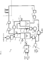
- FIG. 1 illustrates a configuration of the ozone water supply device of this embodiment.
- an ozone water supply device 1 includes a gas supply line 2 through which ozone gas as a material of ozone water is supplied and a liquid supply line 3 through which pure water (DIW) as a material of ozone water is supplied.
- DIW pure water
- the gas supply line 2 is supplied with a first gas (e.g., oxygen gas) and a second gas (e.g., carbon dioxide gas, nitrogen gas, or mixed gas of carbon dioxide gas and nitrogen gas) as materials of ozone gas.
- the gas supply line 2 includes a gas flow rate adjuster 4 and an ozonizer 5.
- the gas flow rate adjuster 4 adjusts a flow rate of the first gas and that of the second gas.
- the ozonizer 5 generates ozone gas from the material gas (mixed gas of the first gas and the second gas) by electric discharge.
- the liquid supply line 3 is supplied with pure water, with the flow rate of the pure water being adjusted by a flow regulating valve 6 and the flow rate of the pure water being measured by a flow sensor 7.
- the liquid supply line 3 is connected with a first gas-liquid separator 8.
- the first gas-liquid separator 8 is connected with a circulating supply line 9, which circulates and supplies unused ozone water at a use point.
- the circulating supply line 9 includes a flow sensor 10 for measuring the flow rate of unused ozone water at the use point and a pressure regulating valve 11 for adjusting a pressure of the unused ozone water at the use point.
- the first gas-liquid separator 8 stores unused ozone water and includes a level sensor 12 for measuring a level of the ozone water.
- the first gas-liquid separator 8 includes an exhaust line 13 for discharging undissolved ozone gas.
- the exhaust line 13 includes an ozone gas decomposer 14 for decomposing ozone gas and a pressure regulating valve 15 for adjusting the pressure of ozone gas being exhausted.
- a second gas-liquid separator 16 in which ozone water to be supplied to the use point is stored is provided at a stage subsequent to (downstream of) the first gas-liquid separator 8, the first gas-liquid separator 8 and the second gas-liquid separator 16 being connected by an intermediate line 17.
- the intermediate line 17 includes a pressure booster pump 18 that increases the pressure of ozone water being supplied from the first gas-liquid separator 8 to the second gas-liquid separator 16, a flow sensor 19 that measures the flow rate of ozone water being supplied to the second gas-liquid separator 16, and a gas dissolving nozzle 20 that dissolves the ozone gas supplied from the gas supply line 2 in the ozone water supplied from the first gas-liquid separator 8.
- the ozone water from the gas dissolving nozzle 20 may be introduced from an upper portion of the second gas-liquid separator 16.
- the ozone water from the gas dissolving nozzle 20 may also be introduced from a lower portion of the second gas-liquid separator 16. In that case, the gas dissolving nozzle 20 is preferably disposed in a lower portion of the second gas-liquid separator 16.
- the pressure booster pump 18 can be a centrifugal pump, a bellows pump, or a diaphragm pump, for example.
- a portion of the pressure booster pump 18 that makes contact with ozone water and/or ozone gas is made of a material resistant to ozone water and ozone gas (e.g., fluorine resin).
- the gas dissolving nozzle 20 can be an ejector or an aspirator, for example.
- An ejector and an aspirator can dissolve ozone gas in pure water by making use of Venturi effect. When an ejector or an aspirator is used, regular replacement would be unnecessary and diffusion rate would be also improved compared to an ozone dissolver using hollow fiber membrane.
- the gas dissolving nozzle 20 is preferably provided subsequent to the pressure booster pump 18. If the gas dissolving nozzle 20 is provided at a stage preceding the pressure booster pump 18, gas-liquid mixture would be supplied to the pressure booster pump 18, resulting in lower pumping and pressure boosting performances of the pressure booster pump 18 and lower flow rate and pressure of ozone water being supplied.
- the second gas-liquid separator 16 has a level sensor 21 for measuring the level of ozone water.
- the second gas-liquid separator 16 also includes a discharge line 22 for discharging undissolved ozone gas.
- the discharge line 22 includes a pressure regulating valve 23 for adjusting the pressure of ozone gas being discharged from the second gas-liquid separator 16.
- the discharge line 22 from the second gas-liquid separator 16 is connected with the exhaust line 13 from the first gas-liquid separator 8.
- the second gas-liquid separator 16 includes an ozone water supply line 24 for supplying ozone water to the use point.
- the ozone water supply line 24 includes a flow sensor 25 for measuring the flow rate of the ozone water being supplied to the use point and a pressure sensor 26 for measuring the pressure of the ozone water being supplied to the use point.
- the ozone water supply line 24 and the liquid supply line 3 each have a delivery line 27 branching from the ozone water supply line 24 and the liquid supply line 3, respectively, the delivery line 27 being connected with the circulating supply line 9.
- the delivery line 27 includes an ozone water concentration meter 28 for measuring a concentration of ozone water.
- the ozone water concentration meter 28 has a switching valve such that both a zero point of DIW can be measured and the concentration of ozone water can be checked.
- pressure control is performed by the pressure regulating valve 11 of the circulating supply line 9 so that a value of the pressure sensor 26 on the ozone water supply line 24 is constant.
- Pressure control is also performed with the pressure booster pump 18 on the intermediate line 17 so that the value of the flow sensor 25 on the ozone water supply line 24 is the same as the value of the flow sensor 19 on the intermediate line 17.
- flow rate control is performed with the flow regulating valve 6 on the liquid supply line 3 so that the difference between the value of the flow sensor 25 on the ozone water supply line 24 and the value of the flow sensor 10 on the circulating supply line 9 is the same as the value of the flow sensor 7 on the liquid supply line 3.
- gas flow rate in the gas supply line 2 is adjusted with the adjuster 4 based on the value of the ozone water concentration meter 28 on the delivery line 27, and the gas concentration in the gas supply line 2 is adjusted with the ozonizer 5 (electric power discharged at the ozonizer 5 is adjusted), thus controlling the gas flow rate and the gas concentration (feed rate of ozone gas).
- the ozone water supply device 1 of the first embodiment has the pressure booster pump 18 at a stage preceding the second gas-liquid separator 16 as described above, the pressure in the second gas-liquid separator 16 can be increased, enabling a high concentration of ozone water. Further, providing the second gas-liquid separator 16 at a stage subsequent to the pressure booster pump 18 results in damper effect, making it possible to suppress fluctuations in the delivery pressure of ozone water being supplied from the second gas-liquid separator 16 to the use point.
- this embodiment can recycle unused ozone water at the use point and reduce usage of ozone gas and DIW as materials of ozone water. Since in this case the first gas-liquid separator 8, to which unused ozone water at the use point is supplied, is provided at a stage preceding the pressure booster pump 18, there is no need for a pump to increase the pressure of the unused ozone water.
- the ozone water supply device 1 according to a second embodiment of the present invention is discussed.
- differences of the ozone water supply device 1 of the second embodiment from the first embodiment are focused.
- the configuration and operation of the second embodiment are similar to the first embodiment.
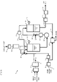
- FIG. 2 illustrates a configuration of the ozone water supply device 1 of this embodiment.
- a second gas dissolving nozzle 29 is provided on the liquid supply line 3 and the discharge line 22 from the second gas-liquid separator 16 is connected to the second gas dissolving nozzle 29.
- the second gas dissolving nozzle 29 dissolves undissolved excess ozone gas discharged from the second gas-liquid separator 16 in pure water being supplied to the liquid supply line 3.
- the first gas-liquid separator 8 is supplied with ozone water from the liquid supply line 3.
- the ozone water from the gas dissolving nozzle 29 may be introduced from an upper portion of the first gas-liquid separator 8.
- the ozone water from the gas dissolving nozzle 29 may also be introduced from a lower portion of the first gas-liquid separator 8. In that case, the gas dissolving nozzle 29 is preferably disposed in a lower portion of the first gas-liquid separator 8.
- pressure control is also performed with the pressure regulating valve 11 on the circulating supply line 9 so that the value of the pressure sensor 26 on the ozone water supply line 24 is constant as with the first embodiment.
- Flow rate control is also performed with the pressure booster pump 18 on the intermediate line 17 so that the value of the flow sensor 25 on the ozone water supply line 24 is the same as the value of the flow sensor 19 on the intermediate line 17.
- flow rate control is performed with the flow regulating valve 6 on the liquid supply line 3 so that the difference between the value of the flow sensor 25 on the ozone water supply line 24 and the value of the flow sensor 10 on the circulating supply line 9 is the same as the value of the flow sensor 7 on the liquid supply line 3.
- gas flow rate in the gas supply line 2 is adjusted with the adjuster 4 based on the value of the ozone water concentration meter 28 on the delivery line 27, and the gas concentration in the gas supply line 2 is adjusted with the ozonizer 5 (electric power discharged at the ozonizer 5 is adjusted), thus controlling the gas flow rate and the gas concentration (the feed rate of ozone gas) .
- the ozone water supply device 1 of the second embodiment as described above also provides similar effects to the first embodiment.
- this embodiment can recycle undissolved excess ozone gas discharged from the second gas-liquid separator 16, further reducing the usage of ozone gas as a material of ozone water. Further, this embodiment enables a further higher concentration of ozone water than in the first embodiment.
- the ozone water supply device 1 according to a third embodiment of the present invention is described.
- differences of the ozone water supply device 1 of the third embodiment from the second embodiment are focused.
- the configuration and operation of the third embodiment are similar to the second embodiment.
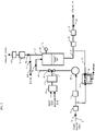
- FIG. 3 illustrates a configuration of the ozone water supply device 1 of this embodiment.
- this embodiment does not include the circulating supply line 9 to circulate unused ozone water at the use point and supply it to the first gas-liquid separator 8.
- the pressure in the first gas-liquid separator 8 can be made high compared with the first and second embodiments, allowing a higher concentration of ozone water.
- pressure control is performed by the pressure regulating valve 11 of the circulating supply line 9 so that the value of the flow sensor 25 or the pressure sensor 26 on the ozone water supply line 24 is constant. Further, flow rate control is performed with the pressure booster pump 18 on the intermediate line 17 so that the value of flow sensor 25 on the ozone water supply line 24 is the same as the value of the flow sensor 19 on the intermediate line 17, and flow rate control is further performed with the flow regulating valve 6 on the liquid supply line 3 so that the value of the flow sensor 7 on the liquid supply line 3 is the same as well.
- gas flow rate in the gas supply line 2 is adjusted with the adjuster 4 based on the value of the ozone water concentration meter 28 on the delivery line 27, and the gas concentration in the gas supply line 2 is adjusted with the ozonizer 5 (electric power discharged at the ozonizer 5 is adjusted), thus controlling the gas flow rate and the gas concentration (the feed rate of ozone gas) .
- the ozone water supply device 1 of the third embodiment as described above also provides similar effects to the second embodiment.
- this embodiment does not allow recycling of unused ozone water at the use point since the circulating supply line 9 is not present, further higher concentration is possible than in the second embodiment.
- the ozone water supply device 1 according to a fourth embodiment of the present invention is discussed.
- differences of the ozone water supply device 1 of the fourth embodiment from the first embodiment are focused.
- the configuration and operation of the fourth embodiment are similar to the first embodiment.
- FIG. 4 illustrates a configuration of the ozone water supply device 1 of this embodiment.
- the liquid supply line 3 is not connected with the first gas-liquid separator 8 but with the pressure booster pump 18. Further, the liquid supply line 3 meets an ozone water supply line 30 on which ozone water from the first gas-liquid separator 8 is supplied. Further, the discharge line 22 of the second gas-liquid separator 16 is not connected with the exhaust line 13 but with the circulating supply line 9.
- the ozone water supply device 1 of the fourth embodiment as described above also provides similar effects to the first embodiment.
- the ozone water supply device 1 can have an internal cleaning function for the gas-liquid separators 8, 16.
- examples (variations) of the ozone water supply device 1 having a cleaning function for the gas-liquid separators is described.
- FIG. 5 shows a configuration of a variation (Variation 1) of the ozone water supply device 1 of the first embodiment.
- a valve 31 is provided on the liquid supply line 3, on which pure water is supplied, and a valve 32 is provided on the ozone water supply line 24, which supplies ozone water to the use point.
- a valve 33 is provided on the circulating supply line 9, which returns unused ozone water at the use point to the ozone water supply device 1.
- a valve 34 is provided on the exhaust line 13 from the first gas-liquid separator 8 to an exhaust port, and a valve 35 is provided on a drain line 130 branching from the exhaust line 13.
- the exhaust line 13 further includes a valve 36 having an opening adjusting function.
- open and close control is performed such that the valve 32, the valve 33, the valve 34 and the valve 36 are opened and the valve 35 is closed.
- the valve 31 is controlled for opening and closing according to the level in the first gas-liquid separator 8 as detected by the level sensor 12. Specifically, open and close control is performed such that the valve 31 is closed when the level in the first gas-liquid separator 8 is high and the valve 31 is opened when the level in the first gas-liquid separator 8 is low.
- valve 31 is opened and the degree of opening of the valve 36 is reduced, thus causing gas in the first gas-liquid separator 8 to gradually escape and the first gas-liquid separator 8 to be filled with pure water. Since the valve 32 is closed and the valve 40 within the ozone water concentration meter 28 is also closed, the level in the second gas-liquid separator 16 gradually rises, until the second gas-liquid separator 16 is filled with pure water. In this manner, insides of the first gas-liquid separator 8 and the second gas-liquid separator 16 can be cleaned with pure water.
- ozone water can be supplied to the use point and also the insides of the first gas-liquid separator 8 and the second gas-liquid separator 16 can be cleaned with pure water.
- Variation 2 a variation of the ozone water supply device 1 according to the second embodiment is described.
- differences of Variation 2 from Variation 1 are focused.
- the configuration and operation of Variation 2 are similar to Variation 1.
- FIG. 6 shows a configuration of the ozone water supply device 1 in Variation 2. Pure water from the second gas-liquid separator 16 is sent from the discharge line 22 to the first gas-liquid separator 8 via the nozzle 29. The valve 36 is opened and pure water from the first gas-liquid separator 8 is discharged to the drain from the drain line 130 branching from the exhaust line 13.
- ozone water can also be supplied to the use point and the insides of the first gas-liquid separator 8 and the second gas-liquid separator 16 can be cleaned with pure water by performing open and close control of the valves 31 to 36 as with Variation 1.
- Variation 3 a variation of the ozone water supply device 1 according to the third embodiment is described.
- differences of Variation 3 from Variation 1 are focused.
- the configuration and operation of Variation 3 are similar to Variation 1.
- FIG. 7 shows a configuration of the ozone water supply device 1 in Variation 3. Since the ozone water supply device 1 of Variation 3 does not include the circulating supply line 9, it does not include the valve 33 provided on the circulating supply line 9 either. Pure water from the second gas-liquid separator 16 is sent from the discharge line 22 to the first gas-liquid separator 8 via the nozzle 29. The valve 36 is opened and pure water from the first gas-liquid separator 8 is discharged to the drain from the drain line 130 branching from the exhaust line 13.
- ozone water can also be supplied to the use point and the insides of the first gas-liquid separator 8 and the second gas-liquid separator 16 can be cleaned with pure water by performing open and close control of the valves 31, 32, 34, 35, 36 as with Variation 1.
- Variation 4 a variation of the ozone water supply device 1 according to the fourth embodiment is described.
- differences of Variation 4 from Variation 1 are focused.
- the configuration and operation of Variation 4 are similar to Variation 1.
- FIG. 8 shows a configuration of the ozone water supply device 1 in Variation 4.
- the valve 36 with an opening adjusting function is not provided on the exhaust line 13. Rather, in Variation 4, a valve 37 is provided on the ozone water supply line 30 from the first gas-liquid separator 8.
- open and close control is performed such that the valve 32, valve 33, the valve 34 and the valve 37 are opened and the valve 35 is closed.
- the valve 31 is controlled for opening and closing according to the level in the first gas-liquid separator 8 as detected by the level sensor 12. Specifically, open and close control is performed such that the valve 31 is closed when the level in the first gas-liquid separator 8 is high and the valve 31 is opened when the level in the first gas-liquid separator 8 is low.
- the level in the second gas-liquid separator 16 gradually rises since the valve 32 and the valve 37 are closed, until the second gas-liquid separator 16 is filled with pure water. In this manner, the inside of the second gas-liquid separator 16 can be cleaned with pure water.
- valve 34 Since in this case the valve 34 is closed and the valve 35 is opened, pure water from the first gas-liquid separator 8 is discharged to the drain from the drain line 130 branching from the exhaust line 13.
- ozone water can also be supplied to the use point and the insides of the first gas-liquid separator 8 and the second gas-liquid separator 16 can be cleaned with pure water by performing open and close control of the valves 31 to 35 and 37 as described above.
- FIG. 9 shows another example of the ozone water supply device 1.
- the first gas-liquid separator 8 is not provided, while a valve 39 is provided on a supply line 38 which supplies ozone water generated via the gas dissolving nozzle 20 to the second gas-liquid separator 16. Further, the exhaust line 13 is provided at the second gas-liquid separator 16.
- open and close control is performed so that the valve 32, the valve 34 and the valve 39 are opened and the valve 35 is closed.
- the valve 31 is controlled for opening and closing according to the level in the second gas-liquid separator 16 as detected by the level sensor 21. Specifically, open and close control is performed such that the valve 31 is closed when the level in the second gas-liquid separator 16 is high and the valve 31 is opened when the level in the second gas-liquid separator 16 is low.
- the level in the second gas-liquid separator 16 gradually rises since the valve 32 is closed, until the second gas-liquid separator 16 is filled with pure water. In this manner, the inside of the second gas-liquid separator 16 can be cleaned with pure water.
- valve 34 Since in this case the valve 34 is closed and the valve 35 is opened, pure water from the second gas-liquid separator 16 is discharged to the drain from the drain line 130 branching from the exhaust line 13.
- ozone water can also be supplied to the use point and the inside of the second gas-liquid separator 16 can be cleaned with pure water by performing open and close control of the valves 31, 32, 34, 35, 39 as described above.
- the gas solution supply devices according to the present invention has the effects of enabling a high concentration of gas solution and suppressing fluctuations in the delivery pressure of gas solution, and can be advantageously used for production of ozone water and the like.
Landscapes
- Chemical & Material Sciences (AREA)
- Chemical Kinetics & Catalysis (AREA)
- Organic Chemistry (AREA)
- Health & Medical Sciences (AREA)
- General Health & Medical Sciences (AREA)
- Toxicology (AREA)
- Inorganic Chemistry (AREA)
- Cleaning Or Drying Semiconductors (AREA)
- Oxygen, Ozone, And Oxides In General (AREA)
Abstract
Description
- The present invention relates to a gas solution supply device for supplying gas solution, and in particular to a technique for achieving a high concentration of gas solution.
- Ozone water has been used for cleaning electronic components such as semiconductor devices and liquid crystal. Ozone water is produced by dissolving ozone gas in ultrapure water and then supplied to a use point (such as a semiconductor device factory and an electronic component factory).
- In a conventional ozone water producing device, ozone water produced by dissolving ozone gas in ultrapure water is stored in a gas-liquid separator and the ozone water is delivered from the gas-liquid separator to the use point by a pump located at a stage subsequent to the gas-liquid separator (downstream thereof), for example (see
Japanese Patent Laid-Open No. 2019-155221 - However, since a conventional device has only one gas-liquid separator and a pump (a pump for delivering ozone water to the use point) is provided subsequent to the gas-liquid separator, a pressure in the gas-liquid separator is difficult to increase, making it difficult to achieve a high concentration of ozone water. Where the pump is an air-driven pump, it is also difficult to suppress fluctuations in delivery pressure of ozone water due to influence of pulsation of the pump.
- An object of the present invention, which has been made in view of these challenges, is to provide a gas solution supply device that can achieve a high concentration of gas solution and can suppress fluctuations in the delivery pressure of gas solution.
- A gas solution supply device according to the present invention includes: a first gas-liquid separator in which gas solution is stored; a second gas-liquid separator which is provided at a stage subsequent to the first gas-liquid separator and in which gas solution to be supplied to a use point is stored; an intermediate line provided between the first gas-liquid separator and the second gas-liquid separator; a pressure booster pump that is provided on the intermediate line and increases a pressure of gas solution being supplied from the first gas-liquid separator to the second gas-liquid separator; a gas supply line that supplies gas as a material of the gas solution; and a gas dissolving unit that is provided on the intermediate line and dissolves the gas supplied from the gas supply line in the gas solution supplied from the first gas-liquid separator.
- In this arrangement, the pressure booster pump is provided at a stage preceding the second gas-liquid separator, so that the pressure in the second gas-liquid separator can be increased and a high concentration of gas solution is possible. In addition, providing the second gas-liquid separator at a stage subsequent to the pressure booster pump results in damper effect, making it possible to suppress fluctuations in delivery pressure of gas solution being supplied from the second gas-liquid separator to the use point.
- In the gas solution supply device of the present invention, the first gas-liquid separator may include a circulating supply line for circulating and supplying unused gas solution at the use point.
- With this arrangement, unused gas solution at the use point can be recycled and usage of gas as a material of gas solution can be reduced. Since in this case the first gas-liquid separator, to which unused gas solution at the use point is supplied, is provided at a stage preceding the pressure booster pump, there is no need for a pump to increase the pressure of the unused gas solution.
- In the gas solution supply device of the present invention, the first gas-liquid separator may include a liquid supply line through which liquid as a material of the gas solution is supplied, and the liquid supply line may include a second gas dissolving unit that dissolves undissolved excess gas discharged from the second gas-liquid separator in the liquid as a material of the gas solution.
- With this arrangement, undissolved excess gas discharged from the second gas-liquid separator can be recycled and usage of gas as a material of gas solution can be reduced.
- The gas solution supply device of the present invention may include: a first valve provided on a liquid supply line that supplies liquid as a material of the gas solution; a second valve provided on a gas solution supply line that supplies the gas solution to the use point; a third valve provided on an exhaust line from the first gas-liquid separator to an exhaust port; a fourth valve provided on a drain line branching from the exhaust line; and a control unit that performs open and close control of the first valve, the second valve, the third valve, and the fourth valve. The control unit may be configured to: when the gas solution is to be supplied to the use point, perform control to open the first valve, the second valve and the third valve and close the fourth valve, and when the first gas-liquid separator and the second gas-liquid separator are to be cleaned, perform control to close the second valve and the third valve and open the first valve and the fourth valve.
- With this arrangement, gas solution can be supplied to the use point by opening the first, the second and the third valves and closing the fourth valve, while the first gas-liquid separator and the second gas-liquid separator can be cleaned by closing the second and the third valves and opening the first and the fourth valves.
- A method according to the present invention is a method for execution in a gas solution supply device, the gas solution supply device including: a first gas-liquid separator in which gas solution is stored; a second gas-liquid separator which is provided at a stage subsequent to the first gas-liquid separator and in which gas solution to be supplied to a use point is stored; an intermediate line provided between the first gas-liquid separator and the second gas-liquid separator; and a pressure booster pump that is provided on the intermediate line and increases a pressure of gas solution being supplied from the first gas-liquid separator to the second gas-liquid separator. The method includes the steps of supplying gas as a material of the gas solution to the intermediate line, and dissolving the supplied gas in the gas solution supplied from the first gas-liquid separator.
- This method can also increase the pressure in the second gas-liquid separator and enable a high concentration of gas solution because the pressure booster pump is provided at a stage preceding the second gas-liquid separator as with the device above. Further, providing the second gas-liquid separator at a stage subsequent to the pressure booster pump results in damper effect, making it possible to suppress fluctuations in delivery pressure of gas solution being supplied from the second gas-liquid separator to the use point.
- In the method of the present invention, the gas solution supply device may include: a first valve provided on a liquid supply line that supplies liquid as a material of the gas solution; a second valve provided on a gas solution supply line that supplies the gas solution to the use point; a third valve provided on an exhaust line from the first gas-liquid separator to an exhaust port; and a fourth valve provided on a drain line branching from the exhaust line. The method may include: when the gas solution is to be supplied to the use point, opening the first valve, the second valve and the third valve and closing the fourth valve, and when the first gas-liquid separator and the second gas-liquid separator are to be cleaned, closing the second valve and the third valve and opening the first valve and the fourth valve.
- According to this method, gas solution can be supplied to the use point by opening the first, the second and the third valves and closing the fourth valve, while the first gas-liquid separator and the second gas-liquid separator can be cleaned by closing the second and the third valves and opening the first and the fourth valves.
- The present invention can achieve a high concentration of gas solution and can suppress fluctuations in the delivery pressure of gas solution.
-
-
FIG. 1 illustrates a configuration of a gas solution supply device (ozone water supply device) in a first embodiment of the present invention; -
FIG. 2 illustrates a configuration of the gas solution supply device (ozone water supply device) in a second embodiment of the present invention; -
FIG. 3 illustrates a configuration of the gas solution supply device (ozone water supply device) in a third embodiment of the present invention; -
FIG. 4 illustrates a configuration of the gas solution supply device (ozone water supply device) in a fourth embodiment of the present invention; -
FIG. 5 shows a configuration of a variation of the gas solution supply device (ozone water supply device) of the first embodiment; -
FIG. 6 shows a configuration of a variation of the gas solution supply device (ozone water supply device) of the second embodiment; -
FIG. 7 shows a configuration of a variation of the gas solution supply device (ozone water supply device) of the third embodiment; -
FIG. 8 shows a configuration of a variation of the gas solution supply device (ozone water supply device) of the fourth embodiment; and -
FIG. 9 shows another example of the gas solution supply device (ozone water supply device). - Gas solution supply devices according to embodiments of the present invention are now described with reference to the drawings. The embodiments herein illustrate ozone water supply devices that are used for production of ozone water and the like.
- Configuration of an ozone water supply device according to a first embodiment of the present invention is described with reference to a drawing.
FIG. 1 illustrates a configuration of the ozone water supply device of this embodiment. As shown inFIG. 1 , an ozonewater supply device 1 includes agas supply line 2 through which ozone gas as a material of ozone water is supplied and aliquid supply line 3 through which pure water (DIW) as a material of ozone water is supplied. - The
gas supply line 2 is supplied with a first gas (e.g., oxygen gas) and a second gas (e.g., carbon dioxide gas, nitrogen gas, or mixed gas of carbon dioxide gas and nitrogen gas) as materials of ozone gas. Thegas supply line 2 includes a gasflow rate adjuster 4 and anozonizer 5. The gas flow rate adjuster 4 adjusts a flow rate of the first gas and that of the second gas. Theozonizer 5 generates ozone gas from the material gas (mixed gas of the first gas and the second gas) by electric discharge. - The
liquid supply line 3 is supplied with pure water, with the flow rate of the pure water being adjusted by aflow regulating valve 6 and the flow rate of the pure water being measured by aflow sensor 7. Theliquid supply line 3 is connected with a first gas-liquid separator 8. The first gas-liquid separator 8 is connected with a circulatingsupply line 9, which circulates and supplies unused ozone water at a use point. - The circulating
supply line 9 includes aflow sensor 10 for measuring the flow rate of unused ozone water at the use point and apressure regulating valve 11 for adjusting a pressure of the unused ozone water at the use point. - The first gas-
liquid separator 8 stores unused ozone water and includes alevel sensor 12 for measuring a level of the ozone water. The first gas-liquid separator 8 includes anexhaust line 13 for discharging undissolved ozone gas. Theexhaust line 13 includes anozone gas decomposer 14 for decomposing ozone gas and apressure regulating valve 15 for adjusting the pressure of ozone gas being exhausted. - A second gas-
liquid separator 16 in which ozone water to be supplied to the use point is stored is provided at a stage subsequent to (downstream of) the first gas-liquid separator 8, the first gas-liquid separator 8 and the second gas-liquid separator 16 being connected by anintermediate line 17. - The
intermediate line 17 includes apressure booster pump 18 that increases the pressure of ozone water being supplied from the first gas-liquid separator 8 to the second gas-liquid separator 16, aflow sensor 19 that measures the flow rate of ozone water being supplied to the second gas-liquid separator 16, and agas dissolving nozzle 20 that dissolves the ozone gas supplied from thegas supply line 2 in the ozone water supplied from the first gas-liquid separator 8. The ozone water from thegas dissolving nozzle 20 may be introduced from an upper portion of the second gas-liquid separator 16. The ozone water from thegas dissolving nozzle 20 may also be introduced from a lower portion of the second gas-liquid separator 16. In that case, thegas dissolving nozzle 20 is preferably disposed in a lower portion of the second gas-liquid separator 16. - The
pressure booster pump 18 can be a centrifugal pump, a bellows pump, or a diaphragm pump, for example. A portion of thepressure booster pump 18 that makes contact with ozone water and/or ozone gas is made of a material resistant to ozone water and ozone gas (e.g., fluorine resin). - The
gas dissolving nozzle 20 can be an ejector or an aspirator, for example. An ejector and an aspirator can dissolve ozone gas in pure water by making use of Venturi effect. When an ejector or an aspirator is used, regular replacement would be unnecessary and diffusion rate would be also improved compared to an ozone dissolver using hollow fiber membrane. Thegas dissolving nozzle 20 is preferably provided subsequent to thepressure booster pump 18. If thegas dissolving nozzle 20 is provided at a stage preceding thepressure booster pump 18, gas-liquid mixture would be supplied to thepressure booster pump 18, resulting in lower pumping and pressure boosting performances of thepressure booster pump 18 and lower flow rate and pressure of ozone water being supplied. - The second gas-
liquid separator 16 has alevel sensor 21 for measuring the level of ozone water. The second gas-liquid separator 16 also includes adischarge line 22 for discharging undissolved ozone gas. Thedischarge line 22 includes apressure regulating valve 23 for adjusting the pressure of ozone gas being discharged from the second gas-liquid separator 16. In this embodiment, thedischarge line 22 from the second gas-liquid separator 16 is connected with theexhaust line 13 from the first gas-liquid separator 8. - The second gas-
liquid separator 16 includes an ozonewater supply line 24 for supplying ozone water to the use point. The ozonewater supply line 24 includes aflow sensor 25 for measuring the flow rate of the ozone water being supplied to the use point and apressure sensor 26 for measuring the pressure of the ozone water being supplied to the use point. - The ozone
water supply line 24 and theliquid supply line 3 each have adelivery line 27 branching from the ozonewater supply line 24 and theliquid supply line 3, respectively, thedelivery line 27 being connected with the circulatingsupply line 9. Thedelivery line 27 includes an ozonewater concentration meter 28 for measuring a concentration of ozone water. The ozonewater concentration meter 28 has a switching valve such that both a zero point of DIW can be measured and the concentration of ozone water can be checked. - With the ozone
water supply device 1 of this embodiment, pressure control is performed by thepressure regulating valve 11 of the circulatingsupply line 9 so that a value of thepressure sensor 26 on the ozonewater supply line 24 is constant. Pressure control is also performed with thepressure booster pump 18 on theintermediate line 17 so that the value of theflow sensor 25 on the ozonewater supply line 24 is the same as the value of theflow sensor 19 on theintermediate line 17. Alternatively, flow rate control is performed with theflow regulating valve 6 on theliquid supply line 3 so that the difference between the value of theflow sensor 25 on the ozonewater supply line 24 and the value of theflow sensor 10 on the circulatingsupply line 9 is the same as the value of theflow sensor 7 on theliquid supply line 3. Further, gas flow rate in thegas supply line 2 is adjusted with theadjuster 4 based on the value of the ozonewater concentration meter 28 on thedelivery line 27, and the gas concentration in thegas supply line 2 is adjusted with the ozonizer 5 (electric power discharged at theozonizer 5 is adjusted), thus controlling the gas flow rate and the gas concentration (feed rate of ozone gas). - Since the ozone
water supply device 1 of the first embodiment has thepressure booster pump 18 at a stage preceding the second gas-liquid separator 16 as described above, the pressure in the second gas-liquid separator 16 can be increased, enabling a high concentration of ozone water. Further, providing the second gas-liquid separator 16 at a stage subsequent to thepressure booster pump 18 results in damper effect, making it possible to suppress fluctuations in the delivery pressure of ozone water being supplied from the second gas-liquid separator 16 to the use point. - In addition, this embodiment can recycle unused ozone water at the use point and reduce usage of ozone gas and DIW as materials of ozone water. Since in this case the first gas-
liquid separator 8, to which unused ozone water at the use point is supplied, is provided at a stage preceding thepressure booster pump 18, there is no need for a pump to increase the pressure of the unused ozone water. - Next, the ozone
water supply device 1 according to a second embodiment of the present invention is discussed. Here, differences of the ozonewater supply device 1 of the second embodiment from the first embodiment are focused. Unless otherwise noted, the configuration and operation of the second embodiment are similar to the first embodiment. -
FIG. 2 illustrates a configuration of the ozonewater supply device 1 of this embodiment. As shown inFIG. 2 , in the second embodiment, a secondgas dissolving nozzle 29 is provided on theliquid supply line 3 and thedischarge line 22 from the second gas-liquid separator 16 is connected to the secondgas dissolving nozzle 29. The secondgas dissolving nozzle 29 dissolves undissolved excess ozone gas discharged from the second gas-liquid separator 16 in pure water being supplied to theliquid supply line 3. The first gas-liquid separator 8 is supplied with ozone water from theliquid supply line 3. The ozone water from thegas dissolving nozzle 29 may be introduced from an upper portion of the first gas-liquid separator 8. The ozone water from thegas dissolving nozzle 29 may also be introduced from a lower portion of the first gas-liquid separator 8. In that case, thegas dissolving nozzle 29 is preferably disposed in a lower portion of the first gas-liquid separator 8. - In the ozone
water supply device 1 of this embodiment, pressure control is also performed with thepressure regulating valve 11 on the circulatingsupply line 9 so that the value of thepressure sensor 26 on the ozonewater supply line 24 is constant as with the first embodiment. Flow rate control is also performed with thepressure booster pump 18 on theintermediate line 17 so that the value of theflow sensor 25 on the ozonewater supply line 24 is the same as the value of theflow sensor 19 on theintermediate line 17. Alternatively, flow rate control is performed with theflow regulating valve 6 on theliquid supply line 3 so that the difference between the value of theflow sensor 25 on the ozonewater supply line 24 and the value of theflow sensor 10 on the circulatingsupply line 9 is the same as the value of theflow sensor 7 on theliquid supply line 3. Further, gas flow rate in thegas supply line 2 is adjusted with theadjuster 4 based on the value of the ozonewater concentration meter 28 on thedelivery line 27, and the gas concentration in thegas supply line 2 is adjusted with the ozonizer 5 (electric power discharged at theozonizer 5 is adjusted), thus controlling the gas flow rate and the gas concentration (the feed rate of ozone gas) . - The ozone
water supply device 1 of the second embodiment as described above also provides similar effects to the first embodiment. - Besides, this embodiment can recycle undissolved excess ozone gas discharged from the second gas-
liquid separator 16, further reducing the usage of ozone gas as a material of ozone water. Further, this embodiment enables a further higher concentration of ozone water than in the first embodiment. - Next, the ozone
water supply device 1 according to a third embodiment of the present invention is described. Here, differences of the ozonewater supply device 1 of the third embodiment from the second embodiment are focused. Unless otherwise noted, the configuration and operation of the third embodiment are similar to the second embodiment. -
FIG. 3 illustrates a configuration of the ozonewater supply device 1 of this embodiment. As shown inFIG. 3 , this embodiment does not include the circulatingsupply line 9 to circulate unused ozone water at the use point and supply it to the first gas-liquid separator 8. Thus, the pressure in the first gas-liquid separator 8 can be made high compared with the first and second embodiments, allowing a higher concentration of ozone water. - With the ozone
water supply device 1 of this embodiment, pressure control is performed by thepressure regulating valve 11 of the circulatingsupply line 9 so that the value of theflow sensor 25 or thepressure sensor 26 on the ozonewater supply line 24 is constant. Further, flow rate control is performed with thepressure booster pump 18 on theintermediate line 17 so that the value offlow sensor 25 on the ozonewater supply line 24 is the same as the value of theflow sensor 19 on theintermediate line 17, and flow rate control is further performed with theflow regulating valve 6 on theliquid supply line 3 so that the value of theflow sensor 7 on theliquid supply line 3 is the same as well. Moreover, gas flow rate in thegas supply line 2 is adjusted with theadjuster 4 based on the value of the ozonewater concentration meter 28 on thedelivery line 27, and the gas concentration in thegas supply line 2 is adjusted with the ozonizer 5 (electric power discharged at theozonizer 5 is adjusted), thus controlling the gas flow rate and the gas concentration (the feed rate of ozone gas) . - The ozone
water supply device 1 of the third embodiment as described above also provides similar effects to the second embodiment. - Although this embodiment does not allow recycling of unused ozone water at the use point since the circulating
supply line 9 is not present, further higher concentration is possible than in the second embodiment. - Next, the ozone
water supply device 1 according to a fourth embodiment of the present invention is discussed. Here, differences of the ozonewater supply device 1 of the fourth embodiment from the first embodiment are focused. Unless otherwise noted, the configuration and operation of the fourth embodiment are similar to the first embodiment. -
FIG. 4 illustrates a configuration of the ozonewater supply device 1 of this embodiment. As shown inFIG. 4 , in this embodiment, theliquid supply line 3 is not connected with the first gas-liquid separator 8 but with thepressure booster pump 18. Further, theliquid supply line 3 meets an ozonewater supply line 30 on which ozone water from the first gas-liquid separator 8 is supplied. Further, thedischarge line 22 of the second gas-liquid separator 16 is not connected with theexhaust line 13 but with the circulatingsupply line 9. - The ozone
water supply device 1 of the fourth embodiment as described above also provides similar effects to the first embodiment. - The ozone
water supply device 1 can have an internal cleaning function for the gas-liquid separators water supply device 1 having a cleaning function for the gas-liquid separators is described. -
FIG. 5 shows a configuration of a variation (Variation 1) of the ozonewater supply device 1 of the first embodiment. As shown inFIG. 5 , inVariation 1, avalve 31 is provided on theliquid supply line 3, on which pure water is supplied, and avalve 32 is provided on the ozonewater supply line 24, which supplies ozone water to the use point. Avalve 33 is provided on the circulatingsupply line 9, which returns unused ozone water at the use point to the ozonewater supply device 1. Further, avalve 34 is provided on theexhaust line 13 from the first gas-liquid separator 8 to an exhaust port, and avalve 35 is provided on adrain line 130 branching from theexhaust line 13. Theexhaust line 13 further includes avalve 36 having an opening adjusting function. Thesevalves 31 to 36 can be controlled for opening and closing by a control unit (not shown) provided in the ozonewater supply device 1. - In
Variation 1, when ozone water is to be supplied to the use point, open and close control is performed such that thevalve 32, thevalve 33, thevalve 34 and thevalve 36 are opened and thevalve 35 is closed. Thevalve 31 is controlled for opening and closing according to the level in the first gas-liquid separator 8 as detected by thelevel sensor 12. Specifically, open and close control is performed such that thevalve 31 is closed when the level in the first gas-liquid separator 8 is high and thevalve 31 is opened when the level in the first gas-liquid separator 8 is low. - In contrast, when supply of ozone water to the use point is stopped and the gas-
liquid separators valve 31 and thevalve 35 are opened, the degree of opening of thevalve 36 is reduced, and thevalve 32, thevalve 33 and thevalve 34 are closed. In doing so, thelevel sensors gas supply line 2 is also stopped. - Once pure water is supplied from the
liquid supply line 3, thevalve 31 is opened and the degree of opening of thevalve 36 is reduced, thus causing gas in the first gas-liquid separator 8 to gradually escape and the first gas-liquid separator 8 to be filled with pure water. Since thevalve 32 is closed and thevalve 40 within the ozonewater concentration meter 28 is also closed, the level in the second gas-liquid separator 16 gradually rises, until the second gas-liquid separator 16 is filled with pure water. In this manner, insides of the first gas-liquid separator 8 and the second gas-liquid separator 16 can be cleaned with pure water. - With the
valve 32 being closed, pure water from the second gas-liquid separator 16 is sent from thedischarge line 22 to theexhaust line 13. Then, the pure water is discharged to a drain from thedrain line 130 branching from theexhaust line 13. - In this case, as the
valve 34 is closed and thevalve 35 is opened, pure water from the first gas-liquid separator 8 is discharged to the drain from thedrain line 130 branching from theexhaust line 13. In a case where an ozone decomposer (not shown) is provided on thedrain line 130, the insides of the gas-liquid separators - According to
Variation 1, by performing open and close control of thevalves 31 to 36 as described above, ozone water can be supplied to the use point and also the insides of the first gas-liquid separator 8 and the second gas-liquid separator 16 can be cleaned with pure water. - Next, a variation (Variation 2) of the ozone
water supply device 1 according to the second embodiment is described. Here, differences ofVariation 2 fromVariation 1 are focused. Unless otherwise noted, the configuration and operation ofVariation 2 are similar toVariation 1. -
FIG. 6 shows a configuration of the ozonewater supply device 1 inVariation 2. Pure water from the second gas-liquid separator 16 is sent from thedischarge line 22 to the first gas-liquid separator 8 via thenozzle 29. Thevalve 36 is opened and pure water from the first gas-liquid separator 8 is discharged to the drain from thedrain line 130 branching from theexhaust line 13. - In
Variation 2 as described above, ozone water can also be supplied to the use point and the insides of the first gas-liquid separator 8 and the second gas-liquid separator 16 can be cleaned with pure water by performing open and close control of thevalves 31 to 36 as withVariation 1. - Next, a variation (Variation 3) of the ozone
water supply device 1 according to the third embodiment is described. Here, differences ofVariation 3 fromVariation 1 are focused. Unless otherwise noted, the configuration and operation ofVariation 3 are similar toVariation 1. -
FIG. 7 shows a configuration of the ozonewater supply device 1 inVariation 3. Since the ozonewater supply device 1 ofVariation 3 does not include the circulatingsupply line 9, it does not include thevalve 33 provided on the circulatingsupply line 9 either. Pure water from the second gas-liquid separator 16 is sent from thedischarge line 22 to the first gas-liquid separator 8 via thenozzle 29. Thevalve 36 is opened and pure water from the first gas-liquid separator 8 is discharged to the drain from thedrain line 130 branching from theexhaust line 13. - In
Variation 3 as described above, ozone water can also be supplied to the use point and the insides of the first gas-liquid separator 8 and the second gas-liquid separator 16 can be cleaned with pure water by performing open and close control of thevalves Variation 1. - Next, a variation (Variation 4) of the ozone
water supply device 1 according to the fourth embodiment is described. Here, differences ofVariation 4 fromVariation 1 are focused. Unless otherwise noted, the configuration and operation ofVariation 4 are similar toVariation 1. -
FIG. 8 shows a configuration of the ozonewater supply device 1 inVariation 4. As shown inFIG. 8 , inVariation 4, thevalve 36 with an opening adjusting function is not provided on theexhaust line 13. Rather, inVariation 4, avalve 37 is provided on the ozonewater supply line 30 from the first gas-liquid separator 8. - In
Variation 4, when ozone water is to be supplied to the use point, open and close control is performed such that thevalve 32,valve 33, thevalve 34 and thevalve 37 are opened and thevalve 35 is closed. Thevalve 31 is controlled for opening and closing according to the level in the first gas-liquid separator 8 as detected by thelevel sensor 12. Specifically, open and close control is performed such that thevalve 31 is closed when the level in the first gas-liquid separator 8 is high and thevalve 31 is opened when the level in the first gas-liquid separator 8 is low. - In contrast, when supply of ozone water to the use point is stopped and the gas-
liquid separators valve 31 and thevalve 35 are opened and thevalve 32, thevalve 33, thevalve 34 and thevalve 37 are closed. In doing so, thelevel sensors gas supply line 2 is also stopped. - Once pure water is supplied from the
liquid supply line 3, the level in the second gas-liquid separator 16 gradually rises since thevalve 32 and thevalve 37 are closed, until the second gas-liquid separator 16 is filled with pure water. In this manner, the inside of the second gas-liquid separator 16 can be cleaned with pure water. - With the
valve 32 and thevalve 37 being closed, pure water from the second gas-liquid separator 16 is sent from thedischarge line 22 to the circulatingsupply line 9. Here, as thevalve 33 is closed, the pure water sent to the circulatingsupply line 9 is supplied to the first gas-liquid separator 8. Then, with thevalve 37 being closed, the level in the first gas-liquid separator 8 also gradually rises, until the first gas-liquid separator 8 is filled with pure water. In this manner, the inside of the first gas-liquid separator 8 can be cleaned with pure water. - Since in this case the
valve 34 is closed and thevalve 35 is opened, pure water from the first gas-liquid separator 8 is discharged to the drain from thedrain line 130 branching from theexhaust line 13. - In
Variation 4, ozone water can also be supplied to the use point and the insides of the first gas-liquid separator 8 and the second gas-liquid separator 16 can be cleaned with pure water by performing open and close control of thevalves 31 to 35 and 37 as described above. -
FIG. 9 shows another example of the ozonewater supply device 1. In the example ofFIG. 9 , the first gas-liquid separator 8 is not provided, while avalve 39 is provided on asupply line 38 which supplies ozone water generated via thegas dissolving nozzle 20 to the second gas-liquid separator 16. Further, theexhaust line 13 is provided at the second gas-liquid separator 16. - In the example of
FIG. 9 , when ozone water is to be supplied to the use point, open and close control is performed so that thevalve 32, thevalve 34 and thevalve 39 are opened and thevalve 35 is closed. Thevalve 31 is controlled for opening and closing according to the level in the second gas-liquid separator 16 as detected by thelevel sensor 21. Specifically, open and close control is performed such that thevalve 31 is closed when the level in the second gas-liquid separator 16 is high and thevalve 31 is opened when the level in the second gas-liquid separator 16 is low. - In contrast, when supply of ozone water to the use point is stopped and the second gas-
liquid separator 16 is to be cleaned, open and close control is performed such that thevalve 31, thevalve 35, and thevalve 39 are opened and thevalve 32 and thevalve 34 are closed. In doing so, thelevel sensor 21 is placed in a state where its high-level warning function is disabled. Further, supply of ozone gas from thegas supply line 2 is also stopped. - Once pure water is supplied from the
liquid supply line 3, the level in the second gas-liquid separator 16 gradually rises since thevalve 32 is closed, until the second gas-liquid separator 16 is filled with pure water. In this manner, the inside of the second gas-liquid separator 16 can be cleaned with pure water. - Since in this case the
valve 34 is closed and thevalve 35 is opened, pure water from the second gas-liquid separator 16 is discharged to the drain from thedrain line 130 branching from theexhaust line 13. - With the example of
FIG. 9 , ozone water can also be supplied to the use point and the inside of the second gas-liquid separator 16 can be cleaned with pure water by performing open and close control of thevalves - While the embodiments of the present invention have been described by way of example, the scope of the present invention is not limited to them and may be modified or altered according to an objective within the scope as defined by the claims.
- As shown above, the gas solution supply devices according to the present invention has the effects of enabling a high concentration of gas solution and suppressing fluctuations in the delivery pressure of gas solution, and can be advantageously used for production of ozone water and the like.
-
- 1
- ozone water supply device
- 2
- gas supply line
- 3
- liquid supply line
- 4
- gas flow rate adjuster
- 5
- ozonizer
- 6
- flow regulating valve
- 7
- flow sensor
- 8
- the first gas-liquid separator
- 9
- circulating supply line
- 10
- flow sensor
- 11
- pressure regulating valve
- 12
- level sensor
- 13
- exhaust line
- 14
- ozone gas decomposer
- 15
- pressure regulating valve
- 16
- the second gas-liquid separator
- 17
- intermediate line
- 18
- pressure booster pump
- 19
- flow sensor
- 20
- gas dissolving nozzle
- 21
- level sensor
- 22
- discharge line
- 23
- pressure regulating valve
- 24
- ozone water supply line
- 25
- flow sensor
- 26
- pressure sensor
- 27
- delivery line
- 28
- ozone water concentration meter
- 29
- the second gas dissolving nozzle
- 30
- ozone water supply line
- 31-37
- valves
- 38
- supply line
- 39
- valve
- 40
- valve
Claims (6)
- A gas solution supply device comprising:a first gas-liquid separator in which gas solution is stored;a second gas-liquid separator which is provided at a stage subsequent to the first gas-liquid separator and in which gas solution to be supplied to a use point is stored;an intermediate line provided between the first gas-liquid separator and the second gas-liquid separator;a pressure booster pump that is provided on the intermediate line and increases a pressure of gas solution being supplied from the first gas-liquid separator to the second gas-liquid separator;a gas supply line that supplies gas as a material of the gas solution; anda gas dissolving unit that is provided on the intermediate line and dissolves the gas supplied from the gas supply line in the gas solution supplied from the first gas-liquid separator.
- The gas solution supply device according to claim 1, wherein the first gas-liquid separator comprises a circulating supply line for circulating and supplying unused gas solution at the use point.
- The gas solution supply device according to claim 1 or 2, whereinthe first gas-liquid separator comprises a liquid supply line through which liquid as a material of the gas solution is supplied; andthe liquid supply line comprises a second gas dissolving unit that dissolves undissolved excess gas discharged from the second gas-liquid separator in the liquid as a material of the gas solution.
- The gas solution supply device according to any of claims 1 to 3, comprising:a first valve provided on a liquid supply line that supplies liquid as a material of the gas solution;a second valve provided on a gas solution supply line that supplies the gas solution to the use point;a third valve provided on an exhaust line from the first gas-liquid separator to an exhaust port;a fourth valve provided on a drain line branching from the exhaust line; anda control unit that performs open and close control of the first valve, the second valve, the third valve, and the fourth valve,wherein the control unit is configured to:when the gas solution is to be supplied to the use point, perform control to open the first valve, the second valve and the third valve and close the fourth valve, andwhen the first gas-liquid separator and the second gas-liquid separator are to be cleaned, perform control to close the second valve and the third valve and open the first valve and the fourth valve.
- A method for execution in a gas solution supply device, the gas solution supply device comprising:a first gas-liquid separator in which gas solution is stored;a second gas-liquid separator which is provided at a stage subsequent to the first gas-liquid separator and in which gas solution to be supplied to a use point is stored;an intermediate line provided between the first gas-liquid separator and the second gas-liquid separator;a pressure booster pump that is provided on the intermediate line and increases a pressure of gas solution being supplied from the first gas-liquid separator to the second gas-liquid separator, andthe method comprising the steps of:supplying gas as a material of the gas solution to the intermediate line; anddissolving the supplied gas in the gas solution supplied from the first gas-liquid separator.
- The method according to claim 5, wherein the gas solution supply device comprises:a first valve provided on a liquid supply line that supplies liquid as a material of the gas solution;a second valve provided on a gas solution supply line that supplies the gas solution to the use point;a third valve provided on an exhaust line from the first gas-liquid separator to an exhaust port; anda fourth valve provided on a drain line branching from the exhaust line,the method comprising:when the gas solution is to be supplied to the use point, opening the first valve, the second valve and the third valve and closing the fourth valve, andwhen the first gas-liquid separator and the second gas-liquid separator are to be cleaned, closing the second valve and the third valve and opening the first valve and the fourth valve.
Applications Claiming Priority (2)
| Application Number | Priority Date | Filing Date | Title |
|---|---|---|---|
| JP2020167237 | 2020-10-01 | ||
| JP2021092452A JP7550720B2 (en) | 2020-10-01 | 2021-06-01 | Gas dissolving liquid supply device |
Publications (2)
| Publication Number | Publication Date |
|---|---|
| EP3978109A1 true EP3978109A1 (en) | 2022-04-06 |
| EP3978109B1 EP3978109B1 (en) | 2024-10-16 |
Family
ID=78179154
Family Applications (1)
| Application Number | Title | Priority Date | Filing Date |
|---|---|---|---|
| EP21199599.8A Active EP3978109B1 (en) | 2020-10-01 | 2021-09-28 | Gas solution supply device |
Country Status (5)
| Country | Link |
|---|---|
| US (1) | US12263452B2 (en) |
| EP (1) | EP3978109B1 (en) |
| KR (1) | KR20220044416A (en) |
| CN (1) | CN114272776A (en) |
| TW (1) | TWI887494B (en) |
Cited By (1)
| Publication number | Priority date | Publication date | Assignee | Title |
|---|---|---|---|---|
| WO2025183570A1 (en) * | 2024-03-01 | 2025-09-04 | Nanobubble Agritech Limited | Nanobubble generation system |
Families Citing this family (5)
| Publication number | Priority date | Publication date | Assignee | Title |
|---|---|---|---|---|
| US11733549B2 (en) | 2005-10-11 | 2023-08-22 | Ingeniospec, Llc | Eyewear having removable temples that support electrical components |
| JP2020016597A (en) * | 2018-07-27 | 2020-01-30 | パナソニック株式会社 | Radar data processor, object discrimination device, radar data processing method and object discrimination method |
| JP7099603B1 (en) * | 2021-09-07 | 2022-07-12 | 栗田工業株式会社 | Liquid supply equipment for semiconductor manufacturing |
| CN119034520B (en) * | 2023-05-29 | 2025-12-02 | 漳州松霖智能家居有限公司 | Water effluent equipment, microbubble generator and its control method |
| NL2038678B1 (en) * | 2024-09-20 | 2026-04-08 | Pureblue Water B V | Water purification reactor and a method for purifying contaminated water |
Citations (4)
| Publication number | Priority date | Publication date | Assignee | Title |
|---|---|---|---|---|
| WO2004063100A2 (en) * | 2003-01-10 | 2004-07-29 | Tersano Inc. | Sanitization system and system components producing ozonated liquid |
| WO2013001926A1 (en) * | 2011-06-29 | 2013-01-03 | シャープ株式会社 | Ozone liquid generator, method for generating ozone liquid, and toilet |
| US20160361693A1 (en) * | 2014-02-20 | 2016-12-15 | Organo Corporation | Ozone water supply method and ozone water supply device |
| JP2019155221A (en) | 2018-03-07 | 2019-09-19 | 株式会社荏原製作所 | Circulation type gas dissolution liquid supply device and circulation type gas dissolution liquid supply method |
Family Cites Families (9)
| Publication number | Priority date | Publication date | Assignee | Title |
|---|---|---|---|---|
| JPH0655049A (en) * | 1991-03-18 | 1994-03-01 | O C Eng Kk | Ozone water production device |
| JP4108798B2 (en) * | 1997-11-06 | 2008-06-25 | 栗田工業株式会社 | Ozone-containing ultrapure water supply method and ozone-containing ultrapure water supply device |
| CN2541450Y (en) | 2002-03-20 | 2003-03-26 | 天津市水产研究所 | Dual-pot circulation mixed ozone water treatment appts. |
| JP2013086011A (en) | 2011-10-17 | 2013-05-13 | Asahi Organic Chemicals Industry Co Ltd | Method for producing ozonated water and apparatus for producing ozonated water |
| JP2016064386A (en) * | 2014-09-18 | 2016-04-28 | 株式会社荏原製作所 | Gas dissolved water production apparatus and production method |
| JP6055049B1 (en) | 2015-08-28 | 2016-12-27 | レノボ・シンガポール・プライベート・リミテッド | Portable computer with touch screen and control method |
| WO2017051987A1 (en) | 2015-09-25 | 2017-03-30 | 이면규 | Exhaust ozone recycling apparatus |
| JP6917775B2 (en) * | 2017-05-19 | 2021-08-11 | 株式会社荏原製作所 | Gas solution manufacturing equipment |
| JP6954645B2 (en) | 2018-02-23 | 2021-10-27 | エコデザイン株式会社 | Ozone solution generator and ozone solution generation method |
-
2021
- 2021-09-27 KR KR1020210126982A patent/KR20220044416A/en active Pending
- 2021-09-28 EP EP21199599.8A patent/EP3978109B1/en active Active
- 2021-09-29 US US17/488,814 patent/US12263452B2/en active Active
- 2021-09-30 CN CN202111158227.5A patent/CN114272776A/en active Pending
- 2021-09-30 TW TW110136536A patent/TWI887494B/en active
Patent Citations (4)
| Publication number | Priority date | Publication date | Assignee | Title |
|---|---|---|---|---|
| WO2004063100A2 (en) * | 2003-01-10 | 2004-07-29 | Tersano Inc. | Sanitization system and system components producing ozonated liquid |
| WO2013001926A1 (en) * | 2011-06-29 | 2013-01-03 | シャープ株式会社 | Ozone liquid generator, method for generating ozone liquid, and toilet |
| US20160361693A1 (en) * | 2014-02-20 | 2016-12-15 | Organo Corporation | Ozone water supply method and ozone water supply device |
| JP2019155221A (en) | 2018-03-07 | 2019-09-19 | 株式会社荏原製作所 | Circulation type gas dissolution liquid supply device and circulation type gas dissolution liquid supply method |
Cited By (1)
| Publication number | Priority date | Publication date | Assignee | Title |
|---|---|---|---|---|
| WO2025183570A1 (en) * | 2024-03-01 | 2025-09-04 | Nanobubble Agritech Limited | Nanobubble generation system |
Also Published As
| Publication number | Publication date |
|---|---|
| TW202220746A (en) | 2022-06-01 |
| US20220105478A1 (en) | 2022-04-07 |
| TWI887494B (en) | 2025-06-21 |
| EP3978109B1 (en) | 2024-10-16 |
| KR20220044416A (en) | 2022-04-08 |
| CN114272776A (en) | 2022-04-05 |
| US12263452B2 (en) | 2025-04-01 |
Similar Documents
| Publication | Publication Date | Title |
|---|---|---|
| US12263452B2 (en) | Gas solution supply device | |
| US9080131B2 (en) | Method for producing high concentration ozonated water and device for producing high concentration ozonated water | |
| US11352274B2 (en) | Gas dissolution supply apparatus and gas dissolution supply method | |
| KR102571000B1 (en) | Feed liquid preparation method | |
| US10710030B2 (en) | Gas solution production apparatus | |
| CN101676220B (en) | Ozonated water flow and concentration control apparatus and method | |
| WO2015125500A1 (en) | Ozone water supply method and ozone water supply device | |
| EP3195926A1 (en) | Device and method for manufacturing gas-dissolved water | |
| WO2015064657A1 (en) | Flow adjustment mechanism, diluted drug solution supply mechanism, liquid treatment device, and operation method thereof | |
| US20200353431A1 (en) | Functional water producing apparatus and functional water producing method | |
| KR20190077228A (en) | Gas solution manufacturing apparatus | |
| JP7457512B2 (en) | Ozone water production equipment | |
| US11040315B2 (en) | Gas-dissolved liquid producing apparatus | |
| KR20040101272A (en) | Ozone water supplying apparatus | |
| JP7550720B2 (en) | Gas dissolving liquid supply device | |
| US20180353911A1 (en) | Gas solution production apparatus | |
| JP2012213743A (en) | Ozone water supply method and ozone water supply device | |
| JP7041466B2 (en) | Ozone water supply system | |
| JP6059871B2 (en) | Gas dissolved water manufacturing apparatus and gas dissolved water manufacturing method | |
| JP2005175183A (en) | Liquid-pressurizing mechanism, and apparatus and method for controlling liquid using it | |
| JP2018103148A (en) | Diluent manufacturing apparatus and diluent manufacturing method | |
| US12509375B2 (en) | Dilute solution production apparatus | |
| WO2024255488A1 (en) | Solution supply device and semiconductor apparatus | |
| CN117643807A (en) | Gas-dissolved-liquid supply device and method performed using same | |
| JP2008114101A (en) | Ozone water generator |
Legal Events
| Date | Code | Title | Description |
|---|---|---|---|
| PUAI | Public reference made under article 153(3) epc to a published international application that has entered the european phase |
Free format text: ORIGINAL CODE: 0009012 |
|
| STAA | Information on the status of an ep patent application or granted ep patent |
Free format text: STATUS: THE APPLICATION HAS BEEN PUBLISHED |
|
| AK | Designated contracting states |
Kind code of ref document: A1 Designated state(s): AL AT BE BG CH CY CZ DE DK EE ES FI FR GB GR HR HU IE IS IT LI LT LU LV MC MK MT NL NO PL PT RO RS SE SI SK SM TR |
|
| STAA | Information on the status of an ep patent application or granted ep patent |
Free format text: STATUS: REQUEST FOR EXAMINATION WAS MADE |
|
| 17P | Request for examination filed |
Effective date: 20221006 |
|
| RBV | Designated contracting states (corrected) |
Designated state(s): AL AT BE BG CH CY CZ DE DK EE ES FI FR GB GR HR HU IE IS IT LI LT LU LV MC MK MT NL NO PL PT RO RS SE SI SK SM TR |
|
| RAP3 | Party data changed (applicant data changed or rights of an application transferred) |
Owner name: EBARA CORPORATION |
|
| GRAP | Despatch of communication of intention to grant a patent |
Free format text: ORIGINAL CODE: EPIDOSNIGR1 |
|
| STAA | Information on the status of an ep patent application or granted ep patent |
Free format text: STATUS: GRANT OF PATENT IS INTENDED |
|
| RIC1 | Information provided on ipc code assigned before grant |
Ipc: C02F 1/78 20060101ALI20240419BHEP Ipc: C01B 13/11 20060101ALI20240419BHEP Ipc: B01F 25/312 20220101ALI20240419BHEP Ipc: B01F 23/2326 20220101ALI20240419BHEP Ipc: B01F 23/10 20220101ALI20240419BHEP Ipc: B01F 23/232 20220101ALI20240419BHEP Ipc: B01F 23/237 20220101ALI20240419BHEP Ipc: B01F 23/20 20220101ALI20240419BHEP Ipc: C01F 1/00 20060101ALI20240419BHEP Ipc: B01F 25/53 20220101AFI20240419BHEP |
|
| INTG | Intention to grant announced |
Effective date: 20240517 |
|
| GRAS | Grant fee paid |
Free format text: ORIGINAL CODE: EPIDOSNIGR3 |
|
| GRAA | (expected) grant |
Free format text: ORIGINAL CODE: 0009210 |
|
| STAA | Information on the status of an ep patent application or granted ep patent |
Free format text: STATUS: THE PATENT HAS BEEN GRANTED |
|
| AK | Designated contracting states |
Kind code of ref document: B1 Designated state(s): AL AT BE BG CH CY CZ DE DK EE ES FI FR GB GR HR HU IE IS IT LI LT LU LV MC MK MT NL NO PL PT RO RS SE SI SK SM TR |
|
| P01 | Opt-out of the competence of the unified patent court (upc) registered |
Free format text: CASE NUMBER: APP_51427/2024 Effective date: 20240911 |
|
| REG | Reference to a national code |
Ref country code: GB Ref legal event code: FG4D |
|
| REG | Reference to a national code |
Ref country code: CH Ref legal event code: EP |
|
| REG | Reference to a national code |
Ref country code: IE Ref legal event code: FG4D |
|
| REG | Reference to a national code |
Ref country code: DE Ref legal event code: R096 Ref document number: 602021020273 Country of ref document: DE |
|
| REG | Reference to a national code |
Ref country code: LT Ref legal event code: MG9D |
|
| REG | Reference to a national code |
Ref country code: NL Ref legal event code: MP Effective date: 20241016 |
|
| REG | Reference to a national code |
Ref country code: AT Ref legal event code: MK05 Ref document number: 1732504 Country of ref document: AT Kind code of ref document: T Effective date: 20241016 |
|
| PG25 | Lapsed in a contracting state [announced via postgrant information from national office to epo] |
Ref country code: NL Free format text: LAPSE BECAUSE OF FAILURE TO SUBMIT A TRANSLATION OF THE DESCRIPTION OR TO PAY THE FEE WITHIN THE PRESCRIBED TIME-LIMIT Effective date: 20241016 |
|
| PG25 | Lapsed in a contracting state [announced via postgrant information from national office to epo] |
Ref country code: NL Free format text: LAPSE BECAUSE OF FAILURE TO SUBMIT A TRANSLATION OF THE DESCRIPTION OR TO PAY THE FEE WITHIN THE PRESCRIBED TIME-LIMIT Effective date: 20241016 |
|
| PG25 | Lapsed in a contracting state [announced via postgrant information from national office to epo] |
Ref country code: IS Free format text: LAPSE BECAUSE OF FAILURE TO SUBMIT A TRANSLATION OF THE DESCRIPTION OR TO PAY THE FEE WITHIN THE PRESCRIBED TIME-LIMIT Effective date: 20250216 Ref country code: PT Free format text: LAPSE BECAUSE OF FAILURE TO SUBMIT A TRANSLATION OF THE DESCRIPTION OR TO PAY THE FEE WITHIN THE PRESCRIBED TIME-LIMIT Effective date: 20250217 Ref country code: HR Free format text: LAPSE BECAUSE OF FAILURE TO SUBMIT A TRANSLATION OF THE DESCRIPTION OR TO PAY THE FEE WITHIN THE PRESCRIBED TIME-LIMIT Effective date: 20241016 |
|
| PG25 | Lapsed in a contracting state [announced via postgrant information from national office to epo] |
Ref country code: FI Free format text: LAPSE BECAUSE OF FAILURE TO SUBMIT A TRANSLATION OF THE DESCRIPTION OR TO PAY THE FEE WITHIN THE PRESCRIBED TIME-LIMIT Effective date: 20241016 |
|
| PG25 | Lapsed in a contracting state [announced via postgrant information from national office to epo] |
Ref country code: BG Free format text: LAPSE BECAUSE OF FAILURE TO SUBMIT A TRANSLATION OF THE DESCRIPTION OR TO PAY THE FEE WITHIN THE PRESCRIBED TIME-LIMIT Effective date: 20241016 |
|
| PG25 | Lapsed in a contracting state [announced via postgrant information from national office to epo] |
Ref country code: ES Free format text: LAPSE BECAUSE OF FAILURE TO SUBMIT A TRANSLATION OF THE DESCRIPTION OR TO PAY THE FEE WITHIN THE PRESCRIBED TIME-LIMIT Effective date: 20241016 |
|
| PG25 | Lapsed in a contracting state [announced via postgrant information from national office to epo] |
Ref country code: NO Free format text: LAPSE BECAUSE OF FAILURE TO SUBMIT A TRANSLATION OF THE DESCRIPTION OR TO PAY THE FEE WITHIN THE PRESCRIBED TIME-LIMIT Effective date: 20250116 |
|
| PG25 | Lapsed in a contracting state [announced via postgrant information from national office to epo] |
Ref country code: LV Free format text: LAPSE BECAUSE OF FAILURE TO SUBMIT A TRANSLATION OF THE DESCRIPTION OR TO PAY THE FEE WITHIN THE PRESCRIBED TIME-LIMIT Effective date: 20241016 Ref country code: GR Free format text: LAPSE BECAUSE OF FAILURE TO SUBMIT A TRANSLATION OF THE DESCRIPTION OR TO PAY THE FEE WITHIN THE PRESCRIBED TIME-LIMIT Effective date: 20250117 Ref country code: AT Free format text: LAPSE BECAUSE OF FAILURE TO SUBMIT A TRANSLATION OF THE DESCRIPTION OR TO PAY THE FEE WITHIN THE PRESCRIBED TIME-LIMIT Effective date: 20241016 |
|
| PG25 | Lapsed in a contracting state [announced via postgrant information from national office to epo] |
Ref country code: PL Free format text: LAPSE BECAUSE OF FAILURE TO SUBMIT A TRANSLATION OF THE DESCRIPTION OR TO PAY THE FEE WITHIN THE PRESCRIBED TIME-LIMIT Effective date: 20241016 |
|
| PG25 | Lapsed in a contracting state [announced via postgrant information from national office to epo] |
Ref country code: RS Free format text: LAPSE BECAUSE OF FAILURE TO SUBMIT A TRANSLATION OF THE DESCRIPTION OR TO PAY THE FEE WITHIN THE PRESCRIBED TIME-LIMIT Effective date: 20250116 |
|
| PG25 | Lapsed in a contracting state [announced via postgrant information from national office to epo] |
Ref country code: SM Free format text: LAPSE BECAUSE OF FAILURE TO SUBMIT A TRANSLATION OF THE DESCRIPTION OR TO PAY THE FEE WITHIN THE PRESCRIBED TIME-LIMIT Effective date: 20241016 |
|
| PG25 | Lapsed in a contracting state [announced via postgrant information from national office to epo] |
Ref country code: DK Free format text: LAPSE BECAUSE OF FAILURE TO SUBMIT A TRANSLATION OF THE DESCRIPTION OR TO PAY THE FEE WITHIN THE PRESCRIBED TIME-LIMIT Effective date: 20241016 |
|
| REG | Reference to a national code |
Ref country code: DE Ref legal event code: R097 Ref document number: 602021020273 Country of ref document: DE |
|
| PG25 | Lapsed in a contracting state [announced via postgrant information from national office to epo] |
Ref country code: EE Free format text: LAPSE BECAUSE OF FAILURE TO SUBMIT A TRANSLATION OF THE DESCRIPTION OR TO PAY THE FEE WITHIN THE PRESCRIBED TIME-LIMIT Effective date: 20241016 |
|
| PG25 | Lapsed in a contracting state [announced via postgrant information from national office to epo] |
Ref country code: RO Free format text: LAPSE BECAUSE OF FAILURE TO SUBMIT A TRANSLATION OF THE DESCRIPTION OR TO PAY THE FEE WITHIN THE PRESCRIBED TIME-LIMIT Effective date: 20241016 |
|
| PG25 | Lapsed in a contracting state [announced via postgrant information from national office to epo] |
Ref country code: SK Free format text: LAPSE BECAUSE OF FAILURE TO SUBMIT A TRANSLATION OF THE DESCRIPTION OR TO PAY THE FEE WITHIN THE PRESCRIBED TIME-LIMIT Effective date: 20241016 |
|
| PG25 | Lapsed in a contracting state [announced via postgrant information from national office to epo] |
Ref country code: CZ Free format text: LAPSE BECAUSE OF FAILURE TO SUBMIT A TRANSLATION OF THE DESCRIPTION OR TO PAY THE FEE WITHIN THE PRESCRIBED TIME-LIMIT Effective date: 20241016 |
|
| PLBE | No opposition filed within time limit |
Free format text: ORIGINAL CODE: 0009261 |
|
| STAA | Information on the status of an ep patent application or granted ep patent |
Free format text: STATUS: NO OPPOSITION FILED WITHIN TIME LIMIT |
|
| PG25 | Lapsed in a contracting state [announced via postgrant information from national office to epo] |
Ref country code: SE Free format text: LAPSE BECAUSE OF FAILURE TO SUBMIT A TRANSLATION OF THE DESCRIPTION OR TO PAY THE FEE WITHIN THE PRESCRIBED TIME-LIMIT Effective date: 20241016 |
|
| 26N | No opposition filed |
Effective date: 20250717 |
|
| PGFP | Annual fee paid to national office [announced via postgrant information from national office to epo] |
Ref country code: DE Payment date: 20250805 Year of fee payment: 5 |
|
| PGFP | Annual fee paid to national office [announced via postgrant information from national office to epo] |
Ref country code: IT Payment date: 20250825 Year of fee payment: 5 |
|
| PGFP | Annual fee paid to national office [announced via postgrant information from national office to epo] |
Ref country code: FR Payment date: 20250808 Year of fee payment: 5 |
|
| REG | Reference to a national code |
Ref country code: CH Ref legal event code: H13 Free format text: ST27 STATUS EVENT CODE: U-0-0-H10-H13 (AS PROVIDED BY THE NATIONAL OFFICE) Effective date: 20260504 |