EP3978084B1 - Schnell umschaltende umfassende trainingsvorrichtung - Google Patents
Schnell umschaltende umfassende trainingsvorrichtung Download PDFInfo
- Publication number
- EP3978084B1 EP3978084B1 EP20200035.2A EP20200035A EP3978084B1 EP 3978084 B1 EP3978084 B1 EP 3978084B1 EP 20200035 A EP20200035 A EP 20200035A EP 3978084 B1 EP3978084 B1 EP 3978084B1
- Authority
- EP
- European Patent Office
- Prior art keywords
- rod
- pair
- sliding seat
- counterweight
- cable
- Prior art date
- Legal status (The legal status is an assumption and is not a legal conclusion. Google has not performed a legal analysis and makes no representation as to the accuracy of the status listed.)
- Active
Links
Images


Classifications
-
- A—HUMAN NECESSITIES
- A63—SPORTS; GAMES; AMUSEMENTS
- A63B—APPARATUS FOR PHYSICAL TRAINING, GYMNASTICS, SWIMMING, CLIMBING, OR FENCING; BALL GAMES; TRAINING EQUIPMENT
- A63B21/00—Exercising apparatus for developing or strengthening the muscles or joints of the body by working against a counterforce, with or without measuring devices
- A63B21/00058—Mechanical means for varying the resistance
- A63B21/00065—Mechanical means for varying the resistance by increasing or reducing the number of resistance units
-
- A—HUMAN NECESSITIES
- A63—SPORTS; GAMES; AMUSEMENTS
- A63B—APPARATUS FOR PHYSICAL TRAINING, GYMNASTICS, SWIMMING, CLIMBING, OR FENCING; BALL GAMES; TRAINING EQUIPMENT
- A63B21/00—Exercising apparatus for developing or strengthening the muscles or joints of the body by working against a counterforce, with or without measuring devices
- A63B21/00058—Mechanical means for varying the resistance
- A63B21/00061—Replaceable resistance units of different strengths, e.g. for swapping
-
- A—HUMAN NECESSITIES
- A63—SPORTS; GAMES; AMUSEMENTS
- A63B—APPARATUS FOR PHYSICAL TRAINING, GYMNASTICS, SWIMMING, CLIMBING, OR FENCING; BALL GAMES; TRAINING EQUIPMENT
- A63B21/00—Exercising apparatus for developing or strengthening the muscles or joints of the body by working against a counterforce, with or without measuring devices
- A63B21/02—Exercising apparatus for developing or strengthening the muscles or joints of the body by working against a counterforce, with or without measuring devices using resilient force-resisters
- A63B21/055—Exercising apparatus for developing or strengthening the muscles or joints of the body by working against a counterforce, with or without measuring devices using resilient force-resisters extension element type
- A63B21/0552—Elastic ropes or bands
-
- A—HUMAN NECESSITIES
- A63—SPORTS; GAMES; AMUSEMENTS
- A63B—APPARATUS FOR PHYSICAL TRAINING, GYMNASTICS, SWIMMING, CLIMBING, OR FENCING; BALL GAMES; TRAINING EQUIPMENT
- A63B21/00—Exercising apparatus for developing or strengthening the muscles or joints of the body by working against a counterforce, with or without measuring devices
- A63B21/06—User-manipulated weights
- A63B21/062—User-manipulated weights including guide for vertical or non-vertical weights or array of weights to move against gravity forces
- A63B21/0626—User-manipulated weights including guide for vertical or non-vertical weights or array of weights to move against gravity forces with substantially vertical guiding means
- A63B21/0628—User-manipulated weights including guide for vertical or non-vertical weights or array of weights to move against gravity forces with substantially vertical guiding means for vertical array of weights
-
- A—HUMAN NECESSITIES
- A63—SPORTS; GAMES; AMUSEMENTS
- A63B—APPARATUS FOR PHYSICAL TRAINING, GYMNASTICS, SWIMMING, CLIMBING, OR FENCING; BALL GAMES; TRAINING EQUIPMENT
- A63B21/00—Exercising apparatus for developing or strengthening the muscles or joints of the body by working against a counterforce, with or without measuring devices
- A63B21/15—Arrangements for force transmissions
- A63B21/151—Using flexible elements for reciprocating movements, e.g. ropes or chains
- A63B21/154—Using flexible elements for reciprocating movements, e.g. ropes or chains using special pulley-assemblies
- A63B21/156—Using flexible elements for reciprocating movements, e.g. ropes or chains using special pulley-assemblies the position of the pulleys being variable, e.g. for different exercises
-
- A—HUMAN NECESSITIES
- A63—SPORTS; GAMES; AMUSEMENTS
- A63B—APPARATUS FOR PHYSICAL TRAINING, GYMNASTICS, SWIMMING, CLIMBING, OR FENCING; BALL GAMES; TRAINING EQUIPMENT
- A63B23/00—Exercising apparatus specially adapted for particular parts of the body
- A63B23/035—Exercising apparatus specially adapted for particular parts of the body for limbs, i.e. upper or lower limbs, e.g. simultaneously
- A63B23/0355—A single apparatus used for either upper or lower limbs, i.e. with a set of support elements driven either by the upper or the lower limb or limbs
- A63B23/03558—Compound apparatus having multiple stations allowing an user to exercise different limbs
Definitions
- the disclosure relates to a fitness equipment, more particularly to a fast-switching comprehensive training device for fitness.
- a popular strength fitness equipment on the market has a single function, for example, a cable machine or a Smith machine, is expensive, has a large volume so that it occupies a large space, and is heavy.
- WO 02/056973 A2 discloses an exercise apparatus comprising a mounting of weight stack units on a framework including wall mounted or free-standing rails, allowing the weight stack units to be moved between various usage positions and a compact storage position.
- the rails have a collapsible or removable segment, for reducing a footprint of the framework in a storage position.
- the framework forms a storage space that accommodates the weight stack units, a collapsible user support bench, the barbell, and other accessories.
- This equipment which may further include, e.g., a foldable treadmill and screen monitor, a leg extension and curl attachment, and a preacher curl attachment, may be concealed behind panels provided as part of the apparatus.
- Each weight stack unit may have attached thereto a Smith guide and bearing.
- a compact arrangement is provided for reducing momentum of lifted weight plates.
- An exercise handle assembly has added degrees of freedom to facilitate user forearm and wrist rotation.
- CN 104 225 876 B discloses an exercise apparatus including a frame with a pair of vertical guides.
- a carriage is slidably carried on each of the guides.
- Each of the carriages has a locking mechanism to lock the carriage at a selected vertical position and a release to disengage the locking mechanism.
- a horizontal exercise bar is slidably carried on guide rods.
- First and second cables are coupled to a selectable exercise resistance, each of the cables having an end selectively coupled to either the respective carriage or to a respective bracket at the end of the exercise bar.
- Secondary brackets on the exercise bar are configured to engage respective ones of the carriage releases and grab the carriage so as to selectively engage and disengage the locking mechanisms upon axial rotation of the exercise bar and raise and lower the carriages with the exercise bar.
- WO 2018/086028 A1 discloses a multifunctional comprehensive Smith trainer comprising two parallel bases.
- a supporting upright post is vertically disposed on each base.
- a sliding wheel mounting frame is connected to the supporting upright post by means of a bent portion.
- a downward compression bar mounting upright post is connected to the front end of the sliding wheel mounting frame, and the other end of the downward compression bar mounting upright post is connected to the base. Multiple pin holes are uniformly formed on the downward compression bar mounting upright post.
- An arm-bending downward compression rod, a hook and a chest developer mounting base are connected to the downward compression bar mounting upright post from the bottom to the top by means of movable pins.
- a steering sliding wheel is connected to the chest developer mounting base, and a chest developer is connected to the steering sliding wheel.
- a track mounting rod is disposed on one side of the downward compression bar mounting upright post. Tracks are connected to the track mounting rod, the tracks are parallel to the track mounting rod, and a laying push rod is disposed between the tracks.
- WO 2007/061410 A1 discloses an adjustable lifting apparatus, comprising, in combination, a base, multiple cords connected to the base, a mover to be moved along a slide path in response to force exertion by the user's arms or legs, a connection or connections between the mover and one or more of the cords.
- a retractable Smith machine as disclosed in Chinese Patent No. CN207898846U , has both ends of a barbell extending out of a frame thereof to increase the counterweight.
- the counterweight cannot be increased or decreased in a quick and convenient manner.
- an object of the present disclosure is to provide a fast-switching comprehensive training device that is capable of alleviating at least one of the drawbacks of the prior art.
- the fast-switching comprehensive training device comprises a main frame, two cable and pulley assemblies, a barbell unit, two counterweight units and two tension rope units.
- the main frame includes a middle portion, two side frame portions connected to two opposite ends of the middle portion, two pairs of counterweight guide rods respectively disposed on the side frame portions, and two pairs of cushion pads respectively disposed on bottom portions of the pairs of the counterweight guide rods.
- Each side frame portion includes a bottom rod, a top rod opposite to the bottom rod, and at least one vertical rod connected between the bottom rod and the top rod and spaced apart from and parallel to a corresponding one pair of the counterweight guide rods.
- the at least one vertical rod has a plurality of hanging holes spaced apart from each other along a length thereof.
- the cable and pulley assemblies are symmetrically disposed on the side frame portions.
- Each cable and pulley assembly includes an adjustment tube connected between the bottom rod and the top rod and spaced apart from and parallel to the at least one vertical rod, a first sliding seat slidably sleeved on the adjustment tube, an adjustment pin removably inserted into the first sliding seat, two spaced-apart first upper pulleys mounted on the top rod, two second upper pulleys disposed below the first upper pulleys, two lower pulleys mounted on the bottom rod, and a cable member having a first end, a second end opposite to the first end, and an intermediate section connected between the first end and the second end.
- the adjustment tube has a plurality of height adjustment holes spaced apart from each other along a length thereof.
- the barbell unit includes two sliding guide rods respectively disposed on the side frame portions, two second sliding seats sleeved slidably and respectively on the sliding guide rods, an exercise bar having two opposite ends connected fixedly and respectively to the second sliding seats, and two hook members rotatably disposed on the exercise bar in proximity to the two opposite ends thereof.
- Each sliding guide rod is connected between the bottom rod and the top rod of a respective one of the side frame portions, and is located between the at least one vertical rod and the adjustment tube.
- Each hook member is removably hooked to a selected one of the hanging holes in the at least one vertical rod of the respective side frame portion so as to position each second sliding seat relative to the at least one vertical rod of the respective side frame portion and a corresponding one of the sliding guide rods.
- the counterweight units are respectively disposed on the side frame portions and are respectively movable along the pairs of counterweight guide rods.
- Each counterweight unit includes a pulley bracket disposed on top thereof, and a counterweight pulley pivotally connected to the pulley bracket.
- Each tension rope unit includes a plurality of tension ropes.
- the first sliding seat is fixed to the adjustment tube at a desired height.
- the first end of the cable member is movable between a first position, in which the first end of the cable member is positioned on the first sliding seat to place the fast-switching comprehensive training device in a first exercise mode, and a second position, in which the first end of the cable member is positioned on the second sliding seat to place the fast-switching comprehensive training device in a second exercise mode.
- the second end of the cable member is positioned on the first sliding seat opposite to the first end, and the intermediate section of the cable member is looped around the lower pulleys, the second upper pulleys, the counterweight pulley and the first upper pulleys.
- Each tension rope has one end hooked to the bottom rod, and the other end removably hooked to a corresponding one of the counterweight units.
- a fast-switching comprehensive training device 100 according to the first embodiment of the present disclosure is shown to comprise a main frame 10, two cable and pulley assemblies 20, a barbell unit 30, two counterweight units 50, a plurality of handles or handgrips 70, and two tension rope units 80.
- the main frame 10 includes a middle portion 11, two side frame portions 12 connected to two opposite ends of the middle portion 11 and cooperating with the middle portion 11 to form a U-shaped frame body, two pairs of counterweight guide rods 13 respectively disposed on the side frame portions 12, and two pairs of cushion pads 14 respectively disposed on bottom portions of the pairs of counterweight guide rods 13.
- Each side frame portion 12 includes a bottom rod 121, a top rod 122 opposite to the bottom rod 121, a vertical rod 123 connected between the bottom and top rods 121, 122 at inner ends thereof, a vertical rod 123' connected between the bottom and top rods 121, 122 in proximity to outer ends thereof, two spaced-apart fixed plates 124 disposed on the bottom rod 121, two storage hooks 125 respectively connected to the vertical rods 123, 123' and located between the bottom and top rods 121, 122, a cross rod 126 connected between the vertical rods 123, 123' and located adjacent to and spaced apart from the top rod 122, a pair of first upper pulley brackets 127 having three sides respectively connected to the top rod 122, the cross rod 126 and the vertical rod 123', a pair of second upper pulley brackets 128 connected to the top rod 122 and located between the outer end of the top rod 122 and the vertical rod 123', and a pair of lower pulley brackets
- Each pair of counterweight guide rods 13 is connected between the bottom rod 121 and the cross rod 126 and is located between the vertical rods 123, 123'.
- the vertical rod 123' is formed with a plurality of hanging holes 1231 spaced apart from each other along a length thereof.
- Each fixed plate 124 is located between one of the vertical rods 123, 123' and a corresponding one of the pair of counterweight guide rods 13, and is formed with a plurality of fixing holes 1241.
- the storage hooks 125 are respectively proximate to the fixed plates 124.
- the lower pulley brackets 129 have major portions located between the outer end of the bottom rod 121 and the vertical rod 123', and minor portions extending through the vertical rod 123'.
- the cable and pulley assemblies 20 are symmetrically disposed on the side frame portions 12.
- Each cable and pulley assembly 20 includes an adjustment tube 21 connected between the pair of lower pulley brackets 129 and the pair of second upper pulley brackets 128 of a respective one of the side frame portions 12 and spaced apart from and parallel to the vertical rod 123', a first sliding seat 22 slidably sleeved on the adjustment tube 21, an adjustment pin 23 removably inserted into the first sliding seat 22, two first upper pulleys 24, two second upper pulleys 25, two lower pulleys 26, a cable member 60, and a retaining unit.
- the adjustment tube 21 has a plurality of height adjustment holes 211 spaced apart from each other along a length thereof.
- first upper pulleys 24 is pivotally connected to the pair of first upper pulley brackets 127 at one side thereof that is connected to the top rod 122, while the other first upper pulley 24 is pivotally connected to the pair of second upper pulley brackets 128.
- the second upper pulleys 25 are pivotally connected to the pair of first upper pulley brackets 127 at the other two sides thereof that are respectively connected to the cross rod 126 and the vertical rod 123'.
- the lower pulleys 26 are pivotally connected to the pair of lower pulley brackets 129.
- the first sliding seat 22 includes a first sliding seat body 221 slidably sleeved on the adjustment tube 21, a pivoting member 222 connected to one side of the first sliding seat body 221, a pair of pulleys 223 pivotally connected to and disposed side by side in the pivoting member 222, a U-shaped first fixing member 224 connected to the other side of the first sliding seat body 221 and opposite to the pivoting member 222, and a first positioning plate 225 connected to the first sliding seat body 221 and located below the first fixing member 224.
- the first fixing member 224 has a pair of first pin holes 226.
- the first positioning plate 225 has a first positioning hole 227 defined by a C-shaped wall and tapering inwardly from a top surface of the first positioning plate 225.
- the cable member 60 has a first end 61, a second end 62 opposite to the first end 61, and an intermediate section 63 connected between the first and second ends 61, 62.
- the retaining unit includes a retaining ball 613 connected to the first end 61, a fastening piece 611 fixed on top of the retaining ball 613, and an insert pin 612.
- the intermediate section 63 is looped around the lower pulleys 26, the second upper pulleys 25, a counterweight pulley 522 of the counterweight unit 50, and the first upper pulleys 24.
- the second end 62 passes between the pair of pulleys 223, and is connected with a retaining ball 621 to retain externally of the pivoting member 222 for connection with one of the handles 70.
- the barbell unit 30 includes two sliding guide rods 32, two second sliding seats 33, an exercise bar 40 and two hook members 34.
- Each sliding guide rod 32 is connected between the pair of second upper pulley brackets 128 and the pair of lower pulley brackets 129, and is parallel to and located between the vertical rod 123' and the adjustment tube 21.
- Each second sliding seat 33 includes a second sliding seat body 331 sleeved slidably on a respective one of the sliding guide rods 32, a U-shaped second fixing member 332 fixed to one side of the second sliding seat body 331 that is proximate to the adjustment tube 21, and a second positioning plate 333 connected to the second sliding seat body 331 and located below the second fixing member 332.
- the second fixing member 333 has a pair of second pin holes 334.
- the second positioning plate 333 has a second positioning hole 335 defined by a C-shaped wall and tapering inwardly from a top surface of the second positioning plate 335.
- the one side of the first sliding seat body 221 is distal to a corresponding one of the sliding guide rods 32. That is, the pivoting member 222 is located distal to the corresponding sliding guide rod 32.
- the first end 61 of the cable member 60 is movable between a first position and a second position.
- first position as shown in FIG. 5
- the first end 61 of the cable member 60 is positioned on the first sliding seat 22 to place the comprehensive training device 100 in a first exercise mode, in which various cable machine exercises may be performed.
- second position as shown in FIG. 4
- the first end 61 of the cable member 60 is positioned on the second sliding seat 33 to place the comprehensive training device 100 in a second exercise mode, in which various Smith machine exercises may be performed.
- the insert pin 612 of the retaining unit is configured for positioning the first end 61 of the cable member 60 in the first position or the second position. Specifically, the insert pin 612 is removably inserted into the pair of first pin holes 226 and a hole in the fastening piece 611 to position the first end 61 of the cable member 60 at the first position, and is removably inserted into the pair of second pin holes 334 and the hole in the fastening piece 611 to position the first end 61 of the cable member 60 at the second position.
- the retaining ball 613 abuts against the first positioning plate 225 when the first end 61 of the cable member 60 is at the first position, and abuts against the second positioning plate 333 when the first end 61 of the cable member 60 is at the second position.
- the exercise bar 40 has two opposite ends connected fixedly and respectively to the second sliding seat bodies 331 of the second sliding seats 33.
- the hook members 34 are rotatably disposed on the exercise bar 40 in proximity to the two opposite ends thereof.
- Each hook member 34 is removably hooked to a selected one of the hanging holes 311 in the vertical rod 123' of the respective side frame portion 12 so as to position each second sliding seat 33 relative to the vertical rod 123' of the respective side frame portion 12 and a corres- ponding one of the sliding guide rods 32.
- the counterweight units 50 are respectively disposed on the side frame portions 12, and are respectively movable along the pairs of counterweight guide rods 13.
- Each counterweight unit 50 includes a tension rope selection rack 51 sleeved on a corresponding one pair of the counterweight guide rods 13, a selection rod 52 inserted into the tension rope selection rack 51 at a central portion thereof and transverse to the bottom rod 121 and the top rod 122, a plurality of counterweights 53 sleeved on the selection rod 52 and the corresponding one pair of the counterweight guide rods 13, and a selection pin 54.
- the tension rope selection rack 51 has a pair of hangers 511 located at two opposite sides thereof which respectively face the vertical rods 123, 123'.
- the selection rod 52 has a plurality of insertion holes 523 spaced apart from each other along a length thereof, and a pulley bracket 521 disposed on top thereof.
- the counterweight pulley 522 is pivotally connected to the pulley bracket 521.
- Each counterweight 53 has a rectangular shape, and is formed with a through hole 531 at a central portion thereof and extending in a width direction thereof.
- the selection pin 54 is removably inserted into the through hole 531 of a selected one of the counterweights 53 and a corresponding one of the insertion holes 523 in the selection rod 52.
- the handles or handgrips 70 are removably and selectively connected to the second ends 62 of the cable members 60, and may include two triangular handgrips, a short grip bar, a U-shaped handgrip, a long grip bar, etc.
- Each tension rope unit 80 includes a plurality of tension ropes 81 equally disposed on the two opposite sides of the tension rope selection rack 51.
- Each tension rope 81 has one end hooked to one of the fixing holes 1241 in a corresponding one of the fixing plates 124, and the other end which may be selectively hooked to one of the hangers 511 or one of the storage hooks 125. That is, during exercise, the other end of each tension rope 81 is hooked to one of the hangers 511 so that each tension rope 81 can provide an elastic resistance. Because each user needs different elastic resistance, the number of the tension ropes 81 hooked to the hangers 511 may be adjusted. The other ends of the tension ropes 81 that are not needed may be hooked to the corresponding storage hooks 125.
- the height of the first sliding seat 22 relative to the adjustment tube 21 can be adjusted by sliding the first sliding seat 22 along the length of the adjustment tube 21. After a desired height of the first sliding seat 22 relative to the adjustment tube 21 is reached, the adjustment pin 23 is then inserted into the first sliding seat 22 and the corresponding height adjustment hole 211 to fix the first sliding seat 22 to the adjustment tube 21.
- a prestressed force provided by each tension rope unit 80 to the cable member 60 of each cable and pulley assembly 20 can also be adjusted.
- each counterweight unit 50 can be moved, and through the weight of each counterweight unit 50 and the elasticity of each tension rope unit 80, the first exercise mode can be performed. At this time, the barbell unit 30 is not connected to the counterweight units 50.
- the first sliding seat 22, the first end 61 of the cable member 60, the lower pulleys 26, the second upper pulleys 25, the counterweight pulley 522, the first upper pulleys 24, and the second end 62 of the cable member 60 disposed on each side frame portion 12 form a loop.
- each second sliding seat 33 When the height of each second sliding seat 33 relative to the respective sliding guide rod 32 is adjusted, and each hook member 34 is hooked to a selected one of the hanging holes 1231, each second sliding seat 33 can be fixed to the respective sliding guide rod 32 at a desired height. Since the height of each second sliding seat 33 can be adjusted, the prestressed force provided by each tension rope unit 80 to the cable member 60 of the respective cable and pulley assembly 20 can also be adjusted.
- each counterweight unit 50 can be moved, and through the weight of each counterweight unit 50 and the elasticity of each tension rope unit 80, the second exercise mode can be performed.
- the length of the cable member 60 of each cable and pulley assembly 20 is fixed, it is not advisable to use the cable and pulley assemblies 20.
- the comprehensive training device 100 of this disclosure can be quickly switched between the first exercise mode and the second exercise mode.
- the selection pin 54 can be inserted into the through hole 531 of a selected one of the counterweights 513 and a corresponding one of the insertion holes 523 in the selection rod 52, and the number of the tension ropes 81 can be selected by hooking each tension rope 81 between one of the hangers 511 and one of the fixing holes 1241 in the corresponding fixed plate 124.
- each counterweight unit 50' includes a plurality of the tension rope selection racks 51' sleeved on the selection rod 52 and the pair of counterweight guide rods 13, and the selection pin 54 is removably inserted into a selected one of the tension rope selection racks 51' and a corresponding one of the insertion holes 523 (see FIG. 2 ) in the selection rod 52.
- the counterweights 53 are not provided in this embodiment.
- Each tension rope selection rack 51' is similarly provided with a pair of hangers 511 at the two opposite sides thereof.
- Each tension rope 81 of the tension rope unit 80 has the one end hooked to one of the fixing holes 1241 in a corresponding one of the fixed plates 124, and the other end hooked to one of the hangers 511 of a corresponding one of the tension rope selection racks 51'.
- Each pair of counterweight guide rods 13 is fixedly connected with a pair of cushion pads 14.
- the second embodiment can achieve the same operation purpose and fitness effect as the first embodiment.
- FIGS. 7 and 8 in combination with FIG. 4 , when the first end 61 of the cable member 60 of each cable and pulley assembly 20 is positioned on the second fixing member 332 of the corresponding second sliding seat 33, and each hook member 34 is removed from the corresponding hanging hole 1231, the user can perform a squat exercise, as shown in FIG. 7 , and a dead lift exercise, as shown in FIG. 8 .
- each second sliding seat 33 is slidable along the length of the respective sliding guide rod 32, and with the middle section 63 of the cable member 63 of each cable and pulley assembly 20 looping around the respective counterweight pulley 522 so that each counterweight unit 50 can be moved, and through the weight of each counterweight unit 50 and the elasticity of each tension rope unit 80, the Smith machine exercises can be performed by the user.
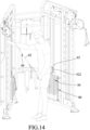
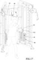
- the cable member 60 can be driven when the handle 70 is pulled, and with the middle section 63 of the cable member 63 of each cable and pulley assembly 20 looping around the counterweight pulley 522 of the corresponding counterweight unit 50 so as to move the same, and through the weight of each counterweight unit 50 and the elasticity of each tension rope unit 80, the user can perform a stand biceps curls exercise, as shown in FIG. 9 , a front raise exercise, as shown in FIG. 10 , a cable one-hand front laterals exercise, as shown in FIG. 11 , a triceps extension exercise, as shown in FIG.
- a triceps push down exercise as shown in FIG. 13
- a one-hand pull down exercise as shown in FIG. 14
- an incline pectoral fly exercise as shown in FIG. 15
- a side pull exercise as shown in FIG. 16
- a cable kickback exercise as shown in FIG. 17
- a bar pull exercise as shown in FIG. 18 .
- the effect of this disclosure resides in that, when the first and second ends 61, 62 of the cable member 60 of each cable and pulley assembly 20 are positioned on the first sliding seat 22 of the corresponding cable and pulley assembly 20, the cable machine exercises can be performed by the user; and, when the first end 61 of the cable member 60 of each cable and pulley assembly 20 is positioned on the corresponding second sliding seat 33, the Smith machine exercises can be performed by the user.
Landscapes
- Health & Medical Sciences (AREA)
- Orthopedic Medicine & Surgery (AREA)
- General Health & Medical Sciences (AREA)
- Physical Education & Sports Medicine (AREA)
- Life Sciences & Earth Sciences (AREA)
- Biophysics (AREA)
- Rehabilitation Tools (AREA)
Claims (6)
- Schnell schaltende umfassende Trainingsvorrichtung (100) umfassend:einen Hauptrahmen (10), beinhaltend einen mittleren Abschnitt (11), zwei Seitenrahmenabschnitte (12), die mit zwei gegenüberliegenden Enden des mittleren Abschnitts (11) verbunden sind, und zwei Paare von Gegengewichtsführungsstangen (13), die jeweils an den Seitenrahmenabschnitten (12) angeordnet sind, wobei jeder der Seitenrahmenabschnitte (12) eine untere Stange (121) beinhaltet, eine obere Stange (122), die der unteren Stange (121) gegenüberliegt, und mindestens eine vertikale Stange (123') mit einer Vielzahl von Aufhängelöchern (1231), die entlang ihrer Länge voneinander beabstandet sind; undzwei Gegengewichtseinheiten (50), die jeweils an den Seitenrahmenabschnitten (12) angeordnet und jeweils entlang der Paare von Gegengewichtsführungsstangen (13) beweglich sind, wobei jede der Gegengewichtseinheiten (50) einen an ihrer Oberseite angeordneten Riemenscheibenhalterung (521) und eine schwenkbar mit der Riemenscheibenhalterung (521) verbundene Gegengewichtsriemenscheibe (522) beinhaltet;dadurch gekennzeichnet, dassder Hauptrahmen (10) ferner zwei Paare von Dämpfungspolstern (14) beinhaltet, die jeweils an den unteren Abschnitten der Paare der Gegengewichtsführungsstangen (13) angeordnet sind, wobei die mindestens eine vertikale Stange (123') zwischen der unteren Stange (121) und der oberen Stange (122) in der Nähe von deren äußeren Enden verbunden ist und von einem entsprechenden Paar der Gegengewichtsführungsstangen (13) beabstandet und parallel zu diesen ist;jeder der Seitenrahmenabschnitte (12) ferner ein Paar erster oberer Riemenscheibenhalterungen (127) und ein Paar zweiter oberer Riemenscheibenhalterungen (128) beinhaltet, die mit der oberen Stange (122) verbunden und zwischen dem äußeren Ende der oberen Stange (122) und der mindestens einen vertikalen Stange (123') angeordnet sind, und ein Paar unterer Riemenscheibenhalterungen (129), die mit der unteren Stange (121) verbunden sind, wobei das Paar erster oberer Riemenscheibenhalterungen (127) eine Seite, die mit der oberen Stange (122) verbunden ist, eine andere Seite, die mit der mindestens einen vertikalen Stange (123') verbunden ist, und eine dritte Seite zwischen der einen Seite und der anderen Seite aufweist;wobei die schnell schaltende umfassende Trainingsvorrichtung (100) ferner umfasst:zwei Seil- und Riemenscheibenbaugruppen (20), die symmetrisch an den Seitenrahmenabschnitten (12) angeordnet sind, wobei jede der Seil- und Riemenscheibenbaugruppen (20) ein Einstellrohr (21) beinhaltet, das zwischen dem Paar unterer Riemenscheibenhalterungen (129) und dem Paar zweiter oberer Riemenscheibenhalterungen (128) eines jeweiligen der Seitenrahmenabschnitte (12) verbunden ist und von der mindestens einen vertikalen Stange (123') beabstandet und parallel zu dieser ist, einen ersten Gleitsitz (22), der auf dem Einstellrohr (21) gleitend gelagert ist, einen Einstellstift (23), der abnehmbar in den ersten Gleitsitz (22) eingesetzt ist, zwei voneinander beabstandete erste obere Riemenscheiben (24), die auf der oberen Stange (122) montiert sind, zwei zweite obere Riemenscheiben (25), die unterhalb der ersten oberen Riemenscheiben (24) angeordnet sind, zwei untere Riemenscheiben (26), die an der unteren Stange (121) montiert sind, und ein Seilelement (60) mit einem ersten Ende (61), einem zweiten Ende (62), das dem ersten Ende (61) gegenüberliegt, und einem Zwischenabschnitt (63), der zwischen dem ersten Ende (61) und dem zweiten Ende (62) des Seilelements (60) verbunden ist, wobei das Einstellrohr (21) eine Vielzahl von Höheneinstelllöchern (211) aufweist, die entlang einer Länge desselben voneinander beabstandet sind, wobei eine der ersten oberen Riemenscheiben (24) schwenkbar mit dem Paar der ersten oberen Riemenscheibenhalterungen (127) verbunden ist, wobei die andere der ersten oberen Riemenscheiben (24) schwenkbar mit dem Paar der zweiten oberen Riemenscheibenhalterungen (128) verbunden ist, wobei die zweiten oberen Riemenscheiben (25) schwenkbar mit dem Paar erster oberer Riemenscheibenhalterungen (127) an der anderen Seite bzw. der dritten Seite verbunden sind;eine Hantelstangeneinheit (30) beinhaltend zwei Gleitführungsstangen (32), die jeweils an den Seitenrahmenabschnitten (12) angeordnet sind, zwei zweite Gleitsitze (33), die jeweils gleitend auf den Gleitführungsstangen (32) gelagert sind, eine Übungsstange (40) mit zwei gegenüberliegenden Enden, die fest und jeweils mit den zweiten Gleitsitzen (33) verbunden sind, und zwei Hakenelemente (34), die drehbar an der Übungsstange (40) in der Nähe der beiden gegenüberliegenden Enden derselben angeordnet sind, wobei jede der Gleitführungsstangen (32) zwischen dem Paar unterer Riemenscheibenhalterungen (129) und dem Paar zweiter oberer Riemenscheibenhalterungen (128) eines jeweiligen der Seitenrahmenabschnitte (12) verbunden ist, und zwischen der mindestens einen vertikalen Stange (123') und dem Einstellrohr (21) angeordnet ist, wobei jedes der Hakenelemente (34) abnehmbar an einem ausgewählten der Aufhängelöcher (311) in der mindestens einen vertikalen Stange (123') des jeweiligen einen der Seitenrahmenabschnitte (12) eingehängt wird, um jeden der zweiten Gleitsitze (33) relativ zu der mindestens einen vertikalen Stange (123') des jeweiligen der Seitenrahmenteile (12) und einer entsprechenden der Gleitführungsstangen (32) zu positionieren; undzwei Spannseileinheiten (80), wobei jede der Spannseileinheiten (80) eine Vielzahl von Spannseilen (81) beinhaltet;wobei, wenn der Einstellstift (23) in den ersten Gleitsitz (22) eingesetzt wird und sich in ein entsprechendes der Höheneinstelllöcher (211) erstreckt, der erste Gleitsitz (22) in einer gewünschten Höhe an dem Einstellrohr (21) befestigt wird;wobei das erste Ende (61) des Seilelements (60) zwischen einer ersten Position, in der das erste Ende (61) des Seilelements (60) auf dem ersten Gleitsitz (22) positioniert ist, um die schnell schaltende umfassende Trainingsvorrichtung (100) in einen ersten Übungsmodus zu versetzen, und einer zweiten Position, in der das erste Ende (61) des Seilelements (60) auf dem zweiten Gleitsitz (33) positioniert ist, beweglich ist, um die schnell schaltende umfassende Trainingsvorrichtung (100) in einen zweiten Übungsmodus zu versetzen;wobei das zweite Ende (62) des Seilelements (60) auf dem ersten Gleitsitz (22) gegenüberliegend dem ersten Ende (61) positioniert ist, und der Zwischenabschnitt (63) des Seilelements (60) um die unteren Riemenscheiben (26), die zweiten oberen Riemenscheiben (25), die Gegengewichtsriemenscheibe (522) und die ersten oberen Riemenscheiben (24) geschlungen ist; undwobei jedes der Spannseile (81) mit einem Ende an der unteren Stange (121) und mit dem anderen Ende abnehmbar an einer entsprechenden der Gegengewichtseinheiten (50) eingehängt ist.
- Schnell schaltende umfassende Trainingsvorrichtung (100) nach Anspruch 1, wobei:jedes der Seitenrahmenabschnitte (12) mindestens eine feste Platte (124) aufweist, die an der unteren Stange (121) angeordnet ist;wobei jede der Gegengewichtseinheiten (50) ferner mindestens eine Spannseilauswahlzahnstange (51, 51'), die auf dem entsprechenden einen Paar der Gegengewichtsführungsstangen (13) gelagert ist, und eine Auswahlstange (52) beinhaltet, die in die mindestens eine Spannseilauswahlzahnstange (51, 51') und quer zu der unteren Stange (121) und der oberen Stange (122) eingesetzt ist;wobei die Riemenscheibenhalterung (521) jeder der Gegengewichtseinheiten (50) oben auf der Auswahlstange (52) angeordnet ist; unddas eine Ende jedes der Spannseile (81) an der mindestens einen festen Platte (124) eingehängt ist, und das andere Ende jedes der Spannseile (81) abnehmbar an der mindestens einen Spannseilauswahlzahnstange (51, 51') eingehängt ist.
- Schnell schaltende umfassende Trainingsvorrichtung (100) nach Anspruch 2, wobei jede der Gegengewichtseinheiten (50) ferner eine Vielzahl von Gegengewichten (53) beinhaltet, die auf der Auswahlstange (52) und dem entsprechenden einen Paar der Gegengewichtsführungsstangen (13) gelagert sind, und einen Auswahlstift (54), der abnehmbar in ein ausgewähltes der Gegengewichte (53) und der Auswahlstange (52) eingesetzt ist.
- Schnell schaltende umfassende Trainingsvorrichtung (100) nach Anspruch 2, wobei die mindestens eine Spannseilauswahlzahnstange eine Vielzahl von Spannseilauswahlzahnstangen (51') beinhaltet, die auf der Auswahlstange (52) und dem entsprechenden Paar der Gegengewichtsführungsstangen (13) gelagert sind, wobei jede der Gegengewichtseinheiten (50) ferner einen Auswahlstift (54) beinhaltet, der abnehmbar in eine ausgewählte der Spannseilauswahlzahnstangen (51') und die Auswahlstange (52) eingesetzt ist, wobei das andere Ende jedes der Spannseile (81) abnehmbar an einem entsprechenden der Spannseilauswahlzahnstangen (51') eingehängt ist.
- Schnell schaltende umfassende Trainingsvorrichtung (100) nach Anspruch 1, wobei:der erste Gleitsitz (22) jeder der Seil- und Riemenscheibenbaugruppen (20) einen ersten Gleitsitzkörper (221), der gleitend auf dem Einstellrohr (21) gelagert ist, ein Schwenkelement (222), das mit einer Seite des ersten Gleitsitzkörpers (221) verbunden ist, die sich distal zu einer entsprechenden der Gleitführungsstangen (32) befindet, ein Paar Riemenscheiben (223), die schwenkbar mit dem Schwenkelement (222) verbunden sind, um das zweite Ende (62) des Seilelements (60) dazwischen zu führen, ein U-förmiges erstes Befestigungselement (224), das mit der anderen Seite des ersten Gleitsitzkörpers (221) und gegenüberliegend dem Schwenkelement (222) verbunden ist, und eine erste Positionierungsplatte (225), die mit dem ersten Gleitsitzkörper (221) verbunden ist und unter dem ersten Befestigungselement (224) angeordnet ist, beinhaltet, wobei das erste Befestigungselement (224) ein Paar von ersten Stiftlöchern (226) aufweist, wobei die erste Positionierungsplatte (225) ein erstes Positionierungsloch (227) aufweist, das durch eine C-förmige Wand definiert ist und sich von einer oberen Fläche der ersten Positionierungsplatte (225) nach innen verjüngt; undjede der genannten Seil- und Riemenscheibenbaugruppen (20) ferner eine Rückhalteeinheit beinhaltet, wobei die Rückhalteeinheit eine Rückhaltekugel (613) beinhaltet, die mit dem ersten Ende (61) des Seilelements (60) verbunden ist, ein Befestigungsteil (611), das oben auf der Rückhaltekugel (613) befestigt ist, und einen Einsetzstift (612) zum Positionieren des ersten Endes (61) des Seilelements (60) in der ersten oder der zweiten Position.
- Schnell schaltende umfassende Trainingsvorrichtung (100) nach Anspruch 5, wobei:jeder der zweiten Gleitsitze (33) einen zweiten Gleitsitzkörper (331) beinhaltet, der gleitend auf einer entsprechenden der Gleitführungsstangen (32) gelagert ist, ein U-förmiges zweites Befestigungselement (332), das an einer Seite des zweiten Gleitsitzkörpers (331) befestigt ist, die sich in der Nähe des Einstellrohrs (21) befindet, und eine zweite Positionierungsplatte (333), die mit dem zweiten Gleitsitzkörper (331) verbunden ist und unter dem zweiten Befestigungselement (332) angeordnet ist, wobei das zweite Befestigungselement (333) ein Paar zweiter Stiftlöcher (334) aufweist, wobei die zweite Positionierungsplatte (333) ein zweites Positionierungsloch (335) aufweist, das durch eine C-förmige Wand definiert ist und sich von einer oberen Fläche der zweiten Positionierungsplatte (335) nach innen verjüngt;wobei der Einsetzstift (612) abnehmbar in das Paar erster Stiftlöcher (226) und das Befestigungsteil (611) eingesetzt wird, um das erste Ende (61) des Seilelements (60) an der ersten Position zu positionieren, und abnehmbar in das Paar von zweiten Stiftlöchern (334) und das Befestigungsteil (611) eingesetzt wird, um das erste Ende (61) des Seilelements (60) an der zweiten Position zu positionieren; undwobei die Rückhaltekugel (613) gegen die erste Positionierungsplatte (225) stößt, wenn sich das erste Ende (61) des Seilelements (60) in der ersten Position befindet, und gegen die zweite Positionierungsplatte (333) stößt, wenn sich das erste Ende (61) des Seilelements (60) in der zweiten Position befindet.
Priority Applications (2)
| Application Number | Priority Date | Filing Date | Title |
|---|---|---|---|
| EP20200035.2A EP3978084B1 (de) | 2020-10-05 | 2020-10-05 | Schnell umschaltende umfassende trainingsvorrichtung |
| ES20200035T ES2987327T3 (es) | 2020-10-05 | 2020-10-05 | Dispositivo de entrenamiento integral de conmutación rápida |
Applications Claiming Priority (1)
| Application Number | Priority Date | Filing Date | Title |
|---|---|---|---|
| EP20200035.2A EP3978084B1 (de) | 2020-10-05 | 2020-10-05 | Schnell umschaltende umfassende trainingsvorrichtung |
Publications (3)
| Publication Number | Publication Date |
|---|---|
| EP3978084A1 EP3978084A1 (de) | 2022-04-06 |
| EP3978084C0 EP3978084C0 (de) | 2024-08-14 |
| EP3978084B1 true EP3978084B1 (de) | 2024-08-14 |
Family
ID=72752314
Family Applications (1)
| Application Number | Title | Priority Date | Filing Date |
|---|---|---|---|
| EP20200035.2A Active EP3978084B1 (de) | 2020-10-05 | 2020-10-05 | Schnell umschaltende umfassende trainingsvorrichtung |
Country Status (2)
| Country | Link |
|---|---|
| EP (1) | EP3978084B1 (de) |
| ES (1) | ES2987327T3 (de) |
Families Citing this family (6)
| Publication number | Priority date | Publication date | Assignee | Title |
|---|---|---|---|---|
| CN114699714B (zh) * | 2022-05-18 | 2026-01-02 | 山东宝迪朗格健身器材有限公司 | 一种稳定可靠的可折叠史密斯训练架 |
| CN115076314A (zh) * | 2022-07-20 | 2022-09-20 | 徐州光海科技有限公司 | 一种便于快速改变传动方向的联动组件 |
| CN217961137U (zh) * | 2022-08-08 | 2022-12-06 | 青岛鹰伯尔运动器材有限公司 | 抓握稳定的多功能综合训练设备 |
| CN115300861B (zh) * | 2022-08-08 | 2023-08-18 | 青岛鹰伯尔运动器材有限公司 | 可多方式使用的综合健身训练设备 |
| DE102023002020A1 (de) | 2023-05-17 | 2024-11-21 | Michael JÖST | Gewichteträger für ein Trainingsgerät |
| CN116920334A (zh) * | 2023-07-26 | 2023-10-24 | 青岛康顿健康产业有限公司 | 背肌训练器 |
Family Cites Families (5)
| Publication number | Priority date | Publication date | Assignee | Title |
|---|---|---|---|---|
| US20020091043A1 (en) * | 2000-12-20 | 2002-07-11 | Rexach Marco L. | Space efficient multi-use exercise apparatus |
| WO2007061410A1 (en) * | 2005-11-22 | 2007-05-31 | Kasper Allison | Adjustable load dynamic active resistance training system |
| CA2850734C (en) * | 2013-06-11 | 2022-07-12 | Dream Visions, Llc. | Exercise apparatus |
| WO2018086028A1 (zh) * | 2016-11-10 | 2018-05-17 | 南通腾泰体育用品有限公司 | 多功能综合史密斯训练器 |
| CN207898846U (zh) | 2017-12-28 | 2018-09-25 | 浙江工业职业技术学院 | 一种可伸缩的新型史密斯机 |
-
2020
- 2020-10-05 EP EP20200035.2A patent/EP3978084B1/de active Active
- 2020-10-05 ES ES20200035T patent/ES2987327T3/es active Active
Also Published As
| Publication number | Publication date |
|---|---|
| EP3978084A1 (de) | 2022-04-06 |
| EP3978084C0 (de) | 2024-08-14 |
| ES2987327T3 (es) | 2024-11-14 |
Similar Documents
| Publication | Publication Date | Title |
|---|---|---|
| US11458350B2 (en) | Fast-switching comprehensive training device | |
| EP3978084B1 (de) | Schnell umschaltende umfassende trainingsvorrichtung | |
| US4257590A (en) | Portable home gymnasium | |
| US4998723A (en) | Cable suspended dumbell and barbell weightlifting apparatus | |
| US4973050A (en) | Pulleyless weightlifting apparatus | |
| US6685601B1 (en) | Compact weightlifting system with safety cage | |
| US4441706A (en) | Weight lifting type exercising device | |
| EP0047312B1 (de) | Faltbares übungsgerät | |
| US7927262B2 (en) | Compact multi-function exercise apparatus | |
| US7223216B1 (en) | Exerciser with multiple bungee cord resistance and enhanced bench movements | |
| US4316609A (en) | Bench mounted weight lifting exerciser | |
| US4286782A (en) | Multi-purpose exercise enhancing device | |
| US4431181A (en) | Collapsible gym apparatus | |
| US10532239B1 (en) | Apparatus for exercising | |
| US4382596A (en) | Weight lifting type exercising device | |
| US4188029A (en) | Multiple use weight lifting exercising device | |
| US20050003938A1 (en) | Adjustable bodyweight exercise apparatus | |
| US20170056702A1 (en) | Gym cage | |
| MXPA03005702A (es) | Aparato para ejercicios, de uso multiple, con aprovechamiento eficiente del espacio. | |
| US20110224057A1 (en) | Universal fitness machine | |
| EP0209563A1 (de) | Gerät für körperübungen. | |
| WO2010149976A2 (en) | Exercise apparatus | |
| US20040014570A1 (en) | Exercise bench | |
| EP0239632B1 (de) | Anordnung für mehrfachübungen | |
| US12036434B2 (en) | Adjustable exercise equipment |
Legal Events
| Date | Code | Title | Description |
|---|---|---|---|
| PUAI | Public reference made under article 153(3) epc to a published international application that has entered the european phase |
Free format text: ORIGINAL CODE: 0009012 |
|
| STAA | Information on the status of an ep patent application or granted ep patent |
Free format text: STATUS: THE APPLICATION HAS BEEN PUBLISHED |
|
| AK | Designated contracting states |
Kind code of ref document: A1 Designated state(s): AL AT BE BG CH CY CZ DE DK EE ES FI FR GB GR HR HU IE IS IT LI LT LU LV MC MK MT NL NO PL PT RO RS SE SI SK SM TR |
|
| STAA | Information on the status of an ep patent application or granted ep patent |
Free format text: STATUS: REQUEST FOR EXAMINATION WAS MADE |
|
| 17P | Request for examination filed |
Effective date: 20220802 |
|
| RBV | Designated contracting states (corrected) |
Designated state(s): AL AT BE BG CH CY CZ DE DK EE ES FI FR GB GR HR HU IE IS IT LI LT LU LV MC MK MT NL NO PL PT RO RS SE SI SK SM TR |
|
| GRAP | Despatch of communication of intention to grant a patent |
Free format text: ORIGINAL CODE: EPIDOSNIGR1 |
|
| STAA | Information on the status of an ep patent application or granted ep patent |
Free format text: STATUS: GRANT OF PATENT IS INTENDED |
|
| INTG | Intention to grant announced |
Effective date: 20240506 |
|
| GRAS | Grant fee paid |
Free format text: ORIGINAL CODE: EPIDOSNIGR3 |
|
| GRAA | (expected) grant |
Free format text: ORIGINAL CODE: 0009210 |
|
| STAA | Information on the status of an ep patent application or granted ep patent |
Free format text: STATUS: THE PATENT HAS BEEN GRANTED |
|
| AK | Designated contracting states |
Kind code of ref document: B1 Designated state(s): AL AT BE BG CH CY CZ DE DK EE ES FI FR GB GR HR HU IE IS IT LI LT LU LV MC MK MT NL NO PL PT RO RS SE SI SK SM TR |
|
| REG | Reference to a national code |
Ref country code: GB Ref legal event code: FG4D |
|
| REG | Reference to a national code |
Ref country code: CH Ref legal event code: EP |
|
| REG | Reference to a national code |
Ref country code: DE Ref legal event code: R096 Ref document number: 602020035656 Country of ref document: DE |
|
| REG | Reference to a national code |
Ref country code: IE Ref legal event code: FG4D |
|
| U01 | Request for unitary effect filed |
Effective date: 20240911 |
|
| U07 | Unitary effect registered |
Designated state(s): AT BE BG DE DK EE FI FR IT LT LU LV MT NL PT RO SE SI Effective date: 20240926 |
|
| U20 | Renewal fee for the european patent with unitary effect paid |
Year of fee payment: 5 Effective date: 20240924 |
|
| REG | Reference to a national code |
Ref country code: ES Ref legal event code: FG2A Ref document number: 2987327 Country of ref document: ES Kind code of ref document: T3 Effective date: 20241114 |
|
| PG25 | Lapsed in a contracting state [announced via postgrant information from national office to epo] |
Ref country code: NO Free format text: LAPSE BECAUSE OF FAILURE TO SUBMIT A TRANSLATION OF THE DESCRIPTION OR TO PAY THE FEE WITHIN THE PRESCRIBED TIME-LIMIT Effective date: 20241114 |
|
| PG25 | Lapsed in a contracting state [announced via postgrant information from national office to epo] |
Ref country code: GR Free format text: LAPSE BECAUSE OF FAILURE TO SUBMIT A TRANSLATION OF THE DESCRIPTION OR TO PAY THE FEE WITHIN THE PRESCRIBED TIME-LIMIT Effective date: 20241115 Ref country code: PL Free format text: LAPSE BECAUSE OF FAILURE TO SUBMIT A TRANSLATION OF THE DESCRIPTION OR TO PAY THE FEE WITHIN THE PRESCRIBED TIME-LIMIT Effective date: 20240814 |
|
| PG25 | Lapsed in a contracting state [announced via postgrant information from national office to epo] |
Ref country code: IS Free format text: LAPSE BECAUSE OF FAILURE TO SUBMIT A TRANSLATION OF THE DESCRIPTION OR TO PAY THE FEE WITHIN THE PRESCRIBED TIME-LIMIT Effective date: 20241214 |
|
| PG25 | Lapsed in a contracting state [announced via postgrant information from national office to epo] |
Ref country code: HR Free format text: LAPSE BECAUSE OF FAILURE TO SUBMIT A TRANSLATION OF THE DESCRIPTION OR TO PAY THE FEE WITHIN THE PRESCRIBED TIME-LIMIT Effective date: 20240814 |
|
| PG25 | Lapsed in a contracting state [announced via postgrant information from national office to epo] |
Ref country code: RS Free format text: LAPSE BECAUSE OF FAILURE TO SUBMIT A TRANSLATION OF THE DESCRIPTION OR TO PAY THE FEE WITHIN THE PRESCRIBED TIME-LIMIT Effective date: 20241114 |
|
| PG25 | Lapsed in a contracting state [announced via postgrant information from national office to epo] |
Ref country code: RS Free format text: LAPSE BECAUSE OF FAILURE TO SUBMIT A TRANSLATION OF THE DESCRIPTION OR TO PAY THE FEE WITHIN THE PRESCRIBED TIME-LIMIT Effective date: 20241114 Ref country code: PL Free format text: LAPSE BECAUSE OF FAILURE TO SUBMIT A TRANSLATION OF THE DESCRIPTION OR TO PAY THE FEE WITHIN THE PRESCRIBED TIME-LIMIT Effective date: 20240814 Ref country code: NO Free format text: LAPSE BECAUSE OF FAILURE TO SUBMIT A TRANSLATION OF THE DESCRIPTION OR TO PAY THE FEE WITHIN THE PRESCRIBED TIME-LIMIT Effective date: 20241114 Ref country code: IS Free format text: LAPSE BECAUSE OF FAILURE TO SUBMIT A TRANSLATION OF THE DESCRIPTION OR TO PAY THE FEE WITHIN THE PRESCRIBED TIME-LIMIT Effective date: 20241214 Ref country code: HR Free format text: LAPSE BECAUSE OF FAILURE TO SUBMIT A TRANSLATION OF THE DESCRIPTION OR TO PAY THE FEE WITHIN THE PRESCRIBED TIME-LIMIT Effective date: 20240814 Ref country code: GR Free format text: LAPSE BECAUSE OF FAILURE TO SUBMIT A TRANSLATION OF THE DESCRIPTION OR TO PAY THE FEE WITHIN THE PRESCRIBED TIME-LIMIT Effective date: 20241115 |
|
| PG25 | Lapsed in a contracting state [announced via postgrant information from national office to epo] |
Ref country code: SM Free format text: LAPSE BECAUSE OF FAILURE TO SUBMIT A TRANSLATION OF THE DESCRIPTION OR TO PAY THE FEE WITHIN THE PRESCRIBED TIME-LIMIT Effective date: 20240814 |
|
| PG25 | Lapsed in a contracting state [announced via postgrant information from national office to epo] |
Ref country code: CZ Free format text: LAPSE BECAUSE OF FAILURE TO SUBMIT A TRANSLATION OF THE DESCRIPTION OR TO PAY THE FEE WITHIN THE PRESCRIBED TIME-LIMIT Effective date: 20240814 |
|
| PG25 | Lapsed in a contracting state [announced via postgrant information from national office to epo] |
Ref country code: SK Free format text: LAPSE BECAUSE OF FAILURE TO SUBMIT A TRANSLATION OF THE DESCRIPTION OR TO PAY THE FEE WITHIN THE PRESCRIBED TIME-LIMIT Effective date: 20240814 |
|
| REG | Reference to a national code |
Ref country code: CH Ref legal event code: PL |
|
| PLBE | No opposition filed within time limit |
Free format text: ORIGINAL CODE: 0009261 |
|
| STAA | Information on the status of an ep patent application or granted ep patent |
Free format text: STATUS: NO OPPOSITION FILED WITHIN TIME LIMIT |
|
| PG25 | Lapsed in a contracting state [announced via postgrant information from national office to epo] |
Ref country code: MC Free format text: LAPSE BECAUSE OF FAILURE TO SUBMIT A TRANSLATION OF THE DESCRIPTION OR TO PAY THE FEE WITHIN THE PRESCRIBED TIME-LIMIT Effective date: 20240814 |
|
| 26N | No opposition filed |
Effective date: 20250515 |
|
| PG25 | Lapsed in a contracting state [announced via postgrant information from national office to epo] |
Ref country code: CH Free format text: LAPSE BECAUSE OF NON-PAYMENT OF DUE FEES Effective date: 20241031 |
|
| U20 | Renewal fee for the european patent with unitary effect paid |
Year of fee payment: 6 Effective date: 20250811 |
|
| PGFP | Annual fee paid to national office [announced via postgrant information from national office to epo] |
Ref country code: GB Payment date: 20250801 Year of fee payment: 6 |
|
| PG25 | Lapsed in a contracting state [announced via postgrant information from national office to epo] |
Ref country code: IE Free format text: LAPSE BECAUSE OF NON-PAYMENT OF DUE FEES Effective date: 20241005 |
|
| PG25 | Lapsed in a contracting state [announced via postgrant information from national office to epo] |
Ref country code: CY Free format text: LAPSE BECAUSE OF FAILURE TO SUBMIT A TRANSLATION OF THE DESCRIPTION OR TO PAY THE FEE WITHIN THE PRESCRIBED TIME-LIMIT; INVALID AB INITIO Effective date: 20201005 |
|
| PGFP | Annual fee paid to national office [announced via postgrant information from national office to epo] |
Ref country code: ES Payment date: 20251118 Year of fee payment: 6 |