EP3977851A1 - Tine weeding device for soil working with synchronously adjustable tines - Google Patents
Tine weeding device for soil working with synchronously adjustable tines Download PDFInfo
- Publication number
- EP3977851A1 EP3977851A1 EP20199966.1A EP20199966A EP3977851A1 EP 3977851 A1 EP3977851 A1 EP 3977851A1 EP 20199966 A EP20199966 A EP 20199966A EP 3977851 A1 EP3977851 A1 EP 3977851A1
- Authority
- EP
- European Patent Office
- Prior art keywords
- tines
- rows
- harrow
- pivoting
- folded
- Prior art date
- Legal status (The legal status is an assumption and is not a legal conclusion. Google has not performed a legal analysis and makes no representation as to the accuracy of the status listed.)
- Granted
Links
- 239000002689 soil Substances 0.000 title claims abstract description 17
- 238000009333 weeding Methods 0.000 title 1
- 230000003370 grooming effect Effects 0.000 claims abstract description 37
- 230000008878 coupling Effects 0.000 claims description 11
- 238000010168 coupling process Methods 0.000 claims description 11
- 238000005859 coupling reaction Methods 0.000 claims description 11
- 230000001360 synchronised effect Effects 0.000 claims description 4
- 238000003971 tillage Methods 0.000 claims description 2
- 230000035515 penetration Effects 0.000 description 4
- 241000196324 Embryophyta Species 0.000 description 3
- 239000002184 metal Substances 0.000 description 3
- 235000011293 Brassica napus Nutrition 0.000 description 1
- 240000008100 Brassica rapa Species 0.000 description 1
- 235000000540 Brassica rapa subsp rapa Nutrition 0.000 description 1
- 241000209140 Triticum Species 0.000 description 1
- 235000021307 Triticum Nutrition 0.000 description 1
- 230000001419 dependent effect Effects 0.000 description 1
- 238000009329 organic farming Methods 0.000 description 1
- 239000000126 substance Substances 0.000 description 1
Images


Classifications
-
- A—HUMAN NECESSITIES
- A01—AGRICULTURE; FORESTRY; ANIMAL HUSBANDRY; HUNTING; TRAPPING; FISHING
- A01B—SOIL WORKING IN AGRICULTURE OR FORESTRY; PARTS, DETAILS, OR ACCESSORIES OF AGRICULTURAL MACHINES OR IMPLEMENTS, IN GENERAL
- A01B19/00—Harrows with non-rotating tools
- A01B19/10—Lifting or cleaning apparatus
-
- A—HUMAN NECESSITIES
- A01—AGRICULTURE; FORESTRY; ANIMAL HUSBANDRY; HUNTING; TRAPPING; FISHING
- A01B—SOIL WORKING IN AGRICULTURE OR FORESTRY; PARTS, DETAILS, OR ACCESSORIES OF AGRICULTURAL MACHINES OR IMPLEMENTS, IN GENERAL
- A01B35/00—Other machines for working soil not specially adapted for working soil on which crops are growing
- A01B35/02—Other machines for working soil not specially adapted for working soil on which crops are growing with non-rotating tools
- A01B35/04—Other machines for working soil not specially adapted for working soil on which crops are growing with non-rotating tools drawn by animal or tractor or man-power
- A01B35/06—Other machines for working soil not specially adapted for working soil on which crops are growing with non-rotating tools drawn by animal or tractor or man-power with spring tools or with resiliently- or flexibly-attached rigid tools
-
- A—HUMAN NECESSITIES
- A01—AGRICULTURE; FORESTRY; ANIMAL HUSBANDRY; HUNTING; TRAPPING; FISHING
- A01B—SOIL WORKING IN AGRICULTURE OR FORESTRY; PARTS, DETAILS, OR ACCESSORIES OF AGRICULTURAL MACHINES OR IMPLEMENTS, IN GENERAL
- A01B39/00—Other machines specially adapted for working soil on which crops are growing
- A01B39/12—Other machines specially adapted for working soil on which crops are growing for special purposes, e.g. for special culture
- A01B39/18—Other machines specially adapted for working soil on which crops are growing for special purposes, e.g. for special culture for weeding
-
- A—HUMAN NECESSITIES
- A01—AGRICULTURE; FORESTRY; ANIMAL HUSBANDRY; HUNTING; TRAPPING; FISHING
- A01B—SOIL WORKING IN AGRICULTURE OR FORESTRY; PARTS, DETAILS, OR ACCESSORIES OF AGRICULTURAL MACHINES OR IMPLEMENTS, IN GENERAL
- A01B73/00—Means or arrangements to facilitate transportation of agricultural machines or implements, e.g. folding frames to reduce overall width
- A01B73/02—Folding frames
- A01B73/04—Folding frames foldable about a horizontal axis
- A01B73/044—Folding frames foldable about a horizontal axis the axis being oriented in a longitudinal direction
-
- A—HUMAN NECESSITIES
- A01—AGRICULTURE; FORESTRY; ANIMAL HUSBANDRY; HUNTING; TRAPPING; FISHING
- A01M—CATCHING, TRAPPING OR SCARING OF ANIMALS; APPARATUS FOR THE DESTRUCTION OF NOXIOUS ANIMALS OR NOXIOUS PLANTS
- A01M21/00—Apparatus for the destruction of unwanted vegetation, e.g. weeds
- A01M21/02—Apparatus for mechanical destruction
Landscapes
- Life Sciences & Earth Sciences (AREA)
- Engineering & Computer Science (AREA)
- Mechanical Engineering (AREA)
- Soil Sciences (AREA)
- Environmental Sciences (AREA)
- Zoology (AREA)
- Soil Working Implements (AREA)
- Agricultural Machines (AREA)
Abstract
Die Erfindung betrifft eine Striegelvorrichtung (10) zur Bodenbearbeitung, umfassend ein Fahrwerk (12); eine mit dem Fahrwerk (12) verbundene Rahmenstruktur (14); mehrere bezogen auf die Längsrichtung (x) der Striegelvorrichtung (10) hintereinander angeordnete Zinkenreihen (24), die jeweils mehrere in Querrichtung (y) der Striegelvorrichtung (10) nebeneinander angeordnete Striegelzinken (26) zur Bodenbearbeitung aufweisen; wobei die Zinkenreihen (24) miteinander gekoppelt verschwenkbar an der Rahmenstruktur (14) gelagert sind, sodass eine Verschwenkung der Zinkenreihen (24) eine synchrone Verschwenkung der Striegelzinken (26) zwischen verschieden weit ausgefahrenen Stellungen bewirkt.The invention relates to a harrowing device (10) for soil cultivation, comprising a chassis (12); a frame structure (14) connected to the landing gear (12); a plurality of rows of tines (24) arranged one behind the other in relation to the longitudinal direction (x) of the grooming device (10), each having a plurality of grooming tines (26) arranged next to one another in the transverse direction (y) of the grooming device (10) for tilling the soil; the rows of tines (24) being pivotably coupled to one another and mounted on the frame structure (14), so that pivoting the rows of tines (24) causes the harrow tines (26) to pivot synchronously between positions that are extended to different extents.
Description
Die vorliegende Erfindung betrifft eine Striegelvorrichtung zur Bodenbearbeitung mit synchron verstellbaren Striegelzinken.The present invention relates to a harrow device for soil cultivation with synchronously adjustable harrow tines.
Striegelvorrichtungen, auch Hackstriegel genannt, sind ein der Egge ähnliches, landwirtschaftliches Arbeitsgerät, welches zur mechanischen Unkrautbekämpfung eingesetzt wird. Solche Striegelvorrichtungen können beispielsweise mittels eines Traktors über einen Acker gezogen werden. Üblicherweise umfassen solche Striegelvorrichtungen mehrere Striegelzinken in Form von Metallhaken, die insbesondere kleine Unkrautpflanzen in oberen Bodenschichten ausreißen und verschütten können. Stärkere Kulturpflanzen, beispielsweise Rüben, Weizen und dergleichen, bleiben bei der Verwendung solcher Striegelvorrichtungen üblicherweise stehen. Auf diese Weise können chemische Unkrautvernichtungsmittel vermieden werden, weshalb solche Striegelvorrichtungen insbesondere auch in der ökologischen Landwirtschaft eingesetzt werden.Harrow devices, also called tine weeders, are agricultural implements similar to harrows, which are used for mechanical weed control. Such harrowing devices can, for example, be pulled over a field by means of a tractor. Usually, such harrow devices include several harrow tines in the form of metal hooks, which can uproot and spill small weed plants in particular in the upper soil layers. Stronger crops, such as turnips, wheat and the like, usually remain standing when using such combing devices. In this way, chemical weed killers can be avoided, which is why such harrow devices are used in particular in organic farming.
Je nach zu bearbeitendem Boden beziehungsweise Acker kann es dabei wünschenswert sein, die üblicherweise als Metallhaken ausgebildeten Striegelzinken in unterschiedliche Stellungen auszufahren, um eine Eindringtiefe der Striegelzinken in den zu bearbeitenden Boden einzustellen.Depending on the soil or field to be worked, it may be desirable to extend the harrow tines, which are usually designed as metal hooks, into different positions in order to adjust the depth of penetration of the harrow tines into the soil to be worked.
Es ist die Aufgabe der vorliegenden Erfindung, eine Striegelvorrichtung zur Bodenbearbeitung bereitzustellen, die auf besonders einfache Weise die Einstellbarkeit einer Bearbeitungstiefe solcher Striegelzinken ermöglicht.It is the object of the present invention to provide a harrowing device for soil cultivation, which enables the adjustment of a working depth of such harrow tines in a particularly simple manner.
Diese Aufgabe wird durch eine Striegelvorrichtung zur Bodenbearbeitung mit den Merkmalen des Anspruchs 1 gelöst. Weitere mögliche Ausgestaltungen der Erfindung sind in den abhängigen Ansprüchen, in der Beschreibung und den Figuren angegeben.This object is achieved by a harrowing device for soil cultivation with the features of claim 1. Further possible configurations of the invention are specified in the dependent claims, in the description and in the figures.
Die erfindungsgemäße Striegelvorrichtung zur Bodenbearbeitung umfasst ein Fahrwerk und eine mit dem Fahrwerk verbundene Rahmenstruktur. Des Weiteren weist die Striegelvorrichtung mehrere bezogen auf die Längsrichtung der Striegelvorrichtung hintereinander angeordnete Zinkenreihen auf, die jeweils mehrere in Querrichtung der Striegelvorrichtung nebeneinander angeordnete Striegelzinken zur Bodenbearbeitung aufweisen. Die Zinkenreihen sind miteinander gekoppelt verschwenkbar an der Rahmenstruktur gelagert, sodass eine Verschwenkung der Zinkenreihen eine synchrone Verschwenkung der Striegelzinken zwischen verschieden weit ausgefahrenen Stellungen bewirkt. Insbesondere können die jeweiligen Zinkenreihen um Achsen verschwenkt werden, die zumindest im Wesentlichen in Querrichtung der Striegelvorrichtung verlaufen. Durch Verschwenken der Zinkenreihen wird also eine entsprechende Verschwenkung der jeweiligen Striegelzinken bewirkt, infolgedessen diese in unterschiedliche weit ausgefahrene Stellungen bewegt werden können, sodass eine Verstellung der jeweiligen Striegelzinken dahingehend erfolgen kann, dass deren Eindringtiefe in den Boden eingestellt beziehungsweise verändert wird.The harrowing device according to the invention for working the soil comprises a chassis and a frame structure connected to the chassis. Furthermore, the grooming device has several relative to the longitudinal direction of the grooming device rows of tines arranged one behind the other, each having a plurality of harrow tines arranged next to one another in the transverse direction of the harrow device for tilling the soil. The rows of tines are pivotably coupled to one another and mounted on the frame structure, so that pivoting the rows of tines causes the harrow tines to pivot synchronously between positions that are extended to different extents. In particular, the respective rows of tines can be pivoted about axes which run at least essentially in the transverse direction of the grooming device. By pivoting the rows of tines, a corresponding pivoting of the respective harrow tines is effected, as a result of which they can be moved into different far extended positions, so that the respective harrow tines can be adjusted such that their penetration depth into the soil is adjusted or changed.
Ein wesentlicher Vorteil der erfindungsgemäßen Striegelvorrichtung liegt darin, dass die Zinkenreihen miteinander gekoppelt verschwenkbar an der Rahmenstruktur gelagert sind. Das Verschwenken von einer der Zinkenreihen bewirkt also automatisch das Verschwenken der übrigen Zinkenreihen, was wiederum eine synchrone Verschwenkung beziehungsweise Verstellung der Striegelzinken bewirkt. Bei der erfindungsgemäßen Striegelvorrichtung ist es also nicht notwendig, die Zinkenreihen einzeln zu verschwenken beziehungsweise zu verstellen, um eine Eindringtiefe der Striegelzinken einzustellen. Denn bei der erfindungsgemäßen Striegelvorrichtung sind die Striegelzinken zumindest mittelbar miteinander verbunden beziehungsweise gekoppelt, sodass eine Verschwenkung der Striegelzinken immer synchron erfolgt. Die Striegelzinken müssen also nicht einzeln eingestellt beziehungsweise verschwenkt werden, genauso wenig die Zinkenreihen. Bei der erfindungsgemäßen Striegelvorrichtung kann also die Eindringtiefe der Striegelzinken besonders einfach und schnell und insbesondere synchron verändert werden.An essential advantage of the harrowing device according to the invention is that the rows of tines are coupled to one another and are pivotably mounted on the frame structure. The pivoting of one of the rows of tines thus automatically causes the other rows of tines to pivot, which in turn causes a synchronous pivoting or adjustment of the harrow tines. With the harrowing device according to the invention, it is therefore not necessary to pivot or adjust the rows of tines individually in order to adjust the depth of penetration of the harrowing tines. Because in the harrow device according to the invention, the harrow tines are at least indirectly connected or coupled to one another, so that the harrow tines are always pivoted synchronously. The harrow tines therefore do not have to be adjusted or pivoted individually, nor do the rows of tines. With the harrow device according to the invention, the penetration depth of the harrow tines can be changed particularly easily and quickly and in particular synchronously.
Eine mögliche Ausgestaltung der Erfindung sieht vor, dass die Striegelvorrichtung einen verstellbaren Anschlag aufweist, der die Verschwenkbewegung der Zinkenreihen und damit eine Arbeitstiefe der Striegelzinken begrenzt. Durch den Anschlag wird also die Verschwenkbewegung der Zinkenreihen eingeschränkt, sodass eine bestimmte gewollte Arbeitstiefe nicht unterschritten werden kann. Dadurch, dass der Anschlag verstellbar ist, ist es auf einfache Weise möglich, eine jeweils gewünschte Arbeitstiefe bei den Zinkenreihen und somit den Striegelzinken einzustellen. Je nachdem, wie weit der Anschlag ausgefahren oder eingefahren ist, begrenzt dieser also den Spielraum für Bewegungen beziehungsweise Verschwenkungen der Zinkenreihen, infolgedessen die Arbeitstiefe der Striegelzinken entsprechend begrenzt werden kann. Da die Bewegungen der Zinkenreihen miteinander gekoppelt sind, reicht ein einziger Anschlag aus, um die Arbeitstiefe bei den Striegelzinken einzustellen.A possible embodiment of the invention provides that the harrow device has an adjustable stop, which limits the pivoting movement of the rows of tines and thus a working depth of the harrow tines. The pivoting movement of the rows of tines is thus restricted by the stop, so that a certain desired working depth cannot be fallen below. Because the stop is adjustable, it is easily possible to set a desired working depth for the tine rows and thus the harrow tines. Depending on how far the stop is extended or retracted, this limits the scope for movements, respectively Pivoting of the rows of tines, as a result of which the working depth of the harrow tines can be limited accordingly. Since the movements of the rows of tines are linked to one another, a single stop is sufficient to adjust the working depth of the harrow tines.
Eine weitere mögliche Ausgestaltung der Erfindung sieht vor, dass der Anschlag mittels einer Spindel, elektronisch und/oder mittels eines Bolzens und zugehörigen Stecksystems verstellbar und arretierbar ist. Über eine Spindel kann beispielsweise der Anschlag ganz einfach ausgefahren und eingefahren werden, um die Arbeitstiefe der Striegelzinken zu begrenzen beziehungsweise einzustellen. Das Ganze kann zusätzlich oder alternativ noch elektronisch erfolgen, beispielsweise über eine entsprechende Steuerung und einen entsprechenden Aktor. Auch ist es beispielsweise möglich, dass der Anschlag in einer entsprechenden Führung translatorisch beweglich gelagert ist, wobei ein Bolzen mit einem zugehörigen Stecksystem und entsprechenden Löchern vorgesehen sein kann, um den Anschlag an unterschiedlichen Positionen zu fixieren. Letzteres ermöglicht eine besonders einfache und manuelle Einstellbarkeit des Anschlags und somit der Arbeitstiefe der Striegelzinken.A further possible embodiment of the invention provides that the stop can be adjusted and locked by means of a spindle, electronically and/or by means of a bolt and associated plug-in system. For example, the stop can be easily extended and retracted via a spindle in order to limit or adjust the working depth of the harrow tines. The whole thing can additionally or alternatively take place electronically, for example via a corresponding controller and a corresponding actuator. It is also possible, for example, for the stop to be mounted in a corresponding guide so that it can move in a translatory manner, in which case a bolt with an associated plug-in system and corresponding holes can be provided in order to fix the stop at different positions. The latter enables the stop and thus the working depth of the harrow tines to be adjusted particularly easily and manually.
In weiterer möglicher Ausgestaltung der Erfindung ist es vorgesehen, dass die Striegelvorrichtung mit nur einem Aktor zum Verschwenken aller Zinkenreihen aufweist. Durch die Kopplung der Bewegung der Zinkenreihen ist es möglich, nur einen einzigen Aktor zum Verschwenken aller Zinkenreihen zu verwenden. Je nach Gewicht und Maßen der Striegelvorrichtung ist es aber auch möglich, dass die Verstellvorrichtung mehrere Aktoren aufweist, um eine zuverlässige Verschwenkbewegung der Zinkenreihen und somit eine zuverlässige Einstellung der gewünschten Arbeitstiefe der Striegelzinken bewirken zu können. Als Aktor kann beispielsweise ein Hydraulikzylinder verwendet werden, wobei auch andere Antriebsmittel beziehungsweise Aktoren möglich sind.In a further possible embodiment of the invention, it is provided that the grooming device has only one actuator for pivoting all rows of tines. By coupling the movement of the rows of tines, it is possible to use only a single actuator for pivoting all rows of tines. Depending on the weight and dimensions of the harrow device, however, it is also possible for the adjustment device to have several actuators in order to be able to bring about a reliable pivoting movement of the rows of tines and thus a reliable setting of the desired working depth of the harrow tines. A hydraulic cylinder, for example, can be used as an actuator, although other drive means or actuators are also possible.
Gemäß einer weiteren möglichen Ausgestaltung der Erfindung ist es vorgesehen, dass die Zinkenreihen jeweilige verschwenkbar an der Rahmenstruktur gelagerte Stangen aufweisen, an denen die Striegelzinken zumindest mittelbar befestigt sind, wobei die Stangen der Zinkenreihen miteinander gekoppelt sind. Die Stangen können beispielsweise an ihren jeweiligen Längsenden verdrehbar beziehungsweise verschwenkbar an der Rahmenstruktur gelagert sein. Die Stangen können wiederum über weitere Stangen unmittelbar oder mittelbar verbunden sein, mittels derer die Bewegungskopplung der Zinkenreihen sichergestellt werden kann.According to a further possible embodiment of the invention, it is provided that the rows of tines have rods which are pivotably mounted on the frame structure and to which the comb tines are at least indirectly attached, the rods of the rows of tines being coupled to one another. The rods can, for example, be rotatably or pivotably mounted on the frame structure at their respective longitudinal ends. The rods can in turn have more rods directly or be indirectly connected, by means of which the movement coupling of the rows of tines can be ensured.
Eine weitere mögliche Ausgestaltung der Erfindung sieht vor, dass die Rahmenstruktur ein Mittelteil und ein rechtes Seitenteil sowie ein linkes Seitenteil aufweist, die alle mit den Zinkenreihen versehen sind, wobei die Seitenteile zwischen einer heruntergeklappten Arbeitsstellung und einer hochgeklappten Transportstellung verschwenkbar am Mittelteil gelagert sind. Bei Bedarf kann so also eine besonders große Arbeitsbreite der Striegelvorrichtung realisiert werden, nämlich, wenn die beiden Seitenteile in ihrer heruntergeklappten Arbeitsstellung angeordnet sind. In der heruntergeklappten Arbeitsstellung kann es insbesondere vorgesehen sein, dass das Mittelteil und die Seitenteile auf derselben Höhe angeordnet sind. Spätestens wenn die Striegelvorrichtung über öffentliche Verkehrswege, insbesondere Straßen, bewegt werden muss, können die beiden Seitenteile in ihre hochgeklappte Transportstellung bewegt werden, sodass durch die Straßenverkehrsordnung festgelegte Maximalbreiten nicht überschritten werden.Another possible embodiment of the invention provides that the frame structure has a middle part and a right side part and a left side part, all of which are provided with the rows of tines, the side parts being pivotably mounted on the middle part between a folded-down working position and a folded-up transport position. If necessary, a particularly large working width of the harrowing device can be realized, namely when the two side parts are arranged in their folded-down working position. In the folded-down working position, provision can in particular be made for the central part and the side parts to be arranged at the same height. The two side parts can be moved into their folded-up transport position at the latest when the harrowing device has to be moved on public roads, in particular streets, so that the maximum widths specified by the road traffic regulations are not exceeded.
In weiterer möglicher Ausgestaltung der Erfindung ist es vorgesehen, dass eine Verschwenkung der Seitenteile in die Transportstellung mit einer Verschwenkung der Striegelzinken in eine herangeklappte Fahrstellung gekoppelt ist. Die Striegelzinken sind in ihrer herangeklappten Fahrstellung maximal möglich an die Rahmenstruktur herangeschwenkt beziehungsweise herangeklappt. Dadurch, dass die Verschwenkung der Seitenteile in die Transportstellung mit der Verschwenkung der Striegelzinken in ihre herangeklappte Fahrstellung gekoppelt ist, kann in der Transportstellung sichergestellt werden, dass die Striegelzinken möglichst wenig seitlich hervorstehen und somit die Breite der Striegelvorrichtung zumindest im Wesentlichen gar nicht weiter beeinflussen. Dadurch kann die Rahmenstruktur der Striegelvorrichtung ziemlich breit ausgeführt werden, da die Striegelzinken in der Transportstellung der Seitenteile so gut wir gar nicht zur Breite der Striegelvorrichtung beitragen.In a further possible embodiment of the invention, it is provided that a pivoting of the side parts into the transport position is coupled with a pivoting of the harrow tines into a folded driving position. In their folded-up driving position, the harrow tines are pivoted or folded up to the maximum possible extent against the frame structure. Due to the fact that the pivoting of the side parts into the transport position is coupled with the pivoting of the harrow tines into their folded driving position, it can be ensured in the transport position that the harrow tines protrude as little as possible laterally and thus at least essentially have no further influence on the width of the harrow device. As a result, the frame structure of the grooming device can be made quite wide, since the grooming tines in the transport position of the side parts do not contribute to the width of the grooming device.
Gemäß einer weiteren möglichen Ausgestaltung der Erfindung ist es vorgesehen, dass die Kopplung der Verschwenkung der Seitenteile in die Transportstellung mit der Verschwenkung der Striegelzinken in die herangeklappte Fahrstellung mechanisch und/oder hydraulisch realisiert ist. Eine hydraulische Realisierung kann beispielsweise derart sein, dass jeweilige Hydraulikzylinder vorgesehen sind, um einerseits die Striegelzinken zu verschwenken und andererseits die Seitenteile hochzuklappen beziehungsweise herunterzuklappen. Durch Betätigung entsprechender Ventile in einem Hydraulikkreislauf kann sichergestellt werden, dass eine hydraulische Kopplung derart realisiert ist, dass das Verschwenken der Seitenteile in die Transportstellung automatisch auch das Verschwenken der Striegelzinken in ihre herangeklappte Fahrstellung bewirkt. Eine mechanische Kopplung kann beispielsweise durch entsprechende Koppelgetriebe oder anderweitige Maßnahmen realisiert sein, sodass beim Verschwenken der Seitenteile automatisch mit Einnehmen der Transportstellung die Striegelzinken in ihre herangeklappte Fahrstellung bewegt werden.According to a further possible embodiment of the invention, it is provided that the coupling of the pivoting of the side parts into the transport position with the pivoting of the harrow tines into the folded driving position is realized mechanically and/or hydraulically. A hydraulic implementation can, for example, be such that respective hydraulic cylinders are provided in order on the one hand to pivot the harrow tines and on the other hand to fold up or respectively the side parts to fold down. By actuating corresponding valves in a hydraulic circuit, it can be ensured that a hydraulic coupling is realized in such a way that pivoting the side parts into the transport position also automatically causes the harrow tines to pivot into their folded driving position. A mechanical coupling can be implemented, for example, by means of a corresponding linkage or other measures, so that when the side parts are pivoted, the harrow tines are automatically moved into their folded-up driving position when the transport position is assumed.
Weitere Merkmale der Erfindung können sich aus der nachfolgenden Figurenbeschreibung sowie anhand der Zeichnung ergeben. Die vorstehend in der Beschreibung genannten Merkmale und Merkmalskombinationen sowie die nachfolgend in der Figurenbeschreibung und/oder in den Figuren alleine gezeigten Merkmale und Merkmalskombinationen sind nicht nur in der jeweils angegebenen Kombination, sondern auch in anderen Kombinationen oder in Alleinstellung verwendbar, ohne den Rahmen der Erfindung zu verlassen.Further features of the invention can result from the following description of the figures and from the drawing. The features and feature combinations mentioned above in the description and the features and feature combinations shown below in the description of the figures and/or in the figures alone can be used not only in the combination specified in each case, but also in other combinations or on their own, without going beyond the scope of the invention to leave.
Die Zeichnung zeigt in:
- Fig. 1
- eine Perspektivansicht einer Striegelvorrichtung zur Bodenbearbeitung;
- Fig. 2
- eine Perspektivansicht eines Ausschnitts der Striegelvorrichtung, in dem ein verstellbarer Anschlag der Striegelvorrichtung zu erkennen ist;
- Fig. 3
- eine teilweise geschnittene Seitenansicht der Striegelvorrichtung, wobei verschiedene Striegelzinken der Striegelvorrichtung in unterschiedlich weit ausgeklappten beziehungsweise heruntergeklappten Stellungen zu erkennen sind;
- Fig. 4
- eine weitere teilweise geschnittene Seitenansicht der Striegelvorrichtung, wobei die Striegelzinken in einer herangeklappten beziehungsweise hochgeklappten Fahrstellung angeordnet sind;
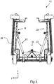
- Fig. 5
- eine Frontalansicht der Striegelvorrichtung, wobei jeweilige Seitenteile der Striegelvorrichtung in eine Transportstellung nach oben geklappt worden sind.
- 1
- a perspective view of a harrow device for tillage;
- 2
- a perspective view of a section of the grooming device, in which an adjustable stop of the grooming device can be seen;
- 3
- a partially sectioned side view of the grooming device, wherein different grooming tines of the grooming device can be seen in positions that are folded out or folded down to different extents;
- 4
- a further partially sectioned side view of the grooming device, the grooming tines being arranged in a folded-up or folded-up driving position;
- figure 5
- a front view of the grooming device, wherein respective side parts of the grooming device have been folded up into a transport position.
Gleiche oder funktionsgleiche Elemente sind in den Figuren mit den gleichen Bezugszeichen versehen.Elements that are the same or have the same function are provided with the same reference symbols in the figures.
Eine Striegelvorrichtung 10 zur Bodenbearbeitung ist in einer Perspektivansicht in
Bezogen auf die Längsrichtung x der Striegelvorrichtung 10 weist diese mehrere hintereinander angeordnete Zinkenreihen 24 auf, wobei der Übersichtlichkeit halber nicht alle Zinkenreihen 24 vorliegend mit Bezugszeichen versehen worden sind. Beide Seitenteile 18, 20 und das Mittelteil 16 sind jeweils mit sechs solcher Zinkenreihen 24 ausgestattet. Die Anzahl der Zinkenreihen 24 ist selbstverständlich nur rein beispielhaft zu verstehen und kann je nach Anwendungsfall auch unterschiedlich ausfallen.Relative to the longitudinal direction x of the
Jede Zinkenreihe 24 weist mehrere in Querrichtung y der Striegelvorrichtung 10 nebeneinander angeordnete Striegelzinken 26 zur Bodenbearbeitung auf. Der Übersichtlichkeit halber wurde nur einer der Striegelzinken 26 vorliegend mit einem Bezugszeichen versehen. Bei den Striegelzinken 26 kann es sich insbesondere um Metallhaken handeln.Each row of
Die jeweiligen Zinkenreihen 24 sind miteinander gekoppelt verschwenkbar an der Rahmenstruktur 14 gelagert, sodass eine Verschwenkung der Zinkenreihen 24 eine synchrone Verschwenkung der Striegelzinken 26 zwischen verschieden weit ausgefahrenen Stellungen bewirkt.The respective rows of
Vorliegend weist die Striegelvorrichtung 10 drei Hydraulikzylinder 28 auf, die dazu eingerichtet sind, die Zinkenreihen 24 am Mittelteil 16 und an den Seitenteilen 18, 20 zu verschwenken, um die Striegelzinken 26 zwischen verschieden weit ausgefahrenen Stellungen zu verschwenken. Auf diese Weise ist es möglich, die Striegelzinken 26 unterschiedlich weit nach unten auszufahren beziehungsweise nach oben einzufahren, sodass eine Bearbeitungstiefe für einen zu bearbeitenden Boden ganz einfach eingestellt werden kann. Die Zinkenreihen 24 müssen also nicht einzeln verstellt werden, geschweige denn die Striegelzinken 26. Stattdessen müssen im hier gezeigten Fall lediglich die Hydraulikzylinder 28 betätigt werden, um an den Seitenteilen 18, 20 und am Mittelteil 16 die Zinkenreihen 24 und somit die Striegelzinken 26 synchron miteinander zu verschwenken beziehungsweise zu verstellen.In the present case, the
Die Striegelzinken 26 sind je Zinkenreihe 24 an jeweiligen Stangen 30 befestigt, die Bestandteil der jeweiligen Zinkenreihen 24 sind. Diese Stangen 30 sind verschwenkbar an der Rahmenstruktur 14, also am Mittelteil 16 beziehungsweise an den Seitenteilen 18, 20 gelagert. Des Weiteren weisen die Zinkenreihen 24 im hier gezeigten Fall Koppelstangen 32 auf, die zumindest mittelbar mit den Stangen 30 verbunden sind. Die Koppelstangen 32 sind wiederum über jeweilige Verbindungsstangen 34 miteinander verbunden, an denen die jeweiligen Hydraulikzylinder 28 angreifen. Der Übersichtlichkeit halber wurden die Stangen 30, Koppelstangen 32 und Verbindungsstangen 34 nur jeweils einmal mit Bezugszeichen versehen.The harrow tines 26 are fastened to
Die Striegelvorrichtung 10 umfasst des Weiteren einen Anschlag 36, der in
In
In
In
In
Mittels der erläuterten Striegelvorrichtung 10 ist es auf ganz einfache und schnelle Weise möglich, eine Bearbeitungstiefe der Striegelzinken 26 einzustellen, da ein Verschwenken der Zinkenreihen 24 (siehe
Auch ist es möglich, wie in
- 1010
- Striegelvorrichtunggrooming device
- 1212
- Fahrwerklanding gear
- 1414
- Rahmenstrukturframe structure
- 1616
- Mittelteilcenter part
- 1818
- linkes Seitenteilleft side panel
- 2020
- rechtes Seitenteilright side panel
- 2222
- Hydraulikzylinderhydraulic cylinder
- 2424
- Zinkenreihenrows of tines
- 2626
- Striegelzinkenharrow tines
- 2828
- Hydraulikzylinderhydraulic cylinder
- 3030
- Stangen der Zinkenreihenrods of the rows of tines
- 3232
- Koppelstangenconnecting rods
- 3434
- Verbindungsstangenconnecting rods
- 3636
- Anschlagattack
- xx
- Längsrichtung der StriegelvorrichtungLongitudinal direction of the harrow device
- yy
- Querrichtung der StriegelvorrichtungTransverse direction of the harrow device
- ze.g
- Hochrichtung der StriegelvorrichtungElevation of the harrow device
Claims (8)
dadurch gekennzeichnet, dass
die Striegelvorrichtung (10) einen verstellbaren Anschlag (36) aufweist, der die Verschwenkbewegung der Zinkenreihen (24) und damit eine Arbeitstiefe der Striegelzinken (26) begrenzt.Grooming device (10) according to claim 1,
characterized in that
the harrow device (10) has an adjustable stop (36) which limits the pivoting movement of the rows of tines (24) and thus a working depth of the harrow tines (26).
dadurch gekennzeichnet, dass
der Anschlag (36) mittels einer Spindel, elektronisch und/oder mittels eines Bolzens und zugehörigen Stecksystems verstellbar und arretierbar ist.Grooming device (10) according to claim 2,
characterized in that
the stop (36) can be adjusted and locked by means of a spindle, electronically and/or by means of a bolt and associated plug-in system.
dadurch gekennzeichnet, dass
die Striegelvorrichtung (10) eine Verstellvorrichtung mit nur einem Aktor zum Verschwenken aller Zinkenreihen (24) aufweist.Grooming device (10) according to one of the preceding claims,
characterized in that
the grooming device (10) has an adjustment device with only one actuator for pivoting all rows of tines (24).
dadurch gekennzeichnet, dass
die Zinkenreihen (24) jeweilige verschwenkbar an der Rahmenstruktur (14) gelagerte Stangen (30) aufweisen, an denen die Striegelzinken (26) zumindest mittelbar befestigt sind, wobei die Stangen (30) der Zinkenreihen (24) miteinander gekoppelt sind.Grooming device (10) according to one of the preceding claims,
characterized in that
the rows of tines (24) each have rods (30) pivotably mounted on the frame structure (14) on which the comb tines (26) are at least indirectly are fixed, the rods (30) of the rows of tines (24) being coupled to one another.
dadurch gekennzeichnet, dass
die Rahmenstruktur (14) ein Mittelteil (16) und ein rechtes Seitenteil (20) sowie ein linkes Seitenteil (18) aufweist, die alle mit den Zinkenreihen (24) versehen sind, wobei die Seitenteile (18, 20) zwischen einer heruntergeklappten Arbeitsstellung und einer hochgeklappten Transportstellung verschwenkbar am Mittelteil (16) gelagert sind.Grooming device (10) according to one of the preceding claims,
characterized in that
the frame structure (14) has a middle part (16) and a right side part (20) and a left side part (18), all of which are provided with the rows of tines (24), the side parts (18, 20) being movable between a folded-down working position and a folded-up transport position are pivotally mounted on the middle part (16).
dadurch gekennzeichnet, dass
eine Verschwenkung der Seitenteile (18, 20) in die Transportstellung mit einer Verschwenkung der Striegelzinken (26) in eine herangeklappte Fahrstellung gekoppelt ist.Grooming device (10) according to claim 6,
characterized in that
pivoting of the side parts (18, 20) into the transport position is coupled with pivoting of the harrow tines (26) into a folded driving position.
dadurch gekennzeichnet, dass
die Kopplung der Verschwenkung der Seitenteile (18, 20) in die Transportstellung mit der Verschwenkung der Striegelzinken (26) in die herangeklappte Fahrstellung mechanisch und/oder hydraulisch realisiert ist.Grooming device (10) according to claim 7,
characterized in that
the coupling of the pivoting of the side parts (18, 20) into the transport position with the pivoting of the harrow tines (26) into the folded-up driving position is realized mechanically and/or hydraulically.
Priority Applications (5)
| Application Number | Priority Date | Filing Date | Title |
|---|---|---|---|
| EP20199966.1A EP3977851B1 (en) | 2020-10-02 | 2020-10-02 | Weeding harrow for soil working with synchronously adjustable tines |
| DK20199966.1T DK3977851T3 (en) | 2020-10-02 | 2020-10-02 | HARROW FOR LAND TILLAGE WITH SYNCHRONOUSLY ADJUSTABLE HARROW TINE |
| HUE20199966A HUE061491T2 (en) | 2020-10-02 | 2020-10-02 | Weeding harrow for soil working with synchronously adjustable tines |
| ES20199966T ES2941814T3 (en) | 2020-10-02 | 2020-10-02 | Tillage harrow device with synchronously adjustable harrow tines |
| PL20199966.1T PL3977851T3 (en) | 2020-10-02 | 2020-10-02 | Weeding harrow for soil working with synchronously adjustable tines |
Applications Claiming Priority (1)
| Application Number | Priority Date | Filing Date | Title |
|---|---|---|---|
| EP20199966.1A EP3977851B1 (en) | 2020-10-02 | 2020-10-02 | Weeding harrow for soil working with synchronously adjustable tines |
Publications (2)
| Publication Number | Publication Date |
|---|---|
| EP3977851A1 true EP3977851A1 (en) | 2022-04-06 |
| EP3977851B1 EP3977851B1 (en) | 2023-03-08 |
Family
ID=72752276
Family Applications (1)
| Application Number | Title | Priority Date | Filing Date |
|---|---|---|---|
| EP20199966.1A Active EP3977851B1 (en) | 2020-10-02 | 2020-10-02 | Weeding harrow for soil working with synchronously adjustable tines |
Country Status (5)
| Country | Link |
|---|---|
| EP (1) | EP3977851B1 (en) |
| DK (1) | DK3977851T3 (en) |
| ES (1) | ES2941814T3 (en) |
| HU (1) | HUE061491T2 (en) |
| PL (1) | PL3977851T3 (en) |
Cited By (1)
| Publication number | Priority date | Publication date | Assignee | Title |
|---|---|---|---|---|
| EP4331331A1 (en) | 2022-09-01 | 2024-03-06 | B.C Technique Agro-Organique | Comb harrow |
Citations (6)
| Publication number | Priority date | Publication date | Assignee | Title |
|---|---|---|---|---|
| US1667643A (en) * | 1926-10-16 | 1928-04-24 | Herbert W Waldmann | Cultivator attachment |
| US3765159A (en) * | 1972-10-16 | 1973-10-16 | D Neff | Thatch removal device |
| US4896730A (en) * | 1988-03-31 | 1990-01-30 | Pure-Harvest Corporation | Apparatus for cultivating rice and other crops |
| US5492182A (en) * | 1994-03-17 | 1996-02-20 | Delaurier; Ronald T. | Harrow |
| DE102008059144A1 (en) * | 2008-11-26 | 2010-05-27 | Amazonen-Werke H. Dreyer Gmbh & Co. Kg | Straw comb for being attached to three-point hitch of tractor for cultivation of soil, has shaft disks arranged parallel to each other and freely rotatable around axis that runs transverse to driving direction |
| RU2488986C1 (en) * | 2012-03-06 | 2013-08-10 | Общество с ограниченной ответственностью "Научно-производственная фирма "АГРОМАШ" (ООО "НПФ "АГРОМАШ") | Wide-cut heavy spring-tooth harrow |
-
2020
- 2020-10-02 PL PL20199966.1T patent/PL3977851T3/en unknown
- 2020-10-02 DK DK20199966.1T patent/DK3977851T3/en active
- 2020-10-02 EP EP20199966.1A patent/EP3977851B1/en active Active
- 2020-10-02 HU HUE20199966A patent/HUE061491T2/en unknown
- 2020-10-02 ES ES20199966T patent/ES2941814T3/en active Active
Patent Citations (6)
| Publication number | Priority date | Publication date | Assignee | Title |
|---|---|---|---|---|
| US1667643A (en) * | 1926-10-16 | 1928-04-24 | Herbert W Waldmann | Cultivator attachment |
| US3765159A (en) * | 1972-10-16 | 1973-10-16 | D Neff | Thatch removal device |
| US4896730A (en) * | 1988-03-31 | 1990-01-30 | Pure-Harvest Corporation | Apparatus for cultivating rice and other crops |
| US5492182A (en) * | 1994-03-17 | 1996-02-20 | Delaurier; Ronald T. | Harrow |
| DE102008059144A1 (en) * | 2008-11-26 | 2010-05-27 | Amazonen-Werke H. Dreyer Gmbh & Co. Kg | Straw comb for being attached to three-point hitch of tractor for cultivation of soil, has shaft disks arranged parallel to each other and freely rotatable around axis that runs transverse to driving direction |
| RU2488986C1 (en) * | 2012-03-06 | 2013-08-10 | Общество с ограниченной ответственностью "Научно-производственная фирма "АГРОМАШ" (ООО "НПФ "АГРОМАШ") | Wide-cut heavy spring-tooth harrow |
Cited By (2)
| Publication number | Priority date | Publication date | Assignee | Title |
|---|---|---|---|---|
| EP4331331A1 (en) | 2022-09-01 | 2024-03-06 | B.C Technique Agro-Organique | Comb harrow |
| FR3139265A1 (en) * | 2022-09-01 | 2024-03-08 | B.C Technique Agro-Organique | CUT HARROW |
Also Published As
| Publication number | Publication date |
|---|---|
| HUE061491T2 (en) | 2023-07-28 |
| ES2941814T3 (en) | 2023-05-25 |
| EP3977851B1 (en) | 2023-03-08 |
| PL3977851T3 (en) | 2023-06-05 |
| DK3977851T3 (en) | 2023-04-03 |
Similar Documents
| Publication | Publication Date | Title |
|---|---|---|
| EP3745837B1 (en) | Hoeing device | |
| DE102017116633A1 (en) | Agricultural tillage machine | |
| EP1935224B1 (en) | Towed agricultural implement with a wide working width | |
| EP3753386A1 (en) | Prestressing device and agricultural soil working device | |
| EP3977851B1 (en) | Weeding harrow for soil working with synchronously adjustable tines | |
| EP3620038B1 (en) | Towed cultivator | |
| DE202015104340U1 (en) | Windrower on a self-propelled unit or a tractor | |
| EP3707978B1 (en) | Soil working machine and soil working method | |
| EP3434089A1 (en) | Agricultural soil cultivation machine | |
| DE102010001039A1 (en) | Soil cultivation device with a safety device | |
| DE102020133571A1 (en) | tillage implement | |
| DE4018422C2 (en) | Tillage implement | |
| DE69912510T2 (en) | Plow with variable cutting width | |
| DE2450386A1 (en) | POWING SYSTEM WITH SEVERAL INDIVIDUAL PLOWS, CONTINUOUSLY ADJUSTABLE DISTANCE | |
| EP2929768B1 (en) | Agricultural device for working the soil and machine combination | |
| DE576353C (en) | Device for connecting several attached devices working one behind the other and side by side to a tractor | |
| DE19604758A1 (en) | Rotor with wire loops for pruning fruit trees | |
| DE2058538A1 (en) | Equipment that can be used in conjunction with a motor vehicle | |
| EP3151650B1 (en) | Agricultural cultivator | |
| EP4201165A1 (en) | Fully reversible parallel plough | |
| DE102006019032A1 (en) | Foldable agricultural combination machine appliance, has distribution units arranged behind ground preparation units for reducing transportation width | |
| DE102015113602A1 (en) | Windrower on a self-propelled unit or a tractor | |
| EP3106010B1 (en) | Seeding device | |
| DE60019661T2 (en) | Improvement on power harrows | |
| DE2935778C2 (en) |
Legal Events
| Date | Code | Title | Description |
|---|---|---|---|
| PUAI | Public reference made under article 153(3) epc to a published international application that has entered the european phase |
Free format text: ORIGINAL CODE: 0009012 |
|
| STAA | Information on the status of an ep patent application or granted ep patent |
Free format text: STATUS: EXAMINATION IS IN PROGRESS |
|
| 17P | Request for examination filed |
Effective date: 20210901 |
|
| AK | Designated contracting states |
Kind code of ref document: A1 Designated state(s): AL AT BE BG CH CY CZ DE DK EE ES FI FR GB GR HR HU IE IS IT LI LT LU LV MC MK MT NL NO PL PT RO RS SE SI SK SM TR |
|
| GRAP | Despatch of communication of intention to grant a patent |
Free format text: ORIGINAL CODE: EPIDOSNIGR1 |
|
| STAA | Information on the status of an ep patent application or granted ep patent |
Free format text: STATUS: GRANT OF PATENT IS INTENDED |
|
| RIC1 | Information provided on ipc code assigned before grant |
Ipc: A01B 73/04 20060101ALI20220926BHEP Ipc: A01B 39/18 20060101ALI20220926BHEP Ipc: A01B 35/06 20060101ALI20220926BHEP Ipc: A01B 19/10 20060101ALI20220926BHEP Ipc: A01M 21/02 20060101AFI20220926BHEP |
|
| INTG | Intention to grant announced |
Effective date: 20221028 |
|
| GRAS | Grant fee paid |
Free format text: ORIGINAL CODE: EPIDOSNIGR3 |
|
| GRAA | (expected) grant |
Free format text: ORIGINAL CODE: 0009210 |
|
| STAA | Information on the status of an ep patent application or granted ep patent |
Free format text: STATUS: THE PATENT HAS BEEN GRANTED |
|
| AK | Designated contracting states |
Kind code of ref document: B1 Designated state(s): AL AT BE BG CH CY CZ DE DK EE ES FI FR GB GR HR HU IE IS IT LI LT LU LV MC MK MT NL NO PL PT RO RS SE SI SK SM TR |
|
| REG | Reference to a national code |
Ref country code: CH Ref legal event code: EP Ref country code: AT Ref legal event code: REF Ref document number: 1551953 Country of ref document: AT Kind code of ref document: T Effective date: 20230315 |
|
| REG | Reference to a national code |
Ref country code: DE Ref legal event code: R096 Ref document number: 502020002680 Country of ref document: DE |
|
| REG | Reference to a national code |
Ref country code: IE Ref legal event code: FG4D Free format text: LANGUAGE OF EP DOCUMENT: GERMAN |
|
| REG | Reference to a national code |
Ref country code: DK Ref legal event code: T3 Effective date: 20230329 |
|
| REG | Reference to a national code |
Ref country code: ES Ref legal event code: FG2A Ref document number: 2941814 Country of ref document: ES Kind code of ref document: T3 Effective date: 20230525 |
|
| REG | Reference to a national code |
Ref country code: LT Ref legal event code: MG9D |
|
| REG | Reference to a national code |
Ref country code: NL Ref legal event code: MP Effective date: 20230308 |
|
| REG | Reference to a national code |
Ref country code: HU Ref legal event code: AG4A Ref document number: E061491 Country of ref document: HU |
|
| PG25 | Lapsed in a contracting state [announced via postgrant information from national office to epo] |
Ref country code: RS Free format text: LAPSE BECAUSE OF FAILURE TO SUBMIT A TRANSLATION OF THE DESCRIPTION OR TO PAY THE FEE WITHIN THE PRESCRIBED TIME-LIMIT Effective date: 20230308 Ref country code: NO Free format text: LAPSE BECAUSE OF FAILURE TO SUBMIT A TRANSLATION OF THE DESCRIPTION OR TO PAY THE FEE WITHIN THE PRESCRIBED TIME-LIMIT Effective date: 20230608 Ref country code: LV Free format text: LAPSE BECAUSE OF FAILURE TO SUBMIT A TRANSLATION OF THE DESCRIPTION OR TO PAY THE FEE WITHIN THE PRESCRIBED TIME-LIMIT Effective date: 20230308 Ref country code: LT Free format text: LAPSE BECAUSE OF FAILURE TO SUBMIT A TRANSLATION OF THE DESCRIPTION OR TO PAY THE FEE WITHIN THE PRESCRIBED TIME-LIMIT Effective date: 20230308 Ref country code: HR Free format text: LAPSE BECAUSE OF FAILURE TO SUBMIT A TRANSLATION OF THE DESCRIPTION OR TO PAY THE FEE WITHIN THE PRESCRIBED TIME-LIMIT Effective date: 20230308 |
|
| PG25 | Lapsed in a contracting state [announced via postgrant information from national office to epo] |
Ref country code: SE Free format text: LAPSE BECAUSE OF FAILURE TO SUBMIT A TRANSLATION OF THE DESCRIPTION OR TO PAY THE FEE WITHIN THE PRESCRIBED TIME-LIMIT Effective date: 20230308 Ref country code: NL Free format text: LAPSE BECAUSE OF FAILURE TO SUBMIT A TRANSLATION OF THE DESCRIPTION OR TO PAY THE FEE WITHIN THE PRESCRIBED TIME-LIMIT Effective date: 20230308 Ref country code: GR Free format text: LAPSE BECAUSE OF FAILURE TO SUBMIT A TRANSLATION OF THE DESCRIPTION OR TO PAY THE FEE WITHIN THE PRESCRIBED TIME-LIMIT Effective date: 20230609 Ref country code: FI Free format text: LAPSE BECAUSE OF FAILURE TO SUBMIT A TRANSLATION OF THE DESCRIPTION OR TO PAY THE FEE WITHIN THE PRESCRIBED TIME-LIMIT Effective date: 20230308 |
|
| PG25 | Lapsed in a contracting state [announced via postgrant information from national office to epo] |
Ref country code: SM Free format text: LAPSE BECAUSE OF FAILURE TO SUBMIT A TRANSLATION OF THE DESCRIPTION OR TO PAY THE FEE WITHIN THE PRESCRIBED TIME-LIMIT Effective date: 20230308 Ref country code: RO Free format text: LAPSE BECAUSE OF FAILURE TO SUBMIT A TRANSLATION OF THE DESCRIPTION OR TO PAY THE FEE WITHIN THE PRESCRIBED TIME-LIMIT Effective date: 20230308 Ref country code: PT Free format text: LAPSE BECAUSE OF FAILURE TO SUBMIT A TRANSLATION OF THE DESCRIPTION OR TO PAY THE FEE WITHIN THE PRESCRIBED TIME-LIMIT Effective date: 20230710 Ref country code: EE Free format text: LAPSE BECAUSE OF FAILURE TO SUBMIT A TRANSLATION OF THE DESCRIPTION OR TO PAY THE FEE WITHIN THE PRESCRIBED TIME-LIMIT Effective date: 20230308 |
|
| PGFP | Annual fee paid to national office [announced via postgrant information from national office to epo] |
Ref country code: CZ Payment date: 20230921 Year of fee payment: 4 |
|
| PG25 | Lapsed in a contracting state [announced via postgrant information from national office to epo] |
Ref country code: SK Free format text: LAPSE BECAUSE OF FAILURE TO SUBMIT A TRANSLATION OF THE DESCRIPTION OR TO PAY THE FEE WITHIN THE PRESCRIBED TIME-LIMIT Effective date: 20230308 Ref country code: IS Free format text: LAPSE BECAUSE OF FAILURE TO SUBMIT A TRANSLATION OF THE DESCRIPTION OR TO PAY THE FEE WITHIN THE PRESCRIBED TIME-LIMIT Effective date: 20230708 |
|
| PGFP | Annual fee paid to national office [announced via postgrant information from national office to epo] |
Ref country code: PL Payment date: 20230920 Year of fee payment: 4 |
|
| REG | Reference to a national code |
Ref country code: DE Ref legal event code: R097 Ref document number: 502020002680 Country of ref document: DE |
|
| PLBE | No opposition filed within time limit |
Free format text: ORIGINAL CODE: 0009261 |
|
| STAA | Information on the status of an ep patent application or granted ep patent |
Free format text: STATUS: NO OPPOSITION FILED WITHIN TIME LIMIT |
|
| PGFP | Annual fee paid to national office [announced via postgrant information from national office to epo] |
Ref country code: ES Payment date: 20231117 Year of fee payment: 4 |
|
| PG25 | Lapsed in a contracting state [announced via postgrant information from national office to epo] |
Ref country code: SI Free format text: LAPSE BECAUSE OF FAILURE TO SUBMIT A TRANSLATION OF THE DESCRIPTION OR TO PAY THE FEE WITHIN THE PRESCRIBED TIME-LIMIT Effective date: 20230308 |
|
| PGFP | Annual fee paid to national office [announced via postgrant information from national office to epo] |
Ref country code: HU Payment date: 20230928 Year of fee payment: 4 Ref country code: FR Payment date: 20231023 Year of fee payment: 4 Ref country code: DK Payment date: 20231025 Year of fee payment: 4 Ref country code: DE Payment date: 20231018 Year of fee payment: 4 Ref country code: CH Payment date: 20231102 Year of fee payment: 4 |
|
| 26N | No opposition filed |
Effective date: 20231211 |
|
| PGFP | Annual fee paid to national office [announced via postgrant information from national office to epo] |
Ref country code: BE Payment date: 20231023 Year of fee payment: 4 |