EP3976476B1 - Lufteinlasslippe einer turbinentriebwerksgondel und herstellungsverfahren einer solchen lippe - Google Patents
Lufteinlasslippe einer turbinentriebwerksgondel und herstellungsverfahren einer solchen lippe Download PDFInfo
- Publication number
- EP3976476B1 EP3976476B1 EP20724859.2A EP20724859A EP3976476B1 EP 3976476 B1 EP3976476 B1 EP 3976476B1 EP 20724859 A EP20724859 A EP 20724859A EP 3976476 B1 EP3976476 B1 EP 3976476B1
- Authority
- EP
- European Patent Office
- Prior art keywords
- module
- lip
- wall
- skin
- acoustic device
- Prior art date
- Legal status (The legal status is an assumption and is not a legal conclusion. Google has not performed a legal analysis and makes no representation as to the accuracy of the status listed.)
- Active
Links
Images


Classifications
-
- B—PERFORMING OPERATIONS; TRANSPORTING
- B64—AIRCRAFT; AVIATION; COSMONAUTICS
- B64D—EQUIPMENT FOR FITTING IN OR TO AIRCRAFT; FLIGHT SUITS; PARACHUTES; ARRANGEMENT OR MOUNTING OF POWER PLANTS OR PROPULSION TRANSMISSIONS IN AIRCRAFT
- B64D33/00—Arrangement in aircraft of power plant parts or auxiliaries not otherwise provided for
- B64D33/02—Arrangement in aircraft of power plant parts or auxiliaries not otherwise provided for of combustion air intakes
-
- B—PERFORMING OPERATIONS; TRANSPORTING
- B64—AIRCRAFT; AVIATION; COSMONAUTICS
- B64D—EQUIPMENT FOR FITTING IN OR TO AIRCRAFT; FLIGHT SUITS; PARACHUTES; ARRANGEMENT OR MOUNTING OF POWER PLANTS OR PROPULSION TRANSMISSIONS IN AIRCRAFT
- B64D15/00—De-icing or preventing icing on exterior surfaces of aircraft
- B64D15/02—De-icing or preventing icing on exterior surfaces of aircraft by ducted hot gas or liquid
- B64D15/04—Hot gas application
-
- F—MECHANICAL ENGINEERING; LIGHTING; HEATING; WEAPONS; BLASTING
- F02—COMBUSTION ENGINES; HOT-GAS OR COMBUSTION-PRODUCT ENGINE PLANTS
- F02C—GAS-TURBINE PLANTS; AIR INTAKES FOR JET-PROPULSION PLANTS; CONTROLLING FUEL SUPPLY IN AIR-BREATHING JET-PROPULSION PLANTS
- F02C7/00—Features, components parts, details or accessories, not provided for in, or of interest apart form groups F02C1/00 - F02C6/00; Air intakes for jet-propulsion plants
- F02C7/04—Air intakes for gas-turbine plants or jet-propulsion plants
- F02C7/045—Air intakes for gas-turbine plants or jet-propulsion plants having provisions for noise suppression
-
- F—MECHANICAL ENGINEERING; LIGHTING; HEATING; WEAPONS; BLASTING
- F02—COMBUSTION ENGINES; HOT-GAS OR COMBUSTION-PRODUCT ENGINE PLANTS
- F02C—GAS-TURBINE PLANTS; AIR INTAKES FOR JET-PROPULSION PLANTS; CONTROLLING FUEL SUPPLY IN AIR-BREATHING JET-PROPULSION PLANTS
- F02C7/00—Features, components parts, details or accessories, not provided for in, or of interest apart form groups F02C1/00 - F02C6/00; Air intakes for jet-propulsion plants
- F02C7/04—Air intakes for gas-turbine plants or jet-propulsion plants
- F02C7/047—Heating to prevent icing
-
- B—PERFORMING OPERATIONS; TRANSPORTING
- B64—AIRCRAFT; AVIATION; COSMONAUTICS
- B64D—EQUIPMENT FOR FITTING IN OR TO AIRCRAFT; FLIGHT SUITS; PARACHUTES; ARRANGEMENT OR MOUNTING OF POWER PLANTS OR PROPULSION TRANSMISSIONS IN AIRCRAFT
- B64D33/00—Arrangement in aircraft of power plant parts or auxiliaries not otherwise provided for
- B64D33/02—Arrangement in aircraft of power plant parts or auxiliaries not otherwise provided for of combustion air intakes
- B64D2033/0206—Arrangement in aircraft of power plant parts or auxiliaries not otherwise provided for of combustion air intakes comprising noise reduction means, e.g. acoustic liners
-
- B—PERFORMING OPERATIONS; TRANSPORTING
- B64—AIRCRAFT; AVIATION; COSMONAUTICS
- B64D—EQUIPMENT FOR FITTING IN OR TO AIRCRAFT; FLIGHT SUITS; PARACHUTES; ARRANGEMENT OR MOUNTING OF POWER PLANTS OR PROPULSION TRANSMISSIONS IN AIRCRAFT
- B64D33/00—Arrangement in aircraft of power plant parts or auxiliaries not otherwise provided for
- B64D33/02—Arrangement in aircraft of power plant parts or auxiliaries not otherwise provided for of combustion air intakes
- B64D2033/0233—Arrangement in aircraft of power plant parts or auxiliaries not otherwise provided for of combustion air intakes comprising de-icing means
-
- F—MECHANICAL ENGINEERING; LIGHTING; HEATING; WEAPONS; BLASTING
- F05—INDEXING SCHEMES RELATING TO ENGINES OR PUMPS IN VARIOUS SUBCLASSES OF CLASSES F01-F04
- F05D—INDEXING SCHEME FOR ASPECTS RELATING TO NON-POSITIVE-DISPLACEMENT MACHINES OR ENGINES, GAS-TURBINES OR JET-PROPULSION PLANTS
- F05D2220/00—Application
- F05D2220/30—Application in turbines
- F05D2220/32—Application in turbines in gas turbines
- F05D2220/323—Application in turbines in gas turbines for aircraft propulsion, e.g. jet engines
-
- F—MECHANICAL ENGINEERING; LIGHTING; HEATING; WEAPONS; BLASTING
- F05—INDEXING SCHEMES RELATING TO ENGINES OR PUMPS IN VARIOUS SUBCLASSES OF CLASSES F01-F04
- F05D—INDEXING SCHEME FOR ASPECTS RELATING TO NON-POSITIVE-DISPLACEMENT MACHINES OR ENGINES, GAS-TURBINES OR JET-PROPULSION PLANTS
- F05D2250/00—Geometry
- F05D2250/20—Three-dimensional
- F05D2250/28—Three-dimensional patterned
- F05D2250/283—Three-dimensional patterned honeycomb
-
- Y—GENERAL TAGGING OF NEW TECHNOLOGICAL DEVELOPMENTS; GENERAL TAGGING OF CROSS-SECTIONAL TECHNOLOGIES SPANNING OVER SEVERAL SECTIONS OF THE IPC; TECHNICAL SUBJECTS COVERED BY FORMER USPC CROSS-REFERENCE ART COLLECTIONS [XRACs] AND DIGESTS
- Y02—TECHNOLOGIES OR APPLICATIONS FOR MITIGATION OR ADAPTATION AGAINST CLIMATE CHANGE
- Y02T—CLIMATE CHANGE MITIGATION TECHNOLOGIES RELATED TO TRANSPORTATION
- Y02T50/00—Aeronautics or air transport
- Y02T50/60—Efficient propulsion technologies, e.g. for aircraft
Definitions
- the present invention relates to the field of aircraft turbomachines and more particularly relates to an air inlet lip of a nacelle of an aircraft turbomachine.
- an aircraft comprises one or more turbomachines to enable its propulsion by acceleration of an air flow which circulates from upstream to downstream in the turbomachine.
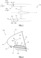
- turbomachine 100 extending along an axis X and comprising a fan 110 rotatably mounted about the axis X in a nacelle comprising an inner shroud 112 in order to accelerate an air flow F from upstream to downstream. Subsequently, the terms upstream and downstream are defined with respect to the circulation of the air flow F.
- the turbomachine 100 comprises at its upstream end an air inlet 102 which makes it possible to separate the incoming air flow F into an internal air flow FINT which is accelerated by the fan 110 and an external air flow FEXT which is guided externally to the nacelle.
- the air inlet 102 comprises an upstream portion 102a, known to those skilled in the art under the designation of lip 102a, and a downstream portion 102b.
- the lip 102a is separated from the downstream portion 102b by an internal partition 125.
- the lip 102a comprises an inner wall 121 facing the axis X and an outer wall 122 which is opposite the inner wall 121, the walls 121, 122 are connected by an upstream wall 123 so as to form an annular cavity 120.
- the lip 102a makes it possible to separate the incoming air flow F into an interior air flow FINT guided by the interior wall 121 and an exterior air flow FEXT guided by the exterior wall 122. Subsequently, the terms interior and exterior are defined radially relative to the axis X of the turbomachine 100.
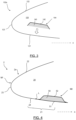
- a lip 102a equipped with an acoustic device 104 comprises a rear skin 142 on which is fixed an acoustic material 140, in particular, honeycomb.
- the rear skin 142 is fixed to the acoustic material 140 by brazing.
- the acoustic device 104 is positioned in the annular cavity 120 on the inner surface of the inner wall 121 of the lip 102a.
- the fixing of the rear skin 142 of the acoustic device 104 to the internal surface of the inner wall 121 of the lip 102a is carried out by brazing using an alloy of the 6061 type which is compatible with the inner wall 121 which is generally made of aluminum to withstand defrosting temperatures.
- Such a brazing step reduces the mechanical characteristics of the inner wall 121. Also, it is necessary to increase its thickness to allow good mechanical strength, which increases the mass of the lip 102a. In fact, the geometric manufacturing tolerances of the acoustic device 104 and the lip 102a make assembly complex. In addition, during cooling following brazing, the inner wall 121 is likely to deform. Furthermore, during brazing, the lip 102a must be placed in a brazing furnace which is likely to cause the outer wall 122 to collapse during heating. In addition, it is necessary to provide specific and complex tooling to hold the acoustic device 104 and the lip 102a together during brazing. Finally, the machining of the acoustic orifices in the inner wall 121 is complex because these must be precisely aligned with cells of the acoustic material 140 in order to ensure optimal acoustic treatment.
- One of the objectives of the invention is to facilitate the manufacture of an air inlet lip comprising an annular acoustic device while having a reduced manufacturing cost.
- a lip 102a it is known to equip a lip 102a with a defrosting system in order to prevent the accumulation of frost on the inner wall 121.
- a hot air injector 103 in the annular cavity 120 and to form blowing openings 130 in the inner wall 121, preferably upstream of the acoustic device 104 in order to heat the inner wall 121.
- the machining of such blowing openings 130 is long and complex to carry out.
- Another object of the invention is to facilitate the manufacture of an air inlet lip comprising such blowing openings.
- US2012048389A1 And US2012241249A1 teach an air inlet comprising an acoustic attenuation member located downstream of the air inlet lip, that is to say, outside the annular cavity.
- US2002139899A1 teaches an air inlet lip without blowing openings.
- the invention relates to an air inlet lip of an aircraft turbomachine nacelle according to claim 1.
- the lip comprises two add-on modules that are assembled together.
- Such a modular design makes it easier to maintain and process the modules since their bulk is limited and can be achieved with simpler and less expensive equipment.
- the risk of defects is limited because it is easier to check the modules that are accessible on each of their faces.
- a modular assembly makes it possible to use various assembly solutions without affecting the health of the modules.
- the mechanical characteristics of the inner wall are preserved and it is no longer likely to deform.
- the outer wall is also preserved.
- the second acoustic module can be simply replaced in the event of a defect.
- the front skin has acoustic perforations. This advantageously allows the internal air flow to penetrate into the acoustic device.
- the second module comprises a rear skin, the acoustic device being housed between the front skin and the rear skin.
- the acoustic device is thus radially sandwiched.
- the front wall of the first module is radially inner to the front skin of the second module at an interface zone between the front wall and the front skin. This advantageously allows a radial connection in the superposition zone.
- Such a blowing opening allows the inner wall of the lip to be defrosted.
- the blowing opening is positioned upstream of the acoustic device in order to allow defrosting of the front skin during circulation of the interior air flow.
- the lip comprises at least one blow opening formed at the interface between the front wall of the first module and the front skin of the second module.
- a blow opening advantageously makes it possible to avoid machining the front wall, which improves its mechanical strength.
- the blow opening is formed at the interface during assembly.
- the front wall of the first module is radially spaced from the front skin of the second module so as to form at least one blowing opening between them.
- the blowing opening advantageously comprises a guide channel which makes it possible to precisely guide the flow of hot defrosting air.
- the lip comprises a filling member housed between the front wall of the first module and the front skin of the second module, that is to say, in the guide channel of the blowing opening.
- the front wall of the first module is radially spaced from the front skin of the second module by at least one spacer pad.
- a spacer pad makes it possible to define the radial thickness of the blowing opening.
- the spacer pad has an aerodynamic shape so as to guide an air flow into the blowing opening.
- the spacer pad comprises a guide opening for a mechanical connecting member configured to secure the front wall of the first module to the front skin of the second module.
- the spacer pad has an aerodynamic profile so as to optimally guide the defrosting air flow. In particular, it makes it possible to avoid the appearance of turbulence due to the mechanical connecting members.
- the lip comprises at least one internal partition mounted between the first module and the second module in the annular cavity, preferably between the internal surface of the outer wall of the first module and the internal surface of the rear skin of the second module. The mounting of such an internal partition is facilitated.
- the annular cavity comprises at least one injector of a hot air flow in order to allow defrosting by blowing via the blowing opening.
- the invention also relates to an air inlet for an aircraft comprising a lip as presented above.
- the air inlet comprises an upstream portion, formed by the lip, and a downstream portion on which the lip is mounted.
- the invention also relates to a turbomachine for an aircraft comprising a nacelle comprising an air inlet as presented previously.
- the invention also relates to a method of manufacturing an air inlet lip according to claim 5.
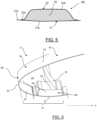
- an air inlet 2 of a nacelle of an aircraft turbomachine according to an embodiment of the invention, in particular, a turbojet nacelle.
- the turbomachine extends along an axis X and allows the circulation, during a thrust, of an air flow from upstream to downstream. Subsequently, the axis X is oriented from upstream to downstream.
- the air inlet 2 comprises an upstream part 2a, known to those skilled in the art under the designation of lip 2a, and a downstream part 2b. In this example, the lip 2a is separated from the downstream part 2b by an internal partition 25.
- the lip 2a extends annularly around the axis X and comprises an inner wall 21 facing the axis X and an outer wall 22 which is opposite the inner wall 21.
- the walls 21, 22 are connected by an upstream wall 23 so as to delimit an annular cavity 20.
- the lip 2a makes it possible to separate the incoming air flow into an inner air flow guided by the inner wall 21 and an outer air flow guided by the outer wall 22. Subsequently, the terms inner and outer are defined radially relative to the axis X of the turbomachine.
- the lip 2a comprises an annular acoustic device 50 mounted in the annular cavity 20.
- the lip 2a comprises a first module M1, comprising the outer wall 22, the upstream wall 23 and a front wall 24 which forms an upstream portion of the inner wall 21.
- the lip 2a further comprises a second module M2, comprising the acoustic device 50 and a front skin 51 which forms a downstream portion of the inner wall 21, the first module M1 and the second module M2 being secured together so that the front wall 24 and the front skin 51 together form the inner wall 21 of the lip 2a.
- the inner wall 21 has an aerodynamic shape to optimally guide the air flow in the secondary vein of the turbomachine.
- a modular inner wall 21 comprising a front wall 24, forming an upstream part, and a front skin 51, forming a downstream part, which are secured during assembly.
- a modular design makes it possible to form a second acoustic module M2 independently, which makes it easier to manufacture it and limits the risk of defects during assembly.
- the first module M1 also referred to as the main module M1
- the main module M1 has a structure similar to the prior art except that it does not have a long inner wall but only a shortened inner wall called the front wall 24.
- the main module M1 is made of a metallic material, preferably resistant to high temperatures, for example, aluminum. Several embodiments of a main module M1 will be presented later.
- the first module M1 is preferably a single-piece.
- the first module M1 is produced by forming (by explosion or other) or by flow forming.
- the second module M2 also referred to as acoustic module M2
- the acoustic device 50 comprises a plurality of acoustic cells, preferably metallic.
- the acoustic device 50 could be in other forms.
- the second module M2 comprises a front skin 51 and a rear skin 52 between which the acoustic device 50 is mounted.
- the front skin 51 of the second acoustic module M2 is configured to extend in the extension of the front wall 24 of the first module M1.
- the front skin 51 is preferably made of a metallic material, in particular, aluminum.
- the front skin 51 comprises a plurality of perforations so as to put the acoustic device 50 in communication with the air flow circulating internally to the lip 2a.
- the perforations can be made before or after assembly of the second module M2.
- the perforations can be made before or after assembly of the modules M1, M2.
- the rear skin 52 defines a concavity in which the acoustic device 50 is housed.
- the rear skin 52 is preferably made of a metallic material, in particular aluminum.
- the acoustic device 50 is secured to the rear skin 52, preferably by brazing.
- the rear skin 52 comprises a concave central portion 52b and two end portions 52a which are secured to the front skin 51.
- a securing is simple to implement since it is carried out independently of the first module M1.
- the rear skin 52 is secured to the front skin 51 by brazing, welding or the like or by mechanical assembly.
- the second module M2 has a reduced size, which facilitates its brazing and assembly in a furnace.
- the mechanical properties of the first module M1 are advantageously not affected.
- the ends 51a of the front skin 51 are longer than those of the rear skin 52 so as to be secured to the first module M1 as will be presented later.
- the second module M2 can be stored, handled and used independently of the first module M1, which significantly simplifies the logistics and assembly of the lip 2a.
- the first module M1 and the second module M2 can be obtained by different methods.
- the modules M1, M2 are manufactured independently and then assembled together.
- the assembly is preferably carried out mechanically, by welding (laser, friction, electron beam, etc.) or the like.
- the air inlet 2 comprises an internal partition 25 so as to form a closed annular cavity 20 in which a flow of defrosting air can circulate in particular.
- the internal partition 25 is mounted between the outer wall 22 of the first module M1 and the rear skin 52 of the second module M2.
- Such a design is advantageous given that it makes it possible, on the one hand, to maximize the dimensions of the acoustic device 50 and, on the other hand, to facilitate the mounting of the internal partition 25 which can be previously mounted on the first module M1 or on the second module M2.
- the acoustic device 50 could be independent of the internal partition 25 and spaced apart from the latter, in particular, the internal partition 25 could be located downstream of the acoustic device 50.
- the air inlet 2 comprises an upstream part 2a and a downstream part 2b.
- the lip 2a can be mounted to a downstream part 2b in order to form the air inlet 2.
- the downstream part 2b comprises an acoustic device.
- the acoustic device of the downstream part 2b is independent of the acoustic device 50 of the lip 2a.
- the acoustic device extends continuously between the downstream part 2b and the lip 2a in order to allow optimal acoustic attenuation.
- An internal partition 25 has been presented between the lip 2a and the downstream part 2b of the air inlet 2 but this is optional.
- the annular cavity 20 comprises at least one injector of a hot air flow, in particular for defrosting the lip 2a.
- the lip 2a comprises at least one blowing opening in the inner wall 21, preferably a plurality of blowing openings in order to guide the hot air flow out of the annular cavity 20 and thus defrost the inner wall 21.
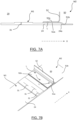
- blowing openings will now be presented with reference to the Figures 7A to 11B .
- the first module M1 and the second M2 are secured together at an interface zone in which one end 51a of the front skin 51 of the second module M2 is secured to the front wall 24 of the first module M1.
- the front skin 51 is radially inside the front wall 24 of the first module M1 so as to allow a connection in a radial direction, for example, by welding or mechanical connection.
- three connections L are shown in the Figure 7B .
- the front skin 51 of the second module M2 is curved so as to comprise an end portion 51a superimposed on the front wall 24 of the first module M1 to allow fixing and a central portion 51b in the extension of the front wall 24 of the first module M1 as illustrated in FIG. Figure 7A .
- the downstream end 24a of the front wall 24 is beveled so as to match the curvature of the front skin 51 of the second module M2, its radially outer surface being radially converging inwards in a direction from upstream to downstream.
- a bevel is simple to produce and avoids significant deformation of the front skin 51 in order to maintain an aerodynamic profile.
- the bevel thus faces a curvature of the front skin 51 in order to obtain a continuous inner wall 21.
- the front wall 24 of the first module M1 comprises a plurality of blowing openings 31 which are formed at a distance from the downstream end of the front wall 24.
- the blowing openings 31 extend substantially radially in the material of the front wall 24.
- Such an independent blowing opening 31 is known to those skilled in the art by its English designation “separated slot”.
- each blowing opening 31 is in this example in the form of an azimuthal direction slot. It goes without saying that the shape and direction could be different.
- the blowing openings 31 are formed in the first module M1 independently of the second module M2. With reference to the Figure 7A , the blowing openings 31 are formed in an excess thickness of the front wall 24, such excess thickness however not being necessary.
- the first module M1 and the second module M2 are secured together at an interface zone in which the end 51a of the front skin 51 of the second module M2 is secured to the front wall 24 of the first module M1.
- the front skin 51 is radially inside the front wall 24 of the first module M1 so as to allow securing in a radial direction.
- the front wall 24 and the front skin 51 are spaced apart radially by a plurality of spacer studs 6, or shims, mounted between the front wall 24 and the front skin 51.
- at least one spacer stud 6 comprises a radial passage opening for guiding a mechanical connecting member L, for example, a rivet.
- a spacer stud 6 has a radial thickness of between 1 mm and 8 mm in order to form a guide channel of calibrated thickness.
- the radial thickness depends on the desired defrosting conditions (temperature, pressure, etc.)
- the blowing opening 32 is here formed at the interface zone during assembly. The mechanical stresses in the front wall 24 of the first module M1 are then limited.
- Such an offset blowing opening 32 is known to those skilled in the art by its English designation “step down slot”. In this example, the blowing opening 32 is circumferential.
- the inner wall 21 of the lip 2a has a radial discontinuity due to the spacing between the front wall 24 and the front skin 51.
- the downstream end 24a of the front wall 24 is beveled, its radially inner surface being convergent radially outwards in a direction from upstream to downstream.
- Such a bevel is simple to produce and significantly limits the aerodynamic discontinuities at the interface between the front wall 24 and the front skin 51. Good performance is obtained for a bevel angle ⁇ less than 15° as illustrated in Figure 8C .
- the radially inner surface is curved to form an aerodynamic profile.
- the front skin 51 of the second module M2 is curved so as to comprise an end portion 51a facing the front wall 24 of the first module M1 to allow radial fixing and a central portion 51b in the extension of the front wall 24 of the first module M1.
- the front wall 24 and the front skin 51 have substantially the same shape as in the first embodiment but are spaced apart radially in a manner similar to the second embodiment, in particular, by spacer pads 6 (not shown in the figure 9 ) and appears in the form of an annular slot.
- a blowing opening 33 is formed here at the interface zone during assembly.
- the blowing opening 33 comprises a guide channel extending longitudinally between the front wall 24 and the front skin 51 so as to guide the flow of hot air.
- the blowing opening 33 opens at the interface between the front wall 24 and the front skin 51 which are aligned.
- Such a buried blowing opening 33 is known to those skilled in the art by its English designation “burried slot”.
- the blowing opening 33 is circumferential.
- a filling member 7 can advantageously be provided in the guide channel so as to act on the flow of hot air before its evacuation.
- the filling member 7 may comprise elementary channels in order to separate the hot air flow into a plurality of elementary flows so as to promote guidance and allow optimal defrosting.
- the filling member 7 comprises a corrugated panel sandwiched between two circumferential panels. More preferably, the filling member 7 is made of metallic material.
- the lip 2a comprises spacer pads 6' having an aerodynamic profile so as to define a leading edge oriented upstream and a trailing edge oriented downstream.
- a spacer pad 6' has a water drop shape as illustrated in Figures 11A and 11B whose section increases then decreases from upstream to downstream. It goes without saying, however, that each spacer organ could have a different shape.
- the spacer pads 6, 6' (with an aerodynamic or non-aerodynamic profile) can be mounted in an attached manner between the front wall 24 and the front skin 51 but can also be made from the material of the front wall 24 or the front skin 51.
- the spacer pads 6, 6' are made from the material of the front wall 24 and formed during the production of the first module M1.
- a modular design makes it easier to maintain and process the modules M1, M2 since their size is limited and can be achieved with simpler and less expensive equipment.
- the risk of defect is limited because the modules M1, M2 are accessible on each of their faces, which facilitates their inspection.
- a modular assembly makes it possible to use various assembly solutions without affecting the health of the modules M1, M2.
- the mechanical characteristics of the inner wall 21 are preserved and it is no longer likely to deform.
- the outer wall 22 is also preserved since it is no longer introduced into a brazing furnace.
- the second acoustic module M2 can be simply replaced in the event of a defect.
Landscapes
- Engineering & Computer Science (AREA)
- Chemical & Material Sciences (AREA)
- Combustion & Propulsion (AREA)
- Aviation & Aerospace Engineering (AREA)
- Mechanical Engineering (AREA)
- General Engineering & Computer Science (AREA)
- Structures Of Non-Positive Displacement Pumps (AREA)
Claims (5)
- Lippe (2a) eines Lufteinlasses (2) einer Flugzeugtriebwerksgondel, die sich entlang einer Achse X erstreckt, in der ein Luftstrom von stromaufwärts nach stromabwärts zirkuliert, wobei sich die Lippe (2a) ringförmig um die Achse X erstreckt und eine innere Wand (21), die der Achse X zugewandt ist, und eine äußere Wand (22), die der inneren Wand (21) gegenüberliegt, wobei die innere Wand (21) und die äußere Wand (22) durch eine stromaufwärts liegende Wand (23) verbunden sind, um einen ringförmigen Hohlraum (20) zu definieren, wobei die Lippe (2a) eine ringförmige akustische Vorrichtung (50) umfasst, die in dem ringförmigen Hohlraum (20) angebracht ist, wobei die Lippe (2a) Folgendes umfasst:- ein erstes Modul (M1), das die Außenwand (22), die stromaufwärts liegende Wand (23) und eine Vorderwand (24) umfasst, die einen stromaufwärts liegenden Teil der Innenwand (21) bildet, und- ein zweites Modul (M2), das die akustische Vorrichtung (50) und eine einen stromabwärts liegenden Abschnitt der Innenwand (21) bildende Vorderhaut (51) aufweist, wobei das erste Modul (M1) und das zweite Modul (M2) so aneinander befestigt sind, dass die Vorderwand (24) und die Vorderhaut (51) zusammen die Innenwand (21) der Lippe (2a) bilden, wobei die Vorderwand (24) des ersten Moduls (M1) von der Vorderhaut (51) des zweiten Moduls (M2) durch mindestens eine Abstandsnase (6, 6') radial getrennt ist, um dazwischen mindestens eine Ausblasöffnung (32, 33) zu bilden, wobei die Lippe (2a) dadurch gekennzeichnet ist, dass die Vorderwand (24) des ersten Moduls (M1) in einem Grenzbereich zwischen der Vorderwand (24) und der Vorderhaut (51) radial innen zur Vorderhaut (51) des zweiten Moduls (M2) liegt.
- Lufteinlasslippe (2a) des Lufteinlasses (2) nach Anspruch 1, wobei das zweite Modul (M2) eine Rückwand (52) umfasst, wobei die akustische Vorrichtung (50) zwischen der Vorderwand (51) und der Rückwand (52) untergebracht ist.
- Lufteinlasslippe (2a) des Lufteinlasses (2) nach einem der Ansprüche 1 bis 2, wobei die Abstandsnase (6') eine aerodynamische Form aufweist, um einen Luftstrom in die Einblasöffnung (33) zu leiten.
- Lufteinlasslippe (2a) des Lufteinlasses (2) nach einem der Ansprüche 1 bis 3, wobei die Abstandsnase (6, 6') eine Führungsöffnung für ein mechanisches Verbindungselement (L) aufweist, das zur Befestigung der Stirnwand (24) des ersten Moduls (M1) an der Vorderhaut (51) des zweiten Moduls (M2) ausgebildet ist.
- Verfahren zur Herstellung einer Lufteinlasslippe (2a) eines Lufteinlasses (2) nach einem der Ansprüche 1 bis 4, umfassend einen Schritt der unabhängigen Herstellung des ersten Moduls (M1) und des zweiten Moduls (M2) und einen Schritt der Befestigung des ersten Moduls (M1) und des zweiten Moduls (M2), so dass die Vorderwand (24) und die Vorderhaut (51) zusammen die Innenwand (21) der Lippe (2a) bilden.
Applications Claiming Priority (2)
| Application Number | Priority Date | Filing Date | Title |
|---|---|---|---|
| FR1905563A FR3096662B1 (fr) | 2019-05-27 | 2019-05-27 | Lèvre d’entrée d’air de nacelle de turbomachine comprenant un dispositif acoustique et procédé de fabrication d’une telle lèvre |
| PCT/EP2020/063536 WO2020239470A1 (fr) | 2019-05-27 | 2020-05-14 | Lèvre d'entrée d'air de nacelle de turbomachine comprenant un dispositif acoustique et procédé de fabrication d'une telle lèvre |
Publications (2)
| Publication Number | Publication Date |
|---|---|
| EP3976476A1 EP3976476A1 (de) | 2022-04-06 |
| EP3976476B1 true EP3976476B1 (de) | 2024-11-13 |
Family
ID=67999852
Family Applications (1)
| Application Number | Title | Priority Date | Filing Date |
|---|---|---|---|
| EP20724859.2A Active EP3976476B1 (de) | 2019-05-27 | 2020-05-14 | Lufteinlasslippe einer turbinentriebwerksgondel und herstellungsverfahren einer solchen lippe |
Country Status (5)
| Country | Link |
|---|---|
| US (1) | US20220212809A1 (de) |
| EP (1) | EP3976476B1 (de) |
| CN (1) | CN113891835B (de) |
| FR (1) | FR3096662B1 (de) |
| WO (1) | WO2020239470A1 (de) |
Families Citing this family (1)
| Publication number | Priority date | Publication date | Assignee | Title |
|---|---|---|---|---|
| US12397915B2 (en) * | 2022-09-02 | 2025-08-26 | General Electric Company | Ice protection systems for aircraft fueled by hydrogen |
Family Cites Families (18)
| Publication number | Priority date | Publication date | Assignee | Title |
|---|---|---|---|---|
| US5088277A (en) * | 1988-10-03 | 1992-02-18 | General Electric Company | Aircraft engine inlet cowl anti-icing system |
| FR2820716B1 (fr) * | 2001-02-15 | 2003-05-30 | Eads Airbus Sa | Procede de degivrage par circulation forcee d'un fluide, d'un capot d'entree d'air de moteur a reaction et dispositif pour sa mise en oeuvre |
| GB0211800D0 (en) * | 2002-05-22 | 2002-07-03 | Short Brothers Plc | An ice protection system for aircraft structures |
| FR2917067B1 (fr) * | 2007-06-08 | 2009-08-21 | Airbus France Sas | Revetement pour le traitement acoustique integrant la fonction de traitement du givre avec de l'air chaud |
| FR2924409B1 (fr) * | 2007-12-03 | 2010-05-14 | Airbus France | Nacelle d'aeronef comprenant des moyens d'evacuations d'air chaud |
| FR2924407B1 (fr) * | 2007-12-03 | 2010-05-14 | Airbus France | Systeme de sortie d'air pour un bord d'attaque d'aeronef |
| EP2391542B1 (de) * | 2009-02-02 | 2014-07-30 | Airbus Operations (S.A.S.) | Triebwerksverkleidung mit lärmschutzvorrichtung |
| FR2954281B1 (fr) * | 2009-12-22 | 2012-04-06 | Airbus Operations Sas | Panneau pour le traitement acoustique a epaisseur evolutive |
| US8234869B2 (en) * | 2010-08-09 | 2012-08-07 | Yen Tuan | Aviation engine inlet with tangential blowing for buzz saw noise control |
| FR2976709B1 (fr) * | 2011-06-20 | 2013-07-12 | Airbus Operations Sas | Procede de realisation d'un panneau pour le traitement acoustique integrant des canaux juxtaposes a une structure alveolaire |
| FR2980776B1 (fr) * | 2011-10-03 | 2014-08-22 | Airbus Operations Sas | Nacelle d'aeronef comportant un panneau pour le traitement acoustique integrant des canaux d'air chaud et au moins un canal annulaire |
| FR2980775B1 (fr) * | 2011-10-03 | 2014-07-11 | Airbus Operations Sas | Nacelle d'aeronef comportant un panneau pour le traitement acoustique integrant des canaux d'air chaud et au moins une chambre de stabilisation |
| FR2980774B1 (fr) * | 2011-10-03 | 2013-10-25 | Airbus Operations Sas | Nacelle d'aeronef comportant un dispositif d'alimentation en air chaud d'un panneau combinant les traitements acoustique et du givre |
| FR3023538B1 (fr) | 2014-07-11 | 2016-07-15 | Aircelle Sa | Levre avant de nacelle de turboreacteur comportant des percages d’air chaud en amont de panneaux acoustiques |
| FR3041937B1 (fr) * | 2015-10-05 | 2017-10-20 | Airbus Operations Sas | Structure compartimentee pour le traitement acoustique et le degivrage d'une nacelle d'aeronef et nacelle d'aeronef incorporant ladite structure |
| US10221765B2 (en) * | 2016-08-26 | 2019-03-05 | Honeywell International Inc. | Anti-icing exhaust system |
| FR3055612B1 (fr) * | 2016-09-06 | 2022-03-04 | Airbus Operations Sas | Structure compartimentee pour le traitement acoustique et le degivrage d'une nacelle d'aeronef et nacelle d'aeronef incorporant ladite structure |
| US20210163141A1 (en) * | 2019-11-28 | 2021-06-03 | Pratt & Whitney Canada Corp. | Gas turbine engine, nacelle thereof, and associated method of operating a gas turbine engine |
-
2019
- 2019-05-27 FR FR1905563A patent/FR3096662B1/fr active Active
-
2020
- 2020-05-14 EP EP20724859.2A patent/EP3976476B1/de active Active
- 2020-05-14 WO PCT/EP2020/063536 patent/WO2020239470A1/fr not_active Ceased
- 2020-05-14 CN CN202080039083.9A patent/CN113891835B/zh active Active
- 2020-05-14 US US17/614,148 patent/US20220212809A1/en not_active Abandoned
Also Published As
| Publication number | Publication date |
|---|---|
| CN113891835B (zh) | 2025-07-18 |
| WO2020239470A1 (fr) | 2020-12-03 |
| FR3096662A1 (fr) | 2020-12-04 |
| CN113891835A (zh) | 2022-01-04 |
| EP3976476A1 (de) | 2022-04-06 |
| US20220212809A1 (en) | 2022-07-07 |
| FR3096662B1 (fr) | 2022-08-12 |
Similar Documents
| Publication | Publication Date | Title |
|---|---|---|
| EP2821597B1 (de) | Trennkante mit Blech zur Bildung einer Fläche zur Strömungsleitung und eines Enteisungskanals | |
| EP3295010B1 (de) | Zwischengehäusenabe für ein flugzeugturbodüsentriebwerk mit einem verbundauslassrohr | |
| EP0898063A1 (de) | Geräuschdämpfungseinrichtung für ein Mantelstromtriebwerk | |
| EP4240956B1 (de) | Anordnung für eine turbomaschine | |
| EP4355983B1 (de) | Nicht ummantelte leitschaufelanordnung einer turbomaschine, modul einer turbomaschine und turbomaschine eines flugzeugs | |
| EP3064708A1 (de) | Verbundwerkstoffschaufel eines kompressors eines axialen turbotriebwerks mit einem verstäkungsblech und zugehörige turbomachine mit solch einer schaufel | |
| FR2956875A1 (fr) | Aube allegee pour turbomachine, carter comportant une pluralite d'une telle aube et turbomachine comportant au moins un tel carter | |
| EP1327489A1 (de) | Verfahren zum Herstellen einer Rillenstruktur und durch dieses Verfahren hergestellte Struktur | |
| EP3959138B1 (de) | Gondellufteinlass und gondel mit einem solchen lufteinlass | |
| WO2025027257A1 (fr) | Aubage fixe de turbomachine comprenant des aubes à calage variable | |
| EP3976476B1 (de) | Lufteinlasslippe einer turbinentriebwerksgondel und herstellungsverfahren einer solchen lippe | |
| EP3473813A1 (de) | Turbotriebwerk, das eine gleichausrichtungsanordnung umfasst | |
| EP3673154B1 (de) | Abblaskanal einer zwischengehäusenabe für ein flugzeugturbostrahltriebwerk mit kühlkanälen | |
| WO2021048323A1 (fr) | Organe de tuyère extérieur pour turbomachine | |
| FR2990928A1 (fr) | Nacelle de moteur a turbine a gaz | |
| FR3133593A1 (fr) | Entrée d’air pour nacelle d’une turbomachine d’aéronef et procédé de montage d’une entrée d’air | |
| EP3610133B1 (de) | Turbinenschaufel mit verbesserter struktur | |
| WO2015001258A1 (fr) | Procédé de réparation d'un panneau par application d'un doubleur | |
| EP4232694B1 (de) | Luftstromrichtstufe für eine turbomaschine | |
| WO2020216712A1 (fr) | Entrée d'air de nacelle à panneau acoustique | |
| FR3034131A1 (fr) | Etage d'aubes de stator pour une turbomachine | |
| FR2998330A1 (fr) | Moyeu de carter pour turbomachine d'aeronef comprenant une piece de fonderie compacte a deflecteur integre au flasque aval | |
| BE1026460B1 (fr) | Carter structural pour turbomachine axiale | |
| WO2025078775A1 (fr) | Tuyere d'ejection de flux d'air a structure interne demontable et turbomachine equipee d'une telle tuyere | |
| WO2025078774A1 (fr) | Tuyere d'ejection de flux d'air a section de sortie constante et turbomachine equipee d'une telle tuyere |
Legal Events
| Date | Code | Title | Description |
|---|---|---|---|
| STAA | Information on the status of an ep patent application or granted ep patent |
Free format text: STATUS: UNKNOWN |
|
| STAA | Information on the status of an ep patent application or granted ep patent |
Free format text: STATUS: THE INTERNATIONAL PUBLICATION HAS BEEN MADE |
|
| PUAI | Public reference made under article 153(3) epc to a published international application that has entered the european phase |
Free format text: ORIGINAL CODE: 0009012 |
|
| STAA | Information on the status of an ep patent application or granted ep patent |
Free format text: STATUS: REQUEST FOR EXAMINATION WAS MADE |
|
| 17P | Request for examination filed |
Effective date: 20211108 |
|
| AK | Designated contracting states |
Kind code of ref document: A1 Designated state(s): AL AT BE BG CH CY CZ DE DK EE ES FI FR GB GR HR HU IE IS IT LI LT LU LV MC MK MT NL NO PL PT RO RS SE SI SK SM TR |
|
| DAV | Request for validation of the european patent (deleted) | ||
| DAX | Request for extension of the european patent (deleted) | ||
| STAA | Information on the status of an ep patent application or granted ep patent |
Free format text: STATUS: EXAMINATION IS IN PROGRESS |
|
| 17Q | First examination report despatched |
Effective date: 20221207 |
|
| GRAP | Despatch of communication of intention to grant a patent |
Free format text: ORIGINAL CODE: EPIDOSNIGR1 |
|
| STAA | Information on the status of an ep patent application or granted ep patent |
Free format text: STATUS: GRANT OF PATENT IS INTENDED |
|
| INTG | Intention to grant announced |
Effective date: 20240322 |
|
| GRAJ | Information related to disapproval of communication of intention to grant by the applicant or resumption of examination proceedings by the epo deleted |
Free format text: ORIGINAL CODE: EPIDOSDIGR1 |
|
| STAA | Information on the status of an ep patent application or granted ep patent |
Free format text: STATUS: EXAMINATION IS IN PROGRESS |
|
| GRAP | Despatch of communication of intention to grant a patent |
Free format text: ORIGINAL CODE: EPIDOSNIGR1 |
|
| STAA | Information on the status of an ep patent application or granted ep patent |
Free format text: STATUS: GRANT OF PATENT IS INTENDED |
|
| INTC | Intention to grant announced (deleted) | ||
| INTG | Intention to grant announced |
Effective date: 20240731 |
|
| GRAS | Grant fee paid |
Free format text: ORIGINAL CODE: EPIDOSNIGR3 |
|
| GRAA | (expected) grant |
Free format text: ORIGINAL CODE: 0009210 |
|
| STAA | Information on the status of an ep patent application or granted ep patent |
Free format text: STATUS: THE PATENT HAS BEEN GRANTED |
|
| AK | Designated contracting states |
Kind code of ref document: B1 Designated state(s): AL AT BE BG CH CY CZ DE DK EE ES FI FR GB GR HR HU IE IS IT LI LT LU LV MC MK MT NL NO PL PT RO RS SE SI SK SM TR |
|
| REG | Reference to a national code |
Ref country code: GB Ref legal event code: FG4D Free format text: NOT ENGLISH |
|
| REG | Reference to a national code |
Ref country code: CH Ref legal event code: EP |
|
| REG | Reference to a national code |
Ref country code: DE Ref legal event code: R096 Ref document number: 602020041275 Country of ref document: DE |
|
| REG | Reference to a national code |
Ref country code: IE Ref legal event code: FG4D Free format text: LANGUAGE OF EP DOCUMENT: FRENCH |
|
| REG | Reference to a national code |
Ref country code: LT Ref legal event code: MG9D |
|
| REG | Reference to a national code |
Ref country code: NL Ref legal event code: MP Effective date: 20241113 |
|
| PG25 | Lapsed in a contracting state [announced via postgrant information from national office to epo] |
Ref country code: HR Free format text: LAPSE BECAUSE OF FAILURE TO SUBMIT A TRANSLATION OF THE DESCRIPTION OR TO PAY THE FEE WITHIN THE PRESCRIBED TIME-LIMIT Effective date: 20241113 Ref country code: PT Free format text: LAPSE BECAUSE OF FAILURE TO SUBMIT A TRANSLATION OF THE DESCRIPTION OR TO PAY THE FEE WITHIN THE PRESCRIBED TIME-LIMIT Effective date: 20250313 Ref country code: IS Free format text: LAPSE BECAUSE OF FAILURE TO SUBMIT A TRANSLATION OF THE DESCRIPTION OR TO PAY THE FEE WITHIN THE PRESCRIBED TIME-LIMIT Effective date: 20250313 |
|
| PG25 | Lapsed in a contracting state [announced via postgrant information from national office to epo] |
Ref country code: FI Free format text: LAPSE BECAUSE OF FAILURE TO SUBMIT A TRANSLATION OF THE DESCRIPTION OR TO PAY THE FEE WITHIN THE PRESCRIBED TIME-LIMIT Effective date: 20241113 Ref country code: NL Free format text: LAPSE BECAUSE OF FAILURE TO SUBMIT A TRANSLATION OF THE DESCRIPTION OR TO PAY THE FEE WITHIN THE PRESCRIBED TIME-LIMIT Effective date: 20241113 |
|
| REG | Reference to a national code |
Ref country code: AT Ref legal event code: MK05 Ref document number: 1741515 Country of ref document: AT Kind code of ref document: T Effective date: 20241113 |
|
| PG25 | Lapsed in a contracting state [announced via postgrant information from national office to epo] |
Ref country code: BG Free format text: LAPSE BECAUSE OF FAILURE TO SUBMIT A TRANSLATION OF THE DESCRIPTION OR TO PAY THE FEE WITHIN THE PRESCRIBED TIME-LIMIT Effective date: 20241113 |
|
| PG25 | Lapsed in a contracting state [announced via postgrant information from national office to epo] |
Ref country code: ES Free format text: LAPSE BECAUSE OF FAILURE TO SUBMIT A TRANSLATION OF THE DESCRIPTION OR TO PAY THE FEE WITHIN THE PRESCRIBED TIME-LIMIT Effective date: 20241113 |
|
| PG25 | Lapsed in a contracting state [announced via postgrant information from national office to epo] |
Ref country code: NO Free format text: LAPSE BECAUSE OF FAILURE TO SUBMIT A TRANSLATION OF THE DESCRIPTION OR TO PAY THE FEE WITHIN THE PRESCRIBED TIME-LIMIT Effective date: 20250213 |
|
| PG25 | Lapsed in a contracting state [announced via postgrant information from national office to epo] |
Ref country code: AT Free format text: LAPSE BECAUSE OF FAILURE TO SUBMIT A TRANSLATION OF THE DESCRIPTION OR TO PAY THE FEE WITHIN THE PRESCRIBED TIME-LIMIT Effective date: 20241113 Ref country code: LV Free format text: LAPSE BECAUSE OF FAILURE TO SUBMIT A TRANSLATION OF THE DESCRIPTION OR TO PAY THE FEE WITHIN THE PRESCRIBED TIME-LIMIT Effective date: 20241113 Ref country code: GR Free format text: LAPSE BECAUSE OF FAILURE TO SUBMIT A TRANSLATION OF THE DESCRIPTION OR TO PAY THE FEE WITHIN THE PRESCRIBED TIME-LIMIT Effective date: 20250214 |
|
| PG25 | Lapsed in a contracting state [announced via postgrant information from national office to epo] |
Ref country code: PL Free format text: LAPSE BECAUSE OF FAILURE TO SUBMIT A TRANSLATION OF THE DESCRIPTION OR TO PAY THE FEE WITHIN THE PRESCRIBED TIME-LIMIT Effective date: 20241113 |
|
| PG25 | Lapsed in a contracting state [announced via postgrant information from national office to epo] |
Ref country code: RS Free format text: LAPSE BECAUSE OF FAILURE TO SUBMIT A TRANSLATION OF THE DESCRIPTION OR TO PAY THE FEE WITHIN THE PRESCRIBED TIME-LIMIT Effective date: 20250213 |
|
| PG25 | Lapsed in a contracting state [announced via postgrant information from national office to epo] |
Ref country code: SM Free format text: LAPSE BECAUSE OF FAILURE TO SUBMIT A TRANSLATION OF THE DESCRIPTION OR TO PAY THE FEE WITHIN THE PRESCRIBED TIME-LIMIT Effective date: 20241113 |
|
| PGFP | Annual fee paid to national office [announced via postgrant information from national office to epo] |
Ref country code: DE Payment date: 20250519 Year of fee payment: 6 |
|
| PG25 | Lapsed in a contracting state [announced via postgrant information from national office to epo] |
Ref country code: DK Free format text: LAPSE BECAUSE OF FAILURE TO SUBMIT A TRANSLATION OF THE DESCRIPTION OR TO PAY THE FEE WITHIN THE PRESCRIBED TIME-LIMIT Effective date: 20241113 |
|
| PGFP | Annual fee paid to national office [announced via postgrant information from national office to epo] |
Ref country code: GB Payment date: 20250527 Year of fee payment: 6 |
|
| PG25 | Lapsed in a contracting state [announced via postgrant information from national office to epo] |
Ref country code: EE Free format text: LAPSE BECAUSE OF FAILURE TO SUBMIT A TRANSLATION OF THE DESCRIPTION OR TO PAY THE FEE WITHIN THE PRESCRIBED TIME-LIMIT Effective date: 20241113 |
|
| PGFP | Annual fee paid to national office [announced via postgrant information from national office to epo] |
Ref country code: FR Payment date: 20250526 Year of fee payment: 6 |
|
| PG25 | Lapsed in a contracting state [announced via postgrant information from national office to epo] |
Ref country code: RO Free format text: LAPSE BECAUSE OF FAILURE TO SUBMIT A TRANSLATION OF THE DESCRIPTION OR TO PAY THE FEE WITHIN THE PRESCRIBED TIME-LIMIT Effective date: 20241113 |
|
| PG25 | Lapsed in a contracting state [announced via postgrant information from national office to epo] |
Ref country code: SK Free format text: LAPSE BECAUSE OF FAILURE TO SUBMIT A TRANSLATION OF THE DESCRIPTION OR TO PAY THE FEE WITHIN THE PRESCRIBED TIME-LIMIT Effective date: 20241113 |
|
| PG25 | Lapsed in a contracting state [announced via postgrant information from national office to epo] |
Ref country code: CZ Free format text: LAPSE BECAUSE OF FAILURE TO SUBMIT A TRANSLATION OF THE DESCRIPTION OR TO PAY THE FEE WITHIN THE PRESCRIBED TIME-LIMIT Effective date: 20241113 |
|
| PG25 | Lapsed in a contracting state [announced via postgrant information from national office to epo] |
Ref country code: IT Free format text: LAPSE BECAUSE OF FAILURE TO SUBMIT A TRANSLATION OF THE DESCRIPTION OR TO PAY THE FEE WITHIN THE PRESCRIBED TIME-LIMIT Effective date: 20241113 |
|
| REG | Reference to a national code |
Ref country code: DE Ref legal event code: R097 Ref document number: 602020041275 Country of ref document: DE |
|
| PG25 | Lapsed in a contracting state [announced via postgrant information from national office to epo] |
Ref country code: SE Free format text: LAPSE BECAUSE OF FAILURE TO SUBMIT A TRANSLATION OF THE DESCRIPTION OR TO PAY THE FEE WITHIN THE PRESCRIBED TIME-LIMIT Effective date: 20241113 |
|
| PLBE | No opposition filed within time limit |
Free format text: ORIGINAL CODE: 0009261 |
|
| STAA | Information on the status of an ep patent application or granted ep patent |
Free format text: STATUS: NO OPPOSITION FILED WITHIN TIME LIMIT |
|
| 26N | No opposition filed |
Effective date: 20250814 |
|
| REG | Reference to a national code |
Ref country code: CH Ref legal event code: H13 Free format text: ST27 STATUS EVENT CODE: U-0-0-H10-H13 (AS PROVIDED BY THE NATIONAL OFFICE) Effective date: 20251223 |
|
| PG25 | Lapsed in a contracting state [announced via postgrant information from national office to epo] |
Ref country code: LU Free format text: LAPSE BECAUSE OF NON-PAYMENT OF DUE FEES Effective date: 20250514 |
|
| PG25 | Lapsed in a contracting state [announced via postgrant information from national office to epo] |
Ref country code: CH Free format text: LAPSE BECAUSE OF NON-PAYMENT OF DUE FEES Effective date: 20250531 |
|
| REG | Reference to a national code |
Ref country code: BE Ref legal event code: MM Effective date: 20250531 |
|
| PG25 | Lapsed in a contracting state [announced via postgrant information from national office to epo] |
Ref country code: MC Free format text: LAPSE BECAUSE OF FAILURE TO SUBMIT A TRANSLATION OF THE DESCRIPTION OR TO PAY THE FEE WITHIN THE PRESCRIBED TIME-LIMIT Effective date: 20241113 |
|
| PG25 | Lapsed in a contracting state [announced via postgrant information from national office to epo] |
Ref country code: IE Free format text: LAPSE BECAUSE OF NON-PAYMENT OF DUE FEES Effective date: 20250514 |
|
| PG25 | Lapsed in a contracting state [announced via postgrant information from national office to epo] |
Ref country code: BE Free format text: LAPSE BECAUSE OF NON-PAYMENT OF DUE FEES Effective date: 20250531 |