EP3976216B1 - Beutelanordnung - Google Patents
Beutelanordnung Download PDFInfo
- Publication number
- EP3976216B1 EP3976216B1 EP20730694.5A EP20730694A EP3976216B1 EP 3976216 B1 EP3976216 B1 EP 3976216B1 EP 20730694 A EP20730694 A EP 20730694A EP 3976216 B1 EP3976216 B1 EP 3976216B1
- Authority
- EP
- European Patent Office
- Prior art keywords
- pouch
- valve
- assembly
- upper layer
- illumination device
- Prior art date
- Legal status (The legal status is an assumption and is not a legal conclusion. Google has not performed a legal analysis and makes no representation as to the accuracy of the status listed.)
- Active
Links
Images

Classifications
-
- A—HUMAN NECESSITIES
- A63—SPORTS; GAMES; AMUSEMENTS
- A63H—TOYS, e.g. TOPS, DOLLS, HOOPS OR BUILDING BLOCKS
- A63H27/00—Toy aircraft; Other flying toys
- A63H27/10—Balloons
-
- A—HUMAN NECESSITIES
- A63—SPORTS; GAMES; AMUSEMENTS
- A63H—TOYS, e.g. TOPS, DOLLS, HOOPS OR BUILDING BLOCKS
- A63H33/00—Other toys
- A63H33/001—Toy-moulding appliances; Toy moulding
-
- B—PERFORMING OPERATIONS; TRANSPORTING
- B29—WORKING OF PLASTICS; WORKING OF SUBSTANCES IN A PLASTIC STATE IN GENERAL
- B29D—PRODUCING PARTICULAR ARTICLES FROM PLASTICS OR FROM SUBSTANCES IN A PLASTIC STATE
- B29D22/00—Producing hollow articles
- B29D22/02—Inflatable articles
-
- F—MECHANICAL ENGINEERING; LIGHTING; HEATING; WEAPONS; BLASTING
- F21—LIGHTING
- F21V—FUNCTIONAL FEATURES OR DETAILS OF LIGHTING DEVICES OR SYSTEMS THEREOF; STRUCTURAL COMBINATIONS OF LIGHTING DEVICES WITH OTHER ARTICLES, NOT OTHERWISE PROVIDED FOR
- F21V33/00—Structural combinations of lighting devices with other articles, not otherwise provided for
- F21V33/008—Leisure, hobby or sport articles, e.g. toys, games or first-aid kits; Hand tools; Toolboxes
-
- A—HUMAN NECESSITIES
- A63—SPORTS; GAMES; AMUSEMENTS
- A63B—APPARATUS FOR PHYSICAL TRAINING, GYMNASTICS, SWIMMING, CLIMBING, OR FENCING; BALL GAMES; TRAINING EQUIPMENT
- A63B41/00—Hollow inflatable balls
-
- A—HUMAN NECESSITIES
- A63—SPORTS; GAMES; AMUSEMENTS
- A63B—APPARATUS FOR PHYSICAL TRAINING, GYMNASTICS, SWIMMING, CLIMBING, OR FENCING; BALL GAMES; TRAINING EQUIPMENT
- A63B43/00—Balls with special arrangements
- A63B43/06—Balls with special arrangements with illuminating devices ; with reflective surfaces
-
- A—HUMAN NECESSITIES
- A63—SPORTS; GAMES; AMUSEMENTS
- A63H—TOYS, e.g. TOPS, DOLLS, HOOPS OR BUILDING BLOCKS
- A63H27/00—Toy aircraft; Other flying toys
- A63H27/10—Balloons
- A63H2027/1025—Fabrication methods or special materials therefor
-
- A—HUMAN NECESSITIES
- A63—SPORTS; GAMES; AMUSEMENTS
- A63H—TOYS, e.g. TOPS, DOLLS, HOOPS OR BUILDING BLOCKS
- A63H27/00—Toy aircraft; Other flying toys
- A63H27/10—Balloons
- A63H2027/1058—Balloons associated with light or sound
-
- A—HUMAN NECESSITIES
- A63—SPORTS; GAMES; AMUSEMENTS
- A63H—TOYS, e.g. TOPS, DOLLS, HOOPS OR BUILDING BLOCKS
- A63H27/00—Toy aircraft; Other flying toys
- A63H27/10—Balloons
- A63H2027/1083—Valves or nozzles
-
- A—HUMAN NECESSITIES
- A63—SPORTS; GAMES; AMUSEMENTS
- A63H—TOYS, e.g. TOPS, DOLLS, HOOPS OR BUILDING BLOCKS
- A63H27/00—Toy aircraft; Other flying toys
- A63H27/10—Balloons
- A63H2027/1091—Balloons with object inserted within; Means or methods for insertion of objects
-
- F—MECHANICAL ENGINEERING; LIGHTING; HEATING; WEAPONS; BLASTING
- F21—LIGHTING
- F21Y—INDEXING SCHEME ASSOCIATED WITH SUBCLASSES F21K, F21L, F21S and F21V, RELATING TO THE FORM OR THE KIND OF THE LIGHT SOURCES OR OF THE COLOUR OF THE LIGHT EMITTED
- F21Y2115/00—Light-generating elements of semiconductor light sources
- F21Y2115/10—Light-emitting diodes [LED]
Definitions
- the present invention relates to a pouch assembly for use in an inflatable toy, an array of pouch assemblies, and an inflatable toy having the pouch assembly; and to methods relating thereto.
- An inflatable toy can be formed of a flexible material that is inflatable with a gas, e.g. air or helium.
- a gas e.g. air or helium.
- inflatable toys include, e.g. balloons, balls and lilos.
- the illumination device is inserted and sealed in the inflatable toy (to render the illumination device inaccessible to an end user and facilitate accordance with toy safety regulations, e.g. European Standard EN 71) whilst the inflatable toy is being manufactured.
- a problem with this approach is that once the inflatable toy having the illumination device has been manufactured, it is not possible to access the illumination device from the exterior of the inflatable toy.
- Another problem with this approach is that bespoke/specialist manufacturing equipment is required to insert and seal the illumination device in the inflatable toy, which increases manufacturing costs.
- Another problem in the prior art is that different manufacturing equipment is required to manufacture inflatable toys having different illumination devices, which also increases manufacturing costs.
- the illumination device and the means of retaining the illumination device in the inflatable toy add to the total weight, which can be impractical and therefore less desirable.
- the inflatable toy is a balloon that is inflated with a low-density gas (e.g. helium)
- the additional weight of the illumination device and the means of retaining the illumination device can make it more difficult for the balloon to float.
- a known solution to this problem is to increase the total inflatable volume of the balloon, so that when the balloon is inflated with a low-density gas, the additional inflatable volume provides sufficient buoyancy for the balloon to float.
- increasing the inflatable volume of the balloon can mean that more gas is required to inflate the balloon, which increases costs.
- US6602105B1 discloses a balloon illumination system comprising a pair of thin film panels that are heat sealed together to define the interior of the balloon and a flat film valve creating a sleeve within the balloon.
- the illumination system further comprises a light source located inside a tube and the tube is inserted through the sleeve to span across the entire balloon and illuminate the balloon.
- US5795211A discloses an inflated non-latex portable balloon with an internal lamp or transducer connected to an external battery.
- a lead is connects the battery to the lamp via the neck of the balloon which is hermetically sealed by fusing together the lead and balloon panels.
- US5108339A discloses a non-latex inflatable toy comprising an inner balloon encompassed by a partially transparent outer balloon.
- An inflation umbilical extends from the stem of the outer balloon to the inner balloon allowing them both to be inflated.
- US5336123A discloses an inflatable flexible pouch comprising first and second inner webs forming an inner inflatable chamber and first and second outer webs forming an outer inflatable chamber surrounding the inner inflatable chamber.
- the pouch comprises means for inflating the inner chamber until backpressure causes the outer chamber to also inflate.
- a pouch assembly for use in an inflatable toy, the pouch assembly comprising: a pouch comprising a pouch upper layer and a pouch lower layer, the pouch upper layer and the pouch lower layer being sealed together along a first sealing path, wherein the pouch is adapted to receive and retain an illumination device in a predetermined position: wherein the pouch comprises gripping means provided as one or more projections, adapted to retain said m illumination device in a predetermined position.
- the pouch can be accessed after the inflatable toy having the pouch assembly is manufactured, such that an illumination device can be incorporated into the inflatable toy after the inflatable toy has been manufactured.
- the inflatable toy having the pouch assembly can be first manufactured, and then the illumination device can be inserted into the pouch and sealed therein (i.e. two-step manufacture of the inflatable device having the illumination device).
- the inflatable toy can be manufactured using standard manufacturing equipment rather than specialist/bespoke equipment (since the illumination device can be later inserted and sealed therein), which can reduce manufacturing costs.
- the pouch can be sealed in order that an illumination device retained in the pouch is inaccessible to an end user, to facilitate accordance with toy safety regulations (e.g. European Standard EN 71).
- an illumination device can be easily and conveniently installed in the inflatable toy relative to inflatable toys of the prior art.
- the pouch also helps secure an illumination device in the inflatable toy, such that the illumination device is less prone to becoming dislodged.
- the assembly provides a single unit for receiving and retaining an illumination device in an inflatable toy by way of the pouch, which can help reduce the total volume and weight of the inflatable toy.
- the inflatable toy is a balloon having the assembly
- the balloon being inflated by a low-density gas (e.g. a floating balloon)
- the balloon can be manufactured to a smaller inflatable volume (whilst having sufficient buoyancy to float when inflated and fitted with an illumination device) relative to balloons of the prior art (which must have a relatively large inflatable volume).
- a balloon having the assembly of the invention can be manufactured to a wide range of sizes relative to balloon of the prior art. Cost savings can therefore be attained by manufacturing smaller balloons which require less gas for inflation.
- the inflatable toy may be any suitable inflatable toy as are known to a person skilled in the art.
- inflatable toys include but are not limited to balloons, balls and lilos.
- balloons include but are not limited to simple shaped balloons or complex shaped balloons.
- simple shaped balloons include but are not limited to geometric shapes, e.g. spheres, ellipsoids, ovoids or polyhedrons.
- complex shaped balloons include but are not limited to imitation objects, e.g. imitation swords.
- the inflatable toy may be formed of a heat-sealable material.
- the inflatable toy may comprise one or more of polyethylene, polypropylene, polyester, nylon, polyvinyl chloride, cellulose acetate and cellophane.
- the inflatable toy may consist essentially of polyethylene.
- the inflatable toy may comprise low-density polyethylene.
- the inflatable toy may consist essentially of low-density polyethylene.
- low-density polyethylene can be easily heat sealed, and is readily available and inexpensive.
- the inflatable toy may comprise one or more sheets.
- the inflatable toy may be formed of plastics material.
- the inflatable toy may be metallised.
- the illumination device may be any suitable illumination device as are known to a person skilled in the art.
- the illumination device may comprise an illumination element operable to emit light.
- the illumination element may be a lamp or a light emitting diode (LED).
- the illumination device may comprise a printed circuit board (PCB).
- the PCB may be flexible.
- the illumination device may comprise a battery arranged in electronic communication with the illumination element by an electronic circuit.
- the illumination device may comprise a switch operable to switch the illumination device on or off.
- the switch may be a button switch.
- the switch may form part of the electronic circuit.
- the illumination device may comprise a pull tab arranged to prevent electrical connection between the battery and the illumination element.
- a pull tab is advantageous for preventing drainage of battery power.
- the pull tab may be arranged between electrical contacts in the circuit so as to prevent flow of electrical charge.
- the pull tab may be removable from the electrical contacts so as to permit electrical connection between the battery and the illumination element. In use, the pull tab may be accessed from the outside of the inflatable toy.
- the illumination device may be an LED strip light (also known as an LED tape or ribbon light).
- the illumination device may comprise a communications unit.
- communications units include but are not limited to Bluetooth devices, GPS devices and Wi-Fi devices.
- the illumination device may comprise a processor operable to process information.
- the information may be control signals received by the communications unit.
- the illumination device may comprise output means.
- output means include but are not limited to audio output means and video output means.
- the illumination device may comprise haptic feedback means.
- haptic feedback means include but are not limited to vibration means.
- the pouch may be adapted to receive and retain an illumination device therein. This can obscure the physical components of the illumination device from view, and thereby improves compactness and tamper resistance.
- the pouch may be adapted to receive and retain a switch of an illumination device therein.
- the pouch may be adapted to receive and retain an illumination element of an illumination device therein.
- the pouch may be delimited by the first sealing path, the pouch upper layer and the pouch lower layer.
- the gripping means may be adapted to retain a switch of an illumination device in a predetermined position.
- the projections may be curved or straight.
- the gripping means may be provided as one or more projections formed by the first sealing path.
- the gripping means can help securely retain an illumination device in the pouch.
- the pouch may comprise an opening through which an illumination device can be inserted.
- the opening may be provided at one end of the pouch and an opposite end of the pouch may be closed.
- the pouch assembly may be arranged so that the pouch can form a vacuous seal around an illumination device retained therein.
- the pouch may project into the interior of an inflatable toy.
- the assembly may comprise an inflation valve.
- the assembly may be an inflation valve and pouch assembly for use in an inflatable toy.
- the inflation valve can facilitate inflation and deflation of an inflatable toy having the assembly.
- an inflatable toy having the assembly can be more lightweight, compact and better balanced relative to inflatable toys of the prior art in which the means of retaining an illumination device in the inflatable toy and the inflation valve are provided in separate openings at separate locations.
- the inflation valve may be a balloon valve.
- the valve may comprise a valve inlet and a valve outlet.
- the valve inlet may be provided at one end of the valve and the valve outlet may be provided at an opposite end of the valve.
- air may be directed through the valve inlet and out of the valve outlet, into the inflatable toy; and to deflate the inflatable toy, air may be directed through the valve outlet and out of the valve inlet, out of the inflatable toy.
- the valve may be self-sealing.
- the internal pressure of the inflatable toy can seal the valve.
- the valve may comprise a valve upper layer and a valve lower layer.
- the valve upper layer and the valve lower layer may be sealed together along a second sealing path.
- the valve may be delimited by the second sealing path, the valve upper layer and the valve lower layer.
- the pouch may be arranged adjacent to or on the valve.
- the valve inlet may be arranged proximal to the pouch opening.
- the valve outlet may be arranged proximal to the closed end of the pouch. In this way, the valve inlet and pouch inlet are conveniently positioned (i.e. close to one another) and easily accessible.
- the first sealing path and/or the second sealing path may be formed by any suitable sealing process.
- the first sealing path and/or the second sealing path may be formed by heat-sealing. Suitable heat-sealing methods are known to a person skilled in the art.
- the assembly may be provided with one or more heat-resistant patches.
- the heat-resistant patches are operable to prevent the occurrence of heat sealing (e.g. during a heat-sealing process) in desired locations on the assembly. In this way, where heat sealing is used on the assembly, the heat sealing can be accurately localised such that the specific shape and dimensions of the valve and/or pouch can be controlled.
- the valve and/or the pouch may be provided with one or more heat-resistant patches.
- the valve upper layer and/or the valve lower layer may be provided with one or more heat-resistant patches.
- the pouch upper layer and/or the pouch lower layer may be provided with one or more heat-resistant patches.
- Each of the valve upper layer, the valve lower layer, the pouch upper layer and the pouch lower layer may be provided with one or more heat-resistant patches.
- the or each heat resistant patch may be provided in any suitable shape for a particular application.
- the or each heat-resistant patch may comprise heat-resistant ink.
- the assembly may be formed of any suitable material as will be known to a person skilled in the art.
- the assembly may be formed of a heat-sealable material.
- the assembly may comprise one or more of polyethylene, polypropylene, polyester, nylon, polyvinyl chloride, cellulose acetate and cellophane.
- the assembly may consist essentially of polyethylene.
- the assembly may comprise low-density polyethylene.
- the assembly may consist essentially of low-density polyethylene.
- low-density polyethylene can be easily heat sealed, and is readily available and inexpensive.
- the assembly may be formed from a single film.
- the total thickness of the assembly may be from 100 to 160 microns. Total thicknesses below 100 microns can result in lower product performance, and total thicknesses above 160 microns can result in manufacturing difficulties.
- each of the valve upper layer and/or the valve lower layer and/or the pouch upper layer and/or the pouch lower layer may be from 25 to 40 microns. Thicknesses below 25 microns can result in lower product performance, and thicknesses above 40 microns can result in manufacturing difficulties.
- an array of pouch assemblies for use in an inflatable toy comprising a plurality of pouch assemblies according to the first aspect of the present invention, wherein the pouch assemblies are connected together.
- the array can be used to quickly and conveniently prepare a plurality of inflatable toys each having a assembly. This results in more efficient inflatable toy manufacture.
- the assemblies may be connected together side-by-side.
- Each assembly may be separated from another assembly by an assembly cut line.
- respective assemblies can be separated (i.e. individualised) by cutting along the assembly cut line.
- an inflatable toy comprising a pouch assembly according to the first aspect of the present invention, wherein the assembly is mounted in a neck of the inflatable toy.
- the assembly may be mounted in the neck of the inflatable toy using any suitable means.
- the assembly may be mounted in the neck of the inflatable toy by sealing means (e.g. heat-sealing).
- the inflatable toy may comprise an illumination device.
- the illumination device may be received and retained in the pouch in a predetermined position.
- the inflatable toy comprises the assembly and an illumination device is retained in the pouch, the illumination device comprising a pull tab
- the assembly allows external control of the lighting of the inflatable toy via the pull tab. In this way, the lighting of the inflatable toy can be controlled externally of the inflatable toy without damaging the sealing of the inflatable toy.
- a method of manufacturing a pouch assembly for use in an inflatable toy comprising a pouch, wherein the pouch is adapted to receive and retain an illumination device in a predetermined position, the method comprising the steps of:
- the assembly can be efficiently manufactured in terms of physical requirements and/or cost.
- Step (a) may further comprise providing a valve upper layer and valve lower layer.
- Step (b) may further comprise sealing together the valve upper layer and the valve lower layer to form an inflatable toy valve.
- the method may be a method of manufacturing an inflatable toy valve and pouch assembly for use in an inflatable toy.
- step (a) at least one of the pouch upper layer, the pouch lower layer, where present the valve upper layer and where present the valve lower layer may be provided with one or more heat-resistant patches.
- the heat-resistant patches are operable to prevent heat sealing (e.g. during a heat-sealing process) at desired locations on the assembly. In this way, when heat sealing is used on the assembly, the heat sealing can be accurately localised such that the specific shape and dimensions of the valve and/or pouch can be controlled.
- each of the pouch upper layer, the pouch lower layer, where present the valve upper layer and where 2. present the valve upper layer and where present the valve lower layer may be provided with one or more heat-resistant patches.
- Each heat-resistant patch may comprise heat-resistant ink.
- the pouch upper layer, the pouch lower layer, where present the valve upper layer and where present the valve lower layer may be provided on a single film. In this way, the assembly can be more efficiently manufactured relative to known methods wherein multiple separate films are used.
- the pouch upper layer may be connected to the pouch lower layer by a pouch fold line.
- the pouch lower layer may be connected to the valve upper layer by an intermediate cut line.
- the valve upper layer may be connected to the valve lower layer by a valve fold line.
- a ⁇ fold line' constitutes a region along which respective layers can be folded.
- a ⁇ cut line' constitutes a region along which respective layers can be folded and separated by cutting.
- step (b) the sealing may be achieved using any suitable sealing means.
- the sealing is heat-sealing. Suitable heat-sealing methods are well known to a person skilled in the art.
- step (b) the pouch upper layer and the pouch lower layer may be sealed together along a first sealing path to define the pouch.
- valve upper layer and the valve lower layer may be sealed together along a second sealing path to define the valve.
- the method may comprise, after step (a) and before step (b), cutting the intermediate cut line to separate the pouch lower layer from the valve upper layer.
- the method may comprise, after step (a) and before step (b), folding along the valve fold line so that the valve upper layer is arranged on the valve lower layer.
- the method may comprise, after step (a) and before step (b), folding along the pouch fold line so that the pouch upper layer is arranged on the pouch lower layer.
- the method may comprise, after forming the valve and the pouch (i.e. in step (c)), cutting off an end of the valve towards the fold line, such that the valve is open at both ends.
- the method may comprise, after forming the valve and the pouch (i.e. in step (c)), sealing the valve to the pouch. In this way the valve and pouch form an integrated unit. This prevents the valve and pouch from separating.
- the sealing may be heat-sealing.
- the method may comprise, after step (b) or step (c) (i.e. in step (d)), inserting an illumination device into the pouch.
- the method may comprise, after step (b) or step (c) or step (d) (i.e. in step (e)), arranging the assembly in inflatable toy material; optionally cutting the inflatable toy material to shape; and sealing the assembly in the inflatable toy material.
- the method may be a method of manufacturing an inflatable toy.
- the method may comprise, after step (b) or step (c) or step (d) or step (e), sealing the inflatable toy material around the illumination device such that the illumination device is securely retained in the inflatable toy. This renders the illumination device inaccessible and can facilitate accordance with European Standard EN 71.
- the inflatable toy material may be provided with marking lines.
- the marking lines facilitate alignment of the inflatable toy material.
- the method may comprise, after step (b) or step (c), holding the assembly and the inflatable toy material together using holding means. This can help align the assembly and the inflatable toy material before and during sealing.
- the holding means may be applied electrostatic attraction. The electrostatic attraction may be applied on the assembly and/or the inflatable toy material.
- step (a) comprises providing respective pouch upper layers, pouch lower layers, where present valve upper layers and where present valve lower layers; and step (b) comprises sealing together the pouch upper layers and the pouch lower layers to form respective pouches, and where present the valve upper layers and where present the valve lower layers to form respective valves.
- the assemblies may be connected together, side-by-side.
- the assemblies may be provided on a single film.
- the respective assemblies may be separated by assembly cut lines.
- the assembly cut lines can be cut to individualise (i.e. separate) the assemblies.
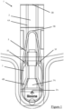
- a balloon valve and pouch assembly 1 is mounted in a neck portion of a balloon and comprises a balloon valve 2 and a pouch 3.
- the pouch 3 is adapted to receive and retain an illumination device 100 in a predetermined position.
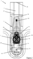
- the illumination device 100 comprises a battery (not shown), an electrical circuit (now shown), a button switch 101 operable to switch the device on or off, a light emitting diode (LED) as an illumination element 102 operable to emit light when the device is switched on, and a removable pull tab 103 configured to prevent electrical connection between the battery and the illumination element 102.
- the pull tab 103 is arranged between electrical contacts in the electrical circuit and prevents flow of electrical charge and thus illumination of the illumination element 102; and can be removed from the electrical contacts to permit flow of electrical charge and thus illumination of the illumination element 102. The pull tab prevents inadvertent drainage of battery power.
- the valve 2 has a valve inlet 2A and a valve outlet 2B.
- the valve inlet 2A is provided at one end of the valve 2 and the valve outlet 2B is provided at an opposite end of the valve 2.
- the valve 2 comprises a valve upper layer 2C and a valve lower layer 2D.
- the layers 2C, 2D are heat-sealed together along a second sealing path 4, which includes a substantially rectangular portion 4A adjoining a substantially funnel-shaped potion 4B.
- the funnel-shaped portion 4B is arranged towards the valve inlet 2A and the rectangular portion 4A terminates towards the valve outlet 2B.
- the valve 2 is self-sealing.
- the valve 2 is delimited by the second sealing path 4 and the layers 2C, 2D.
- the pouch 3 comprises an opening 3A through which an illumination device 100 can be inserted (see Figs. 2 and 5 ).
- the opening 3A is provided at one end of the pouch 3 and an opposite end of the pouch 3B is closed.
- the pouch 3 comprises a pouch upper layer 3C and a pouch lower layer 3D.
- the layers 3C, 3D are heat-sealed together along a first sealing path 5, which is substantially V-shaped, with the open end of the V-shape defining the pouch opening 3A and the closed end of the V-shape defining the closed end of the pouch 3B.
- the pouch 3 is delimited by the first sealing path 5 and the layers 3C, 3D.
- the pouch 3 is arranged on and heat sealed to the valve 2 so that the valve inlet 2A is arranged towards the pouch opening 3A and the valve outlet 2B is arranged towards the closed end 3B of the pouch.
- the pouch 3 comprises two gripping projections 3E, 3F which are adapted to retain the illumination device 100 in a predetermined position.
- the projections 3E, 3F are formed by the first sealing path 5; face radially inwards, towards each other; and project towards the closed end of the V-shape at an oblique angle with respect to the longitudinal axis of the V-shape.
- the projections 3E, 3F contact and support the button switch 101 and thereby help securely retain the illumination device 100 in a predetermined position in the pouch 3.
- the LED illumination element 102 extends between the projections 3E, 3F, towards the closed end of the pouch, and is retained by and within the first sealing path 5 (see Figs. 2 and 5 ).
- the balloon valve and pouch assembly 1 is provided with heat-resistant patches 6A, 6B.
- the heat-resistant patches 6A, 6B comprise heat-resistant ink, which prevents the occurrence of heat-sealing (e.g. see Fig. 3 ).
- the patches 6A are provided on the valve layers 2C, 2D and are substantially torch shaped. Specifically, on each layer 2C, 2D, a patch 6A starts at the funnel-shaped portion of the second sealing path 4 and terminates approximately half-way down the second sealing path 4. On each layer 3C, 3D, a patch 6B is provided towards the pouch opening 3A and another patch 6B is provided between the gripping projections 3E, 3F and towards the closed end 3B of the pouch.
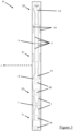
- the layers 2C, 2D, 3C, 3D of the assembly 1 are manufactured from a single low-density polyethylene film 10 having a thickness of about 25 microns.
- the film 10 is provided with printed markings corresponding to respective valve upper layers 2C, valve lower layers 2D, pouch upper layers 3C, pouch lower layers 3D, fold lines 7 connecting each pouch upper layer 3C to its corresponding pouch lower layer 3D, intermediate cut lines 8 connecting each pouch lower layer 3D to its corresponding valve upper layer 2C, valve fold lines 9 connecting each valve upper layer 3C to its corresponding valve lower layer 3D, and optionally markers which provide a visual indication of whether or not the layers 2C, 2D, 3C, 3D are correctly aligned when folded together in position (as detailed below).
- a plurality of printed markings corresponding to respective balloon valve and pouch assemblies are provided side-by-side on the film.
- the longitudinal axes of the printed markings corresponding to the respective balloon valve and pouch assemblies are arranged in parallel to each other.
- a portion of the film is illustrated in Fig. 3 .
- the film 10 includes a plurality of further balloon valve and pouch assemblies 1, connected together side-by-side, extending along axis 'X' as shown in Fig. 3 .
- the film 10 is also provided with heat resistant patches 6A, 6B, which comprise heat-resistant ink.
- the heat resistant patches 6A, 6B prevent the occurrence of heat-sealing in the areas of the film on which the patches 6A, 6B are provided.
- the film 10 is cut along each intermediate cut line 8 so that the valve upper layers 2C are separated from the pouch lower layers 3D.
- the film 10 is folded along the valve fold lines 9 so that the valve upper layers 2C are arranged on the valve lower layers 2D, such that the heat-resistant patches 6A provided on the valve upper layers 2C overlap with the heat-resistant patches 6A provided on the valve lower layers 2D.
- the film 10 is folded along the pouch fold lines 7 so that the pouch upper layers 3C are arranged on the pouch lower layers 3D, such that the heat resistant patches 6B provided on the pouch upper layers 3C overlap with the heat-resistant patches 6B provided on the pouch lower layers 3D.
- valve upper layers 2C are heat sealed to the valve lower layers 2D along second sealing paths 4 to thereby define respective valves 2.
- Each valve 2 is thus delimited by the layers 2C, 2D and its respective second sealing path 4.
- Each valve 2 has a valve inlet 2A and a valve outlet 2B.
- the pouch upper layers 3C are heat sealed to the pouch lower layers 3D along first sealing paths 5 to thereby define respective pouches 3.
- Each pouch 3 is thus delimited by the layers 3C, 3D and its respective first sealing path 5.
- Each pouch 3 has at one end thereof a pouch opening 3A through which an illumination device 100 can be inserted, and at an opposite end thereof 3B is closed.
- the pouches 3 are arranged on the valves 2 so that the pouch lower layers 3D are arranged on the valve upper layers 2C.
- the pouch openings 3A are proximal to the valve inlets 2A and the closed ends 3B of the pouches are proximal to the valve outlets 2B.
- the abovementioned optional markers can be used to align the valves 2 and the pouches 3.
- valves 2 and pouches 3 are heat sealed together at various tacking locations.
- valves 2 towards the fold lines 7 are cut off, so that the valve 2 is open at both ends, the cut-off end defining the valve outlet 2B and the opposite end defining a valve inlet 2A.
- balloon valve and pouch assemblies 1 An array of balloon valve and pouch assemblies 1 is thus manufactured, wherein the respective balloon valve and pouch assemblies 1 are connected together side-by-side.
- the respective balloon valve and pouch assemblies 1 can be individualised using any suitable cutting means.
- a method of manufacturing a foil balloon comprising an assembly 1 according to the present invention is described below.
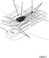
- An illumination device 100 having a button switch 101 and an LED illumination element 102 is inserted through the pouch opening, so that the button switch 101 is retained in the pouch by the gripping projections 3E, 3F and the LED illumination element 102 projects between the gripping projections 3E, 3F towards the closed end 3B of the pouch and is retained by and within the first sealing path 5.
- the assembly 1 With the illumination device 100 received in the assembly 1, the assembly 1 is arranged between two foil sheets of balloon material, which are substantially identical in shape and dimensions.
- the foil sheets are heat-sealed together along their periphery and subsequently cut to shape to form a balloon including a neck portion in which the assembly 1 is mounted.
- the components of the illumination device 100 are obscured from view.
- an electrostatic attractive force may be applied to the assembly 1 and/or the foil sheets of balloon material prior to sealing together the assembly 1 and the foil sheets. This holds in position the assembly 1 and the foil sheets and prevents inadvertent separation thereof.
Landscapes
- Engineering & Computer Science (AREA)
- Mechanical Engineering (AREA)
- Health & Medical Sciences (AREA)
- General Health & Medical Sciences (AREA)
- Physical Education & Sports Medicine (AREA)
- General Engineering & Computer Science (AREA)
- Toys (AREA)
- Arrangement Of Elements, Cooling, Sealing, Or The Like Of Lighting Devices (AREA)
Claims (19)
- Beutelanordnung (1) zur Verwendung in einem aufblasbaren Spielzeug, wobei die Beutelanordnung (1) aufweist: einen Beutel (3), der eine obere Beutelschicht (3C) und eine untere Beutelschicht (3D) aufweist, wobei die obere Beutelschicht (3C) und die untere Beutelschicht (3D) entlang eines ersten Versiegelungsweges (5) miteinander versiegelt sind, wobei der Beutel (3) dazu geeignet ist, eine Beleuchtungsvorrichtung (100) aufzunehmen und in einer vorbestimmten Position zu halten: wobei der Beutel (3) Greifmittel (3E, 3F) aufweist, die als ein oder mehrere Vorsprünge bereitgestellt sind, die dazu geeignet sind, die Beleuchtungsvorrichtung in einer vorbestimmten Position zu halten.
- Anordnung (1) nach Anspruch 1, wobei der Beutel (3) durch den ersten Versiegelungsweg (5), die obere Beutelschicht (3C) und die untere Beutelschicht (3D) begrenzt ist.
- Anordnung (1) nach Anspruch 1 oder 2, wobei der Beutel (3) eine Öffnung (3A) aufweist, durch die eine Beleuchtungsvorrichtung (100) eingesetzt werden kann.
- Anordnung (1) nach einem der vorhergehenden Ansprüche, wobei die Anordnung (1) mit einem oder mehreren hitzebeständigen Abschnitten (6A, 6B) versehen ist.
- Anordnung (1) nach einem der vorhergehenden Ansprüche, wobei die Anordnung (1) aus einem heißsiegelfähigen Material gebildet ist.
- Anordnung (1) nach einem der vorhergehenden Ansprüche, wobei die Anordnung (1) ein Ventil (2) aufweist.
- Anordnung (1) nach Anspruch 6, wobei das Ventil (2) eine obere Ventilschicht (2C) und eine untere Ventilschicht (2D) aufweist, wobei die obere Ventilschicht (2C) und die untere Ventilschicht (2D) entlang eines zweiten Versiegelungsweges (4) miteinander versiegelt sind, so dass das Ventil (2) durch den zweiten Versiegelungsweg (4), die obere Ventilschicht (2C) und die untere Ventilschicht (2D) begrenzt ist.
- Reihe von Beutelanordnungen (1), wobei die Reihe eine Vielzahl von Beutelanordnungen (1) nach einem der vorhergehenden Ansprüche aufweist, wobei die Beutelanordnungen (1) miteinander verbunden sind.
- Aufblasbares Spielzeug, aufweisend eine Beutelanordnung (1) nach einem der Ansprüche 1 bis 8, wobei die Beutelanordnung (1) in einem Hals des aufblasbaren Spielzeugs befestigt ist.
- Aufblasbares Spielzeug nach Anspruch 10, wobei das aufblasbare Spielzeug eine Beleuchtungsvorrichtung (100) aufweist.
- Verfahren zur Herstellung einer Beutelanordnung (1) zur Verwendung in einem aufblasbaren Spielzeug, wobei die Beutelanordnung (1) einen Beutel (3) aufweist, wobei der Beutel (3) dazu geeignet ist, eine Beleuchtungsvorrichtung (100) in einer vorbestimmten Position aufzunehmen und zu halten, wobei das Verfahren die folgenden Schritte umfasst:(a) Bereitstellen einer oberen Beutelschicht (3C) und einer unteren Beutelschicht (3D);(b) Versiegeln der oberen Beutelschicht (3C) und der unteren Beutelschicht (3D) miteinander, um einen Beutel (3) zu bilden, wobei der Versiegelungsschritt dem Beutel (3) auch Greifmittel bereitstellt, die als ein oder mehrere Vorsprünge (3E, 3F) bereitgestellt sind, wobei die Greifmittel dazu geeignet sind, eine Beleuchtungsvorrichtung in einer vorbestimmten Position zu halten
- Verfahren nach Anspruch 11, wobei Schritt (a) weiterhin ein Bereitstellen einer oberen Ventilschicht (2C) und einer unteren Ventilschicht (2D) umfasst, und Schritt (b) weiterhin ein Versiegeln der oberen Ventilschicht (2C) und der unteren Ventilschicht (2D) miteinander zur Bildung eines Ventils (2) umfasst.
- Verfahren nach Anspruch 11 oder 12, wobei in Schritt (a) die obere Beutelschicht(2C), die untere Beutelschicht (2D), wenn vorhanden die obere Ventilschicht (3C) und wenn vorhanden die untere Ventilschicht (3D) auf einer einzigen Folie bereitgestellt werden.
- Verfahren nach einem der Ansprüche 11 bis 13, wobei in Schritt (b) die obere Beutelschicht (2C) und die untere Beutelschicht (2D) entlang eines ersten Versiegelungswegs (5) miteinander versiegelt werden, um den Beutel (3) zu definieren.
- Verfahren nach einem der Ansprüche 11 bis 14, wenn von Anspruch 13 abhängig, wobei in Schritt (b) die obere Ventilschicht (2C) und die untere Ventilschicht (2D) entlang eines zweiten Versiegelungswegs (5) miteinander versiegelt werden, um das Ventil (2) zu definieren.
- Verfahren nach einem der Ansprüche 11 bis 15, wenn von Anspruch 12 abhängig, wobei in Schritt (a) die obere Beutelschicht (3C) mit der unteren Beutelschicht (3D) durch eine Beutelfaltlinie (7) verbunden ist; wobei die untere Beutelschicht (3D) mit der oberen Ventilschicht (2C) durch eine Zwischenschnittlinie (8) verbunden ist; und wobei die obere Ventilschicht (2C) mit der unteren Ventilschicht (2D) durch eine Ventilfaltlinie (9) verbunden ist.
- Verfahren nach einem der Ansprüche 11 bis 16, wobei das Verfahren nach Schritt (b) das Einsetzen einer Beleuchtungsvorrichtung (100) in den Beutel (3) und das Befestigen der Beutelanordnung (1) in einem aufblasbaren Spielzeug umfasst.
- Verfahren nach einem der Ansprüche 11 bis 17, wobei das Verfahren nach Schritt (b) umfasst: ein Anordnen der Beutelanordnung (1) in einem aufblasbarem Spielzeugmaterial; optional ein Zuschneiden des aufblasbaren Spielzeugmaterials; und ein Versiegeln der Anordnung (1) in dem aufblasbaren Spielzeugmaterial.
- Verfahren nach einem der Ansprüche 11 bis 18, wobei das Verfahren die Herstellung einer Reihe von Beutelanordnungen (1) umfasst, wobei Schritt (a) ein Bereitstellen entsprechender oberer Beutelschichten (3C), unterer Beutelschichten (3D), wenn vorhanden oberer Ventilschichten (2C) und wenn vorhanden unterer Ventilschichten (2D) umfasst, und Schritt (b) ein Versiegeln der oberen Beutelschichten (3C) und der unteren Beutelschichten (3D) miteinander umfasst, um entsprechende Beutel (3) zu bilden, und, wenn vorhanden, ein Versiegeln der oberen Ventilschichten (2C) und der unteren Ventilschichten (2D) miteinander, um entsprechende Ventile (2) zu bilden.
Applications Claiming Priority (2)
| Application Number | Priority Date | Filing Date | Title |
|---|---|---|---|
| GB1907746.0A GB2586773B (en) | 2019-05-31 | 2019-05-31 | Pouch assembly |
| PCT/GB2020/051286 WO2020240182A1 (en) | 2019-05-31 | 2020-05-28 | Pouch assembly |
Publications (3)
| Publication Number | Publication Date |
|---|---|
| EP3976216A1 EP3976216A1 (de) | 2022-04-06 |
| EP3976216C0 EP3976216C0 (de) | 2024-12-18 |
| EP3976216B1 true EP3976216B1 (de) | 2024-12-18 |
Family
ID=67385876
Family Applications (1)
| Application Number | Title | Priority Date | Filing Date |
|---|---|---|---|
| EP20730694.5A Active EP3976216B1 (de) | 2019-05-31 | 2020-05-28 | Beutelanordnung |
Country Status (11)
| Country | Link |
|---|---|
| US (1) | US12029995B2 (de) |
| EP (1) | EP3976216B1 (de) |
| JP (1) | JP7595589B2 (de) |
| CN (1) | CN113874089A (de) |
| AU (1) | AU2020284502B2 (de) |
| CA (1) | CA3139792A1 (de) |
| ES (1) | ES3009694T3 (de) |
| GB (1) | GB2586773B (de) |
| HU (1) | HUE070366T2 (de) |
| PL (1) | PL3976216T3 (de) |
| WO (1) | WO2020240182A1 (de) |
Citations (1)
| Publication number | Priority date | Publication date | Assignee | Title |
|---|---|---|---|---|
| GB2472785A (en) * | 2009-08-17 | 2011-02-23 | Mellowgraphic Ltd | Inflatable, non-latex balloon with a self-sealing valve |
Family Cites Families (41)
| Publication number | Priority date | Publication date | Assignee | Title |
|---|---|---|---|---|
| GB199435A (en) * | 1922-03-14 | 1923-06-14 | Harold Falkner Anns | Improvements relating to toy balloons and the like |
| DE8703193U1 (de) * | 1987-03-02 | 1987-07-16 | Neumeier, Robert, 8183 Rottach-Egern | Verschlußkopf für einen Luftballon |
| US4917646A (en) * | 1988-08-17 | 1990-04-17 | Kieves G | Self-sealing valve, a self-sealing, non-latex balloon, and a method for producing such a balloon |
| US5108339A (en) * | 1990-08-22 | 1992-04-28 | Anagram International, Inc. | Non-latex inflatable toy |
| US5188558A (en) * | 1991-01-02 | 1993-02-23 | Barton Leslie W | Self-sealing refillable plastic balloon valve |
| US5144708A (en) * | 1991-02-26 | 1992-09-08 | Dielectrics Industries | Check valve for fluid bladders |
| JPH0513496U (ja) | 1991-08-06 | 1993-02-23 | 株式会社トランスワールドインフオメイシヨンズ | 光を発する風船玩具 |
| US5336123A (en) * | 1992-04-08 | 1994-08-09 | Vonco Products, Inc. | Inflatable flexible pouch |
| US5295892A (en) * | 1992-11-04 | 1994-03-22 | Show-Me Balloons | Balloon having a self sealing valve and method of making same |
| US5860441A (en) * | 1995-11-29 | 1999-01-19 | Convertidora Industries S.A. De C.V. | Self-sealing flexible plastic valve with curled inlet |
| US5795211A (en) * | 1996-01-11 | 1998-08-18 | Satellite Balloon Manufacturer Of Hong Kong Ltd. | Illuminated non-latex balloon |
| US5669702A (en) * | 1996-06-11 | 1997-09-23 | Wang; Wen-Ching | Inflatable article with an illuminating device |
| US5934310A (en) * | 1996-12-31 | 1999-08-10 | Littlehorn; Michael J. | Balloon valve and method of producing |
| US5807157A (en) * | 1997-01-07 | 1998-09-15 | Penjuke; Daniel | Device and method for internally lighting a mylar balloon |
| GB2324480B (en) * | 1997-04-17 | 1999-03-10 | Licinio John Basevi | Self sealing valve cojoined with plastic film balloon |
| US5947581A (en) * | 1997-06-13 | 1999-09-07 | Chemical Light, Inc. | Illuminated balloon having a self-contained light member |
| JP3235988B2 (ja) * | 1998-06-12 | 2001-12-04 | 国雄 駒場 | 紐付き風船及びその製造方法 |
| US6602105B1 (en) * | 1998-10-21 | 2003-08-05 | Michael Sussell | Illumination system for balloons with thin film valves |
| US6155901A (en) * | 1999-02-08 | 2000-12-05 | Chen; David | Light-emitting inflatable envelope structure |
| US20060291217A1 (en) * | 2003-03-11 | 2006-12-28 | Vanderschuit Carl R | Lighted inflated or inflatable objects |
| AU2005252194B2 (en) * | 2004-06-05 | 2011-11-03 | Nguyen, Logan A | Device and method for sealing and lighting a balloon |
| US8292454B2 (en) * | 2004-11-12 | 2012-10-23 | Chemical Light, Inc. | Externally switchable illuminated balloon inflator |
| US20060275565A1 (en) * | 2005-06-03 | 2006-12-07 | Jose De Jesus Michel Velasco | Autoblock valve for non latex type baloons |
| US7476141B2 (en) * | 2006-08-25 | 2009-01-13 | Young Jesse Hom | Toy balloon saber |
| GB2452236A (en) * | 2007-03-09 | 2009-03-04 | Mellowgraphic Ltd | Party balloon with illumination device |
| TWI351820B (en) * | 2007-03-27 | 2011-11-01 | Mstar Semiconductor Inc | Clock generator, method for generating clock signa |
| US20090191787A1 (en) * | 2008-01-26 | 2009-07-30 | Rubinstein David B | LED embedded balloon |
| US20100018879A1 (en) * | 2008-07-23 | 2010-01-28 | Creative Products Enterprises Pty Litmited | Inflatable Hand Beverage Carrier |
| GB201002031D0 (en) * | 2010-02-08 | 2010-03-24 | Seatriever Internat Holdings L | An attachment device |
| TW201215814A (en) * | 2010-10-04 | 2012-04-16 | deng-hui Wu | Illuminating inflatable pouch |
| US20120129420A1 (en) * | 2010-11-22 | 2012-05-24 | Teng-Hui Wu | Light-emitting inflatable balloon |
| CN102366675B (zh) * | 2011-10-14 | 2015-01-14 | 深圳概念贸易有限公司 | 具有照明/发声装置的气球 |
| CN102500114B (zh) * | 2011-10-31 | 2015-01-14 | 深圳概念贸易有限公司 | 用于气球充气启动的照明/发声装置 |
| CN102527057B (zh) * | 2012-01-20 | 2015-01-14 | 深圳概念贸易有限公司 | 具有照明/发声效果的气球充气装置 |
| CN203291515U (zh) * | 2013-05-06 | 2013-11-20 | 胡伟鹏 | 一种气球灯组件及气球组件 |
| US9192872B2 (en) * | 2013-09-05 | 2015-11-24 | Cool Glow LLC | Apparatus for sealing and illuminating a balloon |
| GB201503342D0 (en) * | 2015-02-27 | 2015-04-15 | Seatriever Int Holdings Ltd | Printed display |
| JP3201719U (ja) | 2015-10-13 | 2015-12-24 | 株式会社三洋 | 風船構造体 |
| CN106621366B (zh) * | 2017-03-07 | 2022-07-08 | 佛山市大吉大利科技有限公司 | 一种充气后自动内发光的空气球 |
| JP2020066465A (ja) * | 2018-10-24 | 2020-04-30 | 有限会社岩村包装企画 | 袋体及びスティックバルーン |
| CN110064211A (zh) * | 2019-06-05 | 2019-07-30 | 无锡深梦科技有限公司 | 一种玩具氦气球 |
-
2019
- 2019-05-31 GB GB1907746.0A patent/GB2586773B/en active Active
-
2020
- 2020-05-28 ES ES20730694T patent/ES3009694T3/es active Active
- 2020-05-28 US US17/615,359 patent/US12029995B2/en active Active
- 2020-05-28 EP EP20730694.5A patent/EP3976216B1/de active Active
- 2020-05-28 CN CN202080040020.5A patent/CN113874089A/zh active Pending
- 2020-05-28 JP JP2021570184A patent/JP7595589B2/ja active Active
- 2020-05-28 AU AU2020284502A patent/AU2020284502B2/en active Active
- 2020-05-28 PL PL20730694.5T patent/PL3976216T3/pl unknown
- 2020-05-28 CA CA3139792A patent/CA3139792A1/en active Pending
- 2020-05-28 HU HUE20730694A patent/HUE070366T2/hu unknown
- 2020-05-28 WO PCT/GB2020/051286 patent/WO2020240182A1/en not_active Ceased
Patent Citations (1)
| Publication number | Priority date | Publication date | Assignee | Title |
|---|---|---|---|---|
| GB2472785A (en) * | 2009-08-17 | 2011-02-23 | Mellowgraphic Ltd | Inflatable, non-latex balloon with a self-sealing valve |
Also Published As
| Publication number | Publication date |
|---|---|
| JP2022534903A (ja) | 2022-08-04 |
| PL3976216T3 (pl) | 2025-04-14 |
| CA3139792A1 (en) | 2020-12-13 |
| GB201907746D0 (en) | 2019-07-17 |
| EP3976216C0 (de) | 2024-12-18 |
| AU2020284502B2 (en) | 2025-07-03 |
| GB2586773B (en) | 2024-01-17 |
| GB2586773A (en) | 2021-03-10 |
| AU2020284502A1 (en) | 2021-12-16 |
| US20220226746A1 (en) | 2022-07-21 |
| EP3976216A1 (de) | 2022-04-06 |
| CN113874089A (zh) | 2021-12-31 |
| HUE070366T2 (hu) | 2025-06-28 |
| JP7595589B2 (ja) | 2024-12-06 |
| ES3009694T3 (en) | 2025-03-31 |
| US12029995B2 (en) | 2024-07-09 |
| WO2020240182A1 (en) | 2020-12-03 |
Similar Documents
| Publication | Publication Date | Title |
|---|---|---|
| US5108339A (en) | Non-latex inflatable toy | |
| KR101666698B1 (ko) | 자체밀봉 밸브를 구비하고 팽창가능한 비 라텍스성 풍선 | |
| AU620348B2 (en) | Rolled-up packaging system and method | |
| US5807157A (en) | Device and method for internally lighting a mylar balloon | |
| US5183432A (en) | Floating body of sophisticated shape produced from a single sheet of film with a single sealing | |
| US6520333B1 (en) | Tubular inflatable packaging cushion with product pocket | |
| US5795211A (en) | Illuminated non-latex balloon | |
| JP2010521044A (ja) | 照明装置を有するパーティ風船 | |
| US9296462B1 (en) | Flight termination system for a balloon | |
| EP3242040B1 (de) | Zusammenfaltbares aufblasbares saugsystem | |
| EP2686080B1 (de) | Beleuchteter ballon | |
| US20080311820A1 (en) | Inflatable noisemaker | |
| EP3738656B1 (de) | Aufblasbares dekoratives system | |
| US5772034A (en) | Bag assembly | |
| US6244923B1 (en) | Balloon and a method for manufacturing the balloon | |
| EP3976216B1 (de) | Beutelanordnung | |
| US5399122A (en) | Balloon with accompanying helium supplying cartridge | |
| US6384764B1 (en) | Inflatable radar reflector | |
| WO1997038252A1 (es) | Conformacion de valvula autosellante para globos o articulos no elastomericos mediante un proceso de produccion masiva | |
| US6575805B1 (en) | Non-latex centerpiece balloon | |
| JP2004243111A (ja) | 剛性バルーン | |
| US20030102404A1 (en) | Non-latex balloon and method for producing the same | |
| CN119084916A (zh) | 便携式户外led照明灯 | |
| US20090081917A1 (en) | Combination novelty balloon and bag | |
| JPH0633984Y2 (ja) | 多面体型玩具風船 |
Legal Events
| Date | Code | Title | Description |
|---|---|---|---|
| STAA | Information on the status of an ep patent application or granted ep patent |
Free format text: STATUS: UNKNOWN |
|
| STAA | Information on the status of an ep patent application or granted ep patent |
Free format text: STATUS: THE INTERNATIONAL PUBLICATION HAS BEEN MADE |
|
| PUAI | Public reference made under article 153(3) epc to a published international application that has entered the european phase |
Free format text: ORIGINAL CODE: 0009012 |
|
| STAA | Information on the status of an ep patent application or granted ep patent |
Free format text: STATUS: REQUEST FOR EXAMINATION WAS MADE |
|
| 17P | Request for examination filed |
Effective date: 20211117 |
|
| AK | Designated contracting states |
Kind code of ref document: A1 Designated state(s): AL AT BE BG CH CY CZ DE DK EE ES FI FR GB GR HR HU IE IS IT LI LT LU LV MC MK MT NL NO PL PT RO RS SE SI SK SM TR |
|
| DAV | Request for validation of the european patent (deleted) | ||
| DAX | Request for extension of the european patent (deleted) | ||
| STAA | Information on the status of an ep patent application or granted ep patent |
Free format text: STATUS: EXAMINATION IS IN PROGRESS |
|
| 17Q | First examination report despatched |
Effective date: 20231116 |
|
| GRAP | Despatch of communication of intention to grant a patent |
Free format text: ORIGINAL CODE: EPIDOSNIGR1 |
|
| STAA | Information on the status of an ep patent application or granted ep patent |
Free format text: STATUS: GRANT OF PATENT IS INTENDED |
|
| INTG | Intention to grant announced |
Effective date: 20240710 |
|
| GRAS | Grant fee paid |
Free format text: ORIGINAL CODE: EPIDOSNIGR3 |
|
| GRAA | (expected) grant |
Free format text: ORIGINAL CODE: 0009210 |
|
| STAA | Information on the status of an ep patent application or granted ep patent |
Free format text: STATUS: THE PATENT HAS BEEN GRANTED |
|
| AK | Designated contracting states |
Kind code of ref document: B1 Designated state(s): AL AT BE BG CH CY CZ DE DK EE ES FI FR GR HR HU IE IS IT LI LT LU LV MC MK MT NL NO PL PT RO RS SE SI SK SM TR |
|
| RBV | Designated contracting states (corrected) |
Designated state(s): AL AT BE BG CH CY CZ DE DK EE ES FI FR GR HR HU IE IS IT LI LT LU LV MC MK MT NL NO PL PT RO RS SE SI SK SM TR |
|
| REG | Reference to a national code |
Ref country code: CH Ref legal event code: EP |
|
| REG | Reference to a national code |
Ref country code: DE Ref legal event code: R096 Ref document number: 602020043337 Country of ref document: DE |
|
| REG | Reference to a national code |
Ref country code: IE Ref legal event code: FG4D |
|
| U01 | Request for unitary effect filed |
Effective date: 20250117 |
|
| U07 | Unitary effect registered |
Designated state(s): AT BE BG DE DK EE FI FR IT LT LU LV MT NL PT RO SE SI Effective date: 20250128 |
|
| REG | Reference to a national code |
Ref country code: ES Ref legal event code: FG2A Ref document number: 3009694 Country of ref document: ES Kind code of ref document: T3 Effective date: 20250331 |
|
| PG25 | Lapsed in a contracting state [announced via postgrant information from national office to epo] |
Ref country code: HR Free format text: LAPSE BECAUSE OF FAILURE TO SUBMIT A TRANSLATION OF THE DESCRIPTION OR TO PAY THE FEE WITHIN THE PRESCRIBED TIME-LIMIT Effective date: 20241218 |
|
| PG25 | Lapsed in a contracting state [announced via postgrant information from national office to epo] |
Ref country code: NO Free format text: LAPSE BECAUSE OF FAILURE TO SUBMIT A TRANSLATION OF THE DESCRIPTION OR TO PAY THE FEE WITHIN THE PRESCRIBED TIME-LIMIT Effective date: 20250318 |
|
| PG25 | Lapsed in a contracting state [announced via postgrant information from national office to epo] |
Ref country code: GR Free format text: LAPSE BECAUSE OF FAILURE TO SUBMIT A TRANSLATION OF THE DESCRIPTION OR TO PAY THE FEE WITHIN THE PRESCRIBED TIME-LIMIT Effective date: 20250319 |
|
| PG25 | Lapsed in a contracting state [announced via postgrant information from national office to epo] |
Ref country code: RS Free format text: LAPSE BECAUSE OF FAILURE TO SUBMIT A TRANSLATION OF THE DESCRIPTION OR TO PAY THE FEE WITHIN THE PRESCRIBED TIME-LIMIT Effective date: 20250318 |
|
| REG | Reference to a national code |
Ref country code: HU Ref legal event code: AG4A Ref document number: E070366 Country of ref document: HU |
|
| U20 | Renewal fee for the european patent with unitary effect paid |
Year of fee payment: 6 Effective date: 20250523 |
|
| PG25 | Lapsed in a contracting state [announced via postgrant information from national office to epo] |
Ref country code: SM Free format text: LAPSE BECAUSE OF FAILURE TO SUBMIT A TRANSLATION OF THE DESCRIPTION OR TO PAY THE FEE WITHIN THE PRESCRIBED TIME-LIMIT Effective date: 20241218 |
|
| PGFP | Annual fee paid to national office [announced via postgrant information from national office to epo] |
Ref country code: PL Payment date: 20250523 Year of fee payment: 6 |
|
| PGFP | Annual fee paid to national office [announced via postgrant information from national office to epo] |
Ref country code: ES Payment date: 20250623 Year of fee payment: 6 |
|
| PG25 | Lapsed in a contracting state [announced via postgrant information from national office to epo] |
Ref country code: IS Free format text: LAPSE BECAUSE OF FAILURE TO SUBMIT A TRANSLATION OF THE DESCRIPTION OR TO PAY THE FEE WITHIN THE PRESCRIBED TIME-LIMIT Effective date: 20250418 |
|
| PG25 | Lapsed in a contracting state [announced via postgrant information from national office to epo] |
Ref country code: SK Free format text: LAPSE BECAUSE OF FAILURE TO SUBMIT A TRANSLATION OF THE DESCRIPTION OR TO PAY THE FEE WITHIN THE PRESCRIBED TIME-LIMIT Effective date: 20241218 |
|
| PGFP | Annual fee paid to national office [announced via postgrant information from national office to epo] |
Ref country code: IE Payment date: 20250523 Year of fee payment: 6 |
|
| PLBE | No opposition filed within time limit |
Free format text: ORIGINAL CODE: 0009261 |
|
| STAA | Information on the status of an ep patent application or granted ep patent |
Free format text: STATUS: NO OPPOSITION FILED WITHIN TIME LIMIT |
|
| REG | Reference to a national code |
Ref country code: CH Ref legal event code: L10 Free format text: ST27 STATUS EVENT CODE: U-0-0-L10-L00 (AS PROVIDED BY THE NATIONAL OFFICE) Effective date: 20251029 |
|
| 26N | No opposition filed |
Effective date: 20250919 |
|
| REG | Reference to a national code |
Ref country code: CH Ref legal event code: H13 Free format text: ST27 STATUS EVENT CODE: U-0-0-H10-H13 (AS PROVIDED BY THE NATIONAL OFFICE) Effective date: 20251223 |
|
| PG25 | Lapsed in a contracting state [announced via postgrant information from national office to epo] |
Ref country code: HU Free format text: LAPSE BECAUSE OF NON-PAYMENT OF DUE FEES Effective date: 20250529 |
|
| PG25 | Lapsed in a contracting state [announced via postgrant information from national office to epo] |
Ref country code: CH Free format text: LAPSE BECAUSE OF NON-PAYMENT OF DUE FEES Effective date: 20250531 |
|
| PG25 | Lapsed in a contracting state [announced via postgrant information from national office to epo] |
Ref country code: CZ Free format text: LAPSE BECAUSE OF NON-PAYMENT OF DUE FEES Effective date: 20250528 |
|
| PG25 | Lapsed in a contracting state [announced via postgrant information from national office to epo] |
Ref country code: MC Free format text: LAPSE BECAUSE OF FAILURE TO SUBMIT A TRANSLATION OF THE DESCRIPTION OR TO PAY THE FEE WITHIN THE PRESCRIBED TIME-LIMIT Effective date: 20241218 |