EP3976153B1 - Katheteranordnung mit injektionsöffnung - Google Patents
Katheteranordnung mit injektionsöffnung Download PDFInfo
- Publication number
- EP3976153B1 EP3976153B1 EP20731745.4A EP20731745A EP3976153B1 EP 3976153 B1 EP3976153 B1 EP 3976153B1 EP 20731745 A EP20731745 A EP 20731745A EP 3976153 B1 EP3976153 B1 EP 3976153B1
- Authority
- EP
- European Patent Office
- Prior art keywords
- arm
- divider
- catheter assembly
- catheter
- lumen
- Prior art date
- Legal status (The legal status is an assumption and is not a legal conclusion. Google has not performed a legal analysis and makes no representation as to the accuracy of the status listed.)
- Active
Links
Images


Classifications
-
- A—HUMAN NECESSITIES
- A61—MEDICAL OR VETERINARY SCIENCE; HYGIENE
- A61M—DEVICES FOR INTRODUCING MEDIA INTO, OR ONTO, THE BODY; DEVICES FOR TRANSDUCING BODY MEDIA OR FOR TAKING MEDIA FROM THE BODY; DEVICES FOR PRODUCING OR ENDING SLEEP OR STUPOR
- A61M25/00—Catheters; Hollow probes
- A61M25/0097—Catheters; Hollow probes characterised by the hub
-
- A—HUMAN NECESSITIES
- A61—MEDICAL OR VETERINARY SCIENCE; HYGIENE
- A61M—DEVICES FOR INTRODUCING MEDIA INTO, OR ONTO, THE BODY; DEVICES FOR TRANSDUCING BODY MEDIA OR FOR TAKING MEDIA FROM THE BODY; DEVICES FOR PRODUCING OR ENDING SLEEP OR STUPOR
- A61M5/00—Devices for bringing media into the body in a subcutaneous, intra-vascular or intramuscular way; Accessories therefor, e.g. filling or cleaning devices, arm-rests
- A61M5/14—Infusion devices, e.g. infusing by gravity; Blood infusion; Accessories therefor
-
- A—HUMAN NECESSITIES
- A61—MEDICAL OR VETERINARY SCIENCE; HYGIENE
- A61M—DEVICES FOR INTRODUCING MEDIA INTO, OR ONTO, THE BODY; DEVICES FOR TRANSDUCING BODY MEDIA OR FOR TAKING MEDIA FROM THE BODY; DEVICES FOR PRODUCING OR ENDING SLEEP OR STUPOR
- A61M25/00—Catheters; Hollow probes
- A61M25/0009—Making of catheters or other medical or surgical tubes
- A61M25/0015—Making lateral openings in a catheter tube, e.g. holes, slits, ports, piercings of guidewire ports; Methods for processing the holes, e.g. smoothing the edges
-
- A—HUMAN NECESSITIES
- A61—MEDICAL OR VETERINARY SCIENCE; HYGIENE
- A61M—DEVICES FOR INTRODUCING MEDIA INTO, OR ONTO, THE BODY; DEVICES FOR TRANSDUCING BODY MEDIA OR FOR TAKING MEDIA FROM THE BODY; DEVICES FOR PRODUCING OR ENDING SLEEP OR STUPOR
- A61M25/00—Catheters; Hollow probes
- A61M25/0017—Catheters; Hollow probes specially adapted for long-term hygiene care, e.g. urethral or indwelling catheters to prevent infections
-
- A—HUMAN NECESSITIES
- A61—MEDICAL OR VETERINARY SCIENCE; HYGIENE
- A61M—DEVICES FOR INTRODUCING MEDIA INTO, OR ONTO, THE BODY; DEVICES FOR TRANSDUCING BODY MEDIA OR FOR TAKING MEDIA FROM THE BODY; DEVICES FOR PRODUCING OR ENDING SLEEP OR STUPOR
- A61M25/00—Catheters; Hollow probes
- A61M25/0021—Catheters; Hollow probes characterised by the form of the tubing
- A61M25/0023—Catheters; Hollow probes characterised by the form of the tubing by the form of the lumen, e.g. cross-section, variable diameter
- A61M25/0026—Multi-lumen catheters with stationary elements
-
- A—HUMAN NECESSITIES
- A61—MEDICAL OR VETERINARY SCIENCE; HYGIENE
- A61M—DEVICES FOR INTRODUCING MEDIA INTO, OR ONTO, THE BODY; DEVICES FOR TRANSDUCING BODY MEDIA OR FOR TAKING MEDIA FROM THE BODY; DEVICES FOR PRODUCING OR ENDING SLEEP OR STUPOR
- A61M25/00—Catheters; Hollow probes
- A61M25/01—Introducing, guiding, advancing, emplacing or holding catheters
- A61M25/06—Body-piercing guide needles or the like
- A61M25/0606—"Over-the-needle" catheter assemblies, e.g. I.V. catheters
-
- A—HUMAN NECESSITIES
- A61—MEDICAL OR VETERINARY SCIENCE; HYGIENE
- A61M—DEVICES FOR INTRODUCING MEDIA INTO, OR ONTO, THE BODY; DEVICES FOR TRANSDUCING BODY MEDIA OR FOR TAKING MEDIA FROM THE BODY; DEVICES FOR PRODUCING OR ENDING SLEEP OR STUPOR
- A61M39/00—Tubes, tube connectors, tube couplings, valves, access sites or the like, specially adapted for medical use
- A61M39/02—Access sites
- A61M39/04—Access sites having pierceable self-sealing members
-
- A—HUMAN NECESSITIES
- A61—MEDICAL OR VETERINARY SCIENCE; HYGIENE
- A61M—DEVICES FOR INTRODUCING MEDIA INTO, OR ONTO, THE BODY; DEVICES FOR TRANSDUCING BODY MEDIA OR FOR TAKING MEDIA FROM THE BODY; DEVICES FOR PRODUCING OR ENDING SLEEP OR STUPOR
- A61M39/00—Tubes, tube connectors, tube couplings, valves, access sites or the like, specially adapted for medical use
- A61M39/02—Access sites
- A61M39/06—Haemostasis valves, i.e. gaskets sealing around a needle, catheter or the like, closing on removal thereof
-
- A—HUMAN NECESSITIES
- A61—MEDICAL OR VETERINARY SCIENCE; HYGIENE
- A61M—DEVICES FOR INTRODUCING MEDIA INTO, OR ONTO, THE BODY; DEVICES FOR TRANSDUCING BODY MEDIA OR FOR TAKING MEDIA FROM THE BODY; DEVICES FOR PRODUCING OR ENDING SLEEP OR STUPOR
- A61M39/00—Tubes, tube connectors, tube couplings, valves, access sites or the like, specially adapted for medical use
- A61M39/10—Tube connectors; Tube couplings
- A61M39/105—Multi-channel connectors or couplings, e.g. for connecting multi-lumen tubes
-
- A—HUMAN NECESSITIES
- A61—MEDICAL OR VETERINARY SCIENCE; HYGIENE
- A61M—DEVICES FOR INTRODUCING MEDIA INTO, OR ONTO, THE BODY; DEVICES FOR TRANSDUCING BODY MEDIA OR FOR TAKING MEDIA FROM THE BODY; DEVICES FOR PRODUCING OR ENDING SLEEP OR STUPOR
- A61M39/00—Tubes, tube connectors, tube couplings, valves, access sites or the like, specially adapted for medical use
- A61M39/22—Valves or arrangement of valves
-
- A—HUMAN NECESSITIES
- A61—MEDICAL OR VETERINARY SCIENCE; HYGIENE
- A61M—DEVICES FOR INTRODUCING MEDIA INTO, OR ONTO, THE BODY; DEVICES FOR TRANSDUCING BODY MEDIA OR FOR TAKING MEDIA FROM THE BODY; DEVICES FOR PRODUCING OR ENDING SLEEP OR STUPOR
- A61M25/00—Catheters; Hollow probes
- A61M25/01—Introducing, guiding, advancing, emplacing or holding catheters
- A61M2025/018—Catheters having a lateral opening for guiding elongated means lateral to the catheter
-
- A—HUMAN NECESSITIES
- A61—MEDICAL OR VETERINARY SCIENCE; HYGIENE
- A61M—DEVICES FOR INTRODUCING MEDIA INTO, OR ONTO, THE BODY; DEVICES FOR TRANSDUCING BODY MEDIA OR FOR TAKING MEDIA FROM THE BODY; DEVICES FOR PRODUCING OR ENDING SLEEP OR STUPOR
- A61M39/00—Tubes, tube connectors, tube couplings, valves, access sites or the like, specially adapted for medical use
- A61M39/02—Access sites
- A61M39/06—Haemostasis valves, i.e. gaskets sealing around a needle, catheter or the like, closing on removal thereof
- A61M2039/0633—Haemostasis valves, i.e. gaskets sealing around a needle, catheter or the like, closing on removal thereof the seal being a passive seal made of a resilient material with or without an opening
- A61M2039/066—Septum-like element
-
- A—HUMAN NECESSITIES
- A61—MEDICAL OR VETERINARY SCIENCE; HYGIENE
- A61M—DEVICES FOR INTRODUCING MEDIA INTO, OR ONTO, THE BODY; DEVICES FOR TRANSDUCING BODY MEDIA OR FOR TAKING MEDIA FROM THE BODY; DEVICES FOR PRODUCING OR ENDING SLEEP OR STUPOR
- A61M39/00—Tubes, tube connectors, tube couplings, valves, access sites or the like, specially adapted for medical use
- A61M39/10—Tube connectors; Tube couplings
- A61M2039/1077—Adapters, e.g. couplings adapting a connector to one or several other connectors
Definitions
- Catheters are generally used for parenteral nutrition, intravenous fluid replacement, and administering analgesics and antibiotics. Catheters are also used for blood draw. Catheters can be inserted at the bedside using sterile techniques and can remain in place for several weeks.
- a common type catheter is an over-the-needle catheter.
- a catheter that is "over-the-needle” may be mounted over an introducer needle having a sharp distal tip.
- the sharp distal tip may be used to pierce skin and a vein of a patient. Insertion of the catheter into the vein may follow the piercing of the vein by the introducer needle.
- the introducer needle typically has the sharp distal tip to pierce skin and the vein of the patient with minimal resistance to minimize the pain to the patient.
- the introducer needle is generally placed at a steep inclined angle with respect to a surface of the skin and a longitudinal dimension of the vein to be pierced to allow penetration through the skin and a wall of the vein.
- the needle and the catheter are generally inserted with a bevel of the introducer needle facing away from the skin of the patient. After the tip of the introducer needle pierces the wall, the angle of the insertion is lowered to be able to slide the introducer needle and the catheter into the vein a distance sufficient to properly position the catheter in the vein.
- Documents US2019/091462A1 and WO2016/036468A1 disclose catheter adapters with divider in the side port.
- Documents US2015/202421A1 and WO2016/142410A1 disclose catheter adapter with valves.
- the present disclosure relates generally to a catheter assembly that may be used for power injection, as well as related devices, systems, and methods.
- Power injection may refer to infusion of large amounts of fluid in a short period of time.
- a catheter assembly of the present disclosure may facilitate high flow rates and maintenance of a high pressure within a catheter adapter of the catheter assembly while also maintaining an integrity of a valve disposed within the catheter adapter.
- the catheter assembly may increase a breaking threshold (i.e. burst value) of the valve, allowing fluid to be infused into the catheter adapter at high pressures.
- the catheter adapter includes a body, which includes a distal end, a proximal end, and a first lumen extending through the distal end and the proximal end.
- a side port of the catheter adapter extends outwardly from the body and may be disposed between the distal end and the proximal end.
- the side port includes a second lumen perpendicular to the first lumen.
- the catheter assembly includes a catheter, which may extend distally from the distal end of the body.
- the catheter assembly includes a valve disposed within the first lumen. The valve seals the first lumen from the second lumen.
- An outer surface of the valve is cylindrical.
- the catheter assembly includes a divider, which may be disposed with the second lumen.
- the catheter adapter and the divider may be monolithically formed as a single unit.
- the divider may divide the second lumen into multiple openings.
- the divider may be proximate the first lumen.
- the divider may contact the valve.
- the divider may be symmetrical.
- one or more of the multiple openings may be identical.
- the divider may include various shapes and patterns.
- the catheter adapter may include an inner surface, which may form the second lumen.
- outer edges of the plurality of openings may form or be aligned with a shape, which may be symmetrical.
- the divider may be linear and may extend from one side of the shape to another side of the shape.
- the divider may be perpendicular to a longitudinal axis of the catheter adapter.
- the divider may be parallel to the longitudinal axis of the catheter adapter.
- the divider may include multiple arms, which may extend from the shape to a central axis of the second lumen.
- the divider may include X-shape.
- the multiple arms may include a first arm, a second arm, a third arm, and a fourth arm.
- two of the first arm, the second arm, the third arm, and the fourth arm may be parallel to the longitudinal axis of the catheter adapter.
- the first arm, the second arm, the third arm, and the fourth arm may be offset from the longitudinal axis of the catheter adapter.
- the divider may include a Y-shape.
- the multiple arms may include the first arm, the second arm, and the third arm.
- one of the first arm, the second arm, and the third arm may be parallel to the longitudinal axis of the catheter adapter and may point distally.
- one of the first arm, the second arm, and the third arm may be parallel to the longitudinal axis of the catheter adapter and may point proximally.
- a method of delivering fluid into the catheter adapter may include coupling a power injection device to the side port of the catheter adapter. In some embodiments, the method may include delivering fluid, via the power injection device, into the side port at a pressure. In some embodiments, an integrity of the valve may be maintained in response to delivering the fluid into the side port at the pressure. In some embodiments, the pressure may not exceed a burst value of the valve.
- the pressure may be greater than 348 psi. In some embodiments, the pressure may be between 348 psi and 478 psi. In some embodiments, the pressure may be between 348 psi and 728 psi. In some embodiments, the pressure may be between 300 psi and 800 psi. In some embodiments, the pressure may be between 350 psi and 800 psi. In some embodiments, the pressure may be between 700 psi and 1000 psi.
- the pressure may be between 300 psi and 400 psi, between 400 psi and 500 psi, between 500 psi and 600 psi, between 600 psi and 700 psi, between 700 psi and 800 psi, or between 800 psi and 900 psi.
- the divider in response to delivering the fluid into the side port at the pressure, the divider may inhibit expansion of the valve and/or shifting of the valve in a proximal direction and a distal direction.
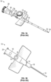
- the prior art catheter assembly 10 may correspond to the BD VENFLON TM Pro Safety Shielded IV Catheter or another catheter assembly.
- the prior art catheter assembly 10 includes a catheter adapter 12 and a catheter 13 extending distally from the catheter adapter 12.
- the catheter adapter 12 includes a body 16, which includes a distal end 18, a proximal end 20, and a lumen 22 extending through the distal end 18 and the proximal end 20.
- the catheter adapter 12 includes a side port 14 extending outwardly from the body 16 and may be covered by a removable cap 15.
- a valve 24 is disposed in the lumen 22 and seals the side port 14 from the lumen 22.
- the prior art catheter assembly 10 may be unable to withstand the pressure that is delivered by a power injection device 26 coupled to the side port 14, which may be used for power injection.
- the minimum pressure required for power injection is 300 psi.
- the valve 24 may be the weakest component of the prior art catheter assembly 10.
- valve 24 may shift in a distal direction or a proximal direction in response to power injection.
- the fluid in response to the power injection device 26 delivering the fluid at a high pressure, such as above 300 psi, the fluid may flow between an inner surface of the catheter adapter 12 and an outer surface of the valve 24 in a manner that shifts the valve 24 from its original position, illustrated in Figure 1C , to a distal position, illustrated in Figure 1D , or a proximal position.
- the valve 24 may be prevented from resealing the side port 14 from the lumen 22 after completion of the power injection and may no longer be functional.
- the prior art catheter assembly 10 may be removably coupled to a prior art needle assembly 28, which may include a needle hub 30 and an introducer needle 32.
- the introducer needle 32 may include a sharp distal tip 34.
- a proximal end of the introducer needle 32 may be secured within the needle hub 30.
- the introducer needle 32 may extend through the catheter 13 when the prior art catheter assembly 10 is in an insertion position ready for insertion into vasculature of a patient, as illustrated, for example, in Figure 1A .
- flashback of blood may flow through the sharp distal tip 34 of the introducer needle 32 and may be visible to a clinician between the introducer needle 32 and the catheter 13 and/or at another location within the prior art catheter assembly 10.
- the prior art needle assembly 28 in response to confirmation via the blood flashback that the catheter 13 is positioned within vasculature of the patient, the prior art needle assembly 28 may be removed from the prior art catheter assembly 10, as illustrated in Figure 1B .
- the introducer needle 32 of the prior art needle assembly 28 may extend through the valve 24 disposed within the lumen 22 of the catheter adapter 12.
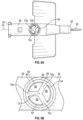
- the catheter assembly 29 may include or correspond to the prior art catheter assembly 10.
- one or more components of the catheter assembly 29 may include or correspond to one or more components of the prior art catheter assembly 10.
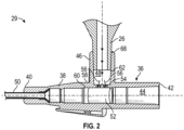
- the catheter assembly 29 may include a catheter adapter 36.
- the catheter adapter 36 may include a body 38, which may include a distal end 40, a proximal end 42, and a first lumen 44 extending through the distal end 40 and the proximal end 42.
- the catheter adapter 36 may include a side port 46 extending outwardly from the body 38.
- the side port 46 may be disposed between the distal end 40 and the proximal end 42.
- the side port 46 may include a second lumen 48, which may be perpendicular to the first lumen 44.
- the second lumen 48 may extend through the side port 46 to the first lumen 44.
- the first lumen 44 may be generally cylindrical, and the second lumen 48 may be generally cylindrical.
- the catheter assembly 29 may include a catheter 50, which may extend distally from the distal end 40 of the body 38 and may be secured within the catheter adapter 36.
- the catheter assembly 29 may include a valve 52 disposed within the first lumen 44.
- the valve 52 may seal the first lumen 44 from the second lumen 48, preventing fluid from travelling between the first lumen 44 and the second lumen 48.
- an outer surface of the valve 52 may be cylindrical.
- the valve 52 may be solid.
- the valve 52 may include an opening extending through a distal end of the valve 52 and a proximal end of the valve 52.
- the valve 52 may be constructed of silicon or another suitable material.
- the catheter assembly 29 may include a divider 54, which may be disposed within the second lumen 48.
- the catheter adapter 36 and the divider 54 may be monolithically formed as a single unit, which may secure the divider 54 in response to power injection through the side port 46.
- the divider 54 may divide the second lumen 48 into multiple openings 56.
- the divider 54 may be constructed of plastic, metal, or another suitable material. In some embodiments, the divider 54 may be rigid.
- the divider 54 may be proximate the first lumen 44. In some embodiments, the divider may be disposed between an outer surface 58 of the body 38 and an inner surface 60 of the body 38 forming the first lumen 44. In some embodiments, the divider 54 may be disposed between the side port 46 and the inner surface 60 of the body 38. In some embodiments, the divider 54 may be disposed within the side port 46 or a portion of the second lumen 48 disposed within the side port 46.
- the divider 54 may contact the valve 52. In some embodiments, the divider 54 may be symmetrical, which may provide an evenly distributed amount of pressure on the valve 52 during power injection. In some embodiments, the divider 54 may be asymmetrical. In some embodiments, one or more of the multiple openings 56 may be identical. In some embodiments, the divider 54 may include various shapes and patterns.
- the divider 54 may facilitate high flow rates and maintenance of a high pressure within the catheter adapter 36 while also maintaining the integrity of the valve 52. In some embodiments, the divider 54 may increase a burst value of the valve 52 such that the valve 52 is able to withstand high pressure during power injection into the catheter adapter 36 without breaking. Thus, in some embodiments, the valve 52 may include a multi-use valve usable for multiple power injections.
- the divider 54 in response to delivering the fluid into the side port 46 at a pressure during power injection, may reduce or eliminate expansion of the valve 52 as the valve 52 contacts and presses upon the divider 54. In some embodiments, in response to delivering the fluid into the side port 46 at the pressure during power injection, the divider 54 may reduce or eliminate shifting of the valve 52 in a proximal direction and a distal direction.
- the pressure may be greater than 348 psi. In some embodiments, the pressure may be between 348 psi and 478 psi. In some embodiments, the pressure may be between 348 psi and 728 psi. In some embodiments, the pressure may be between 300 psi and 800 psi. In some embodiments, the pressure may be between 350 psi and 800 psi. In some embodiments, the pressure may be between 700 psi and 1000 psi.
- the pressure may be between 300 psi and 400 psi, between 400 psi and 500 psi, between 500 psi and 600 psi, between 600 psi and 700 psi, between 700 psi and 800 psi, or between 800 psi and 900 psi.
- the divider 54 in response to delivering the fluid into the side port 46 at the pressure, the divider 54 may inhibit expansion of the valve 52 and/or shifting of the valve 52 in the proximal direction and the distal direction.
- the multiple openings 56 may be configured to allow fluid to flow from the side port 46 to the body 38 at a flow rate of between about 3 mL and 8 mL per second and/or at the pressure. In some embodiments, the multiple openings 56 may be configured to allow fluid to flow from the side port 46 to the body 38 at another suitable flow rate.
- the burst value of the valve 52 may be greater than 348 psi. In some embodiments, the burst value of the valve 52 may be between 348 psi and 478 psi. In some embodiments, the burst value of the valve 52 may be between 348 psi and 728 psi. In some embodiments, the burst value of the valve 52 may be between 300 psi and 800 psi. In some embodiments, the burst value of the valve 52 may be between 350 psi and 800 psi. In some embodiments, the burst value of the valve 52 may be between 700 psi and 1000 psi.
- the burst value of the valve 52 may be between 300 psi and 400 psi, between 400 psi and 500 psi, between 500 psi and 600 psi, between 600 psi and 700 psi, between 700 psi and 800 psi, or between 800 psi and 900 psi.
- the valve 52 may be stronger than body 38, which may rupture or break at a lower pressure than the valve 52.
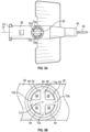
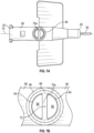
- the catheter adapter 36 may include another inner surface 62, which may form the second lumen 48.
- outer edges 64 of the multiple openings 56 may form or be aligned with a shape 66 which may be an ellipse or a geometric shape, such as a circle or triangle.
- the shape 66 may be symmetric.
- the outer edges 64 may include arcs, which may connect two lines forming inner edges of the multiple openings 56 or ends of a single line forming an inner edge of the multiple openings 56. In some embodiments, the two lines may intersect at a corner or a rounded edge.
- a diameter of the shape 66 which may include a maximum diameter of the shape 66, may be less than a diameter of a portion of the other inner surface 62 that is proximate the shape 66 and closer to an outer opening 68 of the side port 46, as illustrated, for example, in Figures 3-4 .
- the second lumen 48 may be stepped and the divider 54 may extend from a stepped surface.
- the diameter of the shape 66 may be equal to the diameter of the portion of the other inner surface 62 that is proximate the shape 66 and closer to an outer opening 68 of the side port 46.
- the divider 54 may not extend from a stepped surface.
- the divider 54 may include multiple arms 70, which may extend from the shape 66 to a central axis 72 (see also Figure 2 ) of the second lumen 48.
- the divider 54 may include X-shape.
- the multiple arms 70 may include a first arm 70a, a second arm 70b, a third arm 70c, and a fourth arm 70d.
- two of the first arm 70a, the second arm 70b, the third arm 70c, and the fourth arm 70d may be parallel to a longitudinal axis 74 (see also Figure 2 ) of the catheter adapter 36, as illustrated in Figures 3A-3B .
- the first arm 70a, the second arm 70b, the third arm 70c, and the fourth arm 70d may be offset from the longitudinal axis 74 of the catheter adapter 36, such as, for example, by about 45° or another suitable angle.
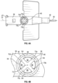
- the divider 54 may include a Y-shape.
- the multiple arms 70 may include the first arm 70a, the second arm 70b, and the third arm 70c.
- one of the first arm 70a, the second arm 70b, and the third arm 70c may be parallel to the longitudinal axis 74 of the catheter adapter 36 and may point distally, as illustrated in Figures 5A-5B .
- one of the first arm 70a, the second arm 70b, and the third arm 70c may be parallel to the longitudinal axis 74 of the catheter adapter 36 and may point proximally.
- none of the first arm 70a, the second arm 70b, or the third arm 70c may be aligned with the longitudinal axis 74 of the catheter adapter 36.
- the divider 54 may be linear and may extend from one side of the shape 66 to another side of the shape 66. In some embodiments, the divider 54 that is linear and/or oriented perpendicular to the longitudinal axis 74 of the catheter adapter 36 may reduce leakage of fluid between the outer surface of the valve 52 and the inner surface 60 of the body 38 that might otherwise shift the valve 52 in the proximal direction or the distal direction during power injection. In some embodiments, the divider 54 may be perpendicular to the longitudinal axis 74 of the catheter adapter 36, as illustrated in Figures 7A-7B . In some embodiments, the divider 54 may be parallel to the longitudinal axis 74 of the catheter adapter 36, as illustrated in Figures 8A-8B .
- a method of delivering fluid into the catheter adapter 36 may include coupling the power injection device 26 to the side port 14 of the catheter adapter 12. In some embodiments, the method may include delivering fluid, via the power injection device 26, into the side port 14 at the pressure. In some embodiments, an integrity of the valve 52 may be maintained in response to delivering the fluid into the side port 14 at the pressure. In some embodiments, the pressure may not exceed the burst value of the valve 52.
Landscapes
- Health & Medical Sciences (AREA)
- Heart & Thoracic Surgery (AREA)
- Life Sciences & Earth Sciences (AREA)
- Hematology (AREA)
- Public Health (AREA)
- Anesthesiology (AREA)
- Biomedical Technology (AREA)
- Engineering & Computer Science (AREA)
- Veterinary Medicine (AREA)
- Animal Behavior & Ethology (AREA)
- General Health & Medical Sciences (AREA)
- Pulmonology (AREA)
- Biophysics (AREA)
- Epidemiology (AREA)
- Urology & Nephrology (AREA)
- Vascular Medicine (AREA)
- Infusion, Injection, And Reservoir Apparatuses (AREA)
- Media Introduction/Drainage Providing Device (AREA)
Claims (15)
- Katheteranordnung (29) mit:einem Katheteradapter (36) mit:einem Körper (38) mit einem distalen Ende (40), einem proximalen Ende (42), und einem ersten Lumen (44), das sich durch das distale Ende und das proximale Ende erstreckt;einem Seitenport (46), der sich von dem Körper nach außen erstreckt und zwischen dem distalen Ende und dem proximalen Ende angeordnet ist, und wobei der Seitenport ein zweites Lumen (48) senkrecht zu dem ersten Lumen aufweist;einem Katheter (50), der sich distal von dem distalen Ende des Körpers erstreckt;einem Ventil (52), das in dem ersten Lumen angeordnet ist und das erste Lumen gegen das zweite Lumen abdichtet, wobei eine Außenseite des Ventils zylindrisch ist; undeinem Teiler (54), der in dem zweiten Lumen angeordnet ist, wobei der Teiler das zweite Lumen in mehrere Öffnungen (56) teilt.
- Katheteranordnung nach Anspruch 1, bei welcher der Teiler nahe dem ersten Lumen vorgesehen ist.
- Katheteranordnung nach Anspruch 1, bei welcher der Teiler das Ventil berührt.
- Katheteranordnung nach Anspruch 1, bei welcher der Teiler symmetrisch ist.
- Katheteranordnung nach Anspruch 4, bei welcher jede der mehreren Öffnungen identisch ist.
- Katheteranordnung nach Anspruch 1, bei welcher Außenränder (64) der mehreren Öffnungen eine symmetrische Form aufweisen, wobei der Teiler linear ist und sich von einer Seite der symmetrischen Form zu einer anderen Seite der symmetrischen Form erstreckt.
- Katheteranordnung nach Anspruch 6, bei welcher der Teiler senkrecht oder parallel zu einer Längsachse (74) der Katheteradapters verläuft.
- Katheteranordnung nach Anspruch 1, bei welcher die Außenränder der mehreren Öffnungen eine symmetrische Form bilden, wobei der Teiler mehrere Arme (70) aufweist, die sich von der symmetrischen Form zu einer Mittelachse (72) des zweiten Lumens erstrecken.
- Katheteranordnung nach Anspruch 8, bei welcher der Teiler eine V-Form aufweist.
- Katheteranordnung nach Anspruch 9, bei welcher die mehreren Arme einen ersten Arm (70a), einen zweiten Arm (70b), einen dritten Arm (70c) und einen vierten Arm (70d) aufweisen, wobei zwei Arme unter dem ersten Arm, dem zweiten Arm, dem dritten Arm und dem vierten Arm parallel zu einer Längsachse des Katheteradapters verlaufen.
- Katheteranordnung nach Anspruch 9, bei welcher die X-Form einen ersten Arm, einen zweiten Arm, einen dritten Arm und einen vierten Arm aufweisen, wobei der erste Arm, der zweite Arm, der dritte Arm und der vierte Arm gegenüber einer Längsachse des Katheteradapters sind.
- Katheteranordnung nach Anspruch 9, bei welcher der Teiler eine Y-Form aufweist.
- Katheteranordnung nach Anspruch 12, bei welcher die mehreren Arme einen ersten Arm, einen zweiten Arm und einen dritten Arm aufweisen, wobei ein Arm unter dem ersten Arm, dem zweiten Arm und dem dritten Arm parallel zu einer Längsachse des Katheteradapters verläuft und distal gerichtet ist.
- Katheteranordnung nach Anspruch 12, bei welcher die mehreren Arme einen ersten Arm, einen zweiten Arm und einen dritten Arm aufweisen, wobei ein Arm unter dem ersten Arm, dem zweiten Arm und dem dritten Arm parallel zu einer Längsachse des Katheteradapters verläuft und proximal gerichtet ist.
- Katheteranordnung nach Anspruch 1, bei welcher der Katheteradapter und der Teiler monolithisch als eine Einheit ausgebildet sind.
Priority Applications (1)
| Application Number | Priority Date | Filing Date | Title |
|---|---|---|---|
| EP24194714.2A EP4438101A3 (de) | 2019-05-29 | 2020-05-21 | Katheteranordnung mit injektionsport |
Applications Claiming Priority (3)
| Application Number | Priority Date | Filing Date | Title |
|---|---|---|---|
| US201962854123P | 2019-05-29 | 2019-05-29 | |
| US16/878,359 US11324927B2 (en) | 2019-05-29 | 2020-05-19 | Catheter assembly having an injection port and related methods |
| PCT/US2020/033971 WO2020242878A1 (en) | 2019-05-29 | 2020-05-21 | Catheter assembly having an injection port and related methods |
Related Child Applications (1)
| Application Number | Title | Priority Date | Filing Date |
|---|---|---|---|
| EP24194714.2A Division EP4438101A3 (de) | 2019-05-29 | 2020-05-21 | Katheteranordnung mit injektionsport |
Publications (3)
| Publication Number | Publication Date |
|---|---|
| EP3976153A1 EP3976153A1 (de) | 2022-04-06 |
| EP3976153C0 EP3976153C0 (de) | 2024-09-11 |
| EP3976153B1 true EP3976153B1 (de) | 2024-09-11 |
Family
ID=73506322
Family Applications (2)
| Application Number | Title | Priority Date | Filing Date |
|---|---|---|---|
| EP20731745.4A Active EP3976153B1 (de) | 2019-05-29 | 2020-05-21 | Katheteranordnung mit injektionsöffnung |
| EP24194714.2A Pending EP4438101A3 (de) | 2019-05-29 | 2020-05-21 | Katheteranordnung mit injektionsport |
Family Applications After (1)
| Application Number | Title | Priority Date | Filing Date |
|---|---|---|---|
| EP24194714.2A Pending EP4438101A3 (de) | 2019-05-29 | 2020-05-21 | Katheteranordnung mit injektionsport |
Country Status (11)
| Country | Link |
|---|---|
| US (2) | US11324927B2 (de) |
| EP (2) | EP3976153B1 (de) |
| JP (1) | JP7515522B2 (de) |
| KR (1) | KR102814364B1 (de) |
| CN (3) | CN112007232B (de) |
| AU (1) | AU2020284295B2 (de) |
| BR (1) | BR112021023369A2 (de) |
| CA (1) | CA3138305A1 (de) |
| MX (1) | MX2021014055A (de) |
| SG (1) | SG11202112777SA (de) |
| WO (1) | WO2020242878A1 (de) |
Families Citing this family (7)
| Publication number | Priority date | Publication date | Assignee | Title |
|---|---|---|---|---|
| WO2019065943A1 (ja) | 2017-09-29 | 2019-04-04 | テルモ株式会社 | カテーテル組立体及び医療用弁 |
| US11324927B2 (en) * | 2019-05-29 | 2022-05-10 | Becton, Dickinson And Company | Catheter assembly having an injection port and related methods |
| MX2023002964A (es) * | 2020-09-15 | 2023-04-05 | Becton Dickinson Co | Conjunto de cateter con cambio de angulo y metodos relacionados. |
| US11992647B2 (en) | 2021-01-20 | 2024-05-28 | Becton, Dickinson And Company | Valve retainer ring and related systems and methods |
| JP2024516999A (ja) * | 2021-05-10 | 2024-04-18 | ベクトン・ディキンソン・アンド・カンパニー | カテーテル組立体内の環状弁の固定 |
| JP2024518176A (ja) * | 2021-05-14 | 2024-04-25 | ベクトン・ディキンソン・アンド・カンパニー | サイドポート経路を有するカテーテルアセンブリおよび関連する方法 |
| USD1077993S1 (en) * | 2021-08-27 | 2025-06-03 | Botrista, Inc. | Dual-mode fluid connector |
Family Cites Families (13)
| Publication number | Priority date | Publication date | Assignee | Title |
|---|---|---|---|---|
| US5098405A (en) * | 1991-01-31 | 1992-03-24 | Becton, Dickinson And Company | Apparatus and method for a side port cathether adapter with a one piece integral combination valve |
| WO2009044151A1 (en) | 2007-10-03 | 2009-04-09 | Neorad As | Monitoring the injection of fluid |
| US8496629B2 (en) | 2008-04-22 | 2013-07-30 | Becton, Dickinson And Company | Catheter hole having a flow breaking feature |
| US9126012B2 (en) | 2011-10-06 | 2015-09-08 | Becton, Dickinson And Company | Intravenous catheter with duckbill valve |
| US9737686B2 (en) * | 2012-03-12 | 2017-08-22 | Becton, Dickinson And Company | Catheter adapter port valve |
| US9895525B2 (en) * | 2014-01-21 | 2018-02-20 | Becton, Dickinson And Company | Ported catheter adapter with integrated septum actuator retention |
| US9750925B2 (en) | 2014-01-21 | 2017-09-05 | Becton, Dickinson And Company | Ported catheter adapter having combined port and blood control valve with venting |
| WO2016036468A1 (en) | 2014-09-01 | 2016-03-10 | AUST Development, LLC | Catheter hubs and valves for minimizing embolic potential |
| SG10201908316RA (en) | 2015-03-10 | 2019-10-30 | Braun Melsungen Ag | Catheter assemblies with flow control valve mechanisms and related methods |
| EP3180068B1 (de) * | 2015-07-01 | 2018-11-07 | Poly Medicure Limited | Intravenöse kathetervorrichtung mit integriertem dreiwege-absperrhahn |
| AU2016344428B2 (en) * | 2015-10-28 | 2021-09-30 | Carefusion 303, Inc. | Closed IV access device with y-port needle-free connector |
| US10543354B2 (en) * | 2017-09-27 | 2020-01-28 | Becton, Dickinson And Company | Peripheral intravenous catheters having flow diverting features |
| US11324927B2 (en) * | 2019-05-29 | 2022-05-10 | Becton, Dickinson And Company | Catheter assembly having an injection port and related methods |
-
2020
- 2020-05-19 US US16/878,359 patent/US11324927B2/en active Active
- 2020-05-21 SG SG11202112777SA patent/SG11202112777SA/en unknown
- 2020-05-21 JP JP2021570828A patent/JP7515522B2/ja active Active
- 2020-05-21 EP EP20731745.4A patent/EP3976153B1/de active Active
- 2020-05-21 EP EP24194714.2A patent/EP4438101A3/de active Pending
- 2020-05-21 MX MX2021014055A patent/MX2021014055A/es unknown
- 2020-05-21 KR KR1020217041802A patent/KR102814364B1/ko active Active
- 2020-05-21 AU AU2020284295A patent/AU2020284295B2/en active Active
- 2020-05-21 BR BR112021023369A patent/BR112021023369A2/pt unknown
- 2020-05-21 CA CA3138305A patent/CA3138305A1/en active Pending
- 2020-05-21 WO PCT/US2020/033971 patent/WO2020242878A1/en not_active Ceased
- 2020-05-29 CN CN202010472848.XA patent/CN112007232B/zh active Active
- 2020-05-29 CN CN202020958229.7U patent/CN213251945U/zh not_active Withdrawn - After Issue
- 2020-05-29 CN CN202511039773.5A patent/CN120695294A/zh active Pending
-
2022
- 2022-04-12 US US17/718,567 patent/US11904116B2/en active Active
Also Published As
| Publication number | Publication date |
|---|---|
| US11904116B2 (en) | 2024-02-20 |
| EP3976153A1 (de) | 2022-04-06 |
| BR112021023369A2 (pt) | 2022-01-04 |
| JP7515522B2 (ja) | 2024-07-12 |
| EP3976153C0 (de) | 2024-09-11 |
| WO2020242878A1 (en) | 2020-12-03 |
| KR20220016118A (ko) | 2022-02-08 |
| KR102814364B1 (ko) | 2025-05-30 |
| EP4438101A2 (de) | 2024-10-02 |
| US20200376234A1 (en) | 2020-12-03 |
| CN120695294A (zh) | 2025-09-26 |
| CN213251945U (zh) | 2021-05-25 |
| MX2021014055A (es) | 2021-12-10 |
| US11324927B2 (en) | 2022-05-10 |
| AU2020284295A1 (en) | 2022-01-06 |
| JP2022534976A (ja) | 2022-08-04 |
| CN112007232B (zh) | 2025-08-15 |
| AU2020284295B2 (en) | 2025-05-22 |
| US20220233822A1 (en) | 2022-07-28 |
| CN112007232A (zh) | 2020-12-01 |
| CA3138305A1 (en) | 2020-12-03 |
| SG11202112777SA (en) | 2021-12-30 |
| EP4438101A3 (de) | 2024-12-25 |
Similar Documents
| Publication | Publication Date | Title |
|---|---|---|
| EP3976153B1 (de) | Katheteranordnung mit injektionsöffnung | |
| US12097344B2 (en) | Introducer needle having a bump and related systems and methods | |
| US20120232498A1 (en) | Systems and methods to compensate for compression forces in an intravascular device | |
| EP3833421B1 (de) | Blutkontrollseptum und zugehörige systeme | |
| US20220355081A1 (en) | Catheter assembly having a side port valve | |
| US20200384185A1 (en) | Catheter assembly flushing device and related methods | |
| US11992647B2 (en) | Valve retainer ring and related systems and methods | |
| US20220379103A1 (en) | Retainer element to secure a catheter adapter valve | |
| EP4281157A1 (de) | Ventilhalterring sowie zugehörige systeme und verfahren | |
| US20250135177A1 (en) | Slip luer retainer |
Legal Events
| Date | Code | Title | Description |
|---|---|---|---|
| STAA | Information on the status of an ep patent application or granted ep patent |
Free format text: STATUS: UNKNOWN |
|
| STAA | Information on the status of an ep patent application or granted ep patent |
Free format text: STATUS: THE INTERNATIONAL PUBLICATION HAS BEEN MADE |
|
| PUAI | Public reference made under article 153(3) epc to a published international application that has entered the european phase |
Free format text: ORIGINAL CODE: 0009012 |
|
| STAA | Information on the status of an ep patent application or granted ep patent |
Free format text: STATUS: REQUEST FOR EXAMINATION WAS MADE |
|
| 17P | Request for examination filed |
Effective date: 20211207 |
|
| AK | Designated contracting states |
Kind code of ref document: A1 Designated state(s): AL AT BE BG CH CY CZ DE DK EE ES FI FR GB GR HR HU IE IS IT LI LT LU LV MC MK MT NL NO PL PT RO RS SE SI SK SM TR |
|
| DAV | Request for validation of the european patent (deleted) | ||
| DAX | Request for extension of the european patent (deleted) | ||
| GRAP | Despatch of communication of intention to grant a patent |
Free format text: ORIGINAL CODE: EPIDOSNIGR1 |
|
| STAA | Information on the status of an ep patent application or granted ep patent |
Free format text: STATUS: GRANT OF PATENT IS INTENDED |
|
| RIC1 | Information provided on ipc code assigned before grant |
Ipc: A61M 25/06 20060101ALN20240320BHEP Ipc: A61M 39/06 20060101ALI20240320BHEP Ipc: A61M 39/04 20060101ALI20240320BHEP Ipc: A61M 25/00 20060101AFI20240320BHEP |
|
| INTG | Intention to grant announced |
Effective date: 20240417 |
|
| GRAS | Grant fee paid |
Free format text: ORIGINAL CODE: EPIDOSNIGR3 |
|
| GRAA | (expected) grant |
Free format text: ORIGINAL CODE: 0009210 |
|
| STAA | Information on the status of an ep patent application or granted ep patent |
Free format text: STATUS: THE PATENT HAS BEEN GRANTED |
|
| AK | Designated contracting states |
Kind code of ref document: B1 Designated state(s): AL AT BE BG CH CY CZ DE DK EE ES FI FR GB GR HR HU IE IS IT LI LT LU LV MC MK MT NL NO PL PT RO RS SE SI SK SM TR |
|
| REG | Reference to a national code |
Ref country code: GB Ref legal event code: FG4D |
|
| REG | Reference to a national code |
Ref country code: CH Ref legal event code: EP |
|
| REG | Reference to a national code |
Ref country code: DE Ref legal event code: R096 Ref document number: 602020037532 Country of ref document: DE |
|
| REG | Reference to a national code |
Ref country code: IE Ref legal event code: FG4D |
|
| U01 | Request for unitary effect filed |
Effective date: 20241011 |
|
| U07 | Unitary effect registered |
Designated state(s): AT BE BG DE DK EE FI FR IT LT LU LV MT NL PT RO SE SI Effective date: 20241029 |
|
| PG25 | Lapsed in a contracting state [announced via postgrant information from national office to epo] |
Ref country code: NO Free format text: LAPSE BECAUSE OF FAILURE TO SUBMIT A TRANSLATION OF THE DESCRIPTION OR TO PAY THE FEE WITHIN THE PRESCRIBED TIME-LIMIT Effective date: 20241211 |
|
| PG25 | Lapsed in a contracting state [announced via postgrant information from national office to epo] |
Ref country code: GR Free format text: LAPSE BECAUSE OF FAILURE TO SUBMIT A TRANSLATION OF THE DESCRIPTION OR TO PAY THE FEE WITHIN THE PRESCRIBED TIME-LIMIT Effective date: 20241212 |
|
| PG25 | Lapsed in a contracting state [announced via postgrant information from national office to epo] |
Ref country code: HR Free format text: LAPSE BECAUSE OF FAILURE TO SUBMIT A TRANSLATION OF THE DESCRIPTION OR TO PAY THE FEE WITHIN THE PRESCRIBED TIME-LIMIT Effective date: 20240911 |
|
| PG25 | Lapsed in a contracting state [announced via postgrant information from national office to epo] |
Ref country code: RS Free format text: LAPSE BECAUSE OF FAILURE TO SUBMIT A TRANSLATION OF THE DESCRIPTION OR TO PAY THE FEE WITHIN THE PRESCRIBED TIME-LIMIT Effective date: 20241211 Ref country code: ES Free format text: LAPSE BECAUSE OF FAILURE TO SUBMIT A TRANSLATION OF THE DESCRIPTION OR TO PAY THE FEE WITHIN THE PRESCRIBED TIME-LIMIT Effective date: 20240911 |
|
| PG25 | Lapsed in a contracting state [announced via postgrant information from national office to epo] |
Ref country code: RS Free format text: LAPSE BECAUSE OF FAILURE TO SUBMIT A TRANSLATION OF THE DESCRIPTION OR TO PAY THE FEE WITHIN THE PRESCRIBED TIME-LIMIT Effective date: 20241211 Ref country code: NO Free format text: LAPSE BECAUSE OF FAILURE TO SUBMIT A TRANSLATION OF THE DESCRIPTION OR TO PAY THE FEE WITHIN THE PRESCRIBED TIME-LIMIT Effective date: 20241211 Ref country code: HR Free format text: LAPSE BECAUSE OF FAILURE TO SUBMIT A TRANSLATION OF THE DESCRIPTION OR TO PAY THE FEE WITHIN THE PRESCRIBED TIME-LIMIT Effective date: 20240911 Ref country code: GR Free format text: LAPSE BECAUSE OF FAILURE TO SUBMIT A TRANSLATION OF THE DESCRIPTION OR TO PAY THE FEE WITHIN THE PRESCRIBED TIME-LIMIT Effective date: 20241212 Ref country code: ES Free format text: LAPSE BECAUSE OF FAILURE TO SUBMIT A TRANSLATION OF THE DESCRIPTION OR TO PAY THE FEE WITHIN THE PRESCRIBED TIME-LIMIT Effective date: 20240911 |
|
| PG25 | Lapsed in a contracting state [announced via postgrant information from national office to epo] |
Ref country code: IS Free format text: LAPSE BECAUSE OF FAILURE TO SUBMIT A TRANSLATION OF THE DESCRIPTION OR TO PAY THE FEE WITHIN THE PRESCRIBED TIME-LIMIT Effective date: 20250111 |
|
| PG25 | Lapsed in a contracting state [announced via postgrant information from national office to epo] |
Ref country code: SM Free format text: LAPSE BECAUSE OF FAILURE TO SUBMIT A TRANSLATION OF THE DESCRIPTION OR TO PAY THE FEE WITHIN THE PRESCRIBED TIME-LIMIT Effective date: 20240911 |
|
| PG25 | Lapsed in a contracting state [announced via postgrant information from national office to epo] |
Ref country code: CZ Free format text: LAPSE BECAUSE OF FAILURE TO SUBMIT A TRANSLATION OF THE DESCRIPTION OR TO PAY THE FEE WITHIN THE PRESCRIBED TIME-LIMIT Effective date: 20240911 Ref country code: PL Free format text: LAPSE BECAUSE OF FAILURE TO SUBMIT A TRANSLATION OF THE DESCRIPTION OR TO PAY THE FEE WITHIN THE PRESCRIBED TIME-LIMIT Effective date: 20240911 |
|
| PG25 | Lapsed in a contracting state [announced via postgrant information from national office to epo] |
Ref country code: SK Free format text: LAPSE BECAUSE OF FAILURE TO SUBMIT A TRANSLATION OF THE DESCRIPTION OR TO PAY THE FEE WITHIN THE PRESCRIBED TIME-LIMIT Effective date: 20240911 |
|
| U20 | Renewal fee for the european patent with unitary effect paid |
Year of fee payment: 6 Effective date: 20250423 |
|
| PGFP | Annual fee paid to national office [announced via postgrant information from national office to epo] |
Ref country code: GB Payment date: 20250423 Year of fee payment: 6 |
|
| PLBE | No opposition filed within time limit |
Free format text: ORIGINAL CODE: 0009261 |
|
| STAA | Information on the status of an ep patent application or granted ep patent |
Free format text: STATUS: NO OPPOSITION FILED WITHIN TIME LIMIT |
|
| 26N | No opposition filed |
Effective date: 20250612 |