EP3975370A1 - Improvements in or relating to power transmission networks - Google Patents
Improvements in or relating to power transmission networks Download PDFInfo
- Publication number
- EP3975370A1 EP3975370A1 EP20275149.1A EP20275149A EP3975370A1 EP 3975370 A1 EP3975370 A1 EP 3975370A1 EP 20275149 A EP20275149 A EP 20275149A EP 3975370 A1 EP3975370 A1 EP 3975370A1
- Authority
- EP
- European Patent Office
- Prior art keywords
- voltage
- network
- converter
- power
- virtual
- Prior art date
- Legal status (The legal status is an assumption and is not a legal conclusion. Google has not performed a legal analysis and makes no representation as to the accuracy of the status listed.)
- Granted
Links
Images


Classifications
-
- H—ELECTRICITY
- H02—GENERATION; CONVERSION OR DISTRIBUTION OF ELECTRIC POWER
- H02J—ELECTRIC POWER NETWORKS; CIRCUIT ARRANGEMENTS OR SYSTEMS FOR SUPPLYING OR DISTRIBUTING ELECTRIC POWER; SYSTEMS FOR STORING ELECTRIC ENERGY
- H02J3/00—Circuit arrangements for AC mains or AC distribution networks
- H02J3/36—Arrangements for transfer of electric power between AC networks via high-voltage DC [HVDC] links; Arrangements for transfer of electric power between generators and networks via HVDC links
-
- H—ELECTRICITY
- H02—GENERATION; CONVERSION OR DISTRIBUTION OF ELECTRIC POWER
- H02J—ELECTRIC POWER NETWORKS; CIRCUIT ARRANGEMENTS OR SYSTEMS FOR SUPPLYING OR DISTRIBUTING ELECTRIC POWER; SYSTEMS FOR STORING ELECTRIC ENERGY
- H02J3/00—Circuit arrangements for AC mains or AC distribution networks
- H02J3/001—Arrangements for handling faults or abnormalities, e.g. emergencies or contingencies
- H02J3/0014—Arrangements for handling faults or abnormalities, e.g. emergencies or contingencies for preventing or reducing power oscillations in networks
-
- H—ELECTRICITY
- H02—GENERATION; CONVERSION OR DISTRIBUTION OF ELECTRIC POWER
- H02M—APPARATUS FOR CONVERSION BETWEEN AC AND AC, BETWEEN AC AND DC, OR BETWEEN DC AND DC, AND FOR USE WITH MAINS OR SIMILAR POWER SUPPLY SYSTEMS; CONVERSION OF DC OR AC INPUT POWER INTO SURGE OUTPUT POWER; CONTROL OR REGULATION THEREOF
- H02M7/00—Conversion of AC power input into DC power output; Conversion of DC power input into AC power output
- H02M7/42—Conversion of DC power input into AC power output without possibility of reversal
- H02M7/44—Conversion of DC power input into AC power output without possibility of reversal by static converters
- H02M7/48—Conversion of DC power input into AC power output without possibility of reversal by static converters using discharge tubes with control electrode or semiconductor devices with control electrode
- H02M7/483—Converters with outputs that each can have more than two voltages levels
- H02M7/4835—Converters with outputs that each can have more than two voltages levels comprising two or more cells, each including a switchable capacitor, the capacitors having a nominal charge voltage which corresponds to a given fraction of the input voltage, and the capacitors being selectively connected in series to determine the instantaneous output voltage
-
- H—ELECTRICITY
- H02—GENERATION; CONVERSION OR DISTRIBUTION OF ELECTRIC POWER
- H02M—APPARATUS FOR CONVERSION BETWEEN AC AND AC, BETWEEN AC AND DC, OR BETWEEN DC AND DC, AND FOR USE WITH MAINS OR SIMILAR POWER SUPPLY SYSTEMS; CONVERSION OF DC OR AC INPUT POWER INTO SURGE OUTPUT POWER; CONTROL OR REGULATION THEREOF
- H02M7/00—Conversion of AC power input into DC power output; Conversion of DC power input into AC power output
- H02M7/66—Conversion of AC power input into DC power output; Conversion of DC power input into AC power output with possibility of reversal
- H02M7/68—Conversion of AC power input into DC power output; Conversion of DC power input into AC power output with possibility of reversal by static converters
- H02M7/72—Conversion of AC power input into DC power output; Conversion of DC power input into AC power output with possibility of reversal by static converters using discharge tubes with control electrode or semiconductor devices with control electrode
-
- H—ELECTRICITY
- H02—GENERATION; CONVERSION OR DISTRIBUTION OF ELECTRIC POWER
- H02J—ELECTRIC POWER NETWORKS; CIRCUIT ARRANGEMENTS OR SYSTEMS FOR SUPPLYING OR DISTRIBUTING ELECTRIC POWER; SYSTEMS FOR STORING ELECTRIC ENERGY
- H02J3/00—Circuit arrangements for AC mains or AC distribution networks
- H02J3/36—Arrangements for transfer of electric power between AC networks via high-voltage DC [HVDC] links; Arrangements for transfer of electric power between generators and networks via HVDC links
- H02J2003/365—Reducing harmonics or oscillations in HVDC
-
- H—ELECTRICITY
- H02—GENERATION; CONVERSION OR DISTRIBUTION OF ELECTRIC POWER
- H02J—ELECTRIC POWER NETWORKS; CIRCUIT ARRANGEMENTS OR SYSTEMS FOR SUPPLYING OR DISTRIBUTING ELECTRIC POWER; SYSTEMS FOR STORING ELECTRIC ENERGY
- H02J2101/00—Supply or distribution of decentralised, dispersed or local electric power generation
- H02J2101/20—Dispersed power generation using renewable energy sources
- H02J2101/28—Wind energy
-
- H—ELECTRICITY
- H02—GENERATION; CONVERSION OR DISTRIBUTION OF ELECTRIC POWER
- H02J—ELECTRIC POWER NETWORKS; CIRCUIT ARRANGEMENTS OR SYSTEMS FOR SUPPLYING OR DISTRIBUTING ELECTRIC POWER; SYSTEMS FOR STORING ELECTRIC ENERGY
- H02J3/00—Circuit arrangements for AC mains or AC distribution networks
- H02J3/38—Arrangements for feeding a single network from two or more generators or sources in parallel; Arrangements for feeding already energised networks from additional generators or sources in parallel
- H02J3/381—Dispersed generators
-
- H—ELECTRICITY
- H02—GENERATION; CONVERSION OR DISTRIBUTION OF ELECTRIC POWER
- H02M—APPARATUS FOR CONVERSION BETWEEN AC AND AC, BETWEEN AC AND DC, OR BETWEEN DC AND DC, AND FOR USE WITH MAINS OR SIMILAR POWER SUPPLY SYSTEMS; CONVERSION OF DC OR AC INPUT POWER INTO SURGE OUTPUT POWER; CONTROL OR REGULATION THEREOF
- H02M1/00—Details of apparatus for conversion
- H02M1/0003—Details of control, feedback or regulation circuits
- H02M1/0025—Arrangements for modifying reference values, feedback values or error values in the control loop of a converter
-
- Y—GENERAL TAGGING OF NEW TECHNOLOGICAL DEVELOPMENTS; GENERAL TAGGING OF CROSS-SECTIONAL TECHNOLOGIES SPANNING OVER SEVERAL SECTIONS OF THE IPC; TECHNICAL SUBJECTS COVERED BY FORMER USPC CROSS-REFERENCE ART COLLECTIONS [XRACs] AND DIGESTS
- Y02—TECHNOLOGIES OR APPLICATIONS FOR MITIGATION OR ADAPTATION AGAINST CLIMATE CHANGE
- Y02E—REDUCTION OF GREENHOUSE GAS [GHG] EMISSIONS, RELATED TO ENERGY GENERATION, TRANSMISSION OR DISTRIBUTION
- Y02E60/00—Enabling technologies; Technologies with a potential or indirect contribution to GHG emissions mitigation
- Y02E60/60—Arrangements for transfer of electric power between AC networks or generators via a high voltage DC link [HVCD]
Definitions
- This invention relates to a power transmission network and to a method of controlling such a network.
- HVDC high voltage direct current
- DC power is typically converted to DC power for transmission via overhead lines, under-sea cables and/or underground cables. This conversion removes the need to compensate for the AC capacitive load effects imposed by the power transmission conduit, i.e. the transmission line or cable, and reduces the cost per kilometre of the lines and/or cables, and thus becomes cost-effective when power needs to be transmitted over a long distance.
- DC power can also be transmitted directly from offshore wind parks to onshore AC power transmission networks.
- converters i.e. power converters
- a power transmission network comprising a power converter having first and second DC converter terminals for connection in use to a DC network and an AC converter terminal electrically connected to a plurality of AC transmission conduits each of which is for connection in use to a respective AC network element configured to operate at a respective individual AC network voltage
- the power converter including a primary converter controller programmed in use to control the transfer of power through the power converter and thereby between the DC network and the plurality of AC network elements, and the primary converter controller being further programmed in use to control each individual AC network voltage by establishing a virtual voltage representative of the plurality of AC network voltages and altering a single AC converter voltage produced by the power converter at the AC converter terminal to adjust the virtual voltage and thereby adjust each individual AC network voltage.
- Such an arrangement is advantageous because it allows a single power converter, i.e. a single power converter with only a single AC output which is therefore able to produce only a single AC converter voltage, to nevertheless control the individual AC network voltages carried by multiple AC transmission conduits to multiple AC network elements, such as respective wind parks.
- the primary converter controller is programmed to establish a virtual voltage commensurate with the average of the individual AC network voltages.
- Establishing such a virtual voltage helps to ensure that each individual AC network voltage in taken into account in a manner that can be readily measured, while nevertheless ensuring that the impact of any alteration in the AC converter voltage is captured in respect of each such AC network voltage.
- the primary converter controller may be programmed to establish the virtual voltage in a vector form having real and imaginary parts.
- a primary converter controller which is programmed to establish the virtual voltage in a vector form having real and imaginary parts, allows the resulting virtual voltage vector to be observed from the perspective of a rotating dq-frame that tracks movement of the vector in a manner that characterises each of the alternating AC network voltages as a DC-like property. This, in turn, allows the resulting virtual vector to be controlled in a similar manner to the voltage and current of a DC system, and so facilitates the desired adjustment of each individual AC network voltage by altering the single AC converter voltage produced by the power converter at the AC converter terminal.
- the primary converter controller is additionally programmed to compare the established virtual voltage with a predetermined virtual voltage reference and to alter the AC converter voltage produced by the power converter to reduce any difference between the established virtual voltage and the predetermined virtual voltage reference.
- the primary converter controller when altering the AC converter voltage produced by the power converter to reduce any difference between the established virtual voltage and the predetermined virtual voltage reference, the primary converter controller takes into account:
- Such programming of the primary converter controller helps to ensure that altering the AC converter voltage the power converter produces adjusts the individual AC network voltages in the desired manner.
- the virtual voltage difference is commensurate with the average voltage difference across the conduit reactances of the AC transmission conduits.
- Configuring the virtual voltage difference in the foregoing manner accurately takes into account the actual voltage differences across the conduit reactances of each individual AC transmission conduit.
- the primary converter controller may be programmed to take into account cross-coupling between the real and imaginary parts of the voltage difference and the virtual voltage difference.
- the power converter further includes a secondary converter controller programmed in use to establish the predetermined virtual voltage reference against which the primary converter controller compares the established virtual voltage.
- a secondary converter controller programmed in the aforementioned manner, allows the power converter to exhibit an increased degree of control over the individual AC network voltages.
- the second converter controller establishes the virtual voltage reference in a manner aimed at maintaining all of the individual AC network voltages within a desired voltage range.
- Such a secondary converter controller allows the power converter to deal with unwanted deviations of one or more of the AC network voltages.
- the secondary converter controller Preferably the secondary converter controller:
- Configuring, i.e. programming, the secondary converter controller in the foregoing manner permits the power converter to maintain the AC network voltages within predetermined voltage minimum and voltage maximum, solely by adjusting the AC converter voltage it produces.
- the secondary converter controller receives in use a virtual voltage command from a higher-level controller and modifies the virtual voltage reference it establishes by determining an adjustment factor and applying the adjustment factor to the received virtual voltage command.
- Such an arrangement allows overall setting of the AC network voltages to be done remotely from the power converter, while still allowing the power converter to exercise finite adjustment of those voltages.
- the secondary converter controller is programmed to modify the virtual voltage reference in a manner that equalises the amount the or each said AC network voltage deviates from the corresponding voltage minimum and voltage maximum.
- a benefit of equalising the amount to which respective AC network voltages deviate from the predetermined voltage minimum and voltage maximum is that avoiding excessive over- or under-voltages helps to minimise losses and/or dielectric stresses in the associated AC transmission conduits and AC network elements.
- a method of controlling a power transmission network comprising a power converter having first and second DC converter terminals for connection in use to a DC network and an AC converter terminal electrically connected to a plurality of AC transmission conduits each of which is for connection in use to a respective AC network element configured to operate at a respective individual AC network voltage, the power converter including a primary converter controller programmed in use to control the transfer of power through the power converter and thereby between the DC network and the plurality of AC network elements, the method comprising the steps of:
- the method of the invention shares the advantages of the corresponding features of the power transmission network of the invention.
- first and second in this patent specification is merely intended to help distinguish between similar features (e.g. the first and second DC converter terminals), and is not intended to indicate the relative importance of one feature over another feature, unless otherwise specified.
- a power transmission network according to a first embodiment of the invention is designated generally by reference numeral 10, as shown in Figure 1 .
- the first power transmission network 10 includes a power converter 12, such as a voltage source converter, although other types of power converter may be included instead.
- a power converter 12 such as a voltage source converter, although other types of power converter may be included instead.
- the power converter 12 has first and second DC converter terminals 14, 16 which, in use, are connected to a DC network (not shown), e.g. via respective first and second DC transmission conduits 18, 20 in the form of respective transmission lines, although other forms of interconnection are possible.
- the power converter 12 also includes an AC converter terminal 22 that is electrically connected to a plurality of AC transmission conduits, i.e. first, second and nth AC transmission conduits 24 1 , 242, ... 24N.
- Each AC transmission conduit 24 1 , 24 2 , 24 N is, in use, connected to a respective AC network element 26 1 , 26 2 , 26 N , such as corresponding first, second or nth wind park 28 1 , 28 2 , 28 N (either offshore or onshore).
- Each such AC network element 26 1 , 26 2 , 26 N e.g. each such first, second or nth wind park 28 1 , 28 2 , 28 N , is configured to operate at a respective individual AC network voltage v lw 1 , v lw 2 , v lwN .
- Each AC transmission conduit 24 1 , 24 2 , 24 N includes, in an idealised sense, a conduit reactance 30 1 , 302, 30N, in the form of a series-connected conduit inductance L t 1 , Lv t 2 , L tN and conduit resistance R t 1 , Rv t 2 , R tN .
- the power converter 12 includes a converter reactance 32 in the form of a series-connected converter inductance L v 2 and converter resistance R v 2 .
- the power converter 12 includes primary and secondary converter controllers 30, 32.
- the primary converter controller 30 is programmed, in use, to control the transfer of power through the power converter 12 and thereby between the DC network and the plurality of AC network elements 26 1 , 26 2 , 26 N .
- the primary converter controller 30 is further programmed, in use, to control each individual AC network voltage v lw 1 , v lw 2 , v lwN , and does so by establishing a virtual voltage which is representative of the AC network voltages v lw 1 , v lw 2 , v lwN .
- the primary converter controller 30 then alters a single AC converter voltage v conv , which is produced by the power converter 12 at the AC converter terminal 22, to adjust the virtual voltage and thereby adjust each individual AC network voltage v lw 1 , v lw 2 , v lwN .
- the primary converter controller 30 is programmed to establish a virtual voltage that is commensurate with the average of the individual AC network voltages v lw 1 , v lw 2 , v lwN , and to establish such a virtual voltage in a vector form that has real and imaginary parts, i.e. to establish a virtual voltage vector.
- the primary converter controller 34 is further programmed to take into account:
- the primary converter controller 34 is still further programmed to take into account cross-coupling between the real and imaginary parts of the aforementioned voltage difference and the virtual voltage difference.
- One way in which the primary converter controller 34 can be programmed to compare the established virtual voltage vector, i.e. 1 N ⁇ k 1 N v lwdqpnk with the predetermined virtual voltage reference vector v dqpn * , and to alter the AC converter voltage vector v convdqpn , to reduce any difference between the established virtual voltage vector and the predetermined virtual voltage reference vector v dqpn * , is illustrated schematically in Figure 2 .
- the primary converter controller 34 is additionally programmed to take further account of the predetermined virtual voltage reference vector v dqpn * , downstream of other considerations.
- This optional feature can be used to finetune, i.e. trim, the resulting AC converter voltage vector v convdqpn it outputs to control the AC converter voltage v conv produced at the AC converter terminal 22, and thereby control each individual AC network voltage v lw 1 , v lw 2 , v lwN .
- the second converter controller 36 establishes the virtual voltage reference v dqpn * in a manner which is aimed at maintaining all of the individual AC network voltages v lw 1 , v lw 2 , v lwN within a desired voltage range.
- the secondary converter controller 36 is programmed to achieve this by, firstly, considering whether any AC network voltage v lw 1 , v lw 2 , v lwN , i.e. whether any instantaneous average AC network voltage V tw 1 rms , V tw 2 rms , V twN rms , is below a predetermined voltage minimum V min and, if one or more AC network voltages v lw 1 , v lw 2 , v lwN (i.e.
- the secondary converter controller 36 modifies the virtual voltage reference vector v dqpn * to raise the or each errant AC network voltage v lw 1 , v lw 2 , v lwN to be equal to or above the voltage minimum V min .
- the secondary converter controller 36 considers whether any AC network voltage v lw 1 , v lw 2 , v lwN , i.e. any instantaneous average AC network voltage V tw 1 rms , V tw 2 rms , V twN rms , is above a predetermined voltage maximum V max and if one or more AC network voltages v lw 1 , v lw 2 , v lwN (i.e.
- the secondary converter controller 36 modifies the virtual voltage reference vector v dqpn * to reduce the or each errant AC network voltage V tw 1 rms , V tw 2 rms , V twN rms to be equal to or below the voltage maximum V max .
- At least one AC network voltage v lw 1 , v lw 2 , v lwN i.e. at least one instantaneous average AC network voltage V tw 1 rms , V tw 2 rms , V twN rms , is below the voltage minimum V min and at least one AC network voltage v lw 1 , v lw 2 , v lwN , i.e.
- the secondary converter controller 36 is programmed to modify the virtual voltage reference vector v dqpn * in a manner that equalises the amount the or each said AC network voltage v lw 1 , v lw 2 , v lwN deviates from the corresponding voltage minimum V min and voltage maximum V max .
- the secondary converter controller 36 shown receives, in use, a virtual voltage command V d * from a higher-level controller (not shown), e.g. a controller at a location remote from the power converter 12, such as a control location.
- a higher-level controller e.g. a controller at a location remote from the power converter 12, such as a control location.
- the secondary converter controller 36 modifies the virtual voltage reference it establishes, i.e. the virtual voltage reference vector v dqpn * it establishes, by determining an adjustment factor ⁇ V d * and applying the adjustment factor ⁇ V d * to the received virtual voltage command Vd.
- the secondary converter controller 36 modifies the virtual voltage reference it establishes, i.e. the virtual voltage reference vector v dqpn * it establishes, by determining an adjustment factor ⁇ V d * and applying the adjustment factor ⁇ V d * to the received virtual voltage command Vd, while additionally maintaining all of the individual AC network voltages v lw 1 , v lw 2 , v lwN within a desired voltage range in the manner set out above, is illustrated schematically in Figure 3 .
- the secondary converter controller 36 implements an asymmetric proportional integral control regime 38 in order to establish the aforementioned re-centring of the AC network voltages v lw 1 , v lw 2 , v lwN within the desired voltage ranged defined by voltage minimum V min and voltage maximum V max limits.
- the second power transmission network 100 is very similar to the first power transmission network 10 described herein above, and similarly includes a power converter 12. Other identical features, which the second power transmission network 100 shares with the first power transmission network 10 are also identified by the same reference numerals, i.e. as shown in Figure 4(a) .
- the AC converter terminal 22 of the power converter 12 in the second power transmission network 100 is instead electrically connected to only two AC transmission conduits, i.e. only first and second AC transmission conduits 24 1 , 24 2 .
- Each such AC transmission conduit 24 1 , 24 2 is, in turn, connected to a respective first and second AC network element 26 1 , 26 2 in the form of a respective first and second wind park 28 1 , 28 2 .
- Each of the first and second wind parks 28 1 , 28 2 is configured to operate at a corresponding individual first and second AC network voltage v lw 1 , v lw 2 .
- each of the first and second AC transmission conduits 24 1 , 24 2 includes a corresponding first or second transformer 102 1 , 102 2 which takes the place of the idealised conduit reactance 30 1 , 30 2 , 30 N included in the first exemplary power transmission network 10.
- the predetermined voltage minimum V min is set at 0.98 pu, i.e. 2% below the nominal normal desired operating voltage, and the predetermined voltage maximum V max is set at 1.01 pu, i.e. 1% above the nominal normal desired operating voltage.
- the power converter 12 is charging up such that, as shown in Figure 4(b) , the actual average 104 of the first and second AC network voltages v lw 1 , v lw 2 is increasing.
- each of the first and second AC network voltages v lw 1 , v lw 2 (represented as corresponding first and second instantaneous average AC network voltages V tw 1 rms , V tw 2 rms in Figure 4(b) ) is increasing.
- the average AC network voltage 104 remains essentially constant and, as shown in Figure 4(c) , the AC converter voltage v conv produced at the AC converter terminal 22 settles down, such that the virtual voltage reference vector v dqpn * output by secondary converter controller 36, and used by the primary converter controller 34 to control the said AC converter voltage v conv , is able also to remain essentially constant.
- the first AC network voltage v lw 1 i.e. the corresponding first instantaneous average AC network voltage V tw 1 rms
- the secondary converter controller 36 acts to reduces the virtual voltage reference vector v dqpn * which results in the primary converter controller 34 reducing the AC converter voltage vector v convdqpn , which in turn reduces the AC converter voltage v conv produced by the power converter 12, and thereby reduces the average AC network voltage 104 to maintain the first AC network voltage v lw 1 , i.e. the corresponding first instantaneous average AC network voltage V tw 1 rms , below the voltage maximum V max .
- the voltage minimum V min is artificially set at 1.0 pu, and the secondary converter controller 36 reacts by increasing the virtual voltage reference vector v dqpn * , which causes the primary converter controller 34 to increase the AC converter voltage v conv produced by the power converter 12 (by increasing the AC converter voltage vector v convdqpn it outputs) which, in turn, increases the average AC network voltage 104 and thereby lifts the second AC network voltage v lw 2 , i.e. the corresponding second instantaneous average AC network voltage V tw 2 rms , above the temporarily revised voltage minimum V min .
- the second power transmission network 100 returns again to normal, safe operation.
- a critical deviation of the first and second AC network voltages v lw 1 , v lw 2 i.e. the corresponding first and second instantaneous average AC network voltages V tw 1 rms , V tw 2 rms , is simulated in which the first AC network voltage v lw 1 , i.e. the corresponding first instantaneous average AC network voltage V tw 1 rms , exceeds the voltage maximum V max and the second AC network voltage v lw 2 , i.e. the corresponding second instantaneous average AC network voltage V tw 2 rms , falls below the voltage minimum V min .
- the primary and second converter controllers 34, 36 again work together to alter, i.e. reduce, the AC converter voltage v conv produced by the power converter 12, and thereby reduce the average AC network voltage 104 in an effort to maintain the first and second AC network voltages v lw 1 , v lw 2 within the desired voltage range limits set by the voltage maximum V max and the voltage minimum V min .
- Such control by the primary and second converter controllers 34, 36 is unable to maintain the first and second AC network voltages v lw 1 , v lw 2 within the desired voltage range because the deviations are too great, but the secondary converter controller 36 does modify the virtual voltage reference vector v dqpn * in a manner that equalises the amount each of the first and second AC network voltages v lw 1 , v lw 2 , i.e. the amount each of the first and second instantaneous average AC network voltages V tw 1 rms , V tw 2 rms , deviates from the corresponding voltage minimum V min and voltage maximum V max .
Landscapes
- Engineering & Computer Science (AREA)
- Power Engineering (AREA)
- Rectifiers (AREA)
- Supply And Distribution Of Alternating Current (AREA)
- Inverter Devices (AREA)
Abstract
Description
- This invention relates to a power transmission network and to a method of controlling such a network.
- In high voltage direct current (HVDC) power transmission networks AC power is typically converted to DC power for transmission via overhead lines, under-sea cables and/or underground cables. This conversion removes the need to compensate for the AC capacitive load effects imposed by the power transmission conduit, i.e. the transmission line or cable, and reduces the cost per kilometre of the lines and/or cables, and thus becomes cost-effective when power needs to be transmitted over a long distance. DC power can also be transmitted directly from offshore wind parks to onshore AC power transmission networks.
- The conversion between DC power and AC power is utilised where it is necessary to interconnect DC and AC networks. In any such power transmission network, converters (i.e. power converters) are required at each interface between AC and DC power to effect the required conversion from AC to DC or from DC to AC.
- According to a first aspect of the invention there is provided a power transmission network comprising a power converter having first and second DC converter terminals for connection in use to a DC network and an AC converter terminal electrically connected to a plurality of AC transmission conduits each of which is for connection in use to a respective AC network element configured to operate at a respective individual AC network voltage, the power converter including a primary converter controller programmed in use to control the transfer of power through the power converter and thereby between the DC network and the plurality of AC network elements, and the primary converter controller being further programmed in use to control each individual AC network voltage by establishing a virtual voltage representative of the plurality of AC network voltages and altering a single AC converter voltage produced by the power converter at the AC converter terminal to adjust the virtual voltage and thereby adjust each individual AC network voltage.
- Such an arrangement is advantageous because it allows a single power converter, i.e. a single power converter with only a single AC output which is therefore able to produce only a single AC converter voltage, to nevertheless control the individual AC network voltages carried by multiple AC transmission conduits to multiple AC network elements, such as respective wind parks.
- The ability to control multiple AC network voltages using only a single power converter provides considerable benefits in terms of capital cost savings because of the absence of a need for further power converters, e.g. for each AC network voltage, as well as a reduction in the space required for a given power transmission network installation (and hence also the cost of such an installation).
- Preferably the primary converter controller is programmed to establish a virtual voltage commensurate with the average of the individual AC network voltages.
- Establishing such a virtual voltage helps to ensure that each individual AC network voltage in taken into account in a manner that can be readily measured, while nevertheless ensuring that the impact of any alteration in the AC converter voltage is captured in respect of each such AC network voltage.
- The primary converter controller may be programmed to establish the virtual voltage in a vector form having real and imaginary parts.
- The inclusion of a primary converter controller which is programmed to establish the virtual voltage in a vector form having real and imaginary parts, allows the resulting virtual voltage vector to be observed from the perspective of a rotating dq-frame that tracks movement of the vector in a manner that characterises each of the alternating AC network voltages as a DC-like property. This, in turn, allows the resulting virtual vector to be controlled in a similar manner to the voltage and current of a DC system, and so facilitates the desired adjustment of each individual AC network voltage by altering the single AC converter voltage produced by the power converter at the AC converter terminal.
- Optionally the primary converter controller is additionally programmed to compare the established virtual voltage with a predetermined virtual voltage reference and to alter the AC converter voltage produced by the power converter to reduce any difference between the established virtual voltage and the predetermined virtual voltage reference.
- Additionally programming the primary converter controller in the foregoing manner creates a feedback control loop which drives the established virtual voltage to match the desired predetermined virtual voltage reference by modifying the AC converter voltage the power converter is controlled to produce, and hence establishes closed loop control of the individual AC network voltages.
- In another preferred embodiment of the invention, when altering the AC converter voltage produced by the power converter to reduce any difference between the established virtual voltage and the predetermined virtual voltage reference, the primary converter controller takes into account:
- (i) a voltage difference across a converter reactance; and
- (ii) a virtual voltage difference representative of a plurality of voltage differences across a conduit reactance of each AC transmission conduit.
- Such programming of the primary converter controller helps to ensure that altering the AC converter voltage the power converter produces adjusts the individual AC network voltages in the desired manner.
- Preferably the virtual voltage difference is commensurate with the average voltage difference across the conduit reactances of the AC transmission conduits.
- Configuring the virtual voltage difference in the foregoing manner accurately takes into account the actual voltage differences across the conduit reactances of each individual AC transmission conduit.
- The primary converter controller may be programmed to take into account cross-coupling between the real and imaginary parts of the voltage difference and the virtual voltage difference.
- Having the primary converter controller take into account the cross-coupling between the real and imaginary parts of the voltage difference and the virtual voltage difference, helps to ensure that the actual voltage differences across the inductance of each individual AC transmission conduit are taken into account in a manner consistent with the form in which the virtual voltage is established.
- In another preferred embodiment of the invention the power converter further includes a secondary converter controller programmed in use to establish the predetermined virtual voltage reference against which the primary converter controller compares the established virtual voltage.
- The inclusion of a secondary converter controller, programmed in the aforementioned manner, allows the power converter to exhibit an increased degree of control over the individual AC network voltages.
- Optionally the second converter controller establishes the virtual voltage reference in a manner aimed at maintaining all of the individual AC network voltages within a desired voltage range.
- Such a secondary converter controller allows the power converter to deal with unwanted deviations of one or more of the AC network voltages.
- Preferably the secondary converter controller:
- (i) considers whether any AC network voltage is below a predetermined voltage minimum and if one or more AC network voltages is below the voltage minimum modifies the virtual voltage reference to raise the or each errant AC network voltage to be equal to or above the voltage minimum; and
- (ii) considers whether any AC network voltage is above a predetermined voltage maximum and if one or more AC network voltages is above the voltage maximum modifies the virtual voltage reference to reduce the or each errant AC network voltage to be equal to or below the voltage maximum.
- Configuring, i.e. programming, the secondary converter controller in the foregoing manner permits the power converter to maintain the AC network voltages within predetermined voltage minimum and voltage maximum, solely by adjusting the AC converter voltage it produces.
- In a still further preferred embodiment of the invention the secondary converter controller receives in use a virtual voltage command from a higher-level controller and modifies the virtual voltage reference it establishes by determining an adjustment factor and applying the adjustment factor to the received virtual voltage command.
- Such an arrangement allows overall setting of the AC network voltages to be done remotely from the power converter, while still allowing the power converter to exercise finite adjustment of those voltages.
- Optionally, if at least one AC network voltage is below the voltage minimum and at least one AC network voltage is above the voltage maximum, the secondary converter controller is programmed to modify the virtual voltage reference in a manner that equalises the amount the or each said AC network voltage deviates from the corresponding voltage minimum and voltage maximum.
- A benefit of equalising the amount to which respective AC network voltages deviate from the predetermined voltage minimum and voltage maximum is that avoiding excessive over- or under-voltages helps to minimise losses and/or dielectric stresses in the associated AC transmission conduits and AC network elements.
- According to a second aspect of the invention there is provided a method of controlling a power transmission network comprising a power converter having first and second DC converter terminals for connection in use to a DC network and an AC converter terminal electrically connected to a plurality of AC transmission conduits each of which is for connection in use to a respective AC network element configured to operate at a respective individual AC network voltage, the power converter including a primary converter controller programmed in use to control the transfer of power through the power converter and thereby between the DC network and the plurality of AC network elements,
the method comprising the steps of: - controlling each individual AC network voltage by establishing a virtual voltage representative of the plurality of AC network voltages; and
- altering a single AC converter voltage produced by the power converter at the AC terminal to adjust the virtual voltage and thereby adjust each individual AC network voltage.
- The method of the invention shares the advantages of the corresponding features of the power transmission network of the invention.
- It will be appreciated that the use of the terms "first" and "second", and the like, in this patent specification is merely intended to help distinguish between similar features (e.g. the first and second DC converter terminals), and is not intended to indicate the relative importance of one feature over another feature, unless otherwise specified.
- Within the scope of this application it is expressly intended that the various aspects, embodiments, examples and alternatives set out in the preceding paragraphs, and the claims and/or the following description and drawings, and in particular the individual features thereof, may be taken independently or in any combination. That is, all embodiments and all features of any embodiment can be combined in any way and/or combination, unless such features are incompatible. The applicant reserves the right to change any originally filed claim or file any new claim accordingly, including the right to amend any originally filed claim to depend from and/or incorporate any feature of any other claim although not originally claimed in that manner.
- There now follows a brief description of preferred embodiments of the invention, by way of non-limiting example, with reference being made to the following figures in which:
-
Figure 1 shows a schematic view of an idealised power transmission network according to a first embodiment of the invention; -
Figure 2 shows a schematic view of a primary converter controller for a power converter which forms a part of the power transmission network shown inFigure 1 ; -
Figure 3 shows a schematic view of a secondary converter controller for the power converter which forms a part of the power transmission network shown inFigure 1 ; -
Figure 4(a) shows a schematic view of an example power transmission network according to a second embodiment of the invention; -
Figure 4(b) shows the effect of adjusting a virtual voltage, in the manner shown inFigure 4(c) , on first and second AC network voltages in corresponding first and second AC transmission conduits within the power transmission network shown inFigure 4(a) ; and -
Figure 4(c) shows the said adjustment of the virtual voltage. - A power transmission network according to a first embodiment of the invention is designated generally by
reference numeral 10, as shown inFigure 1 . - The first
power transmission network 10 includes apower converter 12, such as a voltage source converter, although other types of power converter may be included instead. - In any event, the
power converter 12 has first and secondDC converter terminals DC transmission conduits - The
power converter 12 also includes anAC converter terminal 22 that is electrically connected to a plurality of AC transmission conduits, i.e. first, second and nthAC transmission conduits 241, 242, ... 24N. - Each AC transmission conduit 241, 242, 24N is, in use, connected to a respective AC network element 261, 262, 26N, such as corresponding first, second or nth wind park 281, 282, 28N (either offshore or onshore). Each such AC network element 261, 262, 26N, e.g. each such first, second or nth wind park 281, 282, 28N, is configured to operate at a respective individual AC network voltage v lw1, v lw2, vlwN .
- Each AC transmission conduit 241, 242, 24N includes, in an idealised sense, a
conduit reactance - In a similar sense, the
power converter 12 includes aconverter reactance 32 in the form of a series-connected converterinductance 
resistance 
- In addition, the
power converter 12 includes primary andsecondary converter controllers 30, 32. - The primary converter controller 30 is programmed, in use, to control the transfer of power through the
power converter 12 and thereby between the DC network and the plurality of AC network elements 261, 262, 26N. - The primary converter controller 30 is further programmed, in use, to control each individual AC network voltage v lw1, v lw2, vlwN , and does so by establishing a virtual voltage which is representative of the AC network voltages v lw1, v lw2, vlwN . The primary converter controller 30 then alters a single AC converter voltage vconv, which is produced by the
power converter 12 at theAC converter terminal 22, to adjust the virtual voltage and thereby adjust each individual AC network voltage v lw1, v lw2, vlwN . - More particularly, the primary converter controller 30 is programmed to establish a virtual voltage that is commensurate with the average of the individual AC network voltages v lw1, v lw2, vlwN , and to establish such a virtual voltage in a vector form that has real and imaginary parts, i.e. to establish a virtual voltage vector.
- For example, if Kirchhoff's voltage law is applied across the conduit reactances 301, 302, 30N and the
converter reactance 32, the following equation is obtained


converter reactance 32; and
with
converter reactance 32; and
- It is therefore possible to establish the following virtual voltage which is commensurate with the average of the individual AC network voltages v lw1, v lw2, vlwN , i.e.:

- Moreover, converting the above-mentioned, Kirchhoff derived, equation into a vector form within a rotating dq-frame, gives
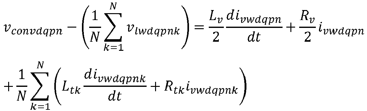

power converter 12 to produce the required AC converter voltage vconv at theAC converter terminal 22;
primary converter controller 34; and
converter reactance 32 and the respective conduit reactances 301, 302, 30N,
with,
ω being the angular frequency of the rotating dq-frame. - The
primary converter controller 34 is additionally programmed to compare the established virtual voltage, i.e. the established virtual voltage vector

power converter 12, i.e. by altering the AC converter voltage vector vconvdqpn that controls thepower converter 12, to reduce any difference between the established virtual voltage vector and the predetermined virtual voltage reference vector
- In addition, when altering the AC converter voltage vconv produced by the power converter to reduce any difference between the established virtual voltage vector and the predetermined virtual voltage reference vector

primary converter controller 34 is further programmed to take into account: - (i) the voltage difference across the
converter reactance 32, e.g. take intoaccount 

- (ii) a virtual voltage difference that is representative of the plurality of voltage differences across the conduit reactance 301, 302, 30N of each AC transmission conduit AC transmission conduit 241, 242, 24N, and which is commensurate with the average voltage difference across the conduit reactances 301, 302, 30N, e.g. take into account


- Moreover, the
primary converter controller 34 is still further programmed to take into account cross-coupling between the real and imaginary parts of the aforementioned voltage difference and the virtual voltage difference. - Accordingly, the
primary converter controller 34 need on take into account those elements of the respective voltage difference and virtual voltage difference in which cross-coupling is represented, i.e. only take into account
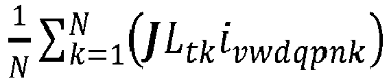
- One way in which the
primary converter controller 34 can be programmed to compare the established virtual voltage vector, i.e.


Figure 2 . - It is noted that in the schematic programming example illustrated in
Figure 2 , theprimary converter controller 34 is additionally programmed to take further account of the predetermined virtual voltage reference vector
AC converter terminal 22, and thereby control each individual AC network voltage v lw1, v lw2, vlwN . - Meanwhile, in the embodiment shown, the
secondary converter controller 36 is programmed, in use, to establish the predetermined virtual voltage reference
primary converter controller 34, i.e. against which theprimary converter controller 34 compares the established virtual voltage vector, i.e.: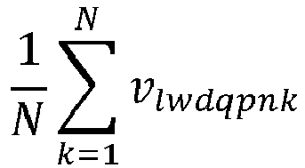
- More particularly, the
second converter controller 36 establishes the virtual voltage reference
- In the embodiment shown, the
secondary converter controller 36 is programmed to achieve this by, firstly, considering whether any AC network voltage v lw1, v lw2, vlwN , i.e. whether any instantaneous average AC networkvoltage 


secondary converter controller 36 modifies the virtual voltage reference vector
- Then, secondly, the
secondary converter controller 36 considers whether any AC network voltage v lw1, v lw2, vlwN , i.e. any instantaneous average AC networkvoltage 


secondary converter controller 36 modifies the virtual voltage reference vector
voltage 


- Additionally, if at least one AC network voltage v lw1, v lw2, vlwN , i.e. at least one instantaneous average AC network
voltage 


voltage 


secondary converter controller 36 is programmed to modify the virtual voltage reference vector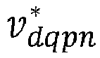

- The
secondary converter controller 36 shown receives, in use, a virtual voltage command
power converter 12, such as a control location. - The
secondary converter controller 36 modifies the virtual voltage reference it establishes, i.e. the virtual voltage reference vector


- One way in which the
secondary converter controller 36 modifies the virtual voltage reference it establishes, i.e. the virtual voltage reference vector


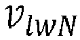
Figure 3 . - As shown in
Figure 3 , after comparing each AC network voltage v lw1, v lw2, vlwN , i.e. each instantaneous average AC networkvoltage 


secondary converter controller 36 implements an asymmetric proportionalintegral control regime 38 in order to establish the aforementioned re-centring of the AC network voltages v lw1, v lw2, vlwN within the desired voltage ranged defined by voltage minimum Vmin and voltage maximum Vmax limits. - By way of example of the invention in use, the operation of a
power transmission network 100 according to a second embodiment of the invention is illustrated with reference toFigures 4(a) to 4(c) . - The second
power transmission network 100 is very similar to the firstpower transmission network 10 described herein above, and similarly includes apower converter 12. Other identical features, which the secondpower transmission network 100 shares with the firstpower transmission network 10 are also identified by the same reference numerals, i.e. as shown inFigure 4(a) . - However, the
AC converter terminal 22 of thepower converter 12 in the secondpower transmission network 100 is instead electrically connected to only two AC transmission conduits, i.e. only first and second AC transmission conduits 241, 242. - Each such AC transmission conduit 241, 242 is, in turn, connected to a respective first and second AC network element 261, 262 in the form of a respective first and second wind park 281, 282. Each of the first and second wind parks 281, 282 is configured to operate at a corresponding individual first and second AC network voltage v lw1, v lw2.
- Meanwhile, each of the first and second AC transmission conduits 241, 242 includes a corresponding first or second transformer 1021, 1022 which takes the place of the idealised conduit reactance 301, 302, 30N included in the first exemplary
power transmission network 10. - The predetermined voltage minimum Vmin is set at 0.98 pu, i.e. 2% below the nominal normal desired operating voltage, and the predetermined voltage maximum Vmax is set at 1.01 pu, i.e. 1% above the nominal normal desired operating voltage. Between zero and 1 second, the
power converter 12 is charging up such that, as shown inFigure 4(b) , theactual average 104 of the first and second AC network voltages v lw1, v lw2 is increasing. - From 1 second to 2 seconds, power is running through the first and second wind parks 281, 282, and each of the first and second AC network voltages v lw1, v lw2 (represented as corresponding first and second instantaneous average AC network voltages


Figure 4(b) ) is increasing. The averageAC network voltage 104 remains essentially constant and, as shown inFigure 4(c) , the AC converter voltage vconv produced at theAC converter terminal 22 settles down, such that the virtual voltage reference vector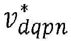
secondary converter controller 36, and used by theprimary converter controller 34 to control the said AC converter voltage vconv, is able also to remain essentially constant. - Between 2 and 3 seconds, the first AC network voltage v lw1, i.e. the corresponding first instantaneous average AC network
voltage 
secondary converter controller 36 acts to reduces the virtual voltage reference vector
primary converter controller 34 reducing the AC converter voltage vector vconvdqpn, which in turn reduces the AC converter voltage vconv produced by thepower converter 12, and thereby reduces the averageAC network voltage 104 to maintain the first AC network voltage v lw1, i.e. the corresponding first instantaneous average AC networkvoltage 
- Normal, safe operating of the second
power transmission network 100 takes place between 3 and 4 seconds, with both the first and second AC network voltages v lw1, v lw2, i.e. the corresponding first and second instantaneous average AC network voltages

AC network voltage 104 remaining essentially constant. - At 4 seconds, the voltage minimum Vmin is artificially set at 1.0 pu, and the
secondary converter controller 36 reacts by increasing the virtual voltage reference vector
primary converter controller 34 to increase the AC converter voltage vconv produced by the power converter 12 (by increasing the AC converter voltage vector vconvdqpn it outputs) which, in turn, increases the averageAC network voltage 104 and thereby lifts the second AC network voltage v lw2, i.e. the corresponding second instantaneous average AC networkvoltage 
- Between 5 and 6 seconds, the second
power transmission network 100 returns again to normal, safe operation. - At 6 seconds, a critical deviation of the first and second AC network voltages v lw1, v lw2, i.e. the corresponding first and second instantaneous average AC network voltages


voltage 
voltage 
second converter controllers power converter 12, and thereby reduce the averageAC network voltage 104 in an effort to maintain the first and second AC network voltages v lw1, v lw2 within the desired voltage range limits set by the voltage maximum Vmax and the voltage minimum Vmin . - Such control by the primary and
second converter controllers secondary converter controller 36 does modify the virtual voltage reference vector


Claims (13)
- A power transmission network (10; 100) comprising a power converter (12) having first and second DC converter terminals (14, 16) for connection in use to a DC network and an AC converter terminal (22) electrically connected to a plurality of AC transmission conduits (241, 242, 24n) each of which is for connection in use to a respective AC network element (261, 262, 26n) configured to operate at a respective individual AC network voltage, the power converter (12) including a primary converter controller (34) programmed in use to control the transfer of power through the power converter (12) and thereby between the DC network and the plurality of AC network elements (261, 262, 26n), and the primary converter controller (34) being further programmed in use to control each individual AC network voltage by establishing a virtual voltage representative of the plurality of AC network voltages and altering a single AC converter voltage produced by the power converter (12) at the AC converter terminal (22) to adjust the virtual voltage and thereby adjust each individual AC network voltage.
- A power transmission network (10; 100) according to Claim 1 wherein the primary converter controller (34) is programmed to establish a virtual voltage commensurate with the average of the individual AC network voltages.
- A power transmission network (10; 100) according to Claim 2 wherein the primary converter controller (34) is programmed to establish the virtual voltage in a vector form having real and imaginary parts.
- A power transmission network (10; 100) according to any preceding claim wherein the primary converter controller (34) is additionally programmed to compare the established virtual voltage with a predetermined virtual voltage reference and to alter the AC converter voltage produced by the power converter (12) to reduce any difference between the established virtual voltage and the predetermined virtual voltage reference.
- A power transmission network (10) according to Claim 4 wherein when altering the AC converter voltage produced by the power converter (12) to reduce any difference between the established virtual voltage and the predetermined virtual voltage reference, the primary converter controller (34) takes into account:(i) a voltage difference across a converter reactance (32); and(ii) a virtual voltage difference representative of a plurality of voltage differences across a conduit reactance (301, 302, 30n) of each AC transmission conduit (241, 242, 24n).
- A power transmission network (10) according to Claim 5 wherein the virtual voltage difference is commensurate with the average voltage difference across the conduit reactances (301, 302, 30n) of the AC transmission conduits (241, 242, 24n).
- A power transmission network (10) according to Claim 5 or Claim 6, when dependent on Claim 3, wherein the primary converter controller (34) is programmed to take into account cross-coupling between the real and imaginary parts of the voltage difference and the virtual voltage difference.
- A power transmission network (10; 100) according to any of Claims 4 to 7 wherein the power converter (12) further includes a secondary converter controller (36) programmed in use to establish the predetermined virtual voltage reference against which the primary converter controller (34) compares the established virtual voltage.
- A power transmission network (10; 100) according to Claim 8 wherein the second converter controller (36) establishes the virtual voltage reference in a manner aimed at maintaining all of the individual AC network voltages within a desired voltage range.
- A power transmission network (10; 100) according to Claim 9 wherein the secondary converter controller (36):(i) considers whether any AC network voltage is below a predetermined voltage minimum and if one or more AC network voltages is below the voltage minimum modifies the virtual voltage reference to raise the or each errant AC network voltage to be equal to or above the voltage minimum; and(ii) considers whether any AC network voltage is above a predetermined voltage maximum and if one or more AC network voltages is above the voltage maximum modifies the virtual voltage reference to reduce the or each errant AC network voltage to be equal to or below the voltage maximum.
- A power transmission network (10; 100) according to Claim 9 wherein the secondary converter controller (36) receives in use a virtual voltage command from a higher-level controller and modifies the virtual voltage reference it establishes by determining an adjustment factor and applying the adjustment factor to the received virtual voltage command.
- A power transmission network (10; 100) according to Claim 10 or Claim 11 wherein if at least one AC network voltage is below the voltage minimum and at least one AC network voltage is above the voltage maximum, the secondary converter controller (36) is programmed to modify the virtual voltage reference in a manner that equalises the amount the or each said AC network voltage deviates from the corresponding voltage minimum and voltage maximum.
- A method of controlling a power transmission network (10; 100) comprising a power converter (12) having first and second DC converter terminals (14, 16) for connection in use to a DC network and an AC converter terminal (22) electrically connected to a plurality of AC transmission conduits (241, 242, 24n) each of which is for connection in use to a respective AC network element (261, 262, 26n) configured to operate at a respective individual AC network voltage, the power converter (12) including a primary converter controller (34) programmed in use to control the transfer of power through the power converter (12) and thereby between the DC network and the plurality of AC network elements,
the method comprising the steps of:controlling each individual AC network voltage by establishing a virtual voltage representative of the plurality of AC network voltages; andaltering a single AC converter voltage produced by the power converter (12) at the AC converter terminal (22) to adjust the virtual voltage and thereby adjust each individual AC network voltage.
Priority Applications (3)
| Application Number | Priority Date | Filing Date | Title |
|---|---|---|---|
| EP20275149.1A EP3975370B1 (en) | 2020-09-25 | 2020-09-25 | Improvements in or relating to power transmission networks |
| US17/485,246 US12034305B2 (en) | 2020-09-25 | 2021-09-24 | Relating to power transmission networks |
| US17/485,205 US11721978B2 (en) | 2020-09-25 | 2021-09-24 | Switching valve |
Applications Claiming Priority (1)
| Application Number | Priority Date | Filing Date | Title |
|---|---|---|---|
| EP20275149.1A EP3975370B1 (en) | 2020-09-25 | 2020-09-25 | Improvements in or relating to power transmission networks |
Publications (2)
| Publication Number | Publication Date |
|---|---|
| EP3975370A1 true EP3975370A1 (en) | 2022-03-30 |
| EP3975370B1 EP3975370B1 (en) | 2024-07-31 |
Family
ID=72659765
Family Applications (1)
| Application Number | Title | Priority Date | Filing Date |
|---|---|---|---|
| EP20275149.1A Active EP3975370B1 (en) | 2020-09-25 | 2020-09-25 | Improvements in or relating to power transmission networks |
Country Status (2)
| Country | Link |
|---|---|
| US (2) | US12034305B2 (en) |
| EP (1) | EP3975370B1 (en) |
Families Citing this family (1)
| Publication number | Priority date | Publication date | Assignee | Title |
|---|---|---|---|---|
| CN116845926B (en) * | 2023-08-28 | 2024-01-19 | 广东电网有限责任公司珠海供电局 | Multi-port power coordination control method and related device |
Family Cites Families (17)
| Publication number | Priority date | Publication date | Assignee | Title |
|---|---|---|---|---|
| GB2518853B (en) * | 2013-10-02 | 2016-01-27 | Alstom Technology Ltd | Voltage source converter |
| EP2916442B1 (en) * | 2014-03-04 | 2019-07-24 | General Electric Technology GmbH | A voltage source converter |
| CN106471722B (en) * | 2014-05-12 | 2020-09-15 | 通用电器技术有限公司 | Improvements in or related to Chained Transformers |
| DE202014004749U1 (en) * | 2014-06-13 | 2015-09-15 | Aehling, Dr. Jaensch & Dr. Goetz GbR (vertretungsberechtigter Gesellschafter Dr. Malte Jaensch, 74321 Bietigheim-Bissingen) | Electronic circuit for simplified operation of multipoint converters |
| CA2957833C (en) | 2014-08-11 | 2018-04-03 | Abb Schweiz Ag | Method of controlling the switching of a multilevel converter, a controller for a multilevel converter, and a computer program for controlling a converter |
| EP3070806B1 (en) * | 2015-03-19 | 2020-09-23 | General Electric Technology GmbH | Power transmission network |
| EP3278435B1 (en) * | 2015-03-30 | 2023-10-25 | General Electric Technology GmbH | Voltage source converters provided with dc fault control |
| EP3096446A1 (en) * | 2015-05-22 | 2016-11-23 | General Electric Technology GmbH | A method of controlling a converter |
| DK3116085T3 (en) * | 2015-07-07 | 2019-09-09 | Siemens Gamesa Renewable Energy As | Operation of a wind turbine connected to a supply network via a central AC power cable through a network bridge control unit with power and voltage control |
| EP3154144B1 (en) * | 2015-10-06 | 2020-04-22 | General Electric Technology GmbH | Improvements in or relating to direct current distance protection controllers |
| WO2018041358A1 (en) * | 2016-09-01 | 2018-03-08 | Abb Schweiz Ag | Circulating current control in a modular multilevel voltage source converter |
| EP3322062B1 (en) * | 2016-11-09 | 2022-09-07 | General Electric Technology GmbH | Improvements in or relating to power transmission networks |
| US11264917B2 (en) * | 2019-12-12 | 2022-03-01 | Kohler Co. | Interleaved inverter |
| EP3944450B1 (en) * | 2020-07-23 | 2024-02-14 | General Electric Technology GmbH | Improvements in or relating to converter stations |
| EP3965243B1 (en) * | 2020-09-04 | 2025-11-26 | GE Vernova Technology GmbH | Improvements in or relating to bipole power transmission schemes |
| DK4184739T3 (en) * | 2021-11-18 | 2025-06-30 | General Electric Technology Gmbh | IMPROVEMENTS IN OR RELATING TO BIPOLAR POWER TRANSMISSION SYSTEMS |
| EP4254706A1 (en) * | 2022-03-29 | 2023-10-04 | General Electric Technology GmbH | Improvements in or relating to bipole power transmission networks |
-
2020
- 2020-09-25 EP EP20275149.1A patent/EP3975370B1/en active Active
-
2021
- 2021-09-24 US US17/485,246 patent/US12034305B2/en active Active
- 2021-09-24 US US17/485,205 patent/US11721978B2/en active Active
Non-Patent Citations (3)
| Title |
|---|
| BELHAOUANE MOHAMED MOEZ ET AL: "Modeling and Analysis of Modular Multilevel Converters connected to Weak AC Grids", 2019 21ST EUROPEAN CONFERENCE ON POWER ELECTRONICS AND APPLICATIONS (EPE '19 ECCE EUROPE), EPE ASSOCIATION, 3 September 2019 (2019-09-03), XP033665670, DOI: 10.23919/EPE.2019.8915435 * |
| LI YINGBIAO ET AL: "Over-Voltage Suppression Methods for the MMC-VSC-HVDC Wind Farm Integration System", IEEE TRANSACTIONS ON CIRCUITS AND SYSTEMS II: EXPRESS BRIEFS, IEEE, US, vol. 67, no. 2, 15 April 2019 (2019-04-15), pages 355 - 359, XP011769361, ISSN: 1549-7747, [retrieved on 20200128], DOI: 10.1109/TCSII.2019.2911652 * |
| XUAN LI ET AL: "Study on fault ride-through capability of wind farm integration using MMC-HVDC", 2014 INTERNATIONAL CONFERENCE ON POWER SYSTEM TECHNOLOGY, IEEE, 20 October 2014 (2014-10-20), pages 2596 - 2601, XP032711663, DOI: 10.1109/POWERCON.2014.6993531 * |
Also Published As
| Publication number | Publication date |
|---|---|
| US20220103091A1 (en) | 2022-03-31 |
| EP3975370B1 (en) | 2024-07-31 |
| US12034305B2 (en) | 2024-07-09 |
| US11721978B2 (en) | 2023-08-08 |
| US20220102979A1 (en) | 2022-03-31 |
Similar Documents
| Publication | Publication Date | Title |
|---|---|---|
| US9973125B2 (en) | Operating a wind turbine being connected to a utility grid solely via an umbilical AC cable with a network bridge controller performing a power and a voltage control | |
| US6400585B2 (en) | Method and control system for voltage control at a converter station | |
| US6411066B1 (en) | Method to control the flow of active power in a high voltage direct current transmission system and device for the same | |
| US5744877A (en) | Downhole power transmission system | |
| CN101223359B (en) | Power regulation in wind farms | |
| EP3070803B1 (en) | Power transmission network | |
| EP4254706A1 (en) | Improvements in or relating to bipole power transmission networks | |
| JP4101788B2 (en) | Voltage adjusting device and voltage adjusting method | |
| US12009757B2 (en) | Relating to bipole power transmission schemes | |
| EP3116086A1 (en) | Operating a wind turbine being connected to a utility grid both via a hvdc power connection and via an umbilical ac cable with a network bridge controller performing a power and a voltage control | |
| US12034305B2 (en) | Relating to power transmission networks | |
| Hiscock et al. | Voltage regulation at sites with distributed generation | |
| Wang et al. | Modified genetic algorithm approach to design of an optimal PID controller for AC–DC transmission systems | |
| US11476661B2 (en) | Device for controlling a terminal for the compensation of a voltage disturbance | |
| RU2551133C1 (en) | Voltage regulation method at alternating-current electric-traction netware | |
| US12620805B2 (en) | Electrical assembly | |
| US11233476B2 (en) | Method and apparatus for low DC bus voltage ride through | |
| RU2394327C1 (en) | Method to control dc insert power | |
| EP4311062A1 (en) | Improvements in or relating to power transmission networks | |
| JP3820385B2 (en) | Isolated system stabilization method and isolated system stabilization system | |
| EP3840201A1 (en) | Supply current limitation | |
| EP4009467A1 (en) | Improvements in or relating to power transmission networks | |
| CN110140272A (en) | Improvements in or related to the transmission network | |
| US20250167549A1 (en) | Improvements relating to providing grid-forming control of a power converter in power transmission networks | |
| US12525798B2 (en) | Process for controlling isolated microgrids based on power-based control and modified Volt-VAr function methods |
Legal Events
| Date | Code | Title | Description |
|---|---|---|---|
| PUAI | Public reference made under article 153(3) epc to a published international application that has entered the european phase |
Free format text: ORIGINAL CODE: 0009012 |
|
| STAA | Information on the status of an ep patent application or granted ep patent |
Free format text: STATUS: THE APPLICATION HAS BEEN PUBLISHED |
|
| AK | Designated contracting states |
Kind code of ref document: A1 Designated state(s): AL AT BE BG CH CY CZ DE DK EE ES FI FR GB GR HR HU IE IS IT LI LT LU LV MC MK MT NL NO PL PT RO RS SE SI SK SM TR |
|
| STAA | Information on the status of an ep patent application or granted ep patent |
Free format text: STATUS: REQUEST FOR EXAMINATION WAS MADE |
|
| 17P | Request for examination filed |
Effective date: 20220930 |
|
| RBV | Designated contracting states (corrected) |
Designated state(s): AL AT BE BG CH CY CZ DE DK EE ES FI FR GB GR HR HU IE IS IT LI LT LU LV MC MK MT NL NO PL PT RO RS SE SI SK SM TR |
|
| STAA | Information on the status of an ep patent application or granted ep patent |
Free format text: STATUS: EXAMINATION IS IN PROGRESS |
|
| 17Q | First examination report despatched |
Effective date: 20230516 |
|
| P01 | Opt-out of the competence of the unified patent court (upc) registered |
Effective date: 20230522 |
|
| GRAP | Despatch of communication of intention to grant a patent |
Free format text: ORIGINAL CODE: EPIDOSNIGR1 |
|
| RIC1 | Information provided on ipc code assigned before grant |
Ipc: H02M 1/00 20060101ALN20240306BHEP Ipc: H02M 7/68 20060101ALI20240306BHEP Ipc: H02J 3/38 20060101ALI20240306BHEP Ipc: H02J 3/24 20060101ALI20240306BHEP Ipc: H02J 3/36 20060101AFI20240306BHEP |
|
| STAA | Information on the status of an ep patent application or granted ep patent |
Free format text: STATUS: GRANT OF PATENT IS INTENDED |
|
| INTG | Intention to grant announced |
Effective date: 20240411 |
|
| RIN1 | Information on inventor provided before grant (corrected) |
Inventor name: JASIM, OMAR Inventor name: THOUVENIN, MARC Inventor name: LI, JIAQI Inventor name: FREYTES, JULIAN Inventor name: DE PREVILLE, GUILLAUME |
|
| GRAS | Grant fee paid |
Free format text: ORIGINAL CODE: EPIDOSNIGR3 |
|
| GRAA | (expected) grant |
Free format text: ORIGINAL CODE: 0009210 |
|
| STAA | Information on the status of an ep patent application or granted ep patent |
Free format text: STATUS: THE PATENT HAS BEEN GRANTED |
|
| AK | Designated contracting states |
Kind code of ref document: B1 Designated state(s): AL AT BE BG CH CY CZ DE DK EE ES FI FR GB GR HR HU IE IS IT LI LT LU LV MC MK MT NL NO PL PT RO RS SE SI SK SM TR |
|
| REG | Reference to a national code |
Ref country code: CH Ref legal event code: EP Ref country code: GB Ref legal event code: FG4D |
|
| REG | Reference to a national code |
Ref country code: DE Ref legal event code: R096 Ref document number: 602020034805 Country of ref document: DE |
|
| REG | Reference to a national code |
Ref country code: IE Ref legal event code: FG4D |
|
| REG | Reference to a national code |
Ref country code: SE Ref legal event code: TRGR |
|
| REG | Reference to a national code |
Ref country code: NL Ref legal event code: FP |
|
| REG | Reference to a national code |
Ref country code: LT Ref legal event code: MG9D |
|
| PG25 | Lapsed in a contracting state [announced via postgrant information from national office to epo] |
Ref country code: PT Free format text: LAPSE BECAUSE OF FAILURE TO SUBMIT A TRANSLATION OF THE DESCRIPTION OR TO PAY THE FEE WITHIN THE PRESCRIBED TIME-LIMIT Effective date: 20241202 |
|
| REG | Reference to a national code |
Ref country code: AT Ref legal event code: MK05 Ref document number: 1709409 Country of ref document: AT Kind code of ref document: T Effective date: 20240731 |
|
| PG25 | Lapsed in a contracting state [announced via postgrant information from national office to epo] |
Ref country code: PT Free format text: LAPSE BECAUSE OF FAILURE TO SUBMIT A TRANSLATION OF THE DESCRIPTION OR TO PAY THE FEE WITHIN THE PRESCRIBED TIME-LIMIT Effective date: 20241202 |
|
| PG25 | Lapsed in a contracting state [announced via postgrant information from national office to epo] |
Ref country code: NO Free format text: LAPSE BECAUSE OF FAILURE TO SUBMIT A TRANSLATION OF THE DESCRIPTION OR TO PAY THE FEE WITHIN THE PRESCRIBED TIME-LIMIT Effective date: 20241031 |
|
| PG25 | Lapsed in a contracting state [announced via postgrant information from national office to epo] |
Ref country code: PL Free format text: LAPSE BECAUSE OF FAILURE TO SUBMIT A TRANSLATION OF THE DESCRIPTION OR TO PAY THE FEE WITHIN THE PRESCRIBED TIME-LIMIT Effective date: 20240731 Ref country code: GR Free format text: LAPSE BECAUSE OF FAILURE TO SUBMIT A TRANSLATION OF THE DESCRIPTION OR TO PAY THE FEE WITHIN THE PRESCRIBED TIME-LIMIT Effective date: 20241101 Ref country code: FI Free format text: LAPSE BECAUSE OF FAILURE TO SUBMIT A TRANSLATION OF THE DESCRIPTION OR TO PAY THE FEE WITHIN THE PRESCRIBED TIME-LIMIT Effective date: 20240731 |
|
| PG25 | Lapsed in a contracting state [announced via postgrant information from national office to epo] |
Ref country code: BG Free format text: LAPSE BECAUSE OF FAILURE TO SUBMIT A TRANSLATION OF THE DESCRIPTION OR TO PAY THE FEE WITHIN THE PRESCRIBED TIME-LIMIT Effective date: 20240731 |
|
| PG25 | Lapsed in a contracting state [announced via postgrant information from national office to epo] |
Ref country code: LV Free format text: LAPSE BECAUSE OF FAILURE TO SUBMIT A TRANSLATION OF THE DESCRIPTION OR TO PAY THE FEE WITHIN THE PRESCRIBED TIME-LIMIT Effective date: 20240731 |
|
| PG25 | Lapsed in a contracting state [announced via postgrant information from national office to epo] |
Ref country code: AT Free format text: LAPSE BECAUSE OF FAILURE TO SUBMIT A TRANSLATION OF THE DESCRIPTION OR TO PAY THE FEE WITHIN THE PRESCRIBED TIME-LIMIT Effective date: 20240731 Ref country code: IS Free format text: LAPSE BECAUSE OF FAILURE TO SUBMIT A TRANSLATION OF THE DESCRIPTION OR TO PAY THE FEE WITHIN THE PRESCRIBED TIME-LIMIT Effective date: 20241130 |
|
| PG25 | Lapsed in a contracting state [announced via postgrant information from national office to epo] |
Ref country code: HR Free format text: LAPSE BECAUSE OF FAILURE TO SUBMIT A TRANSLATION OF THE DESCRIPTION OR TO PAY THE FEE WITHIN THE PRESCRIBED TIME-LIMIT Effective date: 20240731 |
|
| PG25 | Lapsed in a contracting state [announced via postgrant information from national office to epo] |
Ref country code: RS Free format text: LAPSE BECAUSE OF FAILURE TO SUBMIT A TRANSLATION OF THE DESCRIPTION OR TO PAY THE FEE WITHIN THE PRESCRIBED TIME-LIMIT Effective date: 20241031 Ref country code: ES Free format text: LAPSE BECAUSE OF FAILURE TO SUBMIT A TRANSLATION OF THE DESCRIPTION OR TO PAY THE FEE WITHIN THE PRESCRIBED TIME-LIMIT Effective date: 20240731 |
|
| PG25 | Lapsed in a contracting state [announced via postgrant information from national office to epo] |
Ref country code: RS Free format text: LAPSE BECAUSE OF FAILURE TO SUBMIT A TRANSLATION OF THE DESCRIPTION OR TO PAY THE FEE WITHIN THE PRESCRIBED TIME-LIMIT Effective date: 20241031 Ref country code: PL Free format text: LAPSE BECAUSE OF FAILURE TO SUBMIT A TRANSLATION OF THE DESCRIPTION OR TO PAY THE FEE WITHIN THE PRESCRIBED TIME-LIMIT Effective date: 20240731 Ref country code: NO Free format text: LAPSE BECAUSE OF FAILURE TO SUBMIT A TRANSLATION OF THE DESCRIPTION OR TO PAY THE FEE WITHIN THE PRESCRIBED TIME-LIMIT Effective date: 20241031 Ref country code: LV Free format text: LAPSE BECAUSE OF FAILURE TO SUBMIT A TRANSLATION OF THE DESCRIPTION OR TO PAY THE FEE WITHIN THE PRESCRIBED TIME-LIMIT Effective date: 20240731 Ref country code: IS Free format text: LAPSE BECAUSE OF FAILURE TO SUBMIT A TRANSLATION OF THE DESCRIPTION OR TO PAY THE FEE WITHIN THE PRESCRIBED TIME-LIMIT Effective date: 20241130 Ref country code: HR Free format text: LAPSE BECAUSE OF FAILURE TO SUBMIT A TRANSLATION OF THE DESCRIPTION OR TO PAY THE FEE WITHIN THE PRESCRIBED TIME-LIMIT Effective date: 20240731 Ref country code: GR Free format text: LAPSE BECAUSE OF FAILURE TO SUBMIT A TRANSLATION OF THE DESCRIPTION OR TO PAY THE FEE WITHIN THE PRESCRIBED TIME-LIMIT Effective date: 20241101 Ref country code: FI Free format text: LAPSE BECAUSE OF FAILURE TO SUBMIT A TRANSLATION OF THE DESCRIPTION OR TO PAY THE FEE WITHIN THE PRESCRIBED TIME-LIMIT Effective date: 20240731 Ref country code: ES Free format text: LAPSE BECAUSE OF FAILURE TO SUBMIT A TRANSLATION OF THE DESCRIPTION OR TO PAY THE FEE WITHIN THE PRESCRIBED TIME-LIMIT Effective date: 20240731 Ref country code: BG Free format text: LAPSE BECAUSE OF FAILURE TO SUBMIT A TRANSLATION OF THE DESCRIPTION OR TO PAY THE FEE WITHIN THE PRESCRIBED TIME-LIMIT Effective date: 20240731 Ref country code: AT Free format text: LAPSE BECAUSE OF FAILURE TO SUBMIT A TRANSLATION OF THE DESCRIPTION OR TO PAY THE FEE WITHIN THE PRESCRIBED TIME-LIMIT Effective date: 20240731 |
|
| PG25 | Lapsed in a contracting state [announced via postgrant information from national office to epo] |
Ref country code: DK Free format text: LAPSE BECAUSE OF FAILURE TO SUBMIT A TRANSLATION OF THE DESCRIPTION OR TO PAY THE FEE WITHIN THE PRESCRIBED TIME-LIMIT Effective date: 20240731 Ref country code: SM Free format text: LAPSE BECAUSE OF FAILURE TO SUBMIT A TRANSLATION OF THE DESCRIPTION OR TO PAY THE FEE WITHIN THE PRESCRIBED TIME-LIMIT Effective date: 20240731 Ref country code: RO Free format text: LAPSE BECAUSE OF FAILURE TO SUBMIT A TRANSLATION OF THE DESCRIPTION OR TO PAY THE FEE WITHIN THE PRESCRIBED TIME-LIMIT Effective date: 20240731 |
|
| PG25 | Lapsed in a contracting state [announced via postgrant information from national office to epo] |
Ref country code: EE Free format text: LAPSE BECAUSE OF FAILURE TO SUBMIT A TRANSLATION OF THE DESCRIPTION OR TO PAY THE FEE WITHIN THE PRESCRIBED TIME-LIMIT Effective date: 20240731 Ref country code: MC Free format text: LAPSE BECAUSE OF FAILURE TO SUBMIT A TRANSLATION OF THE DESCRIPTION OR TO PAY THE FEE WITHIN THE PRESCRIBED TIME-LIMIT Effective date: 20240731 |
|
| PG25 | Lapsed in a contracting state [announced via postgrant information from national office to epo] |
Ref country code: CZ Free format text: LAPSE BECAUSE OF FAILURE TO SUBMIT A TRANSLATION OF THE DESCRIPTION OR TO PAY THE FEE WITHIN THE PRESCRIBED TIME-LIMIT Effective date: 20240731 |
|
| PG25 | Lapsed in a contracting state [announced via postgrant information from national office to epo] |
Ref country code: SK Free format text: LAPSE BECAUSE OF FAILURE TO SUBMIT A TRANSLATION OF THE DESCRIPTION OR TO PAY THE FEE WITHIN THE PRESCRIBED TIME-LIMIT Effective date: 20240731 |
|
| REG | Reference to a national code |
Ref country code: CH Ref legal event code: PL |
|
| REG | Reference to a national code |
Ref country code: DE Ref legal event code: R097 Ref document number: 602020034805 Country of ref document: DE |
|
| PG25 | Lapsed in a contracting state [announced via postgrant information from national office to epo] |
Ref country code: LU Free format text: LAPSE BECAUSE OF NON-PAYMENT OF DUE FEES Effective date: 20240925 |
|
| PLBE | No opposition filed within time limit |
Free format text: ORIGINAL CODE: 0009261 |
|
| STAA | Information on the status of an ep patent application or granted ep patent |
Free format text: STATUS: NO OPPOSITION FILED WITHIN TIME LIMIT |
|
| 26N | No opposition filed |
Effective date: 20250501 |
|
| PG25 | Lapsed in a contracting state [announced via postgrant information from national office to epo] |
Ref country code: CH Free format text: LAPSE BECAUSE OF NON-PAYMENT OF DUE FEES Effective date: 20240930 |
|
| PG25 | Lapsed in a contracting state [announced via postgrant information from national office to epo] |
Ref country code: IE Free format text: LAPSE BECAUSE OF NON-PAYMENT OF DUE FEES Effective date: 20240925 |
|
| PGFP | Annual fee paid to national office [announced via postgrant information from national office to epo] |
Ref country code: NL Payment date: 20250820 Year of fee payment: 6 |
|
| PGFP | Annual fee paid to national office [announced via postgrant information from national office to epo] |
Ref country code: DE Payment date: 20250820 Year of fee payment: 6 |
|
| PGFP | Annual fee paid to national office [announced via postgrant information from national office to epo] |
Ref country code: IT Payment date: 20250820 Year of fee payment: 6 |
|
| PGFP | Annual fee paid to national office [announced via postgrant information from national office to epo] |
Ref country code: BE Payment date: 20250820 Year of fee payment: 6 Ref country code: GB Payment date: 20250822 Year of fee payment: 6 |
|
| PGFP | Annual fee paid to national office [announced via postgrant information from national office to epo] |
Ref country code: FR Payment date: 20250820 Year of fee payment: 6 |
|
| PGFP | Annual fee paid to national office [announced via postgrant information from national office to epo] |
Ref country code: SE Payment date: 20250820 Year of fee payment: 6 |
|
| PG25 | Lapsed in a contracting state [announced via postgrant information from national office to epo] |
Ref country code: CY Free format text: LAPSE BECAUSE OF FAILURE TO SUBMIT A TRANSLATION OF THE DESCRIPTION OR TO PAY THE FEE WITHIN THE PRESCRIBED TIME-LIMIT; INVALID AB INITIO Effective date: 20200925 |
|
| PG25 | Lapsed in a contracting state [announced via postgrant information from national office to epo] |
Ref country code: HU Free format text: LAPSE BECAUSE OF FAILURE TO SUBMIT A TRANSLATION OF THE DESCRIPTION OR TO PAY THE FEE WITHIN THE PRESCRIBED TIME-LIMIT; INVALID AB INITIO Effective date: 20200925 |