EP3975328A1 - Terminal block protective cover and battery module including the same - Google Patents
Terminal block protective cover and battery module including the same Download PDFInfo
- Publication number
- EP3975328A1 EP3975328A1 EP21199416.5A EP21199416A EP3975328A1 EP 3975328 A1 EP3975328 A1 EP 3975328A1 EP 21199416 A EP21199416 A EP 21199416A EP 3975328 A1 EP3975328 A1 EP 3975328A1
- Authority
- EP
- European Patent Office
- Prior art keywords
- terminal block
- protective cover
- battery module
- cover
- battery
- Prior art date
- Legal status (The legal status is an assumption and is not a legal conclusion. Google has not performed a legal analysis and makes no representation as to the accuracy of the status listed.)
- Pending
Links
Images


Classifications
-
- H—ELECTRICITY
- H01—ELECTRIC ELEMENTS
- H01M—PROCESSES OR MEANS, e.g. BATTERIES, FOR THE DIRECT CONVERSION OF CHEMICAL ENERGY INTO ELECTRICAL ENERGY
- H01M50/00—Constructional details or processes of manufacture of the non-active parts of electrochemical cells other than fuel cells, e.g. hybrid cells
- H01M50/20—Mountings; Secondary casings or frames; Racks, modules or packs; Suspension devices; Shock absorbers; Transport or carrying devices; Holders
- H01M50/296—Mountings; Secondary casings or frames; Racks, modules or packs; Suspension devices; Shock absorbers; Transport or carrying devices; Holders characterised by terminals of battery packs
-
- H—ELECTRICITY
- H01—ELECTRIC ELEMENTS
- H01M—PROCESSES OR MEANS, e.g. BATTERIES, FOR THE DIRECT CONVERSION OF CHEMICAL ENERGY INTO ELECTRICAL ENERGY
- H01M50/00—Constructional details or processes of manufacture of the non-active parts of electrochemical cells other than fuel cells, e.g. hybrid cells
- H01M50/50—Current conducting connections for cells or batteries
- H01M50/572—Means for preventing undesired use or discharge
- H01M50/574—Devices or arrangements for the interruption of current
- H01M50/581—Devices or arrangements for the interruption of current in response to temperature
-
- H—ELECTRICITY
- H01—ELECTRIC ELEMENTS
- H01M—PROCESSES OR MEANS, e.g. BATTERIES, FOR THE DIRECT CONVERSION OF CHEMICAL ENERGY INTO ELECTRICAL ENERGY
- H01M50/00—Constructional details or processes of manufacture of the non-active parts of electrochemical cells other than fuel cells, e.g. hybrid cells
- H01M50/20—Mountings; Secondary casings or frames; Racks, modules or packs; Suspension devices; Shock absorbers; Transport or carrying devices; Holders
- H01M50/204—Racks, modules or packs for multiple batteries or multiple cells
- H01M50/207—Racks, modules or packs for multiple batteries or multiple cells characterised by their shape
- H01M50/209—Racks, modules or packs for multiple batteries or multiple cells characterised by their shape adapted for prismatic or rectangular cells
-
- H—ELECTRICITY
- H01—ELECTRIC ELEMENTS
- H01M—PROCESSES OR MEANS, e.g. BATTERIES, FOR THE DIRECT CONVERSION OF CHEMICAL ENERGY INTO ELECTRICAL ENERGY
- H01M50/00—Constructional details or processes of manufacture of the non-active parts of electrochemical cells other than fuel cells, e.g. hybrid cells
- H01M50/20—Mountings; Secondary casings or frames; Racks, modules or packs; Suspension devices; Shock absorbers; Transport or carrying devices; Holders
- H01M50/233—Mountings; Secondary casings or frames; Racks, modules or packs; Suspension devices; Shock absorbers; Transport or carrying devices; Holders characterised by physical properties of casings or racks, e.g. dimensions
- H01M50/24—Mountings; Secondary casings or frames; Racks, modules or packs; Suspension devices; Shock absorbers; Transport or carrying devices; Holders characterised by physical properties of casings or racks, e.g. dimensions adapted for protecting batteries from their environment, e.g. from corrosion
-
- H—ELECTRICITY
- H01—ELECTRIC ELEMENTS
- H01M—PROCESSES OR MEANS, e.g. BATTERIES, FOR THE DIRECT CONVERSION OF CHEMICAL ENERGY INTO ELECTRICAL ENERGY
- H01M50/00—Constructional details or processes of manufacture of the non-active parts of electrochemical cells other than fuel cells, e.g. hybrid cells
- H01M50/20—Mountings; Secondary casings or frames; Racks, modules or packs; Suspension devices; Shock absorbers; Transport or carrying devices; Holders
- H01M50/262—Mountings; Secondary casings or frames; Racks, modules or packs; Suspension devices; Shock absorbers; Transport or carrying devices; Holders with fastening means, e.g. locks
-
- H—ELECTRICITY
- H01—ELECTRIC ELEMENTS
- H01M—PROCESSES OR MEANS, e.g. BATTERIES, FOR THE DIRECT CONVERSION OF CHEMICAL ENERGY INTO ELECTRICAL ENERGY
- H01M50/00—Constructional details or processes of manufacture of the non-active parts of electrochemical cells other than fuel cells, e.g. hybrid cells
- H01M50/20—Mountings; Secondary casings or frames; Racks, modules or packs; Suspension devices; Shock absorbers; Transport or carrying devices; Holders
- H01M50/271—Lids or covers for the racks or secondary casings
- H01M50/273—Lids or covers for the racks or secondary casings characterised by the material
-
- H—ELECTRICITY
- H01—ELECTRIC ELEMENTS
- H01M—PROCESSES OR MEANS, e.g. BATTERIES, FOR THE DIRECT CONVERSION OF CHEMICAL ENERGY INTO ELECTRICAL ENERGY
- H01M50/00—Constructional details or processes of manufacture of the non-active parts of electrochemical cells other than fuel cells, e.g. hybrid cells
- H01M50/50—Current conducting connections for cells or batteries
- H01M50/502—Interconnectors for connecting terminals of adjacent batteries; Interconnectors for connecting cells outside a battery casing
- H01M50/505—Interconnectors for connecting terminals of adjacent batteries; Interconnectors for connecting cells outside a battery casing comprising a single busbar
-
- H—ELECTRICITY
- H01—ELECTRIC ELEMENTS
- H01M—PROCESSES OR MEANS, e.g. BATTERIES, FOR THE DIRECT CONVERSION OF CHEMICAL ENERGY INTO ELECTRICAL ENERGY
- H01M50/00—Constructional details or processes of manufacture of the non-active parts of electrochemical cells other than fuel cells, e.g. hybrid cells
- H01M50/50—Current conducting connections for cells or batteries
- H01M50/543—Terminals
-
- H—ELECTRICITY
- H01—ELECTRIC ELEMENTS
- H01M—PROCESSES OR MEANS, e.g. BATTERIES, FOR THE DIRECT CONVERSION OF CHEMICAL ENERGY INTO ELECTRICAL ENERGY
- H01M2200/00—Safety devices for primary or secondary batteries
- H01M2200/10—Temperature sensitive devices
-
- Y—GENERAL TAGGING OF NEW TECHNOLOGICAL DEVELOPMENTS; GENERAL TAGGING OF CROSS-SECTIONAL TECHNOLOGIES SPANNING OVER SEVERAL SECTIONS OF THE IPC; TECHNICAL SUBJECTS COVERED BY FORMER USPC CROSS-REFERENCE ART COLLECTIONS [XRACs] AND DIGESTS
- Y02—TECHNOLOGIES OR APPLICATIONS FOR MITIGATION OR ADAPTATION AGAINST CLIMATE CHANGE
- Y02E—REDUCTION OF GREENHOUSE GAS [GHG] EMISSIONS, RELATED TO ENERGY GENERATION, TRANSMISSION OR DISTRIBUTION
- Y02E60/00—Enabling technologies; Technologies with a potential or indirect contribution to GHG emissions mitigation
- Y02E60/10—Energy storage using batteries
Definitions
- the following disclosure relates to a terminal block protective cover and a battery module including the same, and more particularly, to a terminal block protective cover capable of preventing a short circuit in a thermal runaway situation and a battery module including the same.
- one or more battery modules is constituted by connecting a plurality of battery cells in series or in parallel to obtain high output as illustrated in FIG. 1 , and the respective battery modules are electrically connected through a bus bar.
- a pair of terminal blocks having different poles is provided in the battery module, and both ends of the bus bar are respectively connected to terminal blocks of different battery modules, so that the respective battery modules are electrically connected.
- the terminal block portion of the battery module is provided in a structure for preventing a touch by additionally mounting a terminal block protective cover made of a plastic material.
- a temperature of the battery pack increases due to internal or external causes of the battery pack, the increase in temperature causes an increase in current, a thermal runaway, which is a chain reaction in which the increase in current causes the increase in temperature of the battery pack again, may occur, and in a thermal runaway situation, the temperature of the battery pack becomes high enough to approach 600 degrees Celsius.
- metals inside the battery pack are affected by a high-temperature environment to generate metal particles, and the generated metal particles are sprayed in all directions inside the battery pack.
- the terminal block protective cover made of the plastic material is also burned and melted in the high-temperature environment, so that contact portions between both ends of the bus bar and the terminal block are exposed to the outside, and when the metal particles are introduced into the exposed contact portions, a short may occur, which may cause a short circuit and a fire.
- Patent Document 1 Korea Patent Laid-Open Publication No. 10-2016-0107583 ("cell cover for secondary battery and battery module including the same")
- An embodiment of the present disclosure is to provide a terminal block protective cover and a battery module capable of preventing a short circuit phenomenon by protecting a contact portion between a terminal block and a bus bar in a thermal runaway situation.
- an embodiment of the present disclosure is to provide a terminal block protective cover and battery module capable of suppressing exposure of a bus bar to the outside in a thermal runaway situation.
- an embodiment of the present disclosure is to provide a battery module having a structure in which a terminal block protective cover is more easily mounted.
- an embodiment of the present disclosure is to provide a battery module having a structure capable of insulating a fastening portion of an end plate.
- an object of the present disclosure is not limited to the above-mentioned objects. That is, other objects that are not mentioned may be obviously understood from the following specification.
- a battery module includes: a battery cell stack in which a plurality of battery cells are stacked; a terminal block electrically connected to the battery cell stack; a housing accommodating the battery cell stack; an insulating cover covering an opening of the housing and having a terminal block through hole exposing the terminal block to an outside and being formed on one side of the insulating cover ; and a terminal block protective cover accommodating the terminal block exposed to the outside, the terminal block protective cover being melted at a predetermined temperature and insulating the terminal block by covering the terminal block.
- the terminal block protective cover may include a coupling protrusion extending in one direction, a coupling slot may be formed in the insulating cover, and the coupling protrusion may be coupled to the coupling slot by sliding on the coupling slot.
- the insulating cover may further include shielding plates formed on one side and the other side of the terminal block exposed to the outside through the terminal block through hole.
- the terminal block protective cover may further include a melting portion accommodated in the shielding plates and a detachable protrusion protruding outwardly from one side of the melting portion, and the shielding plates further comprising a detachable hole into which the detachable protrusion is inserted.
- the battery module may further include a protective cover coupled to the outside of the insulating cover, the protective cover being formed with a cut-out hole to expose the terminal block to the outside through the cut-out hole at the time of coupling and being formed with a bolt hole for inserting a bolt for coupling with the insulating cover, wherein the terminal block protective cover includes: a terminal block protective portion accommodating the terminal block, and a bolt hole cover portion extending from the terminal block protective portion and covering an upper end of the bolt hole.
- a bolt insulating member inserted into the bolt hole, made of an insulating material, and surrounding an outer periphery of a bolt inserted into the bolt hole may be inserted into the protective cover.
- the terminal block protective cover may include an outer shape portion accommodating the terminal block, and a melting portion protruding from a surface of the outer shape portion opposite to an upper surface of the terminal block, and the melting portion may be melted at a first temperature, and the outer shape portion may be melted at a second temperature, which is a temperature higher than the first temperature.
- the outer shape portion and the melting portion may be made of different materials.
- the melting portion may have a thickness thinner than a thickness of the outer shape portion.
- a battery pack including a terminal block protective cover includes: a plurality of battery modules; and a bus bar having both ends and electrically connecting the battery modules by connecting the both ends to terminal blocks of the battery modules.
- FIG. 2 is a perspective view of a battery module including a terminal block protective cover according to an embodiment of the present disclosure.
- a battery pack including a terminal block protective cover according to an embodiment of the present disclosure includes a structure in which a plurality of battery modules 10 are accommodated in a battery pack case, and the battery modules 10 disposed to be adjacent to each other are electrically connected to each other by connecting one end of a bus bar 20 to a terminal block provided on each battery module 10, as illustrated in FIG. 2 .
- the battery module 10 including the terminal block protective cover according to an embodiment of the present disclosure mainly includes a battery cell stack, a bus bar frame 100, a terminal block 200, a housing 300, an insulating cover 400, a protective cover 500, and a terminal block protective cover 600.
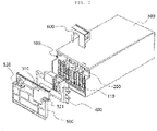
- FIG. 3 is an exploded perspective view of the battery module including a terminal block protective cover according to an embodiment of the present disclosure. A detailed configuration of the battery module 10 including a terminal block protective cover according to an embodiment of the present disclosure will be described with reference to FIG. 3 .
- the battery cell stack has a structure in which a plurality of battery cells are mutually stacked in one direction so that the plurality of battery cells may be electrically connected to each other.
- the battery cell may be formed of a pouch-type secondary battery.
- the battery cell may include an electrode assembly, a battery case, and an electrode lead 110.
- the electrode assembly may include a cathode plate, an anode plate, and a separator.
- a pair of electrode leads 110 may be provided in one battery cell, and may be electrically connected to the electrode assembly.
- the bus bar frame 100 serves to electrically connect the electrode leads 110 provided in the plurality of battery cells.
- a pair of bus bar frames 100 is provided, and each of the bus bar frames 100 is coupled to cover one side and the other side of the battery cell stack.
- the terminal block 200 is provided on one side of the bus bar frame 100.
- the terminal block 200 is electrically connected to the battery cell stack through at least one of the electrode leads 110.
- the terminal block 200 is formed of a copper or aluminum material.
- the housing 300 has a rigidity of a certain level or more.
- the housing 300 is formed to surround an outer surface of the battery cell stack to which the bus bar frame 100 is coupled except for both sides to which the bus bar frame 100 is coupled, so that the battery cell stack is accommodated.
- the insulating cover 400 is formed to cover the outside of the bus bar frame 100.
- the insulating cover 400 is made of an insulating material, for example, a plastic material to insulate the outside of the bus bar frame 100.
- a terminal block through hole 401 exposing the terminal block 200 to the outside is formed on one side of the insulating cover 400.
- the insulating cover 400 is further provided with shielding plates 410 on both sides of the terminal block through hole 401. That is, the terminal block 200 exposed to the outside through the terminal block through hole 401 is accommodated in a pair of shielding plates 410 and serves to primarily prevent metal particles that may occur in a thermal runaway situation from being introduced into the terminal block 200.
- the shielding plates 410 are preferably formed to be sufficiently longer in a vertical direction than a range in which the terminal block 200 is exposed.
- the shielding plates 410 may be further formed with a detachable hole 411 that is in contact with the terminal block through hole 401 and formed to be connected to the terminal block through hole 401.
- the detachable hole 411 is a configuration into which a detachable protrusion 616 of a terminal block protective cover 600 to be described later is inserted. A description thereof will be provided later in more detail when describing a shape of the terminal block protective cover.
- the shielding plates 410 may be formed with a coupling slot 412 elongated in a vertical direction along a front end surface of the shielding plates 410 and a coupling slot 412 along an upper surface of the shielding plates 410.
- the coupling slot 412 is configured to enable sliding coupling of the terminal block protective cover 600 to be described later.
- the coupling slot 412 is configured to more firmly cover the terminal block when the terminal block protective cover 600 is coupled.
- the coupling slot 412 may also be formed in a section between the pair of shielding plates 410 among the upper surfaces of the insulating cover 400.
- the coupling slots 412 formed on each of the shielding plates 410 and the upper surface of the insulating cover 400 may be formed to be in contact with each other and connected to each other.
- a support 420 formed parallel to the terminal block is further formed below the terminal block 200 to connect the pair of shielding plates 410 to each other.
- the support 420 serves to maintain a constant distance between the two shielding plates 410 and to supplement a mechanical rigidity of the shielding plates 410.
- the support 420 may be preferably formed to be in contact with a lower surface of the terminal block 200.
- FIG. 5 is an assembly view of the battery module including the terminal block protective cover according to an embodiment of the present disclosure.
- the protective cover 500 is configured to be coupled to the outside of the insulating cover 400 to provide a rigidity of a certain level or more to the outside of the insulating cover 400.
- a protective cover 500 is made of an aluminum material in order to provide a rigidity of a certain level or more.
- a cut-out hole 510 is formed on one side of the protective cover 500. The pair of shielding plates 410 formed on the insulating cover 400 and the terminal block 200 are exposed to the outside of the protective cover 500 through the cut-out hole 510.
- the protective cover 500 is provided with at least one pair of bolt holes 520.
- a separately provided bolt penetrates through the bolt hole 520 and is fastened to a fastening portion (not illustrated) provided on one side of the housing to fix the protective cover.
- the bolt hole 520 may be further provided with a bolt insulating member 521 made of an insulating material and inserted into the bolt hole 520 to surround an outer periphery of the bolt and an upper surface of the bolt hole 520 in a predetermined section.
- FIG. 6 is a perspective view of a terminal block protective cover according to an embodiment of the present disclosure
- FIG. 7 is a rear bottom perspective view of the terminal block protective cover according to an embodiment of the present disclosure
- FIG. 8 is a bottom view of the terminal block protective cover according to an embodiment of the present disclosure.
- the terminal block protective cover 600 is coupled to the insulating cover 400 exposed to the outside through the cut-out hole 510 to accommodate the terminal block 200.
- the terminal block protective cover 600 is made of an insulating material having high temperature and heat resistance, and may be made of, for example, ethylene propylene diene monomer (EPDM), MICA, glass tape, glass wool, aerogel, urethane, or thermo plastic elastomer (TPE).
- the terminal block protective cover 600 is most preferably made of a TPE material. The terminal block protective cover 600 is melted in a situation of a certain temperature or higher to cover and insulate the outer surface of the terminal block.
- the terminal block protective cover 600 is generally divided into a terminal block protective portion 610 accommodating the terminal block 200, and a bolt hole cover portion 630 extending from the terminal block protective portion 610 and covering an upper end of the bolt hole 520 located on the side closest to the terminal block 200.
- the terminal block protective portion 610 includes an outer shape portion 611, a coupling protrusion 617, and a melting portion 613 formed of a rib and melted at a certain temperature or higher.
- the outer shape portion 611 forms the outermost side of the terminal block protective portion 610 while at the same time secondarily preventing metal particles, which may occur in a thermal runaway situation, from being introduced into the terminal block 200.
- the outer shape portion 611 formed to accommodate the terminal block is formed in a bucket shape in which an opening is disposed to face downward.
- a lower end portion thereof is accommodated in the coupling slot 412 formed on the upper surfaces of the two shielding plates 410 of the insulating cover 400.
- the lower end of the outer shape portion 611 is formed to correspond to the coupling slot 412 so as to be fitted into the coupling slot 412.
- a rear side surface of the lower end of the outer shape portion 611 that is, a surface on a side disposed to face an outer side surface of the insulating cover 400, is accommodated in the coupling slot 412 formed in the section between the pair of shielding plates 410 among the upper surfaces of the insulating cover 400.
- a surface on the front side of the outer shape portion is formed to extend by a predetermined length downward without a separate coupling element to at least partially close the section between the shielding plates 410.
- a lower end of the surface on the front side of the outer shape portion is located above the terminal block 200, so that a predetermined gap is formed between the lower end of the surface on the front side of the outer shape portion and the support 420.
- the gap is a gap for the other end of the bus bar connected to the terminal block 200 to be exposed to the outside of the terminal block protective cover 600, but in a thermal runaway situation, there is a concern that the occurred metal particles may be introduced into the terminal block 200 through the gap.
- a guide plate 612 as illustrated in FIG. 6 is additionally formed at an end portion on the front side of the outer shape portion.
- the guide plate 612 is formed to externally extend from the end portion of the front side of the outer shape portion to be inclined downward, and serves to guide the bus bar exposed through the gap downward and at the same time cover the gap.
- An angle of the guide plate 612 is formed from 10 degrees to 50 degrees, preferably from 10 degrees to 45 degrees, and most preferably from 10 degrees to 30 degrees with respect to the front surface of the outer shape portion.
- FIG. 9 is a cross-sectional view taken along line A-A' of FIG. 2 .
- each coupling protrusion 617 is formed to be inserted into the coupling slot 412 formed on the front side surface of the shielding plate 410 when coupled to the insulating cover 400. That is, the terminal block protective cover 600 may be coupled simply through sliding through the configuration of the coupling slots 412 and the coupling protrusions 617.
- the melting portion 613 includes a first melting portion 614 protruding from a portion opposite to the upper surface of the terminal block inside the outer shape portion 611, and a second melting portion 615 protruding from an inner upper surface of the outer shape portion 611 and in contact with an inner side surface of the shielding plates 410.
- the second melting portion 615 thirdly prevents the metal particles that may occur in a thermal runaway situation from being introduced into the terminal block 200.
- a detachable protrusion 616 in the form of a wide top and narrow bottom is outwardly formed on one side of a lower end of the second melting portion 615, and is inserted into the detachable hole 411 of the shielding plates 410 to prevent the terminal block protective cover 600 from being easily separated from the insulating cover 400.
- FIG. 10 illustrates a cross section of FIG. 9 in a state in which the melting portion is melted.
- the melting portion 613 is melted at a first temperature
- the outer shape portion 611 is melted at a second temperature that is higher than the first temperature.
- the melting portion 613 may be first melted by forming the outer shape portion 611 and the melting portion 613 of different materials, or forming a thickness of the melting portion 613 to be thinner than a thickness of the outer shape portion 611 even if the outer shape portion 611 and the melting portion 613 are formed of the same material.
- the melting portion 613 is formed to be melted before the outer shape portion 611, the outer shape portion 611 in a situation of the first temperature allows the melted melting portion 613 to first insulate the upper surface of the terminal block 200 inside the outer shape portion 611 as illustrated in FIG. 10 .
- This has an effect that even if the melted outer shape portion 611 flows to the outside of the shielding plates 410 and disappears at the time of melting the outer shape portion 611, the first melted melting portion 613 protects the terminal block 200 to prevent the metal particles from being in contact with the terminal block 200.
- the melting portion 613 is appropriately set to have a melting point of about 160 degrees Celsius.
- the bolt hole cover portion 630 is formed to extend from the terminal block protective portion 610 to cover the upper end of the bolt hole 520 located on the side closest to the terminal block 200.
- a bolt groove 633 capable of accommodating a head portion of the bolt inserted into the bolt hole 520 is formed in a portion of the lower surface of the bolt hole cover portion 630 opposite to the bolt hole 520.
- a plate-shaped extension 631 extending downward along a periphery of a lower end of the bolt hole cover portion 630 may be further formed around the lower end of the bolt hole cover portion 630.
- the battery module including the terminal block protective cover for preventing the short circuit of the present disclosure having such a configuration may insulate the terminal block in a thermal runaway situation through the configuration of the terminal block protective cover.
- the outer shape portion may effectively insulate the terminal block by limiting an accommodating position of the melting portion, which is melted before the outer shape portion and is in a liquid state, to the upper surface of the terminal block.
- the assembly operation of the terminal block protective cover may be more easily performed through the configuration of the coupling protrusion and the coupling slot.
Landscapes
- Chemical & Material Sciences (AREA)
- Chemical Kinetics & Catalysis (AREA)
- Electrochemistry (AREA)
- General Chemical & Material Sciences (AREA)
- Connection Of Batteries Or Terminals (AREA)
- Battery Mounting, Suspending (AREA)
Applications Claiming Priority (1)
| Application Number | Priority Date | Filing Date | Title |
|---|---|---|---|
| KR1020200127070A KR20220043543A (ko) | 2020-09-29 | 2020-09-29 | 단자대 보호 커버 및 이를 포함하는 배터리모듈 |
Publications (1)
| Publication Number | Publication Date |
|---|---|
| EP3975328A1 true EP3975328A1 (en) | 2022-03-30 |
Family
ID=77998877
Family Applications (1)
| Application Number | Title | Priority Date | Filing Date |
|---|---|---|---|
| EP21199416.5A Pending EP3975328A1 (en) | 2020-09-29 | 2021-09-28 | Terminal block protective cover and battery module including the same |
Country Status (4)
| Country | Link |
|---|---|
| US (1) | US20220102804A1 (zh) |
| EP (1) | EP3975328A1 (zh) |
| KR (1) | KR20220043543A (zh) |
| CN (1) | CN114335923A (zh) |
Families Citing this family (2)
| Publication number | Priority date | Publication date | Assignee | Title |
|---|---|---|---|---|
| WO2023229450A1 (ko) * | 2022-05-23 | 2023-11-30 | 주식회사 엘지에너지솔루션 | 배터리 모듈 |
| KR20240044683A (ko) * | 2022-09-29 | 2024-04-05 | 주식회사 엘지에너지솔루션 | 열 전파 방지구조가 개선된 배터리 모듈 |
Citations (5)
| Publication number | Priority date | Publication date | Assignee | Title |
|---|---|---|---|---|
| EP1239506A2 (en) * | 2001-03-07 | 2002-09-11 | Yazaki Corporation | Protective cover and fuse box |
| EP2612386A1 (en) * | 2010-09-02 | 2013-07-10 | Bathium Canada Inc. | Connector for battery pack |
| KR20160107583A (ko) | 2015-03-04 | 2016-09-19 | 주식회사 엘지화학 | 이차 전지용 셀 커버 및 이를 포함하는 배터리 모듈 |
| EP3629395A1 (en) * | 2018-09-28 | 2020-04-01 | Contemporary Amperex Technology Co., Limited | Terminal protection cover and battery module |
| US20200176727A1 (en) * | 2016-09-26 | 2020-06-04 | Nissan Motor Co., Ltd. | Assembly including unit cell and spacer |
Family Cites Families (6)
| Publication number | Priority date | Publication date | Assignee | Title |
|---|---|---|---|---|
| WO2011145609A1 (ja) * | 2010-05-19 | 2011-11-24 | 日産自動車株式会社 | 双極型二次電池 |
| KR101297176B1 (ko) * | 2010-06-03 | 2013-08-21 | 주식회사 엘지화학 | 신규한 구조의 전지모듈 |
| JP4939643B1 (ja) * | 2010-11-09 | 2012-05-30 | 三菱重工業株式会社 | 電池モジュール |
| TWI628831B (zh) * | 2013-08-30 | 2018-07-01 | 睿能創意公司 | 具有熱失控減緩的可攜式電能儲存裝置 |
| KR102065106B1 (ko) * | 2015-12-18 | 2020-01-10 | 주식회사 엘지화학 | 이차전지 팩 |
| KR20210072513A (ko) * | 2019-12-09 | 2021-06-17 | 주식회사 엘지에너지솔루션 | 모듈과 팩 케이스 사이에 절연부재가 개재된 전지팩 |
-
2020
- 2020-09-29 KR KR1020200127070A patent/KR20220043543A/ko unknown
-
2021
- 2021-09-26 CN CN202111126309.1A patent/CN114335923A/zh active Pending
- 2021-09-27 US US17/486,135 patent/US20220102804A1/en active Pending
- 2021-09-28 EP EP21199416.5A patent/EP3975328A1/en active Pending
Patent Citations (5)
| Publication number | Priority date | Publication date | Assignee | Title |
|---|---|---|---|---|
| EP1239506A2 (en) * | 2001-03-07 | 2002-09-11 | Yazaki Corporation | Protective cover and fuse box |
| EP2612386A1 (en) * | 2010-09-02 | 2013-07-10 | Bathium Canada Inc. | Connector for battery pack |
| KR20160107583A (ko) | 2015-03-04 | 2016-09-19 | 주식회사 엘지화학 | 이차 전지용 셀 커버 및 이를 포함하는 배터리 모듈 |
| US20200176727A1 (en) * | 2016-09-26 | 2020-06-04 | Nissan Motor Co., Ltd. | Assembly including unit cell and spacer |
| EP3629395A1 (en) * | 2018-09-28 | 2020-04-01 | Contemporary Amperex Technology Co., Limited | Terminal protection cover and battery module |
Also Published As
| Publication number | Publication date |
|---|---|
| KR20220043543A (ko) | 2022-04-05 |
| US20220102804A1 (en) | 2022-03-31 |
| CN114335923A (zh) | 2022-04-12 |
Similar Documents
| Publication | Publication Date | Title |
|---|---|---|
| EP3975328A1 (en) | Terminal block protective cover and battery module including the same | |
| KR102036085B1 (ko) | 이차 전지 모듈 | |
| EP2315293B1 (en) | Battery pack | |
| US9923183B2 (en) | Busbar module | |
| KR101932283B1 (ko) | 배터리 유닛 | |
| US11050111B2 (en) | Battery module and protecting assembly thereof | |
| WO2018194296A1 (ko) | 배터리 모듈 | |
| US7701170B2 (en) | Secondary battery pack with frame for battery mounting | |
| KR102160342B1 (ko) | 일체형 버스바를 구비한 에너지저장용 배터리팩 | |
| US20050140338A1 (en) | Lead member and secondary battery module with the same | |
| CN112993458A (zh) | 电池模块 | |
| US9748533B2 (en) | Battery module | |
| KR20170022371A (ko) | 이차 전지 모듈 | |
| EP4020690A1 (en) | Pouch type battery cell and battery pack including the same | |
| KR102116187B1 (ko) | 개선된 셀홀더를 구비한 에너지저장용 배터리팩 | |
| US20220311101A1 (en) | Battery pack | |
| US7531985B2 (en) | Pack case for secondary battery | |
| EP3961792A1 (en) | Battery module and battery pack including same | |
| KR20220023720A (ko) | 열 수축 필름이 적용된 배터리 모듈, 그리고 이를 포함하는 배터리 팩 및 자동차 | |
| KR20220118636A (ko) | 배터리 팩 | |
| WO2019124749A1 (ko) | 전지 모들 및 이를 포함하는 전지팩 | |
| US20230344086A1 (en) | Battery module | |
| US20230178845A1 (en) | Flame blocking unit and battery pack | |
| US20230231277A1 (en) | Battery pack | |
| US20230089745A1 (en) | Battery pack |
Legal Events
| Date | Code | Title | Description |
|---|---|---|---|
| PUAI | Public reference made under article 153(3) epc to a published international application that has entered the european phase |
Free format text: ORIGINAL CODE: 0009012 |
|
| STAA | Information on the status of an ep patent application or granted ep patent |
Free format text: STATUS: REQUEST FOR EXAMINATION WAS MADE |
|
| 17P | Request for examination filed |
Effective date: 20210928 |
|
| AK | Designated contracting states |
Kind code of ref document: A1 Designated state(s): AL AT BE BG CH CY CZ DE DK EE ES FI FR GB GR HR HU IE IS IT LI LT LU LV MC MK MT NL NO PL PT RO RS SE SI SK SM TR |
|
| RAP1 | Party data changed (applicant data changed or rights of an application transferred) |
Owner name: SK ON CO., LTD. |
|
| P01 | Opt-out of the competence of the unified patent court (upc) registered |
Effective date: 20230602 |