EP3975219A1 - Electromagnetic operation device - Google Patents
Electromagnetic operation device Download PDFInfo
- Publication number
- EP3975219A1 EP3975219A1 EP19930085.6A EP19930085A EP3975219A1 EP 3975219 A1 EP3975219 A1 EP 3975219A1 EP 19930085 A EP19930085 A EP 19930085A EP 3975219 A1 EP3975219 A1 EP 3975219A1
- Authority
- EP
- European Patent Office
- Prior art keywords
- unit
- electromagnetic
- power
- opening
- connection means
- Prior art date
- Legal status (The legal status is an assumption and is not a legal conclusion. Google has not performed a legal analysis and makes no representation as to the accuracy of the status listed.)
- Granted
Links
Images

Classifications
-
- H—ELECTRICITY
- H01—ELECTRIC ELEMENTS
- H01H—ELECTRIC SWITCHES; RELAYS; SELECTORS; EMERGENCY PROTECTIVE DEVICES
- H01H33/00—High-tension or heavy-current switches with arc-extinguishing or arc-preventing means
- H01H33/02—Details
- H01H33/59—Circuit arrangements not adapted to a particular application of the switch and not otherwise provided for, e.g. for ensuring operation of the switch at a predetermined point in the AC cycle
-
- H—ELECTRICITY
- H01—ELECTRIC ELEMENTS
- H01F—MAGNETS; INDUCTANCES; TRANSFORMERS; SELECTION OF MATERIALS FOR THEIR MAGNETIC PROPERTIES
- H01F7/00—Magnets
- H01F7/06—Electromagnets; Actuators including electromagnets
- H01F7/064—Circuit arrangements for actuating electromagnets
-
- H—ELECTRICITY
- H01—ELECTRIC ELEMENTS
- H01H—ELECTRIC SWITCHES; RELAYS; SELECTORS; EMERGENCY PROTECTIVE DEVICES
- H01H33/00—High-tension or heavy-current switches with arc-extinguishing or arc-preventing means
- H01H33/02—Details
- H01H33/28—Power arrangements internal to the switch for operating the driving mechanism
- H01H33/38—Power arrangements internal to the switch for operating the driving mechanism using electromagnet
-
- H—ELECTRICITY
- H01—ELECTRIC ELEMENTS
- H01H—ELECTRIC SWITCHES; RELAYS; SELECTORS; EMERGENCY PROTECTIVE DEVICES
- H01H33/00—High-tension or heavy-current switches with arc-extinguishing or arc-preventing means
- H01H33/60—Switches wherein the means for extinguishing or preventing the arc do not include separate means for obtaining or increasing flow of arc-extinguishing fluid
- H01H33/66—Vacuum switches
- H01H33/666—Operating arrangements
- H01H33/6662—Operating arrangements using bistable electromagnetic actuators, e.g. linear polarised electromagnetic actuators
Definitions
- the present disclosure relates to an electromagnetic operation device.
- An electromagnetic operation device used as an operation mechanism for an opening/closing device drives a movable core by exciting an electromagnetic coil with power accumulated in a capacitor and opens/closes a contact of the opening/closing device by the force of the drive.
- Such an electromagnetic operation device is required to swiftly restart opening/closing control in an emergency case such as the case of loss of control power.
- a turn-on method for an electromagnetic operation type opening/closing apparatus including: connecting a turn-on power supply to the electromagnetic operation type opening/closing apparatus disposed in a place where there is no power supply; accumulating energy in a capacitor by DC power that is supplied from the turn-on power supply; and performing a turn-on operation of the opening/closing device with the energy accumulated in the capacitor (see, for example, Patent Document 1).
- Patent Document 1 Japanese Laid-Open Patent Publication No. 2005-197122
- Patent Document 1 enables the turn-on operation of the opening/closing device by using the turn-on power supply in a case where, for example, power is not supplied from an ordinary power supply.
- the technique in Patent Document 1 has the following problem. That is, a control board for controlling a current-conduction circuit connecting the capacitor and an electromagnetic coil is physically disposed inside the electromagnetic operation type opening/closing apparatus, and thus, when an abnormality occurs in the control board, it may take time to restart the opening/closing control.
- the present disclosure has been made to solve the above problem, and an object of the present disclosure is to obtain an electromagnetic operation device that enables opening/closing control to be swiftly restarted even when an abnormality occurs in a control board for controlling an opening/closing operation of an opening/closing device.
- An electromagnetic operation device includes: an electromagnetic operation unit connected to a movable side of an opening/closing device and configured to open/close the opening/closing device; a drive power supply unit including a first power supplying means and a first control means configured to control supply of power from the first power supplying means to the electromagnetic operation unit, to control an opening/closing operation of the opening/closing device; an electromagnetic-operation-unit-side circuit connection means provided at an end portion, of a circuit connected to the electromagnetic operation unit, that is located on an opposite side to the electromagnetic operation unit; and a drive-power-supply-unit-side circuit connection means provided at an end portion, of a circuit connected to the drive power supply unit, that is located on an opposite side to the drive power supply unit, the drive-power-supply-unit-side circuit connection means being connected to the electromagnetic-operation-unit-side circuit connection means to form a connection circuit that connects the electromagnetic operation unit and the drive power supply unit, wherein the electromagnetic-operation-unit-side circuit connection means is, in
- the electromagnetic operation device enables opening/closing control to be swiftly restarted even when an abnormality occurs in the control board for controlling the opening/closing operation of the opening/closing device.
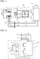
- FIG. 1 is an entire configuration diagram showing an electromagnetic operation device according to embodiment 1 and an opening/closing device to be operated by the electromagnetic operation device.
- An electromagnetic operation device 100 includes: an electromagnetic operation unit 4 which is connected to a movable side of an opening/closing device 1 including therein a vacuum valve 2, and which opens/closes the opening/closing device 1; and a drive power supply unit 12 which supplies power to the electromagnetic operation unit 4.
- the electromagnetic operation unit 4 and the drive power supply unit 12 are connected by a connection circuit that is formed by connecting electromagnetic-operation-unit-side connection circuits 161 and drive-power-supply-unit-side connection circuits 162 as described later. Via each electromagnetic-operation-unit-side connection circuit 161 and the corresponding drive-power-supply-unit-side connection circuit 162, power is supplied from the drive power supply unit 12 to the electromagnetic operation unit 4.
- a fixed core 7 and a movable core 10 are provided, and an opening coil 8a and a closing coil 8b are disposed coaxially with the movable core 10 so as to enclose a part of the movable core 10.
- a permanent magnet 9 for attracting the movable core 10 in a closing direction is provided inside the fixed core 7, and a release spring 11 for urging the movable core 10 in an opening direction is provided on an axially outer side of the fixed core.
- one end of a movable shaft 6 is fixed to the movable core 10.
- the movable shaft 6 extends from the movable core 10 toward the opening/closing device 1, and another end of the movable shaft 6 is connected to one end of an insulating rod 3 via a contact-pressure spring 5.
- the insulating rod 3 extends from the contact-pressure spring 5 to the inside of the vacuum valve 2, and another end of the insulating rod 3 is provided with an electrode.
- the movable core 10 moves in the opening direction and the closing direction owing to electromagnetic forces from the excited opening coil 8a and closing coil 8b. Consequently, an opening operation and a closing operation of the opening/closing device 1 are performed.
- the opening coil 8a and the closing coil 8b are excited by supply of power from the drive power supply unit 12.
- the drive power supply unit 12 includes: a DC power supply 13 which is a first power supplying means; two electromagnetic coil capacitors 15a and 15b in each of which power from the DC power supply 13 is accumulated; and a control board 14 which is a first control means and which is operated by power from the DC power supply 13 and controls a current that flows upon electric discharge by each of the electromagnetic coil capacitors 15a and 15b.
- the control board 14 controls, according to an opening command or a closing command made by a higher-order control device (not shown) or a user input, a current to be supplied from the electromagnetic coil capacitor 15a or 15b to a corresponding one out of the opening coil 8a and the closing coil 8b, to control an opening/closing operation of the opening/closing device 1.
- the electromagnetic coil capacitor 15a corresponds to the opening coil 8a, and a current from the electromagnetic coil capacitor 15a is supplied to the opening coil 8a.
- the electromagnetic coil capacitor 15b corresponds to the closing coil 8b, and a current from the electromagnetic coil capacitor 15b is supplied to the closing coil 8b.
- the electromagnetic-operation-unit-side connection circuits 161 include at least a circuit corresponding to the opening coil 8a and a circuit corresponding to the closing coil 8b
- the drive-power-supply-unit-side connection circuits 162 also include at least a circuit corresponding to the opening coil 8a and a circuit corresponding to the closing coil 8b.
- the electromagnetic-operation-unit-side connection circuits 161 are connected to the opening coil 8a and the closing coil 8b of the electromagnetic operation unit 4, and electromagnetic-operation-unit-side circuit connection means 16a1 and 16b1 are each provided at an end portion, of the corresponding one of the electromagnetic-operation-unit-side connection circuits 161, that is located on an opposite side to the electromagnetic operation unit 4.
- the drive-power-supply-unit-side connection circuits 162 are connected to the control board 14 of the drive power supply unit 12, and drive-power-supply-unit-side circuit connection means 16a2 and 16b2 are each provided at an end portion, of the corresponding one of the drive-power-supply-unit-side connection circuits 162, that is located on an opposite side to the drive power supply unit 12.
- the electromagnetic-operation-unit-side circuit connection means 16a1 and the drive-power-supply-unit-side circuit connection means 16a2 correspond to the opening coil 8a and the electromagnetic coil capacitor 15a
- the electromagnetic-operation-unit-side circuit connection means 16b1 and the drive-power-supply-unit-side circuit connection means 16b2 correspond to the closing coil 8b and the electromagnetic coil capacitor 15b.
- the electromagnetic-operation-unit-side connection circuits 161 and the drive-power-supply-unit-side connection circuits 162 are connected to each other by connecting the electromagnetic-operation-unit-side circuit connection means 16a1 and the drive-power-supply-unit-side circuit connection means 16a2 and connecting the electromagnetic-operation-unit-side circuit connection means 16b1 and the drive-power-supply-unit-side circuit connection means 16b2. This leads to formation of a connection circuit that connects the electromagnetic operation unit 4 and the drive power supply unit 12.
- each of the electromagnetic-operation-unit-side circuit connection means 16a1 and 16b1, and the corresponding one of the drive-power-supply-unit-side circuit connection means 16a2 and 16b2 have forms allowing contact and separation therebetween and are, for example, respectively a plug and a receptacle connected to the plug.
- each of the electromagnetic-operation-unit-side circuit connection means 16a1 and 16b1, and the corresponding one of the drive-power-supply-unit-side circuit connection means can be implemented by connectors which are a plug and a receptacle.
- the electromagnetic operation unit 4 and the drive power supply unit 12 are in a state of being connected through the electromagnetic-operation-unit-side connection circuits 161 and the drive-power-supply-unit-side connection circuits 162, and the drive power supply unit 12 supplies power to the opening coil 8a and the closing coil 8b and performs opening/closing control for the opening/closing device 1.
- FIG. 2 is a configuration diagram of an emergency operation device according to embodiment 1.
- the "emergency case” refers to a situation in which it has become impossible to supply power from the drive power supply unit 12 to the electromagnetic operation unit 4.
- Examples of the emergency case include: a case where power from the DC power supply 13 is lost; a case where the control board 14 malfunctions; a case where the electromagnetic coil capacitors 15a and 15b malfunction; a case where the drive-power-supply-unit-side connection circuits 162 between the drive power supply unit 12 and the drive-power-supply-unit-side circuit connection means 16a2 and 16b2 are broken; a case where a plurality of the above failures occur; and the like.
- An emergency operation device 121 includes: a power supply unit 20 which is a second power supplying means; two electromagnetic coil capacitors 19a and 19b in each of which power from the power supply unit 20 is accumulated; and a control board 18 which is second control means and which controls a current that flows upon electric discharge by each of the electromagnetic coil capacitors 19a and 19b.
- the power supply unit 20, the electromagnetic coil capacitors 19a and 19b, and the control board 18 are integrated with one another.
- the emergency operation device 121 is of a portable type that allows the emergency operation device 121 to be carried around.
- Emergency-operation-device-side connection circuits 17 are connected to the control board 18.
- Emergency-operation-device-side circuit connection means 17a and 17b that are connectable to the electromagnetic-operation-unit-side circuit connection means 16a1 and 16b1, are each provided at an end portion, of the corresponding one of the emergency-operation-device-side connection circuits 17, that is located on an opposite side to the control board 18.
- the emergency-operation-device-side circuit connection means 17a and 17b are, for example, plugs or receptacles and have the same connector forms as the connector forms of the drive-power-supply-unit-side circuit connection means 16a2 and 16b2 so as to be connectable to the electromagnetic-operation-unit-side circuit connection means 16a1 and 16b1 in the same manner as the drive-power-supply-unit-side circuit connection means 16a2 and 16b2.
- the power supply unit 20 includes: a manual power generator 22 to which a rotary handle 23 is attached and which generates power by rotation of the rotary handle 23; and a control power supply capacitor 21 in which power generated by the manual power generator 22 is accumulated.
- the control board 18 is operated by the power accumulated in the control power supply capacitor 21 and controls a current that is generated upon electric discharge by each of the electromagnetic coil capacitors 19a and 19b.
- FIG. 3 illustrates an entire configuration in a state where the electromagnetic operation unit and the emergency operation device are connected.
- the electromagnetic-operation-unit-side circuit connection means 16a1 and the drive-power-supply-unit-side circuit connection means 16a2 which are in a connected state and the electromagnetic-operation-unit-side circuit connection means 16b1 and the drive-power-supply-unit-side circuit connection means 16b2 which are also in a connected state, are separated from each other first so that the states of electrical connections therebetween are canceled.
- the electromagnetic-operation-unit-side circuit connection means 16a1 and 16b1 and the emergency-operation-device-side circuit connection means 17a and 17b are connected so that supply of power from the emergency operation device 121 to the electromagnetic operation unit 4 is enabled.
- the control board 18 controls, according to an opening command or a closing command made by a higher-order control device (not shown) or a user input, a current to be supplied from the electromagnetic coil capacitors 19a or 19b to a corresponding one out of the opening coil 8a and the closing coil 8b, to restart the opening/closing control for the opening/closing device 1.
- the electromagnetic coil capacitor 19a corresponds to the opening coil 8a, and a current from the electromagnetic coil capacitor 19a is supplied to the opening coil 8a.
- the electromagnetic coil capacitor 19b corresponds to the closing coil 8b, and a current from the electromagnetic coil capacitor 19b is supplied to the closing coil 8b.
- the emergency-operation-device-side connection circuits 17 include at least a circuit corresponding to the opening coil 8a and a circuit corresponding to the closing coil 8b.
- the emergency operation device 121 may include a monitoring means which monitors the level of accumulated power in each of the control power supply capacitor 21 and the electromagnetic coil capacitors 19a and 19b and which generates an alarm if the monitoring means determines that necessary power for the opening/closing control for the opening/closing device 1 has not been accumulated or if there is a heightened probability of experiencing a situation in which the necessary power has not been accumulated. If such a monitoring means is provided, power generation with use of the power supply unit 20 can be performed by a user at an appropriate time, whereby control of the opening/closing operation can be prevented from being stopped owing to insufficiency of power.
- Embodiment 1 enables the opening/closing control to be swiftly restarted even when an abnormality occurs in the control board for controlling the opening/closing operation of the opening/closing device. More specifically, in connection between the electromagnetic operation unit for opening/closing the opening/closing device and the drive power supply unit for controlling supply of power to the electromagnetic operation unit, each electromagnetic-operation-unit-side connection circuit and the corresponding drive-power-supply-unit-side connection circuit are connected to form a connection circuit that connects the electromagnetic operation unit and the drive power supply unit.
- the electromagnetic-operation-unit-side connection circuit and the drive-power-supply-unit-side connection circuit are connected through the electromagnetic-operation-unit-side circuit connection means and the drive-power-supply-unit-side circuit connection means which are provided at the respective end portions.
- an abnormality such as a malfunction occurs in the control board of the drive power supply unit
- the state of connection between the electromagnetic-operation-unit-side circuit connection means and the drive-power-supply-unit-side circuit connection means is canceled, and the emergency operation device including the control board for controlling the opening/closing operation of the opening/closing device is connected to the electromagnetic-operation-unit-side circuit connection means.
- the emergency operation device is connected to the electromagnetic operation unit, and thereafter, the emergency operation device controls the opening/closing operation of the opening/closing device.
- the emergency operation device includes the manual power generator, and thus it is not necessary to prepare any power supply for emergency.
- the opening/closing control can be restarted merely by changing the connection destination for the electromagnetic-operation-unit-side circuit connection means from the drive power supply unit to the emergency operation device. Therefore, even when an abnormality occurs in the control board for controlling the opening/closing operation of the opening/closing device, the opening/closing control can be swiftly restarted.
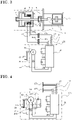
- FIG. 4 is a configuration diagram of an emergency operation device according to embodiment 2.
- An emergency operation device 221 includes: a power supply unit 201; the two electromagnetic coil capacitors 19a and 19b in each of which power from the power supply unit 201 is accumulated; and the control board 18 which controls a current that flows upon electric discharge by each of the electromagnetic coil capacitors 19a and 19b.
- the power supply unit 201 includes, in addition to the components of the power supply unit 20 in embodiment 1, a battery 24 connected in parallel to the manual power generator 22.
- the power supply unit 201 further includes a power supply changing switch 25 which is a power supply changing means between the manual power generator 22 and the control power supply capacitor 21.
- the power supply changing switch 25 enables the connection destination for the control board 18 to be changed between the manual power generator 22 and the battery 24.
- the battery 24 only has to be a DC power supply having an output voltage equal to or higher than a voltage necessary for operation of the control board 18. Examples of the DC power supply include a battery for automobiles, a dry cell, a fuel cell, and the like.
- Embodiment 2 makes it possible to obtain the same advantageous effects as those in embodiment 1.
- the battery is connected in parallel to the manual power generator, and the power supply changing switch which changes, between the manual power generator and the battery, the connection destination for the control circuit is provided.
- the control circuit can be operated more swiftly than in the case of providing only the manual power generator as in embodiment 1. Consequently, the opening/closing control for the opening/closing device can be more swiftly restarted
- FIG. 5 is an entire configuration diagram showing an electromagnetic operation device according to embodiment 3 and the opening/closing device to be operated by the electromagnetic operation device.
- An electromagnetic operation device 300 is different from the electromagnetic operation device 100 according to embodiment 1 in that the electromagnetic-operation-unit-side circuit connection means include: the electromagnetic-operation-unit-side circuit connection means 16a1 and 16b1 which are the first circuit connection means and which correspond to the drive power supply unit 12; and electromagnetic-operation-unit-side circuit connection means 16c1 and 16d1 which are second circuit connection means and which correspond to the emergency operation device 121.
- the electromagnetic-operation-unit-side circuit connection means 16a1, 16b1, 16c1, and 16d1 are connected in parallel to each other.
- the electromagnetic-operation-unit-side circuit connection means 16a1 and 16b1 are connected to the drive-power-supply-unit-side circuit connection means 16a2 and 16b2 in the same manner as in embodiment 1, and the electromagnetic-operation-unit-side circuit connection means 16c1 and 16d1 are connected to the emergency-operation-device-side circuit connection means 17a and 17b. It is noted that the electromagnetic-operation-unit-side circuit connection means 16a1 and 16c1 correspond to the opening coil 8a, and the electromagnetic-operation-unit-side circuit connection means 16b1 and 16d1 correspond to the closing coil 8b.
- Circuit changing switches 26 which are circuit changing means are provided between the electromagnetic operation unit 4 and the electromagnetic-operation-unit-side circuit connection means 16a1, 16b1, 16c1, and 16d1.
- the circuit changing switches 26 are, for example, manual changing switches and change, between the drive power supply unit 12 and the emergency operation device 121, the connection destination for the electromagnetic operation unit 4.
- Embodiment 3 makes it possible to obtain the same advantageous effects as those in embodiment 1.
- the electromagnetic-operation-unit-side circuit connection means include the first circuit connection means corresponding to the drive power supply unit and the second circuit connection means corresponding to the emergency operation device, and the circuit changing switches provided between the electromagnetic operation unit and the electromagnetic-operation-unit-side circuit connection means enable the connection destination for the electromagnetic operation unit to be changed between the drive power supply unit and the emergency operation device.
- connection destination for the electromagnetic operation unit only has to be changed from the drive power supply unit to the emergency operation device by the circuit changing switches, and it is not necessary to separate the drive-power-supply-unit-side circuit connection means from the electromagnetic-operation-unit-side circuit connection means in order to connect the electromagnetic-operation-unit-side circuit connection means and the emergency-operation-device-side circuit connection means. Therefore, connection of the emergency operation device is easy, and the opening/closing control for the opening/closing device can be more swiftly restarted.
Landscapes
- Physics & Mathematics (AREA)
- Electromagnetism (AREA)
- Engineering & Computer Science (AREA)
- Power Engineering (AREA)
- Driving Mechanisms And Operating Circuits Of Arc-Extinguishing High-Tension Switches (AREA)
- Keying Circuit Devices (AREA)
- Safety Devices In Control Systems (AREA)
- Operating, Guiding And Securing Of Roll- Type Closing Members (AREA)
Abstract
Description
- The present disclosure relates to an electromagnetic operation device.
- An electromagnetic operation device used as an operation mechanism for an opening/closing device drives a movable core by exciting an electromagnetic coil with power accumulated in a capacitor and opens/closes a contact of the opening/closing device by the force of the drive. Such an electromagnetic operation device is required to swiftly restart opening/closing control in an emergency case such as the case of loss of control power. Conventionally, there has been a turn-on method for an electromagnetic operation type opening/closing apparatus, the turn-on method including: connecting a turn-on power supply to the electromagnetic operation type opening/closing apparatus disposed in a place where there is no power supply; accumulating energy in a capacitor by DC power that is supplied from the turn-on power supply; and performing a turn-on operation of the opening/closing device with the energy accumulated in the capacitor (see, for example, Patent Document 1).
- Patent Document 1:
Japanese Laid-Open Patent Publication No. 2005-197122 - The technique disclosed in
Patent Document 1 enables the turn-on operation of the opening/closing device by using the turn-on power supply in a case where, for example, power is not supplied from an ordinary power supply. However, the technique inPatent Document 1 has the following problem. That is, a control board for controlling a current-conduction circuit connecting the capacitor and an electromagnetic coil is physically disposed inside the electromagnetic operation type opening/closing apparatus, and thus, when an abnormality occurs in the control board, it may take time to restart the opening/closing control. - The present disclosure has been made to solve the above problem, and an object of the present disclosure is to obtain an electromagnetic operation device that enables opening/closing control to be swiftly restarted even when an abnormality occurs in a control board for controlling an opening/closing operation of an opening/closing device.
- An electromagnetic operation device according to the present disclosure includes: an electromagnetic operation unit connected to a movable side of an opening/closing device and configured to open/close the opening/closing device; a drive power supply unit including a first power supplying means and a first control means configured to control supply of power from the first power supplying means to the electromagnetic operation unit, to control an opening/closing operation of the opening/closing device; an electromagnetic-operation-unit-side circuit connection means provided at an end portion, of a circuit connected to the electromagnetic operation unit, that is located on an opposite side to the electromagnetic operation unit; and a drive-power-supply-unit-side circuit connection means provided at an end portion, of a circuit connected to the drive power supply unit, that is located on an opposite side to the drive power supply unit, the drive-power-supply-unit-side circuit connection means being connected to the electromagnetic-operation-unit-side circuit connection means to form a connection circuit that connects the electromagnetic operation unit and the drive power supply unit, wherein the electromagnetic-operation-unit-side circuit connection means is, in an emergency case, connected to an emergency operation device including a second power supplying means and a second control means configured to control supply of power from the second power supplying means to the electromagnetic operation unit, to control an opening/closing operation of the opening/closing device.
- The electromagnetic operation device according to the present disclosure enables opening/closing control to be swiftly restarted even when an abnormality occurs in the control board for controlling the opening/closing operation of the opening/closing device.
-
- [
FIG. 1] FIG. 1 is an entire configuration diagram showing an electromagnetic operation device according toembodiment 1 and an opening/closing device to be operated by the electromagnetic operation device. - [
FIG. 2] FIG. 2 is a configuration diagram of an emergency operation device according toembodiment 1. - [
FIG. 3] FIG. 3 illustrates an entire configuration in a state where an electromagnetic operation unit and the emergency operation device are connected inembodiment 1. - [
FIG. 4] FIG. 4 is a configuration diagram of an emergency operation device according toembodiment 2. - [
FIG. 5] FIG. 5 is an entire configuration diagram showing an electromagnetic operation device according toembodiment 3 and the opening/closing device to be operated by the electromagnetic operation device. - Hereinafter,
embodiment 1 will be described with reference toFIG. 1 to FIG. 3 .FIG. 1 is an entire configuration diagram showing an electromagnetic operation device according toembodiment 1 and an opening/closing device to be operated by the electromagnetic operation device. Anelectromagnetic operation device 100 includes: anelectromagnetic operation unit 4 which is connected to a movable side of an opening/closing device 1 including therein avacuum valve 2, and which opens/closes the opening/closing device 1; and a drivepower supply unit 12 which supplies power to theelectromagnetic operation unit 4. Theelectromagnetic operation unit 4 and the drivepower supply unit 12 are connected by a connection circuit that is formed by connecting electromagnetic-operation-unit-side connection circuits 161 and drive-power-supply-unit-side connection circuits 162 as described later. Via each electromagnetic-operation-unit-side connection circuit 161 and the corresponding drive-power-supply-unit-side connection circuit 162, power is supplied from the drivepower supply unit 12 to theelectromagnetic operation unit 4. - In the
electromagnetic operation unit 4, afixed core 7 and amovable core 10 are provided, and anopening coil 8a and aclosing coil 8b are disposed coaxially with themovable core 10 so as to enclose a part of themovable core 10. In addition, apermanent magnet 9 for attracting themovable core 10 in a closing direction is provided inside the fixedcore 7, and arelease spring 11 for urging themovable core 10 in an opening direction is provided on an axially outer side of the fixed core. In addition, one end of amovable shaft 6 is fixed to themovable core 10. Themovable shaft 6 extends from themovable core 10 toward the opening/closing device 1, and another end of themovable shaft 6 is connected to one end of aninsulating rod 3 via a contact-pressure spring 5. Theinsulating rod 3 extends from the contact-pressure spring 5 to the inside of thevacuum valve 2, and another end of theinsulating rod 3 is provided with an electrode. - The
movable core 10 moves in the opening direction and the closing direction owing to electromagnetic forces from theexcited opening coil 8a and closingcoil 8b. Consequently, an opening operation and a closing operation of the opening/closing device 1 are performed. Theopening coil 8a and theclosing coil 8b are excited by supply of power from the drivepower supply unit 12. The drivepower supply unit 12 includes: aDC power supply 13 which is a first power supplying means; twoelectromagnetic coil capacitors DC power supply 13 is accumulated; and acontrol board 14 which is a first control means and which is operated by power from theDC power supply 13 and controls a current that flows upon electric discharge by each of theelectromagnetic coil capacitors control board 14 controls, according to an opening command or a closing command made by a higher-order control device (not shown) or a user input, a current to be supplied from theelectromagnetic coil capacitor opening coil 8a and theclosing coil 8b, to control an opening/closing operation of the opening/closing device 1. - It is noted that the
electromagnetic coil capacitor 15a corresponds to theopening coil 8a, and a current from theelectromagnetic coil capacitor 15a is supplied to theopening coil 8a. Likewise, theelectromagnetic coil capacitor 15b corresponds to theclosing coil 8b, and a current from theelectromagnetic coil capacitor 15b is supplied to theclosing coil 8b. To this end, the electromagnetic-operation-unit-side connection circuits 161 include at least a circuit corresponding to theopening coil 8a and a circuit corresponding to theclosing coil 8b, and the drive-power-supply-unit-side connection circuits 162 also include at least a circuit corresponding to theopening coil 8a and a circuit corresponding to theclosing coil 8b. - The electromagnetic-operation-unit-
side connection circuits 161 are connected to theopening coil 8a and theclosing coil 8b of theelectromagnetic operation unit 4, and electromagnetic-operation-unit-side circuit connection means 16a1 and 16b1 are each provided at an end portion, of the corresponding one of the electromagnetic-operation-unit-side connection circuits 161, that is located on an opposite side to theelectromagnetic operation unit 4. The drive-power-supply-unit-side connection circuits 162 are connected to thecontrol board 14 of the drivepower supply unit 12, and drive-power-supply-unit-side circuit connection means 16a2 and 16b2 are each provided at an end portion, of the corresponding one of the drive-power-supply-unit-side connection circuits 162, that is located on an opposite side to the drivepower supply unit 12. The electromagnetic-operation-unit-side circuit connection means 16a1 and the drive-power-supply-unit-side circuit connection means 16a2 correspond to theopening coil 8a and theelectromagnetic coil capacitor 15a, and the electromagnetic-operation-unit-side circuit connection means 16b1 and the drive-power-supply-unit-side circuit connection means 16b2 correspond to theclosing coil 8b and theelectromagnetic coil capacitor 15b. The electromagnetic-operation-unit-side connection circuits 161 and the drive-power-supply-unit-side connection circuits 162 are connected to each other by connecting the electromagnetic-operation-unit-side circuit connection means 16a1 and the drive-power-supply-unit-side circuit connection means 16a2 and connecting the electromagnetic-operation-unit-side circuit connection means 16b1 and the drive-power-supply-unit-side circuit connection means 16b2. This leads to formation of a connection circuit that connects theelectromagnetic operation unit 4 and the drivepower supply unit 12. - In
embodiment 1, each of the electromagnetic-operation-unit-side circuit connection means 16a1 and 16b1, and the corresponding one of the drive-power-supply-unit-side circuit connection means 16a2 and 16b2, have forms allowing contact and separation therebetween and are, for example, respectively a plug and a receptacle connected to the plug. In this manner, each of the electromagnetic-operation-unit-side circuit connection means 16a1 and 16b1, and the corresponding one of the drive-power-supply-unit-side circuit connection means, can be implemented by connectors which are a plug and a receptacle. - As described above, in a normal case, the
electromagnetic operation unit 4 and the drivepower supply unit 12 are in a state of being connected through the electromagnetic-operation-unit-side connection circuits 161 and the drive-power-supply-unit-side connection circuits 162, and the drivepower supply unit 12 supplies power to theopening coil 8a and theclosing coil 8b and performs opening/closing control for the opening/closing device 1. - Next, an operation in an emergency case will be described.
FIG. 2 is a configuration diagram of an emergency operation device according toembodiment 1. It is noted that, here, the "emergency case" refers to a situation in which it has become impossible to supply power from the drivepower supply unit 12 to theelectromagnetic operation unit 4. Examples of the emergency case include: a case where power from theDC power supply 13 is lost; a case where thecontrol board 14 malfunctions; a case where theelectromagnetic coil capacitors side connection circuits 162 between the drivepower supply unit 12 and the drive-power-supply-unit-side circuit connection means 16a2 and 16b2 are broken; a case where a plurality of the above failures occur; and the like. Anemergency operation device 121 includes: apower supply unit 20 which is a second power supplying means; twoelectromagnetic coil capacitors power supply unit 20 is accumulated; and acontrol board 18 which is second control means and which controls a current that flows upon electric discharge by each of theelectromagnetic coil capacitors emergency operation device 121, thepower supply unit 20, theelectromagnetic coil capacitors control board 18 are integrated with one another. Theemergency operation device 121 is of a portable type that allows theemergency operation device 121 to be carried around. - Emergency-operation-device-
side connection circuits 17 are connected to thecontrol board 18. Emergency-operation-device-side circuit connection means 17a and 17b that are connectable to the electromagnetic-operation-unit-side circuit connection means 16a1 and 16b1, are each provided at an end portion, of the corresponding one of the emergency-operation-device-side connection circuits 17, that is located on an opposite side to thecontrol board 18. The emergency-operation-device-side circuit connection means 17a and 17b are, for example, plugs or receptacles and have the same connector forms as the connector forms of the drive-power-supply-unit-side circuit connection means 16a2 and 16b2 so as to be connectable to the electromagnetic-operation-unit-side circuit connection means 16a1 and 16b1 in the same manner as the drive-power-supply-unit-side circuit connection means 16a2 and 16b2. - The
power supply unit 20 includes: amanual power generator 22 to which arotary handle 23 is attached and which generates power by rotation of therotary handle 23; and a controlpower supply capacitor 21 in which power generated by themanual power generator 22 is accumulated. Thecontrol board 18 is operated by the power accumulated in the controlpower supply capacitor 21 and controls a current that is generated upon electric discharge by each of theelectromagnetic coil capacitors -
FIG. 3 illustrates an entire configuration in a state where the electromagnetic operation unit and the emergency operation device are connected. In an emergency case, the electromagnetic-operation-unit-side circuit connection means 16a1 and the drive-power-supply-unit-side circuit connection means 16a2 which are in a connected state, and the electromagnetic-operation-unit-side circuit connection means 16b1 and the drive-power-supply-unit-side circuit connection means 16b2 which are also in a connected state, are separated from each other first so that the states of electrical connections therebetween are canceled. Next, the electromagnetic-operation-unit-side circuit connection means 16a1 and 16b1 and the emergency-operation-device-side circuit connection means 17a and 17b are connected so that supply of power from theemergency operation device 121 to theelectromagnetic operation unit 4 is enabled. Thecontrol board 18 controls, according to an opening command or a closing command made by a higher-order control device (not shown) or a user input, a current to be supplied from theelectromagnetic coil capacitors opening coil 8a and theclosing coil 8b, to restart the opening/closing control for the opening/closing device 1. - If restoration is ended and a return to a normal case happens, the state of connection between the electromagnetic-operation-unit-side circuit connection means 16a1 and the emergency-operation-device-side circuit connection means 17a, and the state of connection between the electromagnetic-operation-unit-side circuit connection means 16b1 and the emergency-operation-device-side circuit connection means 17b, are canceled. Next, the electromagnetic-operation-unit-side circuit connection means 16a1 and 16b1 and the drive-power-supply-unit-side circuit connection means 16a2 and 16b2 are connected so that a return to the state for a normal case happens.
- It is noted that the
electromagnetic coil capacitor 19a corresponds to theopening coil 8a, and a current from theelectromagnetic coil capacitor 19a is supplied to theopening coil 8a. Likewise, theelectromagnetic coil capacitor 19b corresponds to theclosing coil 8b, and a current from theelectromagnetic coil capacitor 19b is supplied to theclosing coil 8b. To this end, the emergency-operation-device-side connection circuits 17 include at least a circuit corresponding to theopening coil 8a and a circuit corresponding to theclosing coil 8b. - In addition, the
emergency operation device 121 may include a monitoring means which monitors the level of accumulated power in each of the controlpower supply capacitor 21 and theelectromagnetic coil capacitors closing device 1 has not been accumulated or if there is a heightened probability of experiencing a situation in which the necessary power has not been accumulated. If such a monitoring means is provided, power generation with use of thepower supply unit 20 can be performed by a user at an appropriate time, whereby control of the opening/closing operation can be prevented from being stopped owing to insufficiency of power. -
Embodiment 1 enables the opening/closing control to be swiftly restarted even when an abnormality occurs in the control board for controlling the opening/closing operation of the opening/closing device. More specifically, in connection between the electromagnetic operation unit for opening/closing the opening/closing device and the drive power supply unit for controlling supply of power to the electromagnetic operation unit, each electromagnetic-operation-unit-side connection circuit and the corresponding drive-power-supply-unit-side connection circuit are connected to form a connection circuit that connects the electromagnetic operation unit and the drive power supply unit. The electromagnetic-operation-unit-side connection circuit and the drive-power-supply-unit-side connection circuit are connected through the electromagnetic-operation-unit-side circuit connection means and the drive-power-supply-unit-side circuit connection means which are provided at the respective end portions. When an abnormality such as a malfunction occurs in the control board of the drive power supply unit, the state of connection between the electromagnetic-operation-unit-side circuit connection means and the drive-power-supply-unit-side circuit connection means is canceled, and the emergency operation device including the control board for controlling the opening/closing operation of the opening/closing device is connected to the electromagnetic-operation-unit-side circuit connection means. Consequently, the emergency operation device is connected to the electromagnetic operation unit, and thereafter, the emergency operation device controls the opening/closing operation of the opening/closing device. The emergency operation device includes the manual power generator, and thus it is not necessary to prepare any power supply for emergency. In this manner, the opening/closing control can be restarted merely by changing the connection destination for the electromagnetic-operation-unit-side circuit connection means from the drive power supply unit to the emergency operation device. Therefore, even when an abnormality occurs in the control board for controlling the opening/closing operation of the opening/closing device, the opening/closing control can be swiftly restarted. - As an example of a case other than the above emergency case, there is a case where the state after installation is checked. The same advantageous effects are exhibited also in such a case. Specifically, in a case where the opening/closing device has been installed but no control power supply has yet been connected thereto, a check of the state after the installation can be swiftly started.
- Next,
embodiment 2 will be described with reference toFIG. 4 . It is noted that the portions identical or corresponding to those inFIG. 1 to FIG. 3 are denoted by the same reference characters, and descriptions thereof will be omitted.FIG. 4 is a configuration diagram of an emergency operation device according toembodiment 2. Anemergency operation device 221 includes: apower supply unit 201; the twoelectromagnetic coil capacitors power supply unit 201 is accumulated; and thecontrol board 18 which controls a current that flows upon electric discharge by each of theelectromagnetic coil capacitors - The
power supply unit 201 includes, in addition to the components of thepower supply unit 20 inembodiment 1, abattery 24 connected in parallel to themanual power generator 22. Thepower supply unit 201 further includes a powersupply changing switch 25 which is a power supply changing means between themanual power generator 22 and the controlpower supply capacitor 21. The powersupply changing switch 25 enables the connection destination for thecontrol board 18 to be changed between themanual power generator 22 and thebattery 24. Thebattery 24 only has to be a DC power supply having an output voltage equal to or higher than a voltage necessary for operation of thecontrol board 18. Examples of the DC power supply include a battery for automobiles, a dry cell, a fuel cell, and the like. - The other components are the same as those in
embodiment 1, and thus descriptions thereof will be omitted. -
Embodiment 2 makes it possible to obtain the same advantageous effects as those inembodiment 1. In addition, in the power supply unit of the emergency operation device, the battery is connected in parallel to the manual power generator, and the power supply changing switch which changes, between the manual power generator and the battery, the connection destination for the control circuit is provided. Thus, it is possible to make a choice as to whether supply of power to the control board of the emergency operation device is to be performed with the manual power generator or the battery. Therefore, the control circuit can be operated more swiftly than in the case of providing only the manual power generator as inembodiment 1. Consequently, the opening/closing control for the opening/closing device can be more swiftly restarted - Next,
embodiment 3 will be described with reference toFIG. 5 . It is noted that the portions identical or corresponding to those inFIG. 1 to FIG. 4 are denoted by the same reference characters, and descriptions thereof will be omitted.FIG. 5 is an entire configuration diagram showing an electromagnetic operation device according toembodiment 3 and the opening/closing device to be operated by the electromagnetic operation device. Anelectromagnetic operation device 300 is different from theelectromagnetic operation device 100 according toembodiment 1 in that the electromagnetic-operation-unit-side circuit connection means include: the electromagnetic-operation-unit-side circuit connection means 16a1 and 16b1 which are the first circuit connection means and which correspond to the drivepower supply unit 12; and electromagnetic-operation-unit-side circuit connection means 16c1 and 16d1 which are second circuit connection means and which correspond to theemergency operation device 121. The electromagnetic-operation-unit-side circuit connection means 16a1, 16b1, 16c1, and 16d1 are connected in parallel to each other. The electromagnetic-operation-unit-side circuit connection means 16a1 and 16b1 are connected to the drive-power-supply-unit-side circuit connection means 16a2 and 16b2 in the same manner as inembodiment 1, and the electromagnetic-operation-unit-side circuit connection means 16c1 and 16d1 are connected to the emergency-operation-device-side circuit connection means 17a and 17b. It is noted that the electromagnetic-operation-unit-side circuit connection means 16a1 and 16c1 correspond to theopening coil 8a, and the electromagnetic-operation-unit-side circuit connection means 16b1 and 16d1 correspond to theclosing coil 8b. -
Circuit changing switches 26 which are circuit changing means are provided between theelectromagnetic operation unit 4 and the electromagnetic-operation-unit-side circuit connection means 16a1, 16b1, 16c1, and 16d1. Thecircuit changing switches 26 are, for example, manual changing switches and change, between the drivepower supply unit 12 and theemergency operation device 121, the connection destination for theelectromagnetic operation unit 4. Thus, the state of mechanical connection between the electromagnetic-operation-unit-side circuit connection means 16a1 and the drive-power-supply-unit-side circuit connection means 16a2, the state of mechanical connection between the electromagnetic-operation-unit-side circuit connection means 16b1 and the drive-power-supply-unit-side circuit connection means 16b2, the state of mechanical connection between the electromagnetic-operation-unit-side circuit connection means 16c1 and the emergency-operation-device-side circuit connection means 17a, and the state of mechanical connection between the electromagnetic-operation-unit-side circuit connection means 16d1 and the emergency-operation-device-side circuit connection means 17b, are maintained both in a normal case and an emergency case. - The other components are the same as those in
embodiment 1, and thus descriptions thereof will be omitted. -
Embodiment 3 makes it possible to obtain the same advantageous effects as those inembodiment 1. In addition, the electromagnetic-operation-unit-side circuit connection means include the first circuit connection means corresponding to the drive power supply unit and the second circuit connection means corresponding to the emergency operation device, and the circuit changing switches provided between the electromagnetic operation unit and the electromagnetic-operation-unit-side circuit connection means enable the connection destination for the electromagnetic operation unit to be changed between the drive power supply unit and the emergency operation device. Thus, in an emergency case, the connection destination for the electromagnetic operation unit only has to be changed from the drive power supply unit to the emergency operation device by the circuit changing switches, and it is not necessary to separate the drive-power-supply-unit-side circuit connection means from the electromagnetic-operation-unit-side circuit connection means in order to connect the electromagnetic-operation-unit-side circuit connection means and the emergency-operation-device-side circuit connection means. Therefore, connection of the emergency operation device is easy, and the opening/closing control for the opening/closing device can be more swiftly restarted. - Although the disclosure is described above in terms of various exemplary embodiments and implementations, it should be understood that the various features, aspects, and functionality described in one or more of the individual embodiments are not limited in their applicability to the particular embodiment with which they are described, but instead can be applied, alone or in various combinations to one or more of the embodiments of the disclosure.
- It is therefore understood that numerous modifications which have not been exemplified can be devised without departing from the technical scope of the present disclosure. For example, at least one of the constituent parts may be modified, added, or eliminated. At least one of the constituent parts mentioned in at least one of the preferred embodiments may be selected and combined with the constituent parts mentioned in another preferred embodiment.
-
- 1 opening/closing device
- 4 electromagnetic operation unit
- 8a opening coil
- 8b closing coil
- 12 drive power supply unit
- 13 DC power supply
- 14, 18 control board
- 15a, 15b, 19a, 19b electromagnetic coil capacitor
- 161 electromagnetic-operation-unit-side connection circuit
- 162 drive-power-supply-unit-side connection circuit
- 17 emergency-operation-device-side connection circuit
- 16a1, 16b1, 16c1, 16d1 electromagnetic-operation-unit-side circuit connection means
- 16a2, 16b2 drive-power-supply-unit-side circuit connection means
- 17a, 17b emergency-operation-device-side circuit connection means
- 20, 201 power supply unit
- 21 control power supply capacitor
- 22 manual power generator
- 24 battery
- 25 power supply changing switch
- 26 circuit changing switch
- 100, 300 electromagnetic operation device
- 121, 221 emergency operation device
Claims (5)
- An electromagnetic operation device comprising:an electromagnetic operation unit connected to a movable side of an opening/closing device and configured to open/close the opening/closing device;a drive power supply unit includinga first power supplying means anda first control means configured to control supply of power from the first power supplying means to the electromagnetic operation unit, to control an opening/closing operation of the opening/closing device;an electromagnetic-operation-unit-side circuit connection means provided at an end portion, of a circuit connected to the electromagnetic operation unit, that is located on an opposite side to the electromagnetic operation unit; anda drive-power-supply-unit-side circuit connection means provided at an end portion, of a circuit connected to the drive power supply unit, that is located on an opposite side to the drive power supply unit, the drive-power-supply-unit-side circuit connection means being connected to the electromagnetic-operation-unit-side circuit connection means to form a connection circuit that connects the electromagnetic operation unit and the drive power supply unit, whereinthe electromagnetic-operation-unit-side circuit connection means is, in an emergency case, connected to an emergency operation device includinga second power supplying means anda second control means configured to control supply of power from the second power supplying means to the electromagnetic operation unit, to control an opening/closing operation of the opening/closing device.
- The electromagnetic operation device according to claim 1, wherein a state of mechanical connection of the electromagnetic-operation-unit-side circuit connection means to the drive-power-supply-unit-side circuit connection means is canceled when the electromagnetic-operation-unit-side circuit connection means is connected to the emergency operation device.
- The electromagnetic operation device according to claim 1, whereinthe electromagnetic-operation-unit-side circuit connection means includesa first circuit connection means connected to the drive-power-supply-unit-side circuit connection means anda second circuit connection means connected in parallel to the first circuit connection means and connected to the emergency operation device, anda circuit changing means configured to change a connection destination for the electromagnetic operation unit is provided between the electromagnetic operation unit and the electromagnetic-operation-unit-side circuit connection means.
- The electromagnetic operation device according to any one of claims 1 to 3, wherein
the second power supplying means includesa manual power generator and a battery connected in parallel to each other, anda power supply changing means configured to connect the manual power generator or the battery to the second control means. - The electromagnetic operation device according to any one of claims 1 to 4, wherein
out of the electromagnetic-operation-unit-side circuit connection means and the drive-power-supply-unit-side circuit connection means,one means comprises a plug or a receptacle, andanother means comprises a receptacle or a plug connected to the plug or the receptacle.
Applications Claiming Priority (1)
| Application Number | Priority Date | Filing Date | Title |
|---|---|---|---|
| PCT/JP2019/020265 WO2020235044A1 (en) | 2019-05-22 | 2019-05-22 | Electromagnetic operation device |
Publications (3)
| Publication Number | Publication Date |
|---|---|
| EP3975219A1 true EP3975219A1 (en) | 2022-03-30 |
| EP3975219A4 EP3975219A4 (en) | 2022-06-22 |
| EP3975219B1 EP3975219B1 (en) | 2024-06-26 |
Family
ID=70057924
Family Applications (1)
| Application Number | Title | Priority Date | Filing Date |
|---|---|---|---|
| EP19930085.6A Active EP3975219B1 (en) | 2019-05-22 | 2019-05-22 | Electromagnetic operation device |
Country Status (5)
| Country | Link |
|---|---|
| EP (1) | EP3975219B1 (en) |
| JP (1) | JP6676226B1 (en) |
| CN (1) | CN113841213B (en) |
| TW (1) | TWI750659B (en) |
| WO (1) | WO2020235044A1 (en) |
Families Citing this family (1)
| Publication number | Priority date | Publication date | Assignee | Title |
|---|---|---|---|---|
| CN112490064B (en) * | 2020-07-10 | 2023-09-05 | 安徽一天电气技术股份有限公司 | Switch |
Family Cites Families (10)
| Publication number | Priority date | Publication date | Assignee | Title |
|---|---|---|---|---|
| JP4023985B2 (en) * | 2000-05-22 | 2007-12-19 | 東光電気株式会社 | Open / close drive power supply |
| JP4492127B2 (en) | 2004-01-08 | 2010-06-30 | 株式会社日立製作所 | Portable power supply for electromagnetically operated switchgear |
| JP4358698B2 (en) * | 2004-07-23 | 2009-11-04 | 株式会社日立製作所 | Electromagnetic operation device |
| CN101523535B (en) * | 2006-09-28 | 2012-07-11 | 三菱电机株式会社 | Solenoid Operated Switching Device |
| JP4960141B2 (en) * | 2007-04-27 | 2012-06-27 | 三菱電機株式会社 | Emergency operation power supply |
| JP4934065B2 (en) * | 2008-01-23 | 2012-05-16 | 三菱電機株式会社 | Electromagnetic switchgear |
| JP5579323B2 (en) * | 2011-07-07 | 2014-08-27 | 三菱電機株式会社 | Electromagnetic operation device |
| WO2014141901A1 (en) * | 2013-03-13 | 2014-09-18 | 三菱電機株式会社 | Solenoid-operated device |
| CN107924786B (en) * | 2016-03-17 | 2019-05-10 | 富士电机机器制御株式会社 | Operating coil drive device of electromagnetic contactor |
| WO2018037547A1 (en) * | 2016-08-26 | 2018-03-01 | 三菱電機株式会社 | Electromagnetic operation mechanism drive circuit |
-
2019
- 2019-05-22 JP JP2019555243A patent/JP6676226B1/en active Active
- 2019-05-22 WO PCT/JP2019/020265 patent/WO2020235044A1/en not_active Ceased
- 2019-05-22 CN CN201980096509.1A patent/CN113841213B/en active Active
- 2019-05-22 EP EP19930085.6A patent/EP3975219B1/en active Active
-
2020
- 2020-05-14 TW TW109115997A patent/TWI750659B/en active
Also Published As
| Publication number | Publication date |
|---|---|
| CN113841213A (en) | 2021-12-24 |
| TWI750659B (en) | 2021-12-21 |
| TW202044297A (en) | 2020-12-01 |
| WO2020235044A1 (en) | 2020-11-26 |
| EP3975219B1 (en) | 2024-06-26 |
| CN113841213B (en) | 2024-03-08 |
| JP6676226B1 (en) | 2020-04-08 |
| JPWO2020235044A1 (en) | 2021-06-10 |
| EP3975219A4 (en) | 2022-06-22 |
Similar Documents
| Publication | Publication Date | Title |
|---|---|---|
| EP2592502B1 (en) | Safety control system | |
| CN102308416A (en) | Traction batteries with higher reliability | |
| CN110719856A (en) | Power supply system for driving vehicle | |
| CN110857031B (en) | Electrical system with high voltage system locking function | |
| CN101428594A (en) | Vehicle starting device and control method | |
| TW201338397A (en) | Motor control device and control method thereof | |
| US20230406123A1 (en) | Vehicle electrical system | |
| CN111264012B (en) | Method for black starting an energy supply device, a bidirectional inverter and an energy supply device with a bidirectional inverter | |
| EP3975219B1 (en) | Electromagnetic operation device | |
| CN104145401B (en) | Control module and its operating method, energy-storage units and uninterrupted power supply device | |
| CN101785171A (en) | Device with integrated control unit for controlling a motor-driven switching gear of a switchgear | |
| CN115803835A (en) | DC circuit switching device | |
| WO2016042803A1 (en) | Switch | |
| CN110325395B (en) | Device and method for operating a motor vehicle, motor vehicle | |
| US20100259205A1 (en) | System for powering an electric machine | |
| CN107650684B (en) | High-voltage battery, method for operating a high-voltage battery, battery system, and vehicle | |
| US7638985B2 (en) | Self-excitation of switched reluctance generators during load bus faults | |
| WO2022064850A1 (en) | Dc circuit switchgear | |
| JP5757611B2 (en) | Uninterruptible power system | |
| CN102282639B (en) | Switch operation device and switch for three-phase system | |
| EP4235725B1 (en) | Relay assembly and electric vehicle comprising same | |
| TWI449634B (en) | Electric power control system of electric vehicle and its discharge and charging control method | |
| CN223363084U (en) | Electric operated circuit breaker and its power supply circuit, energy storage converter, energy storage system | |
| CN224203989U (en) | Integrated switch, high-voltage box and battery energy storage system | |
| US20190143823A1 (en) | On-board network for a motor vehicle and method for operating an on-board network for a motor vehicle |
Legal Events
| Date | Code | Title | Description |
|---|---|---|---|
| STAA | Information on the status of an ep patent application or granted ep patent |
Free format text: STATUS: THE INTERNATIONAL PUBLICATION HAS BEEN MADE |
|
| PUAI | Public reference made under article 153(3) epc to a published international application that has entered the european phase |
Free format text: ORIGINAL CODE: 0009012 |
|
| STAA | Information on the status of an ep patent application or granted ep patent |
Free format text: STATUS: REQUEST FOR EXAMINATION WAS MADE |
|
| 17P | Request for examination filed |
Effective date: 20211012 |
|
| AK | Designated contracting states |
Kind code of ref document: A1 Designated state(s): AL AT BE BG CH CY CZ DE DK EE ES FI FR GB GR HR HU IE IS IT LI LT LU LV MC MK MT NL NO PL PT RO RS SE SI SK SM TR |
|
| A4 | Supplementary search report drawn up and despatched |
Effective date: 20220520 |
|
| RIC1 | Information provided on ipc code assigned before grant |
Ipc: H01F 7/06 20060101ALI20220516BHEP Ipc: H01H 33/59 20060101ALI20220516BHEP Ipc: H01H 33/38 20060101ALI20220516BHEP Ipc: H01H 33/666 20060101AFI20220516BHEP |
|
| DAV | Request for validation of the european patent (deleted) | ||
| DAX | Request for extension of the european patent (deleted) | ||
| GRAP | Despatch of communication of intention to grant a patent |
Free format text: ORIGINAL CODE: EPIDOSNIGR1 |
|
| STAA | Information on the status of an ep patent application or granted ep patent |
Free format text: STATUS: GRANT OF PATENT IS INTENDED |
|
| INTG | Intention to grant announced |
Effective date: 20240212 |
|
| GRAS | Grant fee paid |
Free format text: ORIGINAL CODE: EPIDOSNIGR3 |
|
| GRAA | (expected) grant |
Free format text: ORIGINAL CODE: 0009210 |
|
| STAA | Information on the status of an ep patent application or granted ep patent |
Free format text: STATUS: THE PATENT HAS BEEN GRANTED |
|
| AK | Designated contracting states |
Kind code of ref document: B1 Designated state(s): AL AT BE BG CH CY CZ DE DK EE ES FI FR GB GR HR HU IE IS IT LI LT LU LV MC MK MT NL NO PL PT RO RS SE SI SK SM TR |
|
| REG | Reference to a national code |
Ref country code: GB Ref legal event code: FG4D |
|
| REG | Reference to a national code |
Ref country code: CH Ref legal event code: EP |
|
| REG | Reference to a national code |
Ref country code: DE Ref legal event code: R096 Ref document number: 602019054418 Country of ref document: DE |
|
| PG25 | Lapsed in a contracting state [announced via postgrant information from national office to epo] |
Ref country code: BG Free format text: LAPSE BECAUSE OF FAILURE TO SUBMIT A TRANSLATION OF THE DESCRIPTION OR TO PAY THE FEE WITHIN THE PRESCRIBED TIME-LIMIT Effective date: 20240626 |
|
| PG25 | Lapsed in a contracting state [announced via postgrant information from national office to epo] |
Ref country code: FI Free format text: LAPSE BECAUSE OF FAILURE TO SUBMIT A TRANSLATION OF THE DESCRIPTION OR TO PAY THE FEE WITHIN THE PRESCRIBED TIME-LIMIT Effective date: 20240626 Ref country code: HR Free format text: LAPSE BECAUSE OF FAILURE TO SUBMIT A TRANSLATION OF THE DESCRIPTION OR TO PAY THE FEE WITHIN THE PRESCRIBED TIME-LIMIT Effective date: 20240626 |
|
| REG | Reference to a national code |
Ref country code: LT Ref legal event code: MG9D |
|
| PG25 | Lapsed in a contracting state [announced via postgrant information from national office to epo] |
Ref country code: GR Free format text: LAPSE BECAUSE OF FAILURE TO SUBMIT A TRANSLATION OF THE DESCRIPTION OR TO PAY THE FEE WITHIN THE PRESCRIBED TIME-LIMIT Effective date: 20240927 |
|
| PG25 | Lapsed in a contracting state [announced via postgrant information from national office to epo] |
Ref country code: LV Free format text: LAPSE BECAUSE OF FAILURE TO SUBMIT A TRANSLATION OF THE DESCRIPTION OR TO PAY THE FEE WITHIN THE PRESCRIBED TIME-LIMIT Effective date: 20240626 |
|
| REG | Reference to a national code |
Ref country code: NL Ref legal event code: MP Effective date: 20240626 |
|
| PG25 | Lapsed in a contracting state [announced via postgrant information from national office to epo] |
Ref country code: NO Free format text: LAPSE BECAUSE OF FAILURE TO SUBMIT A TRANSLATION OF THE DESCRIPTION OR TO PAY THE FEE WITHIN THE PRESCRIBED TIME-LIMIT Effective date: 20240926 Ref country code: LV Free format text: LAPSE BECAUSE OF FAILURE TO SUBMIT A TRANSLATION OF THE DESCRIPTION OR TO PAY THE FEE WITHIN THE PRESCRIBED TIME-LIMIT Effective date: 20240626 Ref country code: HR Free format text: LAPSE BECAUSE OF FAILURE TO SUBMIT A TRANSLATION OF THE DESCRIPTION OR TO PAY THE FEE WITHIN THE PRESCRIBED TIME-LIMIT Effective date: 20240626 Ref country code: GR Free format text: LAPSE BECAUSE OF FAILURE TO SUBMIT A TRANSLATION OF THE DESCRIPTION OR TO PAY THE FEE WITHIN THE PRESCRIBED TIME-LIMIT Effective date: 20240927 Ref country code: FI Free format text: LAPSE BECAUSE OF FAILURE TO SUBMIT A TRANSLATION OF THE DESCRIPTION OR TO PAY THE FEE WITHIN THE PRESCRIBED TIME-LIMIT Effective date: 20240626 Ref country code: BG Free format text: LAPSE BECAUSE OF FAILURE TO SUBMIT A TRANSLATION OF THE DESCRIPTION OR TO PAY THE FEE WITHIN THE PRESCRIBED TIME-LIMIT Effective date: 20240626 Ref country code: RS Free format text: LAPSE BECAUSE OF FAILURE TO SUBMIT A TRANSLATION OF THE DESCRIPTION OR TO PAY THE FEE WITHIN THE PRESCRIBED TIME-LIMIT Effective date: 20240926 |
|
| PG25 | Lapsed in a contracting state [announced via postgrant information from national office to epo] |
Ref country code: NL Free format text: LAPSE BECAUSE OF FAILURE TO SUBMIT A TRANSLATION OF THE DESCRIPTION OR TO PAY THE FEE WITHIN THE PRESCRIBED TIME-LIMIT Effective date: 20240626 |
|
| REG | Reference to a national code |
Ref country code: AT Ref legal event code: MK05 Ref document number: 1698423 Country of ref document: AT Kind code of ref document: T Effective date: 20240626 |
|
| PG25 | Lapsed in a contracting state [announced via postgrant information from national office to epo] |
Ref country code: NL Free format text: LAPSE BECAUSE OF FAILURE TO SUBMIT A TRANSLATION OF THE DESCRIPTION OR TO PAY THE FEE WITHIN THE PRESCRIBED TIME-LIMIT Effective date: 20240626 |
|
| PG25 | Lapsed in a contracting state [announced via postgrant information from national office to epo] |
Ref country code: PT Free format text: LAPSE BECAUSE OF FAILURE TO SUBMIT A TRANSLATION OF THE DESCRIPTION OR TO PAY THE FEE WITHIN THE PRESCRIBED TIME-LIMIT Effective date: 20241028 |
|
| PG25 | Lapsed in a contracting state [announced via postgrant information from national office to epo] |
Ref country code: PT Free format text: LAPSE BECAUSE OF FAILURE TO SUBMIT A TRANSLATION OF THE DESCRIPTION OR TO PAY THE FEE WITHIN THE PRESCRIBED TIME-LIMIT Effective date: 20241028 |
|
| PG25 | Lapsed in a contracting state [announced via postgrant information from national office to epo] |
Ref country code: PL Free format text: LAPSE BECAUSE OF FAILURE TO SUBMIT A TRANSLATION OF THE DESCRIPTION OR TO PAY THE FEE WITHIN THE PRESCRIBED TIME-LIMIT Effective date: 20240626 |
|
| PG25 | Lapsed in a contracting state [announced via postgrant information from national office to epo] |
Ref country code: EE Free format text: LAPSE BECAUSE OF FAILURE TO SUBMIT A TRANSLATION OF THE DESCRIPTION OR TO PAY THE FEE WITHIN THE PRESCRIBED TIME-LIMIT Effective date: 20240626 |
|
| PG25 | Lapsed in a contracting state [announced via postgrant information from national office to epo] |
Ref country code: IS Free format text: LAPSE BECAUSE OF FAILURE TO SUBMIT A TRANSLATION OF THE DESCRIPTION OR TO PAY THE FEE WITHIN THE PRESCRIBED TIME-LIMIT Effective date: 20241026 Ref country code: AT Free format text: LAPSE BECAUSE OF FAILURE TO SUBMIT A TRANSLATION OF THE DESCRIPTION OR TO PAY THE FEE WITHIN THE PRESCRIBED TIME-LIMIT Effective date: 20240626 |
|
| PG25 | Lapsed in a contracting state [announced via postgrant information from national office to epo] |
Ref country code: CZ Free format text: LAPSE BECAUSE OF FAILURE TO SUBMIT A TRANSLATION OF THE DESCRIPTION OR TO PAY THE FEE WITHIN THE PRESCRIBED TIME-LIMIT Effective date: 20240626 |
|
| PG25 | Lapsed in a contracting state [announced via postgrant information from national office to epo] |
Ref country code: RO Free format text: LAPSE BECAUSE OF FAILURE TO SUBMIT A TRANSLATION OF THE DESCRIPTION OR TO PAY THE FEE WITHIN THE PRESCRIBED TIME-LIMIT Effective date: 20240626 Ref country code: SK Free format text: LAPSE BECAUSE OF FAILURE TO SUBMIT A TRANSLATION OF THE DESCRIPTION OR TO PAY THE FEE WITHIN THE PRESCRIBED TIME-LIMIT Effective date: 20240626 |
|
| PG25 | Lapsed in a contracting state [announced via postgrant information from national office to epo] |
Ref country code: SM Free format text: LAPSE BECAUSE OF FAILURE TO SUBMIT A TRANSLATION OF THE DESCRIPTION OR TO PAY THE FEE WITHIN THE PRESCRIBED TIME-LIMIT Effective date: 20240626 Ref country code: ES Free format text: LAPSE BECAUSE OF FAILURE TO SUBMIT A TRANSLATION OF THE DESCRIPTION OR TO PAY THE FEE WITHIN THE PRESCRIBED TIME-LIMIT Effective date: 20240626 |
|
| PG25 | Lapsed in a contracting state [announced via postgrant information from national office to epo] |
Ref country code: SM Free format text: LAPSE BECAUSE OF FAILURE TO SUBMIT A TRANSLATION OF THE DESCRIPTION OR TO PAY THE FEE WITHIN THE PRESCRIBED TIME-LIMIT Effective date: 20240626 Ref country code: SK Free format text: LAPSE BECAUSE OF FAILURE TO SUBMIT A TRANSLATION OF THE DESCRIPTION OR TO PAY THE FEE WITHIN THE PRESCRIBED TIME-LIMIT Effective date: 20240626 Ref country code: RO Free format text: LAPSE BECAUSE OF FAILURE TO SUBMIT A TRANSLATION OF THE DESCRIPTION OR TO PAY THE FEE WITHIN THE PRESCRIBED TIME-LIMIT Effective date: 20240626 Ref country code: PL Free format text: LAPSE BECAUSE OF FAILURE TO SUBMIT A TRANSLATION OF THE DESCRIPTION OR TO PAY THE FEE WITHIN THE PRESCRIBED TIME-LIMIT Effective date: 20240626 Ref country code: IS Free format text: LAPSE BECAUSE OF FAILURE TO SUBMIT A TRANSLATION OF THE DESCRIPTION OR TO PAY THE FEE WITHIN THE PRESCRIBED TIME-LIMIT Effective date: 20241026 Ref country code: ES Free format text: LAPSE BECAUSE OF FAILURE TO SUBMIT A TRANSLATION OF THE DESCRIPTION OR TO PAY THE FEE WITHIN THE PRESCRIBED TIME-LIMIT Effective date: 20240626 Ref country code: EE Free format text: LAPSE BECAUSE OF FAILURE TO SUBMIT A TRANSLATION OF THE DESCRIPTION OR TO PAY THE FEE WITHIN THE PRESCRIBED TIME-LIMIT Effective date: 20240626 Ref country code: CZ Free format text: LAPSE BECAUSE OF FAILURE TO SUBMIT A TRANSLATION OF THE DESCRIPTION OR TO PAY THE FEE WITHIN THE PRESCRIBED TIME-LIMIT Effective date: 20240626 Ref country code: AT Free format text: LAPSE BECAUSE OF FAILURE TO SUBMIT A TRANSLATION OF THE DESCRIPTION OR TO PAY THE FEE WITHIN THE PRESCRIBED TIME-LIMIT Effective date: 20240626 |
|
| PG25 | Lapsed in a contracting state [announced via postgrant information from national office to epo] |
Ref country code: IT Free format text: LAPSE BECAUSE OF FAILURE TO SUBMIT A TRANSLATION OF THE DESCRIPTION OR TO PAY THE FEE WITHIN THE PRESCRIBED TIME-LIMIT Effective date: 20240626 |
|
| REG | Reference to a national code |
Ref country code: DE Ref legal event code: R097 Ref document number: 602019054418 Country of ref document: DE |
|
| PG25 | Lapsed in a contracting state [announced via postgrant information from national office to epo] |
Ref country code: DK Free format text: LAPSE BECAUSE OF FAILURE TO SUBMIT A TRANSLATION OF THE DESCRIPTION OR TO PAY THE FEE WITHIN THE PRESCRIBED TIME-LIMIT Effective date: 20240626 |
|
| PLBE | No opposition filed within time limit |
Free format text: ORIGINAL CODE: 0009261 |
|
| STAA | Information on the status of an ep patent application or granted ep patent |
Free format text: STATUS: NO OPPOSITION FILED WITHIN TIME LIMIT |
|
| 26N | No opposition filed |
Effective date: 20250327 |
|
| PGFP | Annual fee paid to national office [announced via postgrant information from national office to epo] |
Ref country code: DE Payment date: 20250402 Year of fee payment: 7 |
|
| PGFP | Annual fee paid to national office [announced via postgrant information from national office to epo] |
Ref country code: FR Payment date: 20250401 Year of fee payment: 7 |
|
| PG25 | Lapsed in a contracting state [announced via postgrant information from national office to epo] |
Ref country code: SE Free format text: LAPSE BECAUSE OF FAILURE TO SUBMIT A TRANSLATION OF THE DESCRIPTION OR TO PAY THE FEE WITHIN THE PRESCRIBED TIME-LIMIT Effective date: 20240626 |
|
| P01 | Opt-out of the competence of the unified patent court (upc) registered |
Free format text: CASE NUMBER: UPC_APP_4938_3975219/2025 Effective date: 20250827 |
|
| REG | Reference to a national code |
Ref country code: CH Ref legal event code: H13 Free format text: ST27 STATUS EVENT CODE: U-0-0-H10-H13 (AS PROVIDED BY THE NATIONAL OFFICE) Effective date: 20251223 |
|
| PG25 | Lapsed in a contracting state [announced via postgrant information from national office to epo] |
Ref country code: LU Free format text: LAPSE BECAUSE OF NON-PAYMENT OF DUE FEES Effective date: 20250522 |
|
| PG25 | Lapsed in a contracting state [announced via postgrant information from national office to epo] |
Ref country code: CH Free format text: LAPSE BECAUSE OF NON-PAYMENT OF DUE FEES Effective date: 20250531 |
|
| GBPC | Gb: european patent ceased through non-payment of renewal fee |
Effective date: 20250522 |
|
| REG | Reference to a national code |
Ref country code: BE Ref legal event code: MM Effective date: 20250531 |
|
| PG25 | Lapsed in a contracting state [announced via postgrant information from national office to epo] |
Ref country code: MC Free format text: LAPSE BECAUSE OF FAILURE TO SUBMIT A TRANSLATION OF THE DESCRIPTION OR TO PAY THE FEE WITHIN THE PRESCRIBED TIME-LIMIT Effective date: 20240626 |
|
| PG25 | Lapsed in a contracting state [announced via postgrant information from national office to epo] |
Ref country code: GB Free format text: LAPSE BECAUSE OF NON-PAYMENT OF DUE FEES Effective date: 20250522 |
|
| PG25 | Lapsed in a contracting state [announced via postgrant information from national office to epo] |
Ref country code: IE Free format text: LAPSE BECAUSE OF NON-PAYMENT OF DUE FEES Effective date: 20250522 |
|
| PG25 | Lapsed in a contracting state [announced via postgrant information from national office to epo] |
Ref country code: BE Free format text: LAPSE BECAUSE OF NON-PAYMENT OF DUE FEES Effective date: 20250531 |