EP3975175B9 - Verfahren und vorrichtungen zur stereocodierung und stereodecodierung - Google Patents
Verfahren und vorrichtungen zur stereocodierung und stereodecodierung Download PDFInfo
- Publication number
- EP3975175B9 EP3975175B9 EP20835190.8A EP20835190A EP3975175B9 EP 3975175 B9 EP3975175 B9 EP 3975175B9 EP 20835190 A EP20835190 A EP 20835190A EP 3975175 B9 EP3975175 B9 EP 3975175B9
- Authority
- EP
- European Patent Office
- Prior art keywords
- pitch period
- channel signal
- secondary channel
- value
- estimated
- Prior art date
- Legal status (The legal status is an assumption and is not a legal conclusion. Google has not performed a legal analysis and makes no representation as to the accuracy of the status listed.)
- Active
Links
Images






Classifications
-
- G—PHYSICS
- G10—MUSICAL INSTRUMENTS; ACOUSTICS
- G10L—SPEECH ANALYSIS TECHNIQUES OR SPEECH SYNTHESIS; SPEECH RECOGNITION; SPEECH OR VOICE PROCESSING TECHNIQUES; SPEECH OR AUDIO CODING OR DECODING
- G10L19/00—Speech or audio signals analysis-synthesis techniques for redundancy reduction, e.g. in vocoders; Coding or decoding of speech or audio signals, using source filter models or psychoacoustic analysis
- G10L19/02—Speech or audio signals analysis-synthesis techniques for redundancy reduction, e.g. in vocoders; Coding or decoding of speech or audio signals, using source filter models or psychoacoustic analysis using spectral analysis, e.g. transform vocoders or subband vocoders
-
- G—PHYSICS
- G10—MUSICAL INSTRUMENTS; ACOUSTICS
- G10L—SPEECH ANALYSIS TECHNIQUES OR SPEECH SYNTHESIS; SPEECH RECOGNITION; SPEECH OR VOICE PROCESSING TECHNIQUES; SPEECH OR AUDIO CODING OR DECODING
- G10L19/00—Speech or audio signals analysis-synthesis techniques for redundancy reduction, e.g. in vocoders; Coding or decoding of speech or audio signals, using source filter models or psychoacoustic analysis
-
- G—PHYSICS
- G10—MUSICAL INSTRUMENTS; ACOUSTICS
- G10L—SPEECH ANALYSIS TECHNIQUES OR SPEECH SYNTHESIS; SPEECH RECOGNITION; SPEECH OR VOICE PROCESSING TECHNIQUES; SPEECH OR AUDIO CODING OR DECODING
- G10L19/00—Speech or audio signals analysis-synthesis techniques for redundancy reduction, e.g. in vocoders; Coding or decoding of speech or audio signals, using source filter models or psychoacoustic analysis
- G10L19/008—Multichannel audio signal coding or decoding using interchannel correlation to reduce redundancy, e.g. joint-stereo, intensity-coding or matrixing
-
- G—PHYSICS
- G10—MUSICAL INSTRUMENTS; ACOUSTICS
- G10L—SPEECH ANALYSIS TECHNIQUES OR SPEECH SYNTHESIS; SPEECH RECOGNITION; SPEECH OR VOICE PROCESSING TECHNIQUES; SPEECH OR AUDIO CODING OR DECODING
- G10L19/00—Speech or audio signals analysis-synthesis techniques for redundancy reduction, e.g. in vocoders; Coding or decoding of speech or audio signals, using source filter models or psychoacoustic analysis
- G10L19/04—Speech or audio signals analysis-synthesis techniques for redundancy reduction, e.g. in vocoders; Coding or decoding of speech or audio signals, using source filter models or psychoacoustic analysis using predictive techniques
- G10L19/08—Determination or coding of the excitation function; Determination or coding of the long-term prediction parameters
- G10L19/09—Long term prediction, i.e. removing periodical redundancies, e.g. by using adaptive codebook or pitch predictor
-
- H—ELECTRICITY
- H04—ELECTRIC COMMUNICATION TECHNIQUE
- H04S—STEREOPHONIC SYSTEMS
- H04S1/00—Two-channel systems
- H04S1/002—Non-adaptive circuits, e.g. manually adjustable or static, for enhancing the sound image or the spatial distribution
-
- H—ELECTRICITY
- H04—ELECTRIC COMMUNICATION TECHNIQUE
- H04S—STEREOPHONIC SYSTEMS
- H04S7/00—Indicating arrangements; Control arrangements, e.g. balance control
- H04S7/30—Control circuits for electronic adaptation of the sound field
-
- G—PHYSICS
- G10—MUSICAL INSTRUMENTS; ACOUSTICS
- G10L—SPEECH ANALYSIS TECHNIQUES OR SPEECH SYNTHESIS; SPEECH RECOGNITION; SPEECH OR VOICE PROCESSING TECHNIQUES; SPEECH OR AUDIO CODING OR DECODING
- G10L19/00—Speech or audio signals analysis-synthesis techniques for redundancy reduction, e.g. in vocoders; Coding or decoding of speech or audio signals, using source filter models or psychoacoustic analysis
- G10L2019/0001—Codebooks
- G10L2019/0011—Long term prediction filters, i.e. pitch estimation
-
- H—ELECTRICITY
- H04—ELECTRIC COMMUNICATION TECHNIQUE
- H04S—STEREOPHONIC SYSTEMS
- H04S2400/00—Details of stereophonic systems covered by H04S but not provided for in its groups
- H04S2400/03—Aspects of down-mixing multi-channel audio to configurations with lower numbers of playback channels, e.g. 7.1 -> 5.1
Definitions
- This application relates to the field of stereo technologies, and in particular, to a stereo encoding method and apparatus, and a stereo decoding method and apparatus.
- stereo audio cannot meet people's demand for high quality audio.
- stereo audio has a sense of orientation and a sense of distribution for various acoustic sources, and can improve clarity, intelligibility, and a sense of presence of information, and therefore is popular among people.
- the stereo signal usually needs to be encoded first, and then an encoding-processed bitstream is transmitted to a decoder side through a channel.
- the decoder side performs decoding processing based on the received bitstream to obtain a decoded stereo signal for playback.
- time-domain signals are downmixed into two mono signals on an encoder side.
- left and right channels are first downmixed into a primary channel signal and a secondary channel signal.
- the primary channel signal and the secondary channel signal are encoded by using a mono encoding method.
- the primary channel signal is usually encoded with a relatively large quantity of bits, and the secondary channel signal is usually not encoded.
- the primary channel signal and the secondary channel signal are usually separately obtained through decoding based on a received bitstream, and then time-domain upmix processing is performed to obtain a decoded stereo signal.
- stereo signals an important feature that distinguishes them from mono signals is that the sound has sound image information, which makes the sound have a stronger sense of space.
- accuracy of a secondary channel signal can better reflect a sense of space of the stereo signal, and accuracy of secondary channel encoding also plays an important role in stability of a stereo sound image.
- a pitch period is an important parameter for encoding of primary and secondary channel signals. Accuracy of a prediction value of the pitch period parameter affects the whole stereo encoding quality.
- a stereo parameter, a primary channel signal, and a secondary channel signal can be obtained after an input signal is analyzed.
- an encoder typically encodes only the primary channel signal and does not encode the secondary channel signal.
- a pitch period of the primary channel signal is directly used as a pitch period of the secondary channel signal.
- the secondary channel signal undergoes no decoding, a sense of space of the decoded stereo signal is poor, and sound image stability is greatly affected by a difference between the pitch period parameter of the primary channel signal and an actual pitch period parameter of the secondary channel signal. Consequently, stereo encoding performance is reduced, and stereo decoding performance is reduced accordingly.
- Document US 2018/233154 A1 describes a stereo sound encoding method and system, for encoding left and right channels of a stereo sound signal, down mix the left and right channels of the stereo sound signal to produce primary and secondary channels and encode the primary and secondary channels.
- Encoding the primary channel and encoding the secondary channel comprise determining a first bit budget to encode the primary channel and a second bit budget to encode the secondary channel. If the second bit budget is sufficient, the secondary channel is encoded using a four subframes model and, if the second bit budget is insufficient for using the four subframes model, the secondary channel is encoded using a two subframes model.
- Embodiments of this application provide a stereo encoding method and apparatus, and a stereo decoding method and apparatus, to improve stereo encoding and decoding performance.
- the present invention is defined by the attached claims.
- an embodiment of this application provides a stereo encoding method according to claim 1.
- downmix processing is first performed on the left channel signal of the current frame and the right channel signal of the current frame, to obtain the primary channel signal of the current frame and the secondary channel signal of the current frame; and when it is determined to perform differential encoding on the pitch period of the secondary channel signal, differential encoding is performed on the pitch period of the secondary channel signal by using the estimated pitch period value of the primary channel signal, to obtain the pitch period index value of the secondary channel signal, where the pitch period index value of the secondary channel signal is used to generate the to-be-sent stereo encoded bitstream.
- differential encoding is performed on the pitch period of the secondary channel signal by using the estimated pitch period value of the primary channel signal
- a small quantity of bit resources are required to be allocated to the pitch period of the secondary channel signal for differential encoding.
- a sense of space and sound image stability of the stereo signal can be improved.
- a relatively small quantity of bit resources are used to perform differential encoding on the pitch period of the secondary channel signal. Therefore, saved bit resources may be used for other stereo encoding parameters, so that encoding efficiency of the secondary channel is improved, and finally overall stereo encoding quality is improved.
- the determining whether to perform differential encoding on a pitch period of the secondary channel signal includes: encoding the primary channel signal of the current frame, to obtain the estimated pitch period value of the primary channel signal; performing open-loop pitch period analysis on the secondary channel signal of the current frame, to obtain an estimated open-loop pitch period value of the secondary channel signal; determining whether a difference between the estimated pitch period value of the primary channel signal and the estimated open-loop pitch period value of the secondary channel signal exceeds a preset secondary channel pitch period differential encoding threshold; and when the difference exceeds the secondary channel pitch period differential encoding threshold, determining to perform differential encoding on the pitch period of the secondary channel signal; or when the difference does not exceed the secondary channel pitch period differential encoding threshold, determining to skip performing differential encoding on the pitch period of the secondary channel signal.
- encoding may be performed based on the primary channel signal, to obtain the estimated pitch period value of the primary channel signal.
- open-loop pitch period analysis may be performed on the secondary channel signal, so as to obtain the estimated open-loop pitch period value of the secondary channel signal.
- the difference between the estimated pitch period value of the primary channel signal and the estimated open-loop pitch period value of the secondary channel signal may be calculated, and then it is determined whether the difference exceeds the preset secondary channel pitch period differential encoding threshold.
- the secondary channel pitch period differential encoding threshold may be preset, and may be flexibly configured with reference to a stereo encoding scenario. When the difference exceeds the secondary channel pitch period differential encoding threshold, it is determined to perform differential encoding, or when the difference does not exceed the secondary channel pitch period differential encoding threshold, it is determined not to perform differential encoding.
- the method when it is determined to perform differential encoding on the pitch period of the secondary channel signal, the method further includes: configuring a secondary channel pitch period differential encoding flag in the current frame to a preset first value, where the stereo encoded bitstream carries the secondary channel pitch period differential encoding flag, and the first value is used to indicate to perform differential encoding on the pitch period of the secondary channel signal.
- An encoder side obtains the secondary channel pitch period differential encoding flag.
- a value of the secondary channel pitch period differential encoding flag may be configured based on whether to perform differential encoding on the pitch period of the secondary channel signal.
- the secondary channel pitch period differential encoding flag is used to indicate whether to perform differential encoding on the pitch period of the secondary channel signal.
- the secondary channel pitch period differential encoding flag may have a plurality of values.
- the secondary channel pitch period differential encoding flag may be the preset first value or a second value.
- the following describes an example of a method for configuring the secondary channel pitch period differential encoding flag.
- the secondary channel pitch period differential encoding flag is configured to the first value.
- the method further includes: when determining to skip performing differential encoding on the pitch period of the secondary channel signal and skip reusing the estimated pitch period value of the primary channel signal as the pitch period of the secondary channel signal, separately encoding the pitch period of the secondary channel signal and a pitch period of the primary channel signal.
- a pitch period independent encoding method for the secondary channel may be used in this embodiment of this application, to encode the pitch period of the secondary channel signal, so that the pitch period of the secondary channel signal can be encoded.
- the method further includes: when determining to skip performing differential encoding on the pitch period of the secondary channel signal and reuse the estimated pitch period value of the primary channel signal as the pitch period of the secondary channel signal, configuring a secondary channel signal pitch period reuse flag to a preset fourth value, and using the stereo encoded bitstream to carry the secondary channel signal pitch period reuse flag, where the fourth value is used to indicate to reuse the estimated pitch period value of the primary channel signal as the pitch period of the secondary channel signal.
- a pitch period reusing method may be used in this embodiment of this application.
- the encoder side does not encode the pitch period of the secondary channel, and the stereo encoded bitstream carries the secondary channel signal pitch period reuse flag.
- the secondary channel signal pitch period reuse flag is used to indicate whether the pitch period of the secondary channel signal reuses the estimated pitch period value of the primary channel signal.
- a decoder side may use, based on the secondary channel signal pitch period reuse flag, the pitch period of the primary channel signal as the pitch period of the secondary channel signal for decoding.
- the performing differential encoding on the pitch period of the secondary channel signal by using an estimated pitch period value of the primary channel signal, to obtain a pitch period index value of the secondary channel signal includes: performing secondary channel signal closed-loop pitch period search based on the estimated pitch period value of the primary channel signal, to obtain an estimated pitch period value of the secondary channel signal; determining an upper limit of the pitch period index value of the secondary channel signal based on a pitch period search range adjustment factor of the secondary channel signal; and calculating the pitch period index value of the secondary channel signal based on the estimated pitch period value of the primary channel signal, the estimated pitch period value of the secondary channel signal, and the upper limit of the pitch period index value of the secondary channel signal.
- the encoder side performs secondary channel signal closed-loop pitch period search based on the estimated pitch period value of the secondary channel signal, to determine the estimated pitch period value of the secondary channel signal.
- the pitch period search range adjustment factor of the secondary channel signal is used to adjust the pitch period index value of the secondary channel signal, to determine the upper limit of the pitch period index value of the secondary channel signal.
- the upper limit of the pitch period index value of the secondary channel signal indicates an upper limit value that the pitch period index value of the secondary channel signal cannot exceed.
- the pitch period index value of the secondary channel signal is used to determine the pitch period index value of the secondary channel signal.
- the encoder side After determining the estimated pitch period value of the primary channel signal, the estimated pitch period value of the secondary channel signal, and the upper limit of the pitch period index value of the secondary channel signal, the encoder side performs differential encoding based on the estimated pitch period value of the primary channel signal, the estimated pitch period value of the secondary channel signal, and the upper limit of the pitch period index value of the secondary channel signal, and outputs the pitch period index value of the secondary channel signal.
- the performing secondary channel signal closed-loop pitch period search based on the estimated pitch period value of the primary channel signal, to obtain an estimated pitch period value of the secondary channel signal includes: determining a closed-loop pitch period reference value of the secondary channel signal based on the estimated pitch period value of the primary channel signal and a quantity of subframes into which the secondary channel signal of the current frame is divided; and performing closed-loop pitch period search by using integer precision and fractional precision and by using the closed-loop pitch period reference value of the secondary channel signal as a start point of the secondary channel signal closed-loop pitch period search, to obtain the estimated pitch period value of the secondary channel signal.
- the quantity of subframes into which the secondary channel signal of the current frame is divided may be determined based on a subframe configuration of the secondary channel signal.
- the secondary channel signal may be divided into four subframes or three subframes, which is specifically determined with reference to an application scenario.
- the estimated pitch period value of the primary channel signal is obtained, the estimated pitch period value of the primary channel signal and the quantity of subframes into which the secondary channel signal is divided may be used to calculate the closed-loop pitch period reference value of the secondary channel signal.
- the closed-loop pitch period reference value of the secondary channel signal is a reference value determined based on the estimated pitch period value of the primary channel signal.
- the closed-loop pitch period reference value of the secondary channel signal represents a closed-loop pitch period of the secondary channel signal that is determined by using the estimated pitch period value of the primary channel signal as a reference.
- the closed-loop pitch period integer part and the closed-loop pitch period fractional part of the secondary channel signal are first determined based on the estimated pitch period value of the primary channel signal.
- an integer part of the estimated pitch period value of the primary channel signal is directly used as the closed-loop pitch period integer part of the secondary channel signal, and a fractional part of the estimated pitch period value of the primary channel signal is used as the closed-loop pitch period fractional part of the secondary channel signal.
- the estimated pitch period value of the primary channel signal may be mapped to the closed-loop pitch period integer part and the closed-loop pitch period fractional part of the secondary channel signal by using an interpolation method.
- the closed-loop pitch period integer part loc_T0 and the closed-loop pitch period fractional part loc _frac_prim of the secondary channel may be obtained.
- a value of Z is 3, 4, or 5.
- the method is applied to a stereo encoding scenario in which an encoding rate of the current frame is lower than a preset rate threshold, where the rate threshold is at least one of the following values: 13.2 kilobits per second kbps, 16.4 kbps, or 24.4 kbps.
- the rate threshold may be less than or equal to 13.2 kbps.
- the rate threshold may alternatively be 16.4 kbps or 24.4 kbps.
- a specific value of the rate threshold may be determined based on an application scenario.
- the encoding rate is relatively low (for example, 24.4 kbps or lower)
- independent encoding is not performed on the pitch period of the secondary channel, and the estimated pitch period value of the primary channel signal is used as a reference value.
- the differential encoding method is used to implement encoding of the pitch period of the secondary channel signal, to improve stereo encoding quality.
- an embodiment of this application further provides a stereo decoding method according to claim 8.
- whether to perform differential decoding on the pitch period of the secondary channel signal is first determined based on the received stereo encoded bitstream; when it is determined to perform differential decoding on the pitch period of the secondary channel signal, the estimated pitch period value of the primary channel of the current frame and the pitch period index value of the secondary channel of the current frame are obtained from the stereo encoded bitstream; and differential decoding is performed on the pitch period of the secondary channel signal based on the estimated pitch period value of the primary channel and the pitch period index value of the secondary channel, to obtain the estimated pitch period value of the secondary channel signal, where the estimated pitch period value of the secondary channel signal is used to decode the stereo encoded bitstream.
- the estimated pitch period value of the primary channel signal and the pitch period index value of the secondary channel signal may be used to perform differential decoding on the pitch period of the secondary channel signal, to obtain the estimated pitch period value of the secondary channel signal, and the stereo encoded bitstream may be decoded by using the estimated pitch period value of the secondary channel signal. Therefore, a sense of space and sound image stability of the stereo signal can be improved.
- the determining, based on a received stereo encoded bitstream, whether to perform differential decoding on a pitch period of a secondary channel signal includes: obtaining a secondary channel pitch period differential encoding flag from the current frame; and when the secondary channel pitch period differential encoding flag is a preset first value, determining to perform differential decoding on the pitch period of the secondary channel signal.
- the secondary channel pitch period differential encoding flag may have a plurality of values.
- the secondary channel pitch period differential encoding flag may be a preset first value. For example, if a value of the secondary channel pitch period differential encoding flag is 1, differential decoding is performed on the pitch period of the secondary channel signal.
- the method further includes: when determining to skip performing differential decoding on the pitch period of the secondary channel signal and skip reusing the estimated pitch period value of the primary channel signal as the pitch period of the secondary channel signal, decoding the pitch period of the secondary channel signal from the stereo encoded bitstream.
- a pitch period independent decoding method for the secondary channel may be used in this embodiment of this application, to decode the pitch period of the secondary channel signal, so that the pitch period of the secondary channel signal can be decoded.
- the method further includes: when determining to skip performing differential decoding on the pitch period of the secondary channel signal and reuse the estimated pitch period value of the primary channel signal as the pitch period of the secondary channel signal, using the estimated pitch period value of the primary channel signal as the pitch period of the secondary channel signal.
- a pitch period reusing method may be used in this embodiment of this application. For example, when the secondary channel signal pitch period reuse flag indicates that the pitch period of the secondary channel signal reuses the estimated pitch period value of the primary channel signal, the decoder side may perform decoding based on the secondary channel signal pitch period reuse flag by using the pitch period of the primary channel signal as the pitch period of the secondary channel signal.
- the performing differential decoding on the pitch period of the secondary channel signal based on the estimated pitch period value of the primary channel and the pitch period index value of the secondary channel includes: determining a closed-loop pitch period reference value of the secondary channel signal based on the estimated pitch period value of the primary channel signal and a quantity of subframes into which the secondary channel signal of the current frame is divided; determining an upper limit of the pitch period index value of the secondary channel signal based on a pitch period search range adjustment factor of the secondary channel signal; and calculating the estimated pitch period value of the secondary channel signal based on the closed-loop pitch period reference value of the secondary channel signal, the pitch period index value of the secondary channel, and the upper limit of the pitch period index value of the secondary channel signal.
- the closed-loop pitch period reference value of the secondary channel signal is determined by using the estimated pitch period value of the primary channel signal. For details, refer to the foregoing calculation process.
- the pitch period search range adjustment factor of the secondary channel signal is used to adjust the pitch period index value of the secondary channel signal, to determine the upper limit of the pitch period index value of the secondary channel signal.
- the upper limit of the pitch period index value of the secondary channel signal indicates an upper limit value that the pitch period index value of the secondary channel signal cannot exceed.
- the pitch period index value of the secondary channel signal may be used to determine the pitch period index value of the secondary channel signal.
- the decoder side After determining the closed-loop pitch period reference value of the secondary channel signal, the pitch period index value of the secondary channel signal, and the upper limit of the pitch period index value of the secondary channel signal, the decoder side performs differential decoding based on the closed-loop pitch period reference value of the secondary channel signal, the pitch period index value of the secondary channel signal, and the upper limit of the pitch period index value of the secondary channel signal, and outputs the estimated pitch period value of the secondary channel signal.
- a value of the adjustment factor of the upper limit of the pitch period index value of the secondary channel signal is 2 or 3.
- an embodiment of this application further provides a stereo encoding apparatus according to claim 12.
- the stereo encoding apparatus further includes: a primary channel encoding module, configured to encode the primary channel signal of the current frame, to obtain the estimated pitch period value of the primary channel signal; an open-loop analysis module, configured to perform open-loop pitch period analysis on the secondary channel signal of the current frame, to obtain an estimated open-loop pitch period value of the secondary channel signal; and a threshold determining module, configured to: determine whether a difference between the estimated pitch period value of the primary channel signal and the estimated open-loop pitch period value of the secondary channel signal exceeds a preset secondary channel pitch period differential encoding threshold; and when the difference exceeds the secondary channel pitch period differential encoding threshold, determine to perform differential encoding on the pitch period of the secondary channel signal; or when the difference does not exceed the secondary channel pitch period differential encoding threshold, determine to skip performing differential encoding on the pitch period of the secondary channel signal.
- a primary channel encoding module configured to encode the primary channel signal of the current frame, to obtain the estimated pitch period value of the primary channel signal
- the stereo encoding apparatus further includes a flag configuration module, configured to: when it is determined to perform differential encoding on the pitch period of the secondary channel signal, configure a secondary channel pitch period differential encoding flag in the current frame to a preset first value, where the stereo encoded bitstream carries the secondary channel pitch period differential encoding flag, and the first value is used to indicate to perform differential encoding on the pitch period of the secondary channel signal.
- a flag configuration module configured to: when it is determined to perform differential encoding on the pitch period of the secondary channel signal, configure a secondary channel pitch period differential encoding flag in the current frame to a preset first value, where the stereo encoded bitstream carries the secondary channel pitch period differential encoding flag, and the first value is used to indicate to perform differential encoding on the pitch period of the secondary channel signal.
- the stereo encoding apparatus further includes an independent encoding module, where the independent encoding module is configured to: when it is determined to skip performing differential encoding on the pitch period of the secondary channel signal and skip reusing the estimated pitch period value of the primary channel signal as the pitch period of the secondary channel signal, separately encode the pitch period of the secondary channel signal and a pitch period of the primary channel signal.
- the stereo encoding apparatus further includes the flag configuration module, configured to: when it is determined to skip performing differential encoding on the pitch period of the secondary channel signal and reuse the estimated pitch period value of the primary channel signal as the pitch period of the secondary channel signal, configure a secondary channel signal pitch period reuse flag to a preset fourth value, and use the stereo encoded bitstream to carry the secondary channel signal pitch period reuse flag, where the fourth value is used to indicate to reuse the estimated pitch period value of the primary channel signal as the pitch period of the secondary channel signal.
- the flag configuration module configured to: when it is determined to skip performing differential encoding on the pitch period of the secondary channel signal and reuse the estimated pitch period value of the primary channel signal as the pitch period of the secondary channel signal, configure a secondary channel signal pitch period reuse flag to a preset fourth value, and use the stereo encoded bitstream to carry the secondary channel signal pitch period reuse flag, where the fourth value is used to indicate to reuse the estimated pitch period value of the primary channel signal as the pitch period of the secondary channel signal.
- the differential encoding module includes: a closed-loop pitch period search module, configured to perform secondary channel signal closed-loop pitch period search based on the estimated pitch period value of the primary channel signal, to obtain an estimated pitch period value of the secondary channel signal; an index value upper limit determining module, configured to determine an upper limit of the pitch period index value of the secondary channel signal based on a pitch period search range adjustment factor of the secondary channel signal; and an index value calculation module, configured to calculate the pitch period index value of the secondary channel signal based on the estimated pitch period value of the primary channel signal, the estimated pitch period value of the secondary channel signal, and the upper limit of the pitch period index value of the secondary channel signal.
- a closed-loop pitch period search module configured to perform secondary channel signal closed-loop pitch period search based on the estimated pitch period value of the primary channel signal, to obtain an estimated pitch period value of the secondary channel signal
- an index value upper limit determining module configured to determine an upper limit of the pitch period index value of the secondary channel signal based on a pitch period search range adjustment factor of the
- the closed-loop pitch period search module is configured to: determine a closed-loop pitch period reference value of the secondary channel signal based on the estimated pitch period value of the primary channel signal and a quantity of subframes into which the secondary channel signal of the current frame is divided; and perform closed-loop pitch period search by using integer precision and fractional precision and by using the closed-loop pitch period reference value of the secondary channel signal as a start point of the secondary channel signal closed-loop pitch period search, to obtain the estimated pitch period value of the secondary channel signal.
- a value of Z is 3, 4, or 5.
- the stereo encoding apparatus is applied to a stereo encoding scenario in which an encoding rate of the current frame is lower than a preset rate threshold, where the rate threshold is at least one of the following values: 13.2 kilobits per second kbps, 16.4 kbps, or 24.4 kbps.
- composition modules of the stereo encoding apparatus may further perform steps described in the first aspect and the possible implementations.
- steps described in the first aspect and the possible implementations may further perform steps described in the first aspect and the possible implementations.
- an embodiment of this application further provides a stereo decoding apparatus according to claim 13.
- the determining module is configured to: obtain a secondary channel pitch period differential encoding flag from the current frame; and when the secondary channel pitch period differential encoding flag is a preset first value, determine to perform differential decoding on the pitch period of the secondary channel signal.
- the stereo decoding apparatus further includes an independent decoding module, where the independent decoding module is configured to: when it is determined to skip performing differential decoding on the pitch period of the secondary channel signal and skip reusing the estimated pitch period value of the primary channel signal as the pitch period of the secondary channel signal, decode the pitch period of the secondary channel signal from the stereo encoded bitstream.
- the stereo decoding apparatus further includes a pitch period reusing module, where the pitch period reusing module is configured to: when it is determined to skip performing differential decoding on the pitch period of the secondary channel signal and reuse the estimated pitch period value of the primary channel signal as the pitch period of the secondary channel signal, use the estimated pitch period value of the primary channel signal as the pitch period of the secondary channel signal.
- the differential decoding module includes: a reference value determining submodule, configured to determine a closed-loop pitch period reference value of the secondary channel signal based on the estimated pitch period value of the primary channel signal and a quantity of subframes into which the secondary channel signal of the current frame is divided; an index value upper limit determining submodule, configured to determine an upper limit of the pitch period index value of the secondary channel signal based on a pitch period search range adjustment factor of the secondary channel signal; and an estimated value calculation submodule, configured to calculate the estimated pitch period value of the secondary channel signal based on the closed-loop pitch period reference value of the secondary channel signal, the pitch period index value of the secondary channel, and the upper limit of the pitch period index value of the secondary channel signal.
- a value of the adjustment factor of the upper limit of the pitch period index value of the secondary channel signal is 2 or 3.
- composition modules of the stereo decoding apparatus may further perform steps described in the second aspect and the possible implementations.
- steps described in the second aspect and the possible implementations may further perform steps described in the second aspect and the possible implementations.
- an embodiment of this application provides a computer-readable storage medium according to claim 14.
- the embodiments of this application provide a stereo encoding method and apparatus, and a stereo decoding method and apparatus, to improve stereo encoding and decoding performance.
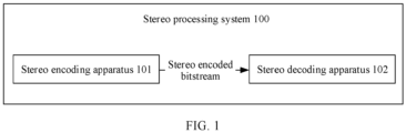
- FIG. 1 is a schematic diagram of a composition structure of a stereo processing system according to an embodiment of this application.
- the stereo processing system 100 may include a stereo encoding apparatus 101 and a stereo decoding apparatus 102.
- the stereo encoding apparatus 101 may be configured to generate a stereo encoded bitstream, and then the stereo encoded bitstream may be transmitted to the stereo decoding apparatus 102 through an audio transmission channel.
- the stereo decoding apparatus 102 may receive the stereo encoded bitstream, and then execute a stereo decoding function of the stereo decoding apparatus 102, to finally obtain a stereo decoded bitstream.
- the stereo encoding apparatus may be applied to various terminal devices that have an audio communication requirement, and a wireless device and a core network device that have a transcoding requirement.
- the stereo encoding apparatus may be a stereo encoder of the foregoing terminal device, wireless device, or core network device.
- the stereo decoding apparatus may be applied to various terminal devices that have an audio communication requirement, and a wireless device and a core network device that have a transcoding requirement.
- the stereo decoding apparatus may be a stereo decoder of the foregoing terminal device, wireless device, or core network device.
- FIG. 2a is a schematic diagram of application of a stereo encoder and a stereo decoder to a terminal device according to an embodiment of this application.
- Each terminal device may include a stereo encoder, a channel encoder, a stereo decoder, and a channel decoder.
- the channel encoder is used to perform channel encoding on a stereo signal
- the channel decoder is used to perform channel decoding on a stereo signal.
- a first terminal device 20 may include a first stereo encoder 201, a first channel encoder 202, a first stereo decoder 203, and a first channel decoder 204.
- a second terminal device 21 may include a second stereo decoder 211, a second channel decoder 212, a second stereo encoder 213, and a second channel encoder 214.
- the first terminal device 20 is connected to a wireless or wired first network communications device 22, the first network communications device 22 is connected to a wireless or wired second network communications device 23 through a digital channel, and the second terminal device 21 is connected to the wireless or wired second network communications device 23.
- the foregoing wireless or wired network communications device may generally refer to a signal transmission device, for example, a communications base station or a data exchange device.
- a terminal device serving as a transmit end performs stereo encoding on a collected stereo signal, then performs channel encoding, and transmits the stereo signal on a digital channel by using a wireless network or a core network.
- a terminal device serving as a receive end performs channel decoding based on a received signal to obtain a stereo signal encoded bitstream, and then restores a stereo signal through stereo decoding, and the terminal device serving as the receive end performs playback.
- FIG. 2b is a schematic diagram of application of a stereo encoder to a wireless device or a core network device according to an embodiment of this application.
- the wireless device or core network device 25 includes: a channel decoder 251, another audio decoder 252, a stereo encoder 253, and a channel encoder 254.
- the another audio decoder 252 is an audio decoder other than a stereo decoder.
- a signal entering the device is first channel-decoded by the channel decoder 251, then audio decoding (other than stereo decoding) is performed by the another audio decoder 252, and then stereo encoding is performed by using the stereo encoder 253.
- the stereo signal is channel-encoded by using the channel encoder 254, and then transmitted after the channel encoding is completed.
- FIG. 2c is a schematic diagram of application of a stereo decoder to a wireless device or a core network device according to an embodiment of this application.
- the wireless device or core network device 25 includes: a channel decoder 251, a stereo decoder 255, another audio encoder 256, and a channel encoder 254.
- the another audio encoder 256 is an audio encoder other than a stereo encoder.
- a signal entering the device is first channel-decoded by the channel decoder 251, then a received stereo encoded bitstream is decoded by using the stereo decoder 255, and then audio encoding (other than stereo encoding) is performed by using the another audio encoder 256.
- the stereo signal is channel-encoded by using the channel encoder 254, and then transmitted after the channel encoding is completed.
- a wireless device or a core network device if transcoding needs to be implemented, corresponding stereo encoding and decoding processing needs to be performed.
- the wireless device is a radio frequency-related device in communication
- the core network device is a core network-related device in communication.
- the stereo encoding apparatus may be applied to various terminal devices that have an audio communication requirement, and a wireless device and a core network device that have a transcoding requirement.
- the stereo encoding apparatus may be a multi-channel encoder of the foregoing terminal device, wireless device, or core network device.
- the stereo decoding apparatus may be applied to various terminal devices that have an audio communication requirement, and a wireless device and a core network device that have a transcoding requirement.
- the stereo decoding apparatus may be a multi-channel decoder of the foregoing terminal device, wireless device, or core network device.
- FIG. 3a is a schematic diagram of application of a multi-channel encoder and a multi-channel decoder to a terminal device according to an embodiment of this application.
- Each terminal device may include a multi-channel encoder, a channel encoder, a multi-channel decoder, and a channel decoder.
- the channel encoder is used to perform channel encoding on a multi-channel signal
- the channel decoder is used to perform channel decoding on a multi-channel signal.
- a first terminal device 30 may include a first multi-channel encoder 301, a first channel encoder 302, a first multi-channel decoder 303, and a first channel decoder 304.
- a second terminal device 31 may include a second multi-channel decoder 311, a second channel decoder 312, a second multi-channel encoder 313, and a second channel encoder 314.
- the first terminal device 30 is connected to a wireless or wired first network communications device 32
- the first network communications device 32 is connected to a wireless or wired second network communications device 33 through a digital channel
- the second terminal device 31 is connected to the wireless or wired second network communications device 33.
- the foregoing wireless or wired network communications device may generally refer to a signal transmission device, for example, a communications base station or a data exchange device.
- a terminal device serving as a transmit end performs multi-channel encoding on a collected multi-channel signal, then performs channel encoding, and transmits the multi-channel signal on a digital channel by using a wireless network or a core network.
- a terminal device serving as a receive end performs channel decoding based on a received signal to obtain a multi-channel signal encoded bitstream, and then restores a multi-channel signal through multi-channel decoding, and the terminal device serving as the receive end performs playback.
- FIG. 3b is a schematic diagram of application of a multi-channel encoder to a wireless device or a core network device according to an embodiment of this application.
- the wireless device or core network device 35 includes: a channel decoder 351, another audio decoder 352, a multi-channel encoder 353, and a channel encoder 354.
- FIG. 3b is similar to FIG. 2b , and details are not described herein again.
- FIG. 3c is a schematic diagram of application of a multi-channel decoder to a wireless device or a core network device according to an embodiment of this application.
- the wireless device or core network device 35 includes: a channel decoder 351, a multi-channel decoder 355, another audio encoder 356, and a channel encoder 354.
- FIG. 3c is similar to FIG. 2c , and details are not described herein again.
- Stereo encoding processing may be a part of a multi-channel encoder, and stereo decoding processing may be a part of a multi-channel decoder.
- performing multi-channel encoding on a collected multi-channel signal may be performing dimension reduction processing on the collected multi-channel signal to obtain a stereo signal, and encoding the obtained stereo signal.
- a decoder side performs decoding based on a multi-channel signal encoded bitstream, to obtain a stereo signal, and restores a multi-channel signal after upmix processing. Therefore, the embodiments of this application may also be applied to a multi-channel encoder and a multi-channel decoder in a terminal device, a wireless device, or a core network device. In a wireless device or a core network device, if transcoding needs to be implemented, corresponding multi-channel encoding and decoding processing needs to be performed.
- pitch period encoding is an important step in the stereo encoding method. Because voiced sound is generated through quasi-periodic impulse excitation, a time-domain waveform of the voiced sound shows obvious periodicity, which is called pitch period.
- a pitch period plays an important role in producing high-quality voiced speech because voiced speech is characterized as a quasi-periodic signal composed of sampling points separated by a pitch period.
- a pitch period may also be represented by a quantity of samples included in a period. In this case, the pitch period is called pitch delay.
- a pitch delay is an important parameter of an adaptive codebook.
- Pitch period estimation mainly refers to a process of estimating a pitch period. Therefore, accuracy of pitch period estimation directly determines correctness of an excitation signal, and accordingly determines synthesized speech signal quality.
- a small quantity of bit resources are used to indicate a pitch period at medium and low bit rates, which is one of the reasons for quality deterioration of speech encoding.
- Pitch periods of a primary channel signal and a secondary channel signal are very similar. In the embodiments of this application, the similarity of the pitch periods can be properly used to improve encoding efficiency.
- the accuracy of pitch period estimation is an important factor affecting overall stereo encoding quality at medium and low rates.
- the pitch period parameter of the secondary channel signal is reasonably predicted and differential-encoded by using a differential encoding method. In this way, only a small quantity of bit resources are required to be allocated for quantization and encoding of the pitch period of the secondary channel signal.
- the embodiments of this application can improve a sense of space and sound image stability of stereo signals.
- bit resources are used for the pitch period of the secondary channel signal, so that accuracy of pitch period prediction for the secondary channel signal is ensured.
- the remaining bit resources are used for other stereo encoding parameters, for example, a fixed codebook. Therefore, encoding efficiency of the secondary channel is improved, and overall stereo encoding quality is finally improved.
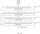
- FIG. 4 is a schematic flowchart of interaction between a stereo encoding apparatus and a stereo decoding apparatus according to an embodiment of this application.
- the following step 401 to step 403 may be performed by the stereo encoding apparatus (briefly referred to as an encoder side below).
- the following step 411 to step 413 may be performed by the stereo decoding apparatus (briefly referred to as a decoder side below).
- the interaction mainly includes the following process.
- the current frame is a stereo signal frame on which encoding processing is currently performed on the encoder side.
- the left channel signal of the current frame and the right channel signal of the current frame are first obtained, and downmix processing is performed on the left channel signal and the right channel signal, to obtain the primary channel signal of the current frame and the secondary channel signal of the current frame.
- the encoder side downmixes time-domain signals into two mono signals.
- Left and right channel signals are first downmixed into a primary channel signal and a secondary channel signal, where L represents the left channel signal, and R represents the right channel signal.
- the primary channel signal may be 0.5 * (L + R), which indicates information about a correlation between the two channels
- the secondary channel signal may be 0.5 * (L - R), which indicates information about a difference between the two channels.
- the stereo encoding method executed by the encoder side may be applied to a stereo encoding scenario in which an encoding rate of a current frame is lower than a preset rate threshold.
- the stereo decoding method executed by the decoder side may be applied to a stereo decoding scenario in which a decoding rate of a current frame is lower than a preset rate threshold.
- the encoding rate of the current frame is an encoding rate used by a stereo signal of the current frame, and the rate threshold is a minimum rate value specified for the stereo signal.
- the stereo encoding method provided in this embodiment of this application may be performed.
- the stereo decoding method provided in this embodiment of this application may be performed.
- the rate threshold is at least one of the following values: 13.2 kilobits per second kbps, 16.4 kbps, or 24.4 kbps.
- the rate threshold may be less than or equal to 13.2 kbps.
- the rate threshold may alternatively be 16.4 kbps or 24.4 kbps.
- a specific value of the rate threshold may be determined based on an application scenario.
- the encoding rate is relatively low (for example, 24.4 kbps or lower)
- independent encoding is not performed on the pitch period of the secondary channel, and an estimated pitch period value of the primary channel signal is used as a reference value.
- the differential encoding method is used to implement encoding of the pitch period of the secondary channel signal, to improve stereo encoding quality.
- the primary channel signal of the current frame and the secondary channel signal of the current frame may be obtained, it may be determined, based on the primary channel signal and the secondary channel signal of the current frame, whether differential encoding can be performed on the pitch period of the secondary channel signal. For example, whether to perform differential encoding on the pitch period of the secondary channel signal is determined based on signal characteristics of the primary channel signal and the secondary channel signal of the current frame. For another example, the primary channel signal, the secondary channel signal, and a preset decision condition may be used to determine whether to perform differential encoding on the pitch period of the secondary channel signal. There are a lot of manners of using the primary channel signal and the secondary channel signal to determine whether to perform differential encoding, which are separately described in detail in subsequent embodiments.
- step 402 of determining whether to perform differential encoding on the pitch period of the secondary channel signal includes:
- encoding may be performed based on the primary channel signal, to obtain the estimated pitch period value of the primary channel signal.
- pitch period estimation is performed through a combination of open-loop pitch analysis and closed-loop pitch search, so as to improve accuracy of pitch period estimation.
- a pitch period of a speech signal may be estimated by using a plurality of methods, for example, using an autocorrelation function, or using a short-term average amplitude difference.
- a pitch period estimation algorithm is based on the autocorrelation function.
- the autocorrelation function has a peak at an integer multiple of a pitch period, and this feature can be used to estimate the pitch period.
- pitch period estimation includes two steps: open-loop pitch analysis and closed-loop pitch search.
- Open-loop pitch analysis is used to roughly estimate an integer delay of a frame of speech to obtain a candidate integer delay.
- Closed-loop pitch search is used to finely estimate a pitch delay in the vicinity of the integer delay, and closed-loop pitch search is performed once per subframe.
- Open-loop pitch analysis is performed once per frame, to compute autocorrelation, normalization, and an optimum open-loop integer delay.
- the estimated pitch period value of the primary channel signal may be obtained by using the foregoing process.
- open-loop pitch period analysis may be performed on the secondary channel signal, to obtain the estimated open-loop pitch period value of the secondary channel signal.
- a specific process of the open-loop pitch period analysis is not described in detail.
- the difference between the estimated pitch period value of the primary channel signal and the estimated open-loop pitch period value of the secondary channel signal may be calculated, and then it is determined whether the difference exceeds the preset secondary channel pitch period differential encoding threshold.
- the secondary channel pitch period differential encoding threshold may be preset, and may be flexibly configured with reference to a stereo encoding scenario. When the difference exceeds the secondary channel pitch period differential encoding threshold, it is determined to perform differential encoding, or when the difference does not exceed the secondary channel pitch period differential encoding threshold, it is determined not to perform differential encoding.
- a manner of determining whether to perform differential encoding on the pitch period of the secondary channel signal is not limited to the foregoing determining through comparison of the difference and the secondary channel pitch period differential encoding threshold. For example, it may be alternatively determined based on whether a result of dividing the difference by the secondary channel pitch period differential encoding threshold is less than 1.
- the estimated pitch period value of the primary channel signal may be divided by the estimated open-loop pitch period value of the secondary channel signal, and a value of the obtained division result is compared with the secondary channel pitch period differential encoding threshold.
- a specific value of the secondary channel pitch period differential encoding threshold may be determined with reference to an application scenario. This is not limited herein.
- a pitch period differential encoding decision of the secondary channel is performed based on the estimated pitch period value of the primary channel signal and the estimated open-loop pitch period value of the secondary channel signal.
- DIFF represents the difference between the estimated pitch period value of the primary channel signal and the estimated open-loop pitch period value of the secondary channel signal.
- represents an absolute value of the difference between ⁇ (pitch[0]) and ⁇ (pitch[1]).
- ⁇ (pitch[0]) represents the estimated pitch period value of the primary channel signal, and ⁇ (pitch[1]) represents the estimated open-loop pitch period value of the secondary channel signal.
- the decision condition that can be used in this embodiment of this application may not be limited to the foregoing formula.
- a correction factor may be further set, and a result of multiplying
- step 403 is determined based on a result of the foregoing determining.
- the subsequent step 403 is triggered to be performed.
- the method provided in this embodiment of this application further includes: when determining to perform differential encoding on the pitch period of the secondary channel signal, configuring a secondary channel pitch period differential encoding flag in the current frame to a preset first value, where a stereo encoded bitstream carries the secondary channel pitch period differential encoding flag, and the first value is used to indicate to perform differential encoding on the pitch period of the secondary channel signal.
- the encoder side obtains the secondary channel pitch period differential encoding flag.
- a value of the secondary channel pitch period differential encoding flag may be configured based on whether to perform differential encoding on the pitch period of the secondary channel signal.
- the secondary channel pitch period differential encoding flag is used to indicate whether to perform differential encoding on the pitch period of the secondary channel signal.
- the secondary channel pitch period differential encoding flag may have a plurality of values.
- the secondary channel pitch period differential encoding flag may be the preset first value or a second value.
- the following describes an example of a method for configuring the secondary channel pitch period differential encoding flag.
- the secondary channel pitch period differential encoding flag is configured to the first value.
- the decoder side can determine that differential decoding may be performed on the pitch period of the secondary channel signal.
- the value of the secondary channel pitch period differential encoding flag may be 0 or 1, where the first value is 1, and the second value is 0.
- the secondary channel pitch period differential encoding flag is indicated by Pitch_reuse _flag.
- the method provided in this embodiment of this application further includes: when determining to skip performing differential encoding on the pitch period of the secondary channel signal and skip reusing the estimated pitch period value of the primary channel signal as the pitch period of the secondary channel signal, separately encoding the pitch period of the secondary channel signal and a pitch period of the primary channel signal.
- a pitch period independent encoding method for the secondary channel may be used in this embodiment of this application, to encode the pitch period of the secondary channel signal, so that the pitch period of the secondary channel signal can be encoded.
- the method provided in this embodiment of this application further includes: when determining to skip performing differential encoding on the pitch period of the secondary channel signal and reuse the estimated pitch period value of the primary channel signal as the pitch period of the secondary channel signal, configuring a secondary channel signal pitch period reuse flag to a preset fourth value, and using the stereo encoded bitstream to carry the secondary channel signal pitch period reuse flag, where the fourth value is used to indicate to reuse the estimated pitch period value of the primary channel signal as the pitch period of the secondary channel signal.
- a pitch period reusing method may be used in this embodiment of this application.
- the encoder side does not encode the pitch period of the secondary channel, and the stereo encoded bitstream carries the secondary channel signal pitch period reuse flag.
- the secondary channel signal pitch period reuse flag is used to indicate whether the pitch period of the secondary channel signal reuses the estimated pitch period value of the primary channel signal.
- the decoder side may use, based on the secondary channel signal pitch period reuse flag, the pitch period of the primary channel signal as the pitch period of the secondary channel signal for decoding.
- the method provided in this embodiment of this application further includes:
- the secondary channel pitch period differential encoding flag may have a plurality of values.
- the secondary channel pitch period differential encoding flag may be the preset first value or the second value.
- the following describes an example of a method for configuring the secondary channel pitch period differential encoding flag.
- the secondary channel pitch period differential encoding flag is configured to the second value.
- the decoder side can determine that differential decoding may not be performed on the pitch period of the secondary channel signal.
- a value of the secondary channel pitch period differential encoding flag may be 0 or 1, the first value is 1, and the second value is 0. Based on the fact that the secondary channel pitch period differential encoding flag indicates the second value, the decoder side can determine not to perform differential decoding on the pitch period of the secondary channel signal.
- the secondary channel pitch period reuse flag may have a plurality of values.
- the secondary channel pitch period reuse flag may be the preset fourth value or the third value.
- the following describes an example of a method for configuring the secondary channel pitch period reuse flag.
- the secondary channel pitch period reuse flag is configured to the third value.
- the decoder side can determine not to reuse the estimated pitch period value of the primary channel signal as the pitch period of the secondary channel signal.
- a value of the secondary channel pitch period reuse flag may be 0 or 1, the fourth value is 1, and the third value is 0.
- the encoder side may use an independent encoding method, that is, separately encode the pitch period of the secondary channel signal and the pitch period of the primary channel signal.
- the pitch period independent encoding method for the secondary channel may be used to encode the pitch period of the secondary channel signal.
- a pitch period reusing method may be alternatively used.
- the stereo encoding method executed by the encoder side may be applied to a stereo encoding scenario in which an encoding rate of the current frame is lower than a preset rate threshold. If differential encoding is not performed by using the pitch period of the secondary channel signal, the secondary channel pitch period reusing method may be used.
- the secondary channel pitch period is not encoded on the encoder side, and the stereo encoded bitstream carries the secondary channel signal pitch period reuse flag.
- the secondary channel signal pitch period reuse flag is used to indicate whether the pitch period of the secondary channel signal reuses the estimated pitch period value of the primary channel signal, and when the secondary channel signal pitch period reuse flag indicates that the pitch period of the secondary channel signal reuses the estimated pitch value period of the primary channel signal, the decoder side may use, based on the secondary channel signal pitch period reuse flag, the pitch period of the primary channel signal as the pitch period of the secondary channel signal for decoding.
- the method provided in this embodiment of this application further includes:
- the secondary channel pitch period differential encoding flag may have a plurality of values.
- the secondary channel pitch period differential encoding flag may be the preset first value or the second value.
- the following describes an example of a method for configuring the secondary channel pitch period differential encoding flag.
- the secondary channel pitch period differential encoding flag is configured to the second value.
- the decoder side can determine that differential decoding may not be performed on the pitch period of the secondary channel signal.
- a value of the secondary channel pitch period differential encoding flag may be 0 or 1, the first value is 1, and the second value is 0. Based on the fact that the secondary channel pitch period differential encoding flag indicates the second value, the decoder side can determine not to perform differential decoding on the pitch period of the secondary channel signal.
- the secondary channel pitch period reuse flag may have a plurality of values.
- the secondary channel pitch period reuse flag may be the preset fourth value or the third value.
- the encoder side determines to skip performing differential encoding on the pitch period of the secondary channel signal and reuse the estimated pitch period value of the primary channel signal as the pitch period of the secondary channel signal
- the value of the secondary channel signal pitch period reuse flag is configured to the fourth value.
- the following describes an example of a method for configuring the secondary channel pitch period reuse flag.
- the secondary channel pitch period reuse flag is configured to the fourth value.
- the decoder side can determine to reuse the estimated pitch period value of the primary channel signal as the pitch period of the secondary channel signal.
- a value of the secondary channel pitch period reuse flag may be 0 or 1, the fourth value is 1, and the third value is 0.
- differential encoding may be performed on the pitch period of the secondary channel signal by using the estimated pitch period value of the primary channel signal. Because the estimated pitch period value of the primary channel signal is used in the differential encoding, an estimated pitch period value of the secondary channel signal is accurately encoded through differential encoding in consideration of pitch period similarity between the primary channel signal and the secondary channel signal. The secondary channel signal can be more accurately decoded by using the estimated pitch period value of the secondary channel signal, so that a sense of space and sound image stability of the stereo signal can be improved.
- differential encoding is performed on the pitch period of the secondary channel signal in this embodiment of this application, so that bit resource overheads used for independently encoding the pitch period of the secondary channel signal can be reduced, and saved bits can be allocated to other stereo encoding parameters, to implement accurate secondary channel pitch period encoding and improve overall stereo encoding quality.
- encoding is performed based on the primary channel signal, to obtain the estimated pitch period value of the primary channel signal.
- pitch period estimation is performed through a combination of open-loop pitch analysis and closed-loop pitch search, so as to improve accuracy of pitch period estimation.
- a pitch period of a speech signal may be estimated by using a plurality of methods, for example, using an autocorrelation function, or using a short-term average amplitude difference.
- a pitch period estimation algorithm is based on the autocorrelation function.
- the autocorrelation function has a peak at an integer multiple of a pitch period, and this feature can be used to estimate the pitch period.
- pitch period estimation includes two steps: open-loop pitch analysis and closed-loop pitch search.
- Open-loop pitch analysis is used to roughly estimate an integer delay of a frame of speech to obtain a candidate integer delay.
- Closed-loop pitch search is used to finely estimate a pitch delay in the vicinity of the integer delay, and closed-loop pitch search is performed once per subframe.
- Open-loop pitch analysis is performed once per frame, to compute autocorrelation, normalization, and an optimum open-loop integer delay.
- the estimated pitch period value of the primary channel signal may be obtained by using the foregoing process.
- step 403 of performing differential encoding on the pitch period of the secondary channel signal by using the estimated pitch period value of the primary channel signal, to obtain a pitch period index value of the secondary channel signal includes:
- the encoder side first performs secondary channel signal closed-loop pitch period search based on the estimated pitch period value of the secondary channel signal, to determine the estimated pitch period value of the secondary channel signal.
- the following describes a specific process of closed-loop pitch period search in detail.
- the performing secondary channel signal closed-loop pitch period search based on the estimated pitch period value of the primary channel signal, to obtain the estimated pitch period value of the secondary channel signal includes:
- the quantity of subframes into which the secondary channel signal of the current frame is divided may be determined based on a subframe configuration of the secondary channel signal.
- the secondary channel signal may be divided into four subframes or three subframes, which is specifically determined with reference to an application scenario.
- the estimated pitch period value of the primary channel signal is obtained, the estimated pitch period value of the primary channel signal and the quantity of subframes into which the secondary channel signal is divided may be used to calculate the closed-loop pitch period reference value of the secondary channel signal.
- the closed-loop pitch period reference value of the secondary channel signal is a reference value determined based on the estimated pitch period value of the primary channel signal.
- the closed-loop pitch period reference value of the secondary channel signal represents a closed-loop pitch period of the secondary channel signal that is determined by using the estimated pitch period value of the primary channel signal as a reference.
- one method is to directly use a pitch period of the primary channel signal as the closed-loop pitch period reference value of the secondary channel signal. That is, four values are selected from pitch periods of five subframes of the primary channel signal as closed-loop pitch period reference values of four subframes of the secondary channel signal.
- the pitch periods of the five subframes of the primary channel signal are mapped to closed-loop pitch period reference values of the four subframes of the secondary channel signal by using an interpolation method.
- closed-loop pitch period search is performed by using integer precision and downsampling fractional precision and by using the closed-loop pitch period reference value of the secondary channel signal as the start point of the secondary channel signal closed-loop pitch period search, and finally an interpolated normalized correlation is computed to obtain the estimated pitch period value of the secondary channel signal.
- an interpolated normalized correlation is computed to obtain the estimated pitch period value of the secondary channel signal.
- the pitch period search range adjustment factor of the secondary channel signal may be used to adjust the pitch period index value of the secondary channel signal, to determine the upper limit of the pitch period index value of the secondary channel signal.
- the upper limit of the pitch period index value of the secondary channel signal indicates an upper limit value that the pitch period index value of the secondary channel signal cannot exceed.
- the determining a closed-loop pitch period reference value of the secondary channel signal based on the estimated pitch period value of the primary channel signal and a quantity of subframes into which the secondary channel signal of the current frame is divided includes:
- the closed-loop pitch period integer part and the closed-loop pitch period fractional part of the secondary channel signal are first determined based on the estimated pitch period value of the primary channel signal.
- an integer part of the estimated pitch period value of the primary channel signal is directly used as the closed-loop pitch period integer part of the secondary channel signal, and a fractional part of the estimated pitch period value of the primary channel signal is used as the closed-loop pitch period fractional part of the secondary channel signal.
- the estimated pitch period value of the primary channel signal may be mapped to the closed-loop pitch period integer part and the closed-loop pitch period fractional part of the secondary channel signal by using an interpolation method.
- the closed-loop pitch period integer part loc_T0 and the closed-loop pitch period fractional part loc _frac_prim of the secondary channel may be obtained.
- N represents the quantity of subframes into which the secondary channel signal is divided.
- a value of N may be 3, 4, 5, or the like.
- a specific value depends on an application scenario.
- the closed-loop pitch period reference value of the secondary channel signal may be calculated by using the foregoing formula. In this embodiment of this application, the calculation of the closed-loop pitch period reference value of the secondary channel signal may not be limited to the foregoing formula. For example, after a result of loc_T0 + loc_frac_prim/N is obtained, a correction factor may further be set.
- a result of multiplying the correction factor by loc_T0 + loc_frac_prim/N may be used as the final output f_pitch_prim.
- N on the right side of the equation f_pitch_prim loc_T0 + loc_frac_prim/N may be replaced with N-1, and the final f_pitch_prim may also be calculated.
- the determining an upper limit of the pitch period index value of the secondary channel signal based on a pitch period search range adjustment factor of the secondary channel signal includes:
- Z may be 3, 4, or 5, and a specific value of Z is not limited herein, depending on an application scenario.
- the encoder side After determining the estimated pitch period value of the primary channel signal, the estimated pitch period value of the secondary channel signal, and the upper limit of the pitch period index value of the secondary channel signal, the encoder side performs differential encoding based on the estimated pitch period value of the primary channel signal, the estimated pitch period value of the secondary channel signal, and the upper limit of the pitch period index value of the secondary channel signal, and outputs the pitch period index value of the secondary channel signal.
- the calculating the pitch period index value of the secondary channel signal based on the estimated pitch period value of the primary channel signal, the estimated pitch period value of the secondary channel signal, and the upper limit of the pitch period index value of the secondary channel signal includes:
- the closed-loop pitch period integer part loc_T0 of the secondary channel signal and the closed-loop pitch period fractional part loc _frac_prim of the secondary channel signal are first determined based on the estimated pitch period value of the primary channel signal.
- N represents the quantity of subframes into which the secondary channel signal is divided, for example, a value of N may be 3, 4, or 5.
- M represents the adjustment factor of the upper limit of the pitch period index value of the secondary channel signal, and M is a non-zero real number, for example, a value of M may be 2 or 3. Values of N and M depend on an application scenario, and are not limited herein.
- calculation of the pitch period index value of the secondary channel signal may not be limited to the foregoing formula.
- a correction factor may be further set, and a result obtained by multiplying the correction factor by (N * pitch_soft_reuse + pitch_frac_soft_reuse) - (N * loc_T0 + loc_frac_prim) + soft_reuse_index_high_limit/M may be used as a final output soft_reuse_index.
- a specific value of the correction factor is not limited, and a final soft_reuse_index may also be calculated.
- the stereo encoded bitstream generated by the encoder side may be stored in a computer-readable storage medium.
- differential encoding is performed on the pitch period of the secondary channel signal by using the estimated pitch period value of the primary channel signal, to obtain the pitch period index value of the secondary channel signal.
- the pitch period index value of the secondary channel signal is used to indicate the pitch period of the secondary channel signal.
- the pitch period index value of the secondary channel signal may be further used to generate the to-be-sent stereo encoded bitstream.
- the encoder side may output the stereo encoded bitstream, and send the stereo encoded bitstream to the decoder side through an audio transmission channel. 411: Determine, based on the received stereo encoded bitstream, whether to perform differential decoding on the pitch period of the secondary channel signal.
- the decoder side may determine, based on indication information carried in the stereo encoded bitstream, whether to perform differential decoding on the pitch period of the secondary channel signal. For another example, after a transmission environment of the stereo signal is preconfigured, whether to perform differential decoding may be preconfigured. In this case, the decoder side may further determine, based on a result of the preconfiguration, whether to perform differential decoding on the pitch period of the secondary channel signal.
- step 411 of determining, based on the received stereo encoded bitstream, whether to perform differential decoding on the pitch period of the secondary channel signal includes:
- the secondary channel pitch period differential encoding flag may have a plurality of values.
- the secondary channel pitch period differential encoding flag may be the preset first value or the second value.
- the value of the secondary channel pitch period differential encoding flag may be 0 or 1, where the first value is 1, and the second value is 0.
- step 412 is triggered.
- the secondary channel pitch period differential encoding flag is Pitch_reuse_flag.
- the secondary channel pitch period differential encoding flag Pitch_reuse _flag is obtained.
- Pitch_reuse_flag is 1, and the differential decoding method in this embodiment of this application is performed.
- Pitch_reuse_flag is 0, and an independent decoding method is performed.
- the differential decoding process in step 412 and step 413 is performed only when Pitch _reuse _flag is 1.
- the method provided in this embodiment of this application further includes: when determining to skip performing differential decoding on the pitch period of the secondary channel signal and skip reusing the estimated pitch period value of the primary channel signal as the pitch period of the secondary channel signal, decoding the pitch period of the secondary channel signal from the stereo encoded bitstream.
- a pitch period independent decoding method for the secondary channel may be used in this embodiment of this application, to decode the pitch period of the secondary channel signal, so that the pitch period of the secondary channel signal can be decoded.
- the method provided in this embodiment of this application further includes: when determining to skip performing differential decoding on the pitch period of the secondary channel signal and reuse the estimated pitch period value of the primary channel signal as the pitch period of the secondary channel signal, using the estimated pitch period value of the primary channel signal as the pitch period of the secondary channel signal.
- a pitch period reusing method may be used in this embodiment of this application. For example, when the secondary channel signal pitch period reuse flag indicates that the pitch period of the secondary channel signal reuses the estimated pitch period value of the primary channel signal, the decoder side may perform decoding based on the secondary channel signal pitch period reuse flag by using the pitch period of the primary channel signal as the pitch period of the secondary channel signal.
- the stereo decoding method performed by the decoder side may further include the following steps: when the secondary channel pitch period differential encoding flag is the preset second value, and the secondary channel signal pitch period reuse flag carried in the stereo encoded bitstream is the preset third value, determining not to perform differential decoding on the pitch period of the secondary channel signal, and not to reuse the estimated pitch period value of the primary channel signal as the pitch period of the secondary channel signal, and decoding the pitch period of the secondary channel signal from the stereo encoded bitstream.
- the stereo decoding method performed by the decoder side may further include the following steps: when the secondary channel pitch period differential encoding flag is the preset second value, and the secondary channel signal pitch period reuse flag carried in the stereo encoded bitstream is the preset fourth value, determining not to perform differential decoding on the pitch period of the secondary channel signal, and using the estimated pitch period value of the primary channel signal as the pitch period of the secondary channel signal.
- the secondary channel pitch period differential encoding flag is the second value, it is determined not to perform the differential decoding process in step 412 and step 413, and the secondary channel signal pitch period reuse flag carried in the stereo encoded bitstream is further parsed.
- the secondary channel signal pitch period reuse flag is used to indicate whether the pitch period of the secondary channel signal reuses the estimated pitch period value of the primary channel signal.
- the value of the secondary channel signal pitch period reuse flag is the fourth value, it indicates that the pitch period of the secondary channel signal reuses the estimated pitch period value of the primary channel signal, and the decoder side may perform decoding based on the secondary channel signal pitch period reuse flag by using the pitch period of the primary channel signal as the pitch period of the secondary channel signal.
- the value of the secondary channel signal pitch period reuse flag is the third value, it indicates that the pitch period of the secondary channel signal does not reuse the estimated pitch period value of the primary channel signal, and the decoder side decodes the pitch period of the secondary channel signal from the stereo encoded bitstream.
- the pitch period of the secondary channel signal and the pitch period of the primary channel signal may be decoded separately, that is, the pitch period of the secondary channel signal is decoded independently.
- the decoder side may determine, based on the secondary channel pitch period differential encoding flag carried in the stereo encoded bitstream, to execute the differential decoding method or the independent decoding method.
- the pitch period independent decoding method for the secondary channel may be used to decode the pitch period of the secondary channel signal.
- a pitch period reusing method may be alternatively used.
- the stereo decoding method executed by the decoder side may be applied to a stereo decoding scenario in which a decoding rate of the current frame is lower than a preset rate threshold. If the stereo encoded bitstream carries the secondary channel signal pitch period reuse flag, the secondary channel signal pitch period reuse flag is used to indicate whether the pitch period of the secondary channel signal reuses the estimated pitch period value of the primary channel signal.
- the decoder side may use, based on the secondary channel signal pitch period reuse flag, the pitch period of the primary channel signal as the pitch period of the secondary channel signal for decoding.
- the decoder side after the encoder side sends the stereo encoded bitstream, the decoder side first receives the stereo encoded bitstream through the audio transmission channel, and then performs channel decoding based on the stereo encoded bitstream. If differential decoding needs to be performed on the pitch period of the secondary channel signal, the pitch period index value of the secondary channel signal of the current frame may be obtained from the stereo encoded bitstream, and the estimated pitch period value of the primary channel signal of the current frame may be obtained from the stereo encoded bitstream.
- the estimated pitch period value of the primary channel signal and the pitch period index value of the secondary channel signal may be used to perform differential decoding on the pitch period of the secondary channel signal, to accurately decode the pitch period of the secondary channel and improve overall stereo decoding quality.
- step 413 of performing differential decoding on the pitch period of the secondary channel signal based on the estimated pitch period value of the primary channel signal and the pitch period index value of the secondary channel signal includes:
- the closed-loop pitch period reference value of the secondary channel signal is determined by using the estimated pitch period value of the primary channel signal. For details, refer to the foregoing calculation process.
- the pitch period search range adjustment factor of the secondary channel signal may be used to adjust the pitch period index value of the secondary channel signal, to determine the upper limit of the pitch period index value of the secondary channel signal.
- the upper limit of the pitch period index value of the secondary channel signal indicates an upper limit value that the pitch period index value of the secondary channel signal cannot exceed.
- the pitch period index value of the secondary channel signal may be used to determine the pitch period index value of the secondary channel signal.
- the decoder side After determining the closed-loop pitch period reference value of the secondary channel signal, the pitch period index value of the secondary channel signal, and the upper limit of the pitch period index value of the secondary channel signal, the decoder side performs differential decoding based on the closed-loop pitch period reference value of the secondary channel signal, the pitch period index value of the secondary channel signal, and the upper limit of the pitch period index value of the secondary channel signal, and outputs the estimated pitch period value of the secondary channel signal.
- the calculating the estimated pitch period value of the secondary channel signal based on the closed-loop pitch period reference value of the secondary channel signal, the pitch period index value of the secondary channel signal, and the upper limit of the pitch period index value of the secondary channel signal includes:
- the closed-loop pitch period integer part loc_T0 of the secondary channel signal and the closed-loop pitch period fractional part loc _frac_prim of the secondary channel signal are first determined based on the estimated pitch period value of the primary channel signal.
- N represents the quantity of subframes into which the secondary channel signal is divided, for example, a value of N may be 3, 4, or 5.
- M represents the adjustment factor of the upper limit of the pitch period index value of the secondary channel signal, for example, a value of M may be 2 or 3. Values of N and M depend on an application scenario, and are not limited herein.
- calculation of the estimated pitch period value of the secondary channel signal may not be limited to the foregoing formula.
- a correction factor may be further set, and a result obtained by multiplying the correction factor by f_pitch_prim + (soft_reuse_index - soft_reuse_index_high_limit/M)/N may be used as the final output T0_pitch.
- an integer part T0 of the estimated pitch period value and a fractional part T0_frac of the estimated pitch period value of the secondary channel signal may be further calculated based on the estimated pitch period value T0_pitch of the secondary channel signal.
- T0 INT(T0_pitch)
- T0_frac (T0_pitch - T0) * N.
- T0_pitch indicates to round down T0_pitch to the nearest integer
- T0 indicates to decode the integer part of the estimated pitch period value of the secondary channel
- T0_frac indicates to decode the fractional part of the estimated pitch period value of the secondary channel.
- the estimated pitch period value of the primary channel signal and the pitch period index value of the secondary channel signal may be used to perform differential decoding on the pitch period of the secondary channel signal, to obtain the estimated pitch period value of the secondary channel signal, and the stereo encoded bitstream may be decoded by using the estimated pitch period value of the secondary channel signal. Therefore, a sense of space and sound image stability of the stereo signal can be improved.
- the pitch period encoding solution for the secondary channel signal proposed in this embodiment of this application, in a pitch period encoding process of the secondary channel signal, whether differential encoding can be performed on the pitch period of the secondary channel signal is determined, and when differential encoding can be performed on the pitch period of the secondary channel signal, a differential encoding method oriented to the pitch period of the secondary channel signal is used to encode the pitch period of the secondary channel signal.
- a small quantity of bit resources are used for differential encoding, and saved bits are allocated to other stereo encoding parameters to achieve accurate pitch period encoding for the secondary channel signal and improve the overall stereo encoding quality.
- the stereo signal may be an original stereo signal, or a stereo signal formed by two channels of signals included in a multi-channel signal, or a stereo signal formed by two channels of signals that are jointly generated by a plurality of channels of signals included in a multi-channel signal.
- the stereo encoding apparatus may constitute an independent stereo encoder, or may be used in a core encoding part in a multi-channel encoder, to encode a stereo signal including two channels of signals jointly generated by a plurality of channels of signals included in a multi-channel signal.
- FIG. 5A and FIG. 5B are a schematic flowchart of stereo signal encoding according to an embodiment of this application.
- This embodiment of this application provides a pitch period encoding determining method in stereo coding.
- the stereo coding may be time-domain stereo coding, or may be frequency-domain stereo coding, or may be time-frequency combined stereo coding. This is not limited in this embodiment of this application.
- frequency-domain stereo coding as an example, the following describes an encoding/decoding process of stereo coding, and focuses on an encoding process of a pitch period in secondary channel signal coding in subsequent steps.
- an encoder side of frequency-domain stereo coding is described. Specific implementation steps of the encoder side are as follows: S01: Perform time-domain preprocessing on left and right channel time-domain signals.
- a stereo signal of a current frame includes a left channel time-domain signal of the current frame and a right channel time-domain signal of the current frame.
- the left channel time-domain signal of the current frame is denoted as x L ( n )
- the left and right channel time-domain signals of the current frame are short for the left channel time-domain signal of the current frame and the right channel time-domain signal of the current frame.
- the performing time-domain preprocessing on left and right channel time-domain signals of the current frame may include: performing high-pass filtering on the left and right channel time-domain signals of the current frame to obtain preprocessed left and right channel time-domain signals of the current frame.
- the preprocessed left channel time-domain signal of the current frame is denoted as x L_HP ( n )
- the preprocessed right channel time-domain signal of the current frame is denoted as X R _ HP ( n ) .
- n is a sampling point number
- n 0,1, ⁇ , N -1.
- the preprocessed left and right channel time-domain signals of the current frame are short for the preprocessed left channel time-domain signal of the current frame and the preprocessed right channel time-domain signal of the current frame.
- High-pass filtering may be performed by an infinite impulse response (infinite impulse response, IIR) filter whose cut-off frequency is 20 Hz, or may be performed by a filter of another type.
- IIR infinite impulse response
- left and right channel signals used for delay estimation are left and right channel signals in the original stereo signal.
- the left and right channel signals in the original stereo signal refer to a pulse code modulation (pulse code modulation, PCM) signal obtained after analog-to-digital conversion.
- a sampling rate of the signal may include 8 KHz, 16 KHz, 32 KHz, 44.1 KHz, and 48 KHz.
- the preprocessing may further include other processing, for example, pre-emphasis processing. This is not limited in this embodiment of this application.
- S02 Perform time-domain analysis based on the preprocessed left and right channel signals.
- the time-domain analysis may include transient detection and the like.
- the transient detection may be separately performing energy detection on the preprocessed left and right channel time-domain signals of the current frame, for example, detecting whether a sudden energy change occurs in the current frame. For example, energy E cur _ L of the preprocessed left channel time-domain signal of the current frame is calculated, and transient detection is performed based on an absolute value of a difference between energy E pre _L of a preprocessed left channel time-domain signal of a previous frame and the energy E cur_ L of the preprocessed left channel time-domain signal of the current frame, to obtain a transient detection result of the preprocessed left channel time-domain signal of the current frame.
- the time-domain analysis may include other time-domain analysis in addition to transient detection, for example, may include determining a time-domain inter-channel time difference (inter-channel time difference, ITD) parameter, delay alignment processing in time domain, and frequency band extension preprocessing.
- ITD inter-channel time difference
- S03 Perform time-frequency transform on the preprocessed left and right channel signals, to obtain left and right channel frequency-domain signals.
- discrete Fourier transform may be performed on the preprocessed left channel signal to obtain the left channel frequency-domain signal
- discrete Fourier transform may be performed on the preprocessed right channel signal to obtain the right channel frequency-domain signal.
- an overlap-add method may be used for processing between two consecutive times of discrete Fourier transform, and sometimes, zero may be added to an input signal of discrete Fourier transform.
- L i (k) a transformed left channel frequency-domain signal of the i th subframe
- R i (k) a transformed right channel frequency-domain signal of the i th subframe
- the wideband means that an encoding bandwidth may be 8 KHz or greater, each frame of left channel signal or each frame of right channel signal is 20 ms, and a frame length is denoted as N.
- N 320, that is, the frame length is 320 sampling points.
- Each subframe of signal is 10 ms, and a subframe length is 160 sampling points.
- Discrete Fourier transform is performed once per subframe.
- S04 Determine an ITD parameter, and encode the ITD parameter.
- the ITD parameter may be determined only in frequency domain, may be determined only in time domain, or may be determined in time-frequency domain. This is not limited in this application.
- the ITD parameter value is an inverse number of an index value corresponding to max(Cn(i)), where an index table corresponding to the max(Cn(i)) value is specified in the codec by default; otherwise, the ITD parameter value is an index value corresponding to max(Cp(i)).
- i is an index value for calculating the cross-correlation coefficient
- j is an index value of a sampling point
- Tmax corresponds to a maximum value of ITD values at different sampling rates
- N is a frame length.
- the ITD parameter may alternatively be determined in frequency domain based on the left and right channel frequency-domain signals.
- time-frequency transform technologies such as discrete Fourier transform (discrete Fourier transform, DFT), fast Fourier transform (Fast Fourier Transformation, FFT), and modified discrete cosine transform (Modified Discrete Cosine Transform, MDCT) may be used to transform a time-domain signal into a frequency-domain signal.
- a frequency-domain correlation coefficient XCORR i ( k ) L i ( k ) * R * i ( k ) of the i th subframe is calculated.
- R * i ( k ) is a conjugate of the time-frequency transformed right channel frequency-domain signal of the i th subframe.
- the ITD parameter After the ITD parameter is determined, residual encoding and entropy encoding need to be performed on the ITD parameter in the encoder, and then the ITD parameter is written into a stereo encoded bitstream.
- S05 Perform time shifting adjustment on the left and right channel frequency-domain signals based on the ITD parameter.
- time shifting adjustment is performed on the left and right channel frequency-domain signals in a plurality of manners, which are described in the following with examples.
- L i ′ k L i k ⁇ e ⁇ j 2 ⁇ ⁇ i L ;
- L is a length of the discrete Fourier transform
- L i (k) is a time-frequency transformed left channel frequency-domain signal of the i th subframe
- R i (k) is a transformed right channel frequency-domain signal of the i th subframe
- i is a subframe index value
- i 0, 1, ..., P-1.
- time shifting adjustment may be performed once for an entire frame. After frame division, time shifting adjustment is performed based on each subframe. If frame division is not performed, time shifting adjustment is performed based on each frame.
- the other frequency-domain stereo parameters may include but are not limited to: an inter-channel phase difference (inter-channel phase difference, IPD) parameter, an inter-channel level difference (also referred to as an inter-channel amplitude difference) (inter-channel level difference, ILD) parameter, a subband side gain, and the like. This is not limited in this embodiment of this application.
- IPD inter-channel phase difference
- ILD inter-channel level difference
- S07 Calculate a primary channel signal and a secondary channel signal.
- the primary channel signal and the secondary channel signal are calculated.
- any time-domain downmix processing or frequency-domain downmix processing method in the embodiments of this application may be used.
- the primary channel signal and the secondary channel signal of the current frame may be calculated based on the left channel frequency-domain signal of the current frame and the right channel frequency-domain signal of the current frame.
- a primary channel signal and a secondary channel signal of each subband corresponding to a preset low frequency band of the current frame may be calculated based on a left channel frequency-domain signal of each subband corresponding to the preset low frequency band of the current frame and a right channel frequency-domain signal of each subband corresponding to the preset low frequency band of the current frame.
- a primary channel signal and a secondary channel signal of each subframe of the current frame may be calculated based on a left channel frequency-domain signal of each subframe of the current frame and a right channel frequency-domain signal of each subframe of the current frame.
- a primary channel signal and a secondary channel signal of each subband corresponding to a preset low frequency band in each subframe of the current frame may be calculated based on a left channel frequency-domain signal of each subband corresponding to the preset low frequency band in each subframe of the current frame and a right channel frequency-domain signal of each subband corresponding to the preset low frequency band in each subframe of the current frame.
- the primary channel signal may be obtained by adding the left channel time-domain signal of the current frame and the right channel time-domain signal of the current frame, and the secondary channel signal may be obtained by calculating a difference between the left channel time-domain signal and the right channel time-domain signal.
- a primary channel signal and a secondary channel signal of each subframe are transformed to time domain through inverse transform of discrete Fourier transform, and overlap-add processing is performed, to obtain a time-domain primary channel signal and secondary channel signal of the current frame.
- step S07 a process of obtaining the primary channel signal and the secondary channel signal in step S07 is referred to as downmix processing, and starting from step S08, the primary channel signal and the secondary channel signal are processed.
- S08 Encode the downmixed primary channel signal and secondary channel signal.
- bit allocation may be first performed for encoding of the primary channel signal and encoding of the secondary channel signal based on parameter information obtained in encoding of a primary channel signal and a secondary channel signal in the previous frame and a total quantity of bits for encoding the primary channel signal and the secondary channel signal. Then, the primary channel signal and the secondary channel signal are separately encoded based on a result of bit allocation.
- Primary channel signal encoding and secondary channel signal encoding may be implemented by using any mono audio encoding technology. For example, an ACELP encoding method is used to encode the primary channel signal and the secondary channel signal that are obtained through downmix processing.
- the ACELP encoding method generally includes: determining a linear prediction coefficient (linear prediction coefficient, LPC) and transforming the linear prediction coefficient into a line spectral frequency (line spectral frequency, LSF) for quantization and encoding; searching for an adaptive code excitation to determine a pitch period and an adaptive codebook gain, and performing quantization and encoding on the pitch period and the adaptive codebook gain separately; and searching for an algebraic code excitation to determine a pulse index and a gain of the algebraic code excitation, and performing quantization and encoding on the pulse index and the gain of the algebraic code excitation separately.
- LPC linear prediction coefficient
- LSF line spectral frequency
- FIG. 6 is a flowchart of encoding a pitch period parameter of a primary channel signal and a pitch period parameter of a secondary channel signal according to an embodiment of this application.
- the process shown in FIG. 6 includes the following steps S09 to S 12.
- a process of encoding the pitch period parameter of the primary channel signal and the pitch period parameter of the secondary channel signal is as follows: S09: Determine a pitch period of the primary channel signal and perform encoding.
- pitch period estimation is performed through a combination of open-loop pitch analysis and closed-loop pitch search, so as to improve accuracy of pitch period estimation.
- a pitch period of a speech may be estimated by using a plurality of methods, for example, using an autocorrelation function, or using a short-term average amplitude difference.
- a pitch period estimation algorithm is based on the autocorrelation function.
- the autocorrelation function has a peak at an integer multiple of a pitch period, and this feature can be used to estimate the pitch period.
- a fractional delay with a sampling resolution of 1/3 is used for pitch period detection.
- pitch period estimation includes two steps: open-loop pitch analysis and closed-loop pitch search.
- Open-loop pitch analysis is used to roughly estimate an integer delay of a frame of speech to obtain a candidate integer delay.
- Closed-loop pitch search is used to finely estimate a pitch delay in the vicinity of the integer delay, and closed-loop pitch search is performed once per subframe.
- Open-loop pitch analysis is performed once per frame, to compute autocorrelation, normalization, and an optimum open-loop integer delay.
- An estimated pitch period value of the primary channel signal that is obtained through the foregoing step s is used as a pitch period encoding parameter of the primary channel signal and is further used as a pitch period reference value of the secondary channel signal.
- represents an absolute value of the difference between ⁇ (pitch[0]) and ⁇ (pitch[1]).
- ⁇ (pitch[0]) represents the estimated pitch period value of the primary channel signal
- ⁇ (pitch[1]) represents the estimated open-loop pitch period value of the secondary channel signal.
- a secondary channel pitch period differential encoding flag is indicated by Pitch _reuse _flag.
- a pitch period reusing method for the secondary channel signal may be used, that is, the pitch period of the secondary channel signal is not encoded on the encoder side, and a decoder side uses the pitch period of the primary channel signal as the pitch period of the secondary channel signal for decoding. This is not limited.
- Specific steps of performing differential encoding on the pitch period of the secondary channel signal include:
- an encoding rate of 24.4 kbps is used as an example.
- Pitch period encoding is performed based on subframes, the primary channel signal is divided into five subframes, and the secondary channel signal is divided into four subframes.
- the pitch period reference value of the secondary channel signal is determined based on the pitch period of the primary channel signal.
- One method is to directly use the pitch period of the primary channel signal as the pitch period reference value of the secondary channel signal. That is, four values are selected from pitch periods of the five subframes of the primary channel signal as pitch period reference values of the four subframes of the secondary channel signal.
- the pitch periods of the five subframes of the primary channel signal are mapped to pitch period reference values of the four subframes of the secondary channel signal by using an interpolation method.
- the closed-loop pitch period reference value of the secondary channel signal can be obtained, where an integer part is loc_T0, and a fractional part is loc_frac_prim.
- closed-loop pitch period search is performed by using integer precision and downsampling fractional precision and by using the closed-loop pitch period reference value of the secondary channel signal as a start point of the secondary channel signal closed-loop pitch period search, and an interpolated normalized correlation is computed to obtain the estimated pitch period value of the secondary channel signal.
- one method is to use 2 bits (bits) for encoding of the pitch period of the secondary channel signal, which is specifically: Integer precision search is performed, by using loc_T0 as a search start point, for the pitch period of the secondary channel signal within a range of [loc_T0 - 1, loc_T0 + 1], and then fractional precision search is performed, by using loc _frac_prim as an initial value for each search point, for the pitch period of the secondary channel signal within a range of [loc_frac_prim + 2, loc_frac_prim + 3], [loc_frac_prim, loc_frac_prim - 3], or [loc_frac_prim - 2, loc _frac_prim + 1].
- An interpolated normalized correlation corresponding to each search point is computed, and a similarity of a plurality of search points in one frame is computed.
- the search point corresponding to the interpolated normalized correlation is an optimum estimated pitch period value of the secondary channel signal, where an integer part is pitch_soft_reuse, and a fractional part is pitch_frac_soft_reuse.
- another method is to use 3 bits to 5 bits to encode the pitch period of the secondary channel signal, which is specifically:
- search radiuses half_range are 1, 2, and 4 respectively.
- Integer precision search is performed, by using loc_T0 as a search start point, for the pitch period of the secondary channel signal within a range of [loc_T0 - half_range, loc_T0 + half_range], and then an interpolated normalized correlation corresponding to each search point is computed, by using loc _frac_prim as an initial value for each search point, within a range of [loc_frac_prim, loc _frac_prim - 1], or [loc_frac_prim, loc_frac_prim + 3].
- the search point corresponding to the interpolated normalized correlation is an optimum estimated pitch period value of the secondary channel signal, where an integer part is pitch_soft_reuse, and a fractional part is pitch_frac_soft_reuse.
- S122 Perform differential encoding by using the pitch period of the primary channel signal and the pitch period of the secondary channel signal. Specifically, the following process may be included.
- S1221 Calculate an upper limit of a pitch period index of the secondary channel signal in differential encoding.
- the pitch period index of the secondary channel signal represents a result of performing differential encoding on a difference between the pitch period reference value of the secondary channel signal obtained in the foregoing step and the optimum estimated pitch period value of the secondary channel signal.
- residual encoding is performed on the pitch period index soft_reuse_index of the secondary channel signal.
- a pitch period encoding method for the secondary channel signal is used.
- Each coded frame is divided into four subframes (subframe), and differential encoding is performed on a pitch period of each subframe.
- the method can save 22 bits or 18 bits compared with pitch period independent encoding for the secondary channel signal, and the saved bits may be allocated to other encoding parameters for quantization and encoding.
- the saved bit overheads may be allocated to a fixed codebook (fixed codebook).
- Encoding of other parameters of the primary channel signal and the secondary channel signal is completed by using this embodiment of this application, to obtain encoded bitstreams of the primary channel signal and the secondary channel signal, and the encoded data is written into a stereo encoded bitstream based on a specific bitstream format requirement.
- FIG. 8 is a diagram of comparison between a quantity of bits allocated to a fixed codebook after an independent encoding scheme is used and a quantity of bits allocated to a fixed codebook after a differential encoding scheme is used.
- the solid line indicates a quantity of bits allocated to the fixed codebook after independent encoding
- the dashed line indicates a quantity of bits allocated to the fixed codebook after differential encoding.
- the following describes a stereo decoding algorithm executed by the decoder side by using an example, and the following procedure is mainly performed.
- a secondary channel signal pitch period reuse flag may be used to indicate that a pitch period of the secondary channel signal reuses an estimated pitch period value of a primary channel signal. This is not limited.
- the decoder side may use the pitch period of the primary channel signal as the pitch period of the secondary channel signal for decoding based on the secondary channel signal pitch period reuse flag.
- the secondary channel pitch period differential encoding flag is indicated by Pitch_reuse_flag.
- pitch period encoding is performed based on subframes, the primary channel is divided into five subframes, and the secondary channel is divided into four subframes.
- a pitch period reference value of the secondary channel is determined based on the estimated pitch period value of the primary channel signal.
- One method is to directly use the pitch period of the primary channel as the pitch period reference value of the secondary channel. That is, four values are selected from pitch periods of the five subframes of the primary channel as pitch period reference values of the four subframes of the secondary channel.
- the pitch periods of the five subframes of the primary channel are mapped to pitch period reference values of the four subframes of the secondary channel by using an interpolation method. According to either of the foregoing methods, an integer part loc_T0 and a fractional part loc _frac_prim of a closed-loop pitch period of the secondary channel signal can be obtained.
- S1402 Calculate a closed-loop pitch period reference value of the secondary channel.
- S1404 Read the pitch period index value soft_reuse_index of the secondary channel from the bitstream.
- S1405 Calculate an estimated pitch period value of the secondary channel signal.
- T0_pitch indicates to round down T0_pitch to the nearest integer
- T0 indicates to decode the integer part of the estimated pitch period value of the secondary channel
- T0_frac indicates to decode the fractional part of the estimated pitch period value of the secondary channel.
- FIG. 9 is a schematic diagram of a time-domain stereo encoding method according to an embodiment of this application.
- S21 Perform time-domain preprocessing on a stereo time-domain signal to obtain preprocessed stereo left and right channel signals.
- a stereo signal of a current frame includes a left channel time-domain signal of the current frame and a right channel time-domain signal of the current frame.
- the left channel time-domain signal of the current frame is denoted as x L ( n )
- Performing time-domain preprocessing on the left and right channel time-domain signals of the current frame may specifically include: performing high-pass filtering on the left and right channel time-domain signals of the current frame, to obtain preprocessed left and right channel time-domain signals of the current frame.
- the preprocessed left channel time-domain signal of the current frame is denoted as x ⁇ L ( n )
- left and right channel signals used for delay estimation are left and right channel signals in the original stereo signal.
- the left and right channel signals in the original stereo signal refer to a collected PCM signal obtained after A/D conversion.
- a sampling rate of the signal may include 8 KHz, 16 KHz, 32 KHz, 44.1 KHz, and 48 KHz.
- the preprocessing may further include other processing, for example, pre-emphasis processing. This is not limited in this embodiment of this application.
- S22 Perform delay estimation based on the preprocessed left and right channel time-domain signals of the current frame, to obtain an estimated inter-channel delay difference of the current frame.
- a cross-correlation function between the left and right channels may be calculated based on the preprocessed left and right channel time-domain signals of the current frame. Then, a maximum value of the cross-correlation function is searched for as the estimated inter-channel delay difference of the current frame.
- T max corresponds to a maximum value of the inter-channel delay difference at a current sampling rate
- T min corresponds to a minimum value of the inter-channel delay difference at the current sampling rate.
- T max and T min are preset real numbers, and T max > T min .
- T max is equal to 40
- T min is equal to -40
- a maximum value of a cross-correlation coefficient c(i) between the left and right channels is searched for within a range of T min ⁇ i ⁇ T max , to obtain an index value corresponding to the maximum value, and the index value is used as the estimated inter-channel delay difference of the current frame, and is denoted as cur_itd.
- the cross-correlation function between the left and right channels may be calculated based on the preprocessed left and right channel time-domain signals of the current frame or based on the left and right channel time-domain signals of the current frame. Then, long-time smoothing is performed based on a cross-correlation function between left and right channels of the previous L frames (L is an integer greater than or equal to 1) and the calculated cross-correlation function between the left and right channels of the current frame, to obtain a smoothed cross-correlation function between the left and right channels.
- L is an integer greater than or equal to 1
- the methods may further include: performing inter-frame smoothing on an inter-channel delay difference of the previous M frames (M is an integer greater than or equal to 1) and an estimated inter-channel delay difference of the current frame, and using a smoothed inter-channel delay difference as the final estimated inter-channel delay difference of the current frame.
- a maximum value of the cross-correlation coefficient c(i) between the left and right channels is searched for within the range of T min ⁇ i ⁇ T max , to obtain an index value corresponding to the maximum value.
- S23 Perform delay alignment on the stereo left and right channel signals based on the estimated inter-channel delay difference of the current frame, to obtain a delay-aligned stereo signal.
- one or two channels of the stereo left and right channel signals are compressed or stretched based on the estimated inter-channel delay difference of the current frame and an inter-channel delay difference of a previous frame, so that no inter-channel delay difference exists in the two signals of the delay-aligned stereo signal.
- This embodiment of this application is not limited to the foregoing delay alignment method.
- a delay-aligned left channel time-domain signal of the current frame is denoted as x L ′ n
- a delay-aligned right channel time-domain signal of the current frame is denoted as x R ′ n
- n is a sampling point number
- n 0,1, ⁇ , N - 1.
- quantizing the inter-channel delay difference There may be a plurality of methods for quantizing the inter-channel delay difference. For example, quantization processing is performed on the estimated inter-channel delay difference of the current frame, to obtain a quantized index, and then the quantized index is encoded. The quantized index is written into a bitstream after being quantized. S25: Calculate a channel combination ratio factor based on the delay-aligned stereo signal, perform quantization and encoding on the channel combination ratio factor, and write a quantized and encoded result into the bitstream.
- frame energy of the left and right channels is first calculated based on the delay-aligned left and right channel time-domain signals of the current frame.
- the channel combination ratio factor of the current frame is calculated based on the frame energy of the left and right channels.
- ratio rms _ R rms _ L + rms _ R .
- ratio qua ratio _ tabl ratio _ idx , where ratio _ tabl is a scalar quantization codebook.
- Quantization and encoding may be performed by using any scalar quantization method in the embodiments of this application, for example, uniform scalar quantization or non-uniform scalar quantization.
- a quantity of bits used for encoding may be 5 bits. A specific method is not described herein.
- This embodiment of this application is not limited to the foregoing channel combination ratio factor calculation, quantization, and encoding method.
- S26 Perform time-domain downmix processing on the delay-aligned stereo signal based on the channel combination ratio factor, to obtain a primary channel signal and a secondary channel signal.
- any time-domain downmix processing method in the embodiments of this application may be used.
- a corresponding time-domain downmix processing manner needs to be selected based on a method for calculating the channel combination ratio factor, to perform time-domain downmix processing on the delay-aligned stereo signal, to obtain the primary channel signal and the secondary channel signal.
- corresponding time-domain downmix processing may be: performing time-domain downmix processing based on the channel combination ratio factor ratio .
- This embodiment of this application is not limited to the foregoing time-domain downmix processing method.
- step S27 For content included in step S27, refer to descriptions of step S10 to step S12 in the foregoing embodiment. Details are not described herein again.
- a stereo encoding apparatus 1000 may include a downmix module 1001, a determining module 1002, and a differential encoding module 1003.
- the downmix module 1001 is configured to perform downmix processing on a left channel signal of a current frame and a right channel signal of the current frame, to obtain a primary channel signal of the current frame and a secondary channel signal of the current frame.
- the determining module 1002 is configured to determine whether to perform differential encoding on a pitch period of the secondary channel signal.
- the differential encoding module 1003 is configured to: when it is determined to perform differential encoding on the pitch period of the secondary channel signal, perform differential encoding on the pitch period of the secondary channel signal by using an estimated pitch period value of the primary channel signal, to obtain a pitch period index value of the secondary channel signal, where the pitch period index value of the secondary channel signal is used to generate a to-be-sent stereo encoded bitstream.
- the determining module includes:
- the stereo encoding apparatus further includes a flag configuration module, configured to: when it is determined to perform differential encoding on the pitch period of the secondary channel signal, configure a secondary channel pitch period differential encoding flag in the current frame to a preset first value, where the stereo encoded bitstream carries the secondary channel pitch period differential encoding flag, and the first value is used to indicate to perform differential encoding on the pitch period of the secondary channel signal.
- a flag configuration module configured to: when it is determined to perform differential encoding on the pitch period of the secondary channel signal, configure a secondary channel pitch period differential encoding flag in the current frame to a preset first value, where the stereo encoded bitstream carries the secondary channel pitch period differential encoding flag, and the first value is used to indicate to perform differential encoding on the pitch period of the secondary channel signal.
- the stereo encoding apparatus further includes an independent encoding module.
- the independent encoding module is configured to: when it is determined to skip performing differential encoding on the pitch period of the secondary channel signal and skip reusing the estimated pitch period value of the primary channel signal as the pitch period of the secondary channel signal, separately encode the pitch period of the secondary channel signal and a pitch period of the primary channel signal.
- the flag configuration module is further configured to: when it is determined to skip performing differential encoding on the pitch period of the secondary channel signal, configure the secondary channel pitch period differential encoding flag to a preset second value, where the stereo encoded bitstream carries the secondary channel pitch period differential encoding flag, and the second value is used to indicate not to perform differential encoding on the pitch period of the secondary channel signal; and when it is determined to skip reusing the estimated pitch period value of the primary channel signal as the pitch period of the secondary channel signal, configure a secondary channel signal pitch period reuse flag to a preset third value, where the stereo encoded bitstream carries the secondary channel signal pitch period reuse flag, and the third value is used to indicate not to reuse the estimated pitch period value of the primary channel signal as the pitch period of the secondary channel signal.
- the independent encoding module is configured to separately encode the pitch period of the secondary channel signal and the pitch period of the primary channel signal.
- the flag configuration module is configured to: when it is determined to skip performing differential encoding on the pitch period of the secondary channel signal and reuse the estimated pitch period value of the primary channel signal as the pitch period of the secondary channel signal, configure the secondary channel signal pitch period reuse flag to a preset fourth value, and use the stereo encoded bitstream to carry the secondary channel signal pitch period reuse flag, where the fourth value is used to indicate to reuse the estimated pitch period value of the primary channel signal as the pitch period of the secondary channel signal.
- the flag configuration module is further configured to: when it is determined to skip performing differential encoding on the pitch period of the secondary channel signal, configure the secondary channel pitch period differential encoding flag to a preset second value, where the stereo encoded bitstream carries the secondary channel pitch period differential encoding flag, and the second value is used to indicate not to perform differential encoding on the pitch period of the secondary channel signal; and when it is determined to reuse the estimated pitch period value of the primary channel signal as the pitch period of the secondary channel signal, configure the secondary channel signal pitch period reuse flag to a preset fourth value, and use the stereo encoded bitstream to carry the secondary channel signal pitch period reuse flag, and the fourth value is used to indicate to reuse the estimated pitch period value of the primary channel signal as the pitch period of the secondary channel signal.
- the differential encoding module includes:
- the closed-loop pitch period search module is configured to: determine a closed-loop pitch period reference value of the secondary channel signal based on the estimated pitch period value of the primary channel signal and a quantity of subframes into which the secondary channel signal of the current frame is divided; and perform closed-loop pitch period search by using integer precision and fractional precision and by using the closed-loop pitch period reference value of the secondary channel signal as a start point of the secondary channel signal closed-loop pitch period search, to obtain the estimated pitch period value of the secondary channel signal.
- the stereo encoding apparatus is applied to a stereo encoding scenario in which an encoding rate of the current frame is lower than a preset rate threshold.
- the rate threshold is at least one of the following values: 13.2 kilobits per second kbps, 16.4 kbps, or 24.4 kbps.
- a stereo decoding apparatus 1100 may include a determining module 1101, a value obtaining module 1102, and a differential decoding module 1103.
- the determining module 1101 is configured to determine, based on a received stereo encoded bitstream, whether to perform differential decoding on a pitch period of a secondary channel signal.
- the value obtaining module 1102 is configured to: when it is determined to perform differential decoding on the pitch period of the secondary channel signal, obtain, from the stereo encoded bitstream, an estimated pitch period value of a primary channel signal of a current frame and a pitch period index value of the secondary channel signal of the current frame.
- the differential decoding module 1103 is configured to perform differential decoding on the pitch period of the secondary channel signal based on the estimated pitch period value of the primary channel signal and the pitch period index value of the secondary channel signal, to obtain an estimated pitch period value of the secondary channel signal, where the estimated pitch period value of the secondary channel signal is used to decode the stereo encoded bitstream.
- the determining module is configured to: obtain a secondary channel pitch period differential encoding flag from the current frame; and when the secondary channel pitch period differential encoding flag is a preset first value, determine to perform differential decoding on the pitch period of the secondary channel signal.
- the stereo decoding apparatus further includes an independent decoding module.
- the independent decoding module is configured to: when it is determined to skip performing differential decoding on the pitch period of the secondary channel signal and skip reusing the estimated pitch period value of the primary channel signal as the pitch period of the secondary channel signal, decode the pitch period of the secondary channel signal from the stereo encoded bitstream.
- the independent decoding module is configured to: when the secondary channel pitch period differential encoding flag is a preset second value, and a secondary channel signal pitch period reuse flag carried in the stereo encoded bitstream is a preset third value, determine not to perform differential decoding on the pitch period of the secondary channel signal, and not to reuse the estimated pitch period value of the primary channel signal as the pitch period of the secondary channel signal, and decode the pitch period of the secondary channel signal from the stereo encoded bitstream.
- the stereo decoding apparatus further includes a pitch period reusing module.
- the pitch period reusing module is configured to: when it is determined to skip performing differential decoding on the pitch period of the secondary channel signal and reuse the estimated pitch period value of the primary channel signal as the pitch period of the secondary channel signal, use the estimated pitch period value of the primary channel signal as the pitch period of the secondary channel signal.
- the pitch period reusing module is configured to: when the secondary channel pitch period differential encoding flag is the preset second value, and the secondary channel signal pitch period reuse flag carried in the stereo encoded bitstream is a preset fourth value, determine not to perform differential decoding on the pitch period of the secondary channel signal, and use the estimated pitch period value of the primary channel signal as the pitch period of the secondary channel signal.
- the differential decoding module includes:
- the estimated pitch period value of the primary channel signal and the pitch period index value of the secondary channel signal may be used to perform differential decoding on the pitch period of the secondary channel signal, to obtain the estimated pitch period value of the secondary channel signal, and the stereo encoded bitstream may be decoded by using the estimated pitch period value of the secondary channel signal. Therefore, a sense of space and sound image stability of the stereo signal can be improved.
- An embodiment of this application further provides a computer storage medium.
- the computer storage medium stores a program.
- the program is executed to perform some or all of the steps set forth in the foregoing method embodiments.
- the following describes another stereo encoding apparatus provided in an embodiment of this application. As shown in FIG.
- the stereo encoding apparatus 1200 includes: a receiver 1201, a transmitter 1202, a processor 1203, and a memory 1204 (there may be one or more processors 1203 in the stereo encoding apparatus 1200, and one processor is used as an example in FIG. 12 ).
- the receiver 1201, the transmitter 1202, the processor 1203, and the memory 1204 may be connected through a bus or in another manner. In FIG. 12 , connection through a bus is used as an example.
- the memory 1204 may include a read-only memory and a random access memory, and provide an instruction and data for the processor 1203.
- a part of the memory 1204 may further include a non-volatile random access memory (non-volatile random access memory, NVRAM).
- the memory 1204 stores an operating system and an operation instruction, an executable module or a data structure, a subset thereof, or an extended set thereof.
- the operation instruction may include various operation instructions to implement various operations.
- the operating system may include various system programs for implementing various basic services and processing hardware-based tasks.
- the processor 1203 controls operations of the stereo encoding apparatus, and the processor 1203 may also be referred to as a central processing unit (central processing unit, CPU).
- CPU central processing unit
- components of the stereo encoding apparatus are coupled together by using a bus system.
- the bus system includes a power bus, a control bus, a status signal bus, and the like.
- various buses in the figure are referred to as the bus system.
- the methods disclosed in the embodiments of this application may be applied to the processor 1203 or implemented by the processor 1203.
- the processor 1203 may be an integrated circuit chip and has a signal processing capability. In an implementation process, the steps in the foregoing methods may be completed by using a hardware integrated logic circuit in the processor 1203 or instructions in a form of software.
- the processor 1203 may be a general-purpose processor, a digital signal processor (digital signal processor, DSP), an application-specific integrated circuit (application-specific integrated circuit, ASIC), a field-programmable gate array (field-programmable gate array, FPGA) or another programmable logic device, a discrete gate or a transistor logic device, or a discrete hardware component.
- the processor may implement or perform the methods, the steps, and logical block diagrams that are disclosed in the embodiments of this application.
- the general-purpose processor may be a microprocessor, or the processor may be any conventional processor, or the like. Steps of the methods disclosed with reference to the embodiments of this application may be directly performed and completed by a hardware decoding processor, or may be performed and completed by using a combination of hardware and software modules in the decoding processor.
- the software module may be located in a mature storage medium in the art, for example, a random access memory, a flash memory, a read-only memory, a programmable read-only memory, an electrically erasable programmable memory, or a register.
- the storage medium is located in the memory 1204, and the processor 1203 reads information in the memory 1204 and completes the steps in the foregoing methods in combination with hardware of the processor.
- the receiver 1201 may be configured to: receive input digital or character information, and generate a signal input related to a related setting and function control of the stereo encoding apparatus.
- the transmitter 1202 may include a display device such as a display screen, and the transmitter 1202 may be configured to output digital or character information by using an external interface.
- the processor 1203 is configured to perform the stereo encoding method performed by the stereo encoding apparatus shown in FIG. 4 in the foregoing embodiment.
- the stereo decoding apparatus 1300 includes: a receiver 1301, a transmitter 1302, a processor 1303, and a memory 1304 (there may be one or more processors 1303 in the stereo decoding apparatus 1300, and one processor is used as an example in FIG. 13 ).
- the receiver 1301, the transmitter 1302, the processor 1303, and the memory 1304 may be connected through a bus or in another manner. In FIG. 13 , connection through a bus is used as an example.
- the memory 1304 may include a read-only memory and a random access memory, and provide an instruction and data to the processor 1303. Apart of the memory 1304 may further include an NVRAM.
- the memory 1304 stores an operating system and an operation instruction, an executable module or a data structure, a subset thereof, or an extended set thereof.
- the operation instruction may include various operation instructions to implement various operations.
- the operating system may include various system programs for implementing various basic services and processing hardware-based tasks.
- the processor 1303 controls operations of the stereo decoding apparatus, and the processor 1303 may also be referred to as a CPU.
- components of the stereo decoding apparatus are coupled together by using a bus system.
- the bus system includes a power bus, a control bus, a status signal bus, and the like.
- various buses in the figure are referred to as the bus system.
- the method disclosed in the foregoing embodiments of this application may be applied to the processor 1303, or may be implemented by the processor 1303.
- the processor 1303 may be an integrated circuit chip and has a signal processing capability. In an implementation process, steps in the foregoing methods can be implemented by using a hardware integrated logical circuit in the processor 1303, or by using instructions in a form of software.
- the foregoing processor 1303 may be a general-purpose processor, a DSP, an ASIC, an FPGA or another programmable logical device, a discrete gate or transistor logic device, or a discrete hardware component.
- the processor may implement or perform the methods, the steps, and logical block diagrams that are disclosed in the embodiments of this application.
- the general-purpose processor may be a microprocessor, or the processor may be any conventional processor, or the like. Steps of the methods disclosed with reference to the embodiments of this application may be directly performed and completed by a hardware decoding processor, or may be performed and completed by using a combination of hardware and software modules in the decoding processor.
- the software module may be located in a mature storage medium in the art, for example, a random access memory, a flash memory, a read-only memory, a programmable read-only memory, an electrically erasable programmable memory, or a register.
- the storage medium is located in the memory 1304, and the processor 1303 reads information in the memory 1304 and completes the steps in the foregoing methods in combination with hardware of the processor.
- the processor 1303 is configured to perform the stereo decoding method performed by the stereo decoding apparatus shown in FIG. 4 in the foregoing embodiment.
- the stereo encoding apparatus or the stereo decoding apparatus is a chip in a terminal
- the chip includes a processing unit and a communications unit.
- the processing unit may be, for example, a processor.
- the communications unit may be, for example, an input/output interface, a pin, or a circuit.
- the processing unit may execute a computer-executable instruction stored in a storage unit, to enable the chip in the terminal to execute the stereo encoding method according to any implementation of the foregoing first aspect.
- the storage unit is a storage unit in the chip, for example, a register or a buffer; or the storage unit may be alternatively a storage unit outside the chip and in the terminal, for example, a read-only memory (read-only memory, ROM), another type of static storage device that can store static information and an instruction, or a random access memory (random access memory, RAM).
- ROM read-only memory
- RAM random access memory
- the processor mentioned above may be a general-purpose central processing unit, a microprocessor, an ASIC, or one or more integrated circuits for controlling program execution of the method according to the first aspect or the second aspect.
- connection relationships between modules indicate that the modules have communication connections with each other, which may be specifically implemented as one or more communications buses or signal cables.
- this application may be implemented by using software in combination with necessary universal hardware, or certainly, may be implemented by using dedicated hardware, including a dedicated integrated circuit, a dedicated CPU, a dedicated memory, a dedicated component, or the like.
- dedicated hardware including a dedicated integrated circuit, a dedicated CPU, a dedicated memory, a dedicated component, or the like.
- any function that can be completed by using a computer program can be very easily implemented by using corresponding hardware.
- a specific hardware structure used to implement a same function may be in various forms, for example, in a form of an analog circuit, a digital circuit, a dedicated circuit, or the like.
- software program implementation is a better implementation in most cases.
- the technical solutions of this application essentially or the part contributing to the conventional technology may be implemented in a form of a software product.
- the computer software product is stored in a readable storage medium, such as a floppy disk, a USB flash drive, a removable hard disk, a ROM, a RAM, a magnetic disk, or an optical disc of a computer, and includes several instructions for instructing a computer device (which may be a personal computer, a server, a network device, or the like) to perform the methods described in the embodiments of this application.
- All or some of the foregoing embodiments may be implemented by using software, hardware, firmware, or any combination thereof.
- software is used to implement the embodiments, all or some of the embodiments may be implemented in a form of a computer program product.
- the computer program product includes one or more computer instructions.
- the computer may be a general-purpose computer, a dedicated computer, a computer network, or another programmable apparatus.
- the computer instructions may be stored in a computer-readable storage medium or may be transmitted from a computer-readable storage medium to another computer-readable storage medium.
- the computer instructions may be transmitted from a website, a computer, a server, or a data center to another website, computer, server, or data center in a wired (for example, a coaxial cable, an optical fiber, or a digital subscriber line (DSL)) or wireless (for example, infrared, radio, or microwave) manner.
- a wired for example, a coaxial cable, an optical fiber, or a digital subscriber line (DSL)
- wireless for example, infrared, radio, or microwave
- the computer-readable storage medium may be any usable medium accessible by the computer, or a data storage device, such as a server or a data center, integrating one or more usable media.
- the usable medium may be a magnetic medium (for example, a floppy disk, a hard disk, or a magnetic tape), an optical medium (for example, a DVD), a semiconductor medium (for example, a solid-state drive (Solid State Disk, SSD)), or the like.
Landscapes
- Engineering & Computer Science (AREA)
- Physics & Mathematics (AREA)
- Acoustics & Sound (AREA)
- Signal Processing (AREA)
- Computational Linguistics (AREA)
- Health & Medical Sciences (AREA)
- Audiology, Speech & Language Pathology (AREA)
- Human Computer Interaction (AREA)
- Multimedia (AREA)
- Mathematical Physics (AREA)
- Spectroscopy & Molecular Physics (AREA)
- Compression, Expansion, Code Conversion, And Decoders (AREA)
Claims (14)
- Verfahren zur Stereocodierung, umfassend:Durchführen einer Downmix-Verarbeitung auf einem linken Kanalsignal eines aktuellen Rahmens und einem rechten Kanalsignal des aktuellen Rahmens, um ein primäres Kanalsignal des aktuellen Rahmens und ein sekundäres Kanalsignal des aktuellen Rahmens zu erlangen (401); undwenn bestimmt wird, Differenzcodieren auf einer Pitch-Periode des sekundären Kanalsignals durchzuführen, Durchführen von Differenzcodieren auf der Pitch-Periode des sekundären Kanalsignals unter Verwendung eines geschätzten Pitch-Periodenwerts des primären Kanalsignals, um einen Pitch-Perioden-Indexwert des sekundären Kanalsignals zu erlangen (403), wobei der Pitch-Perioden-Indexwert des sekundären Kanalsignals verwendet wird, um einen zu sendenden stereocodierten Bitstrom zu generieren, wobei das Durchführen von Differenzcodieren auf der Pitch-Periode des sekundären Kanalsignals unter Verwendung eines geschätzten Pitch-Periodenwerts des primären Kanalsignals, um einen Pitch-Perioden-Indexwert des sekundären Kanalsignals zu erlangen, Folgendes umfasst:Durchführen einer Closed-Loop-Pitch-Periodensuche des sekundären Kanalsignals basierend auf dem geschätzten Pitch-Periodenwert des primären Kanalsignals, um einen geschätzten Pitch-Periodenwert des sekundären Kanalsignals zu erlangen;Bestimmen einer Obergrenze des Pitch-Perioden-Indexwerts des sekundären Kanalsignals basierend auf einem Pitch-Perioden-Suchbereichsanpassungsfaktor des sekundären Kanalsignals; undBerechnen des Pitch-Perioden-Indexwerts des sekundären Kanalsignals basierend auf dem geschätzten Pitch-Periodenwert des primären Kanalsignals, dem geschätzten Pitch-Periodenwert des sekundären Kanalsignals und der Obergrenze des Pitch-Perioden-Indexwerts des sekundären Kanalsignals.
- Verfahren nach Anspruch 1, wobei das Verfahren ferner Folgendes umfasst:Codieren des primären Kanalsignals des aktuellen Rahmens, um den geschätzten Pitch-Periodenwert des primären Kanalsignals zu erlangen;Durchführen einer Open-Loop-Pitch-Periodenanalyse auf dem sekundären Kanalsignal des aktuellen Rahmens, um einen geschätzten Open-Loop-Pitch-Periodenwert des sekundären Kanalsignals zu erlangen;Bestimmen, ob eine Differenz zwischen dem geschätzten Pitch-Periodenwert des primären Kanalsignals und dem geschätzten Open-Loop-Pitch-Periodenwert des sekundären Kanalsignals einen voreingestellten Schwellenwert für das Differenzcodieren auf der Pitch-Periode des sekundären Kanals überschreitet; und,wenn die Differenz den Schwellenwert für das Differenzcodieren auf der Pitch-Periode des sekundären Kanals überschreitet, Bestimmen, dass Differenzcodieren auf der Pitch-Periode des sekundären Kanalsignals durchzuführen ist; oder,wenn die Differenz den Schwellenwert für das Differenzcodieren auf der Pitch-Periode des sekundären Kanals nicht überschreitet, Bestimmen, dass Durchführen von Differenzcodieren auf der Pitch-Periode des sekundären Kanalsignals zu überspringen ist.
- Verfahren nach Anspruch 1 oder 2, wobei das Verfahren ferner Folgendes umfasst:wenn bestimmt wird, dass Differenzcodieren auf der Pitch-Periode des sekundären Kanalsignals durchzuführen ist, Konfigurieren eines Flags für das Differenzcodieren auf der Pitch-Periode des sekundären Kanals in dem aktuellen Rahmen auf einen voreingestellten ersten Wert, wobei der stereocodierte Bitstrom das Flag für das Differenzcodieren auf der Pitch-Periode des sekundären Kanals enthält, und der erste Wert verwendet wird, um anzuzeigen, dass Differenzcodieren auf der Pitch-Periode des sekundären Kanalsignals durchzuführen ist;wenn bestimmt wird, dass Durchführen von Differenzcodieren auf der Pitch-Periode des sekundären Kanalsignals zu überspringen ist und Wiederverwenden des geschätzten Pitch-Periodenwerts des primären Kanalsignals als die Pitch-Periode des sekundären Kanalsignals zu überspringen ist, separates Codieren der Pitch-Periode des sekundären Kanalsignals und einer Pitch-Periode des primären Kanalsignals; oderwenn bestimmt wird, dass Durchführen von Differenzcodieren auf der Pitch-Periode des sekundären Kanalsignals zu überspringen ist und der geschätzte Pitch-Periodenwert des primären Kanalsignals als die Pitch-Periode des sekundären Kanalsignals wiederzuverwenden ist, Konfigurieren eines Flags für das Wiederverwenden der Pitch-Periode des sekundären Kanalsignals auf einen voreingestellten vierten Wert und Verwenden des stereocodierten Bitstroms dazu, das Flag für das Wiederverwenden der Pitch-Periode des sekundären Kanalsignals zu enthalten, wobei der vierte Wert verwendet wird, um anzuzeigen, dass der geschätzte Pitch-Periodenwert des primären Kanalsignals als die Pitch-Periode des sekundären Kanalsignals wiederzuverwenden ist.
- Verfahren nach einem der Ansprüche 1 bis 3, wobei das Durchführen einer Closed-Loop-Pitch-Periodensuche des sekundären Kanalsignals basierend auf dem geschätzten Pitch-Periodenwert des primären Kanalsignals, um einen geschätzten Pitch-Periodenwert des sekundären Kanalsignals zu erlangen, Folgendes umfasst:Bestimmen eines Closed-Loop-Pitch-Perioden-Referenzwerts des sekundären Kanalsignals basierend auf dem geschätzten Pitch-Periodenwert des primären Kanalsignals und einer Anzahl von Unterrahmen, in die das sekundäre Kanalsignal des aktuellen Rahmens unterteilt ist; undDurchführen einer Closed-Loop-Pitch-Periodensuche unter Verwendung von Ganzzahl-Präzision und Dezimalzahl-Präzision und unter Verwendung des Closed-Loop-Pitch-Perioden-Referenzwerts des sekundären Kanalsignals als Startpunkt der Closed-Loop-Pitch-Periodensuche des sekundären Kanalsignals, um den geschätzten Pitch-Periodenwert des sekundären Kanalsignals zu erlangen.
- Verfahren nach Anspruch 4, wobei das Bestimmen eines Closed-Loop-Pitch-Perioden-Referenzwerts des sekundären Kanalsignals basierend auf dem geschätzten Pitch-Periodenwert des primären Kanalsignals und einer Anzahl von Unterrahmen, in die das sekundäre Kanalsignal des aktuellen Rahmens unterteilt ist, Folgendes umfasst:Bestimmen eines ganzzahligen Teils loc_T0 der Closed-Loop-Pitch-Periode des sekundären Kanalsignals und eines dezimalzahligen Teils loc_frac_prim der Closed-Loop-Pitch-Periode des sekundären Kanalsignals basierend auf dem geschätzten Pitch-Periodenwert des primären Kanalsignals; undBerechnen des Closed-Loop-Pitch-Perioden-Referenzwerts f_pitch_prim des sekundären Kanalsignals auf die folgende Weise:
 N die Anzahl von Unterrahmen darstellt, in die das sekundäre Kanalsignal unterteilt ist.
 - Verfahren nach einem der Ansprüche 1 bis 3, wobei das Bestimmen einer Obergrenze des Pitch-Perioden-Indexwerts des sekundären Kanalsignals basierend auf einem Pitch-Perioden-Suchbereichsanpassungsfaktor des sekundären Kanalsignals Folgendes umfasst:Berechnen der Obergrenze soft_reuse_index_high_limit des Pitch-Perioden-Indexwerts des sekundären Kanalsignals auf die folgende Weise:
 Z der Pitch-Perioden-Suchbereichsanpassungsfaktor des sekundären Kanalsignals ist.
 - Verfahren nach einem der Ansprüche 1 bis 3, wobei das Berechnen des Pitch-Perioden-Indexwerts des sekundären Kanalsignals basierend auf dem geschätzten Pitch-Periodenwert des primären Kanalsignals, dem geschätzten Pitch-Periodenwert des sekundären Kanalsignals und der Obergrenze des Pitch-Perioden-Indexwerts des sekundären Kanalsignals Folgendes umfasst:Bestimmen eines ganzzahligen Teils loc_T0 der Closed-Loop-Pitch-Periode des sekundären Kanalsignals und eines dezimalzahligen Teils loc_frac_prim der Closed-Loop-Pitch-Periode des sekundären Kanalsignals basierend auf dem geschätzten Pitch-Periodenwert des primären Kanalsignals; undBerechnen des Pitch-Perioden-Indexwerts soft_reuse_index des sekundären Kanalsignals auf die folgende Weise:
soft_reuse_index = (N * pitch_soft_reuse + pitch_frac_soft_reuse) - (N * loc_T0 + loc_frac_prim) + soft_reuse_index_high_limit/M; pitch_soft_reuse einen ganzzahligen Teil des geschätzten Pitch-Periodenwerts des sekundären Kanalsignals darstellt, pitch_frac_soft_reuse einen dezimalzahligen Teil des geschätzten Pitch-Periodenwerts des sekundären Kanalsignals darstellt, soft_reuse_index_high_limit die Obergrenze des Pitch-Perioden-Indexwerts des sekundären Kanalsignals darstellt, N eine Anzahl von Unterrahmen darstellt, in die das sekundäre Kanalsignal unterteilt ist, M einen Anpassungsfaktor der Obergrenze des Pitch-Perioden-Indexwerts des sekundären Kanalsignals darstellt, M eine reelle Zahl ungleich Null ist, * einen Multiplikationsoperator darstellt, + einen Additionsoperator darstellt und - einen Subtraktionsoperator darstellt. - Verfahren zur Stereodecodierung, umfassend:Bestimmen, basierend auf einem empfangenen stereocodierten Bitstrom, ob Differenzdecodieren auf einer Pitch-Periode eines sekundären Kanalsignals durchzuführen ist (411);wenn bestimmt wird, dass Differenzdecodieren auf der Pitch-Periode des sekundären Kanalsignals (412) durchzuführen ist, Erlangen, aus dem stereocodierten Bitstrom, eines geschätzten Pitch-Periodenwerts eines primären Kanals eines aktuellen Rahmens und eines Pitch-Perioden-Indexwerts des sekundären Kanals des aktuellen Rahmens (412); undDurchführen von Differenzdecodieren auf der Pitch-Periode des sekundären Kanalsignals basierend auf dem geschätzten Pitch-Periodenwert des primären Kanals und dem Pitch-Perioden-Indexwert des sekundären Kanals, um einen geschätzten Pitch-Periodenwert des sekundären Kanalsignals zu erlangen (413), wobei der geschätzte Pitch-Periodenwert des sekundären Kanalsignals verwendet wird, um den stereocodierten Bitstrom zu decodieren, wobei das Durchführen von Differenzdecodieren auf der Pitch-Periode des sekundären Kanalsignals basierend auf dem geschätzten Pitch-Periodenwert des primären Kanals und dem Pitch-Perioden-Indexwert des sekundären Kanals Folgendes umfasst:Bestimmen eines Closed-Loop-Pitch-Perioden-Referenzwerts des sekundären Kanalsignals basierend auf dem geschätzten Pitch-Periodenwert des primären Kanalsignals und einer Anzahl von Unterrahmen, in die das sekundäre Kanalsignal des aktuellen Rahmens unterteilt ist;Bestimmen einer Obergrenze des Pitch-Perioden-Indexwerts des sekundären Kanalsignals basierend auf einem Pitch-Perioden-Suchbereichsanpassungsfaktor des sekundären Kanalsignals; undBerechnen des geschätzten Pitch-Periodenwerts des sekundären Kanalsignals basierend auf dem Closed-Loop-Pitch-Perioden-Referenzwert des sekundären Kanalsignals, dem Pitch-Perioden-Indexwert des sekundären Kanals und der Obergrenze des Pitch-Perioden-Indexwerts des sekundären Kanalsignals.
- Verfahren nach Anspruch 8, wobei das Bestimmen, basierend auf einem empfangenen stereocodierten Bitstrom, ob Differenzdecodieren auf einer Pitch-Periode eines sekundären Kanalsignals durchzuführen ist, Folgendes umfasst:Erlangen eines Flags für das Differenzcodieren auf der Pitch-Periode des sekundären Kanals aus dem aktuellen Rahmen; undwenn das Flag für das Differenzcodieren auf der Pitch-Periode des sekundären Kanals einen voreingestellten ersten Wert hat, Bestimmen, dass Differenzdecodieren auf der Pitch-Periode des sekundären Kanalsignals durchzuführen ist.
- Verfahren nach Anspruch 9, wobei das Verfahren ferner Folgendes umfasst:wenn bestimmt wird, dass Durchführen von Differenzdecodieren auf der Pitch-Periode des sekundären Kanalsignals zu überspringen ist und Wiederverwenden des geschätzten Pitch-Periodenwerts des primären Kanalsignals als die Pitch-Periode des sekundären Kanalsignals zu überspringen ist, Decodieren der Pitch-Periode des sekundären Kanalsignals aus dem stereocodierten Bitstrom; oderwenn bestimmt wird, dass Durchführen von Differenzdecodieren auf der Pitch-Periode des sekundären Kanalsignals zu überspringen ist und der geschätzte Pitch-Periodenwert des primären Kanalsignals als die Pitch-Periode des sekundären Kanalsignals wiederzuverwenden ist, Verwenden des geschätzten Pitch-Periodenwerts des primären Kanalsignals als die Pitch-Periode des sekundären Kanalsignals.
- Verfahren nach einem der Ansprüche 8 bis 10, wobei das Berechnen des geschätzten Pitch-Periodenwerts des sekundären Kanalsignals basierend auf dem Closed-Loop-Pitch-Perioden-Referenzwert des sekundären Kanalsignals, dem Pitch-Perioden-Indexwert des sekundären Kanalsignals und der Obergrenze des Pitch-Perioden-Indexwerts des sekundären Kanalsignals Folgendes umfasst:Berechnen des geschätzten Pitch-Periodenwerts T0_pitch des sekundären Kanalsignals auf die folgende Weise:
T0_pitch = f_pitch_prim + (soft_reuse_index - soft_reuse_index_high_limit/M)/N; f_pitch_prim den Closed-Loop-Pitch-Perioden-Referenzwert des sekundären Kanalsignals darstellt, soft_reuse_index den Pitch-Perioden-Indexwert des sekundären Kanalsignals darstellt, N die Anzahl von Unterrahmen darstellt, in die das sekundäre Kanalsignal unterteilt ist, M einen Anpassungsfaktor der Obergrenze des Pitch-Perioden-Indexwerts des sekundären Kanalsignals darstellt, M eine reelle Zahl ungleich Null ist, / einen Divisionsoperator darstellt, + einen Additionsoperator darstellt und - einen Subtraktionsoperator darstellt. - Vorrichtung zur Stereocodierung, wobei die Vorrichtung zur Stereocodierung mindestens einen Prozessor umfasst und der mindestens eine Prozessor dazu konfiguriert ist, an einen Speicher gekoppelt zu werden und Anweisungen im Speicher zu lesen und auszuführen, um das Verfahren nach einem der Ansprüche 1 bis 7 umzusetzen.
- Vorrichtung zur Stereodecodierung, wobei die Vorrichtung zur Stereodecodierung mindestens einen Prozessor umfasst und der mindestens eine Prozessor dazu konfiguriert ist, an einen Speicher gekoppelt zu werden und Anweisungen im Speicher zu lesen und auszuführen, um das Verfahren nach einem der Ansprüche 8 bis 11 umzusetzen.
- Computerlesbares Speichermedium, umfassend Anweisungen, wobei, wenn die Anweisungen auf einem Computer ausgeführt werden, der Computer in die Lage versetzt wird, das Verfahren nach einem der Ansprüche 1 bis 11 durchzuführen.
Applications Claiming Priority (2)
| Application Number | Priority Date | Filing Date | Title |
|---|---|---|---|
| CN201910581398.5A CN112233682B (zh) | 2019-06-29 | 2019-06-29 | 一种立体声编码方法、立体声解码方法和装置 |
| PCT/CN2020/096296 WO2021000723A1 (zh) | 2019-06-29 | 2020-06-16 | 一种立体声编码方法、立体声解码方法和装置 |
Publications (4)
| Publication Number | Publication Date |
|---|---|
| EP3975175A1 EP3975175A1 (de) | 2022-03-30 |
| EP3975175A4 EP3975175A4 (de) | 2022-07-20 |
| EP3975175B1 EP3975175B1 (de) | 2024-07-31 |
| EP3975175B9 true EP3975175B9 (de) | 2024-10-30 |
Family
ID=74101099
Family Applications (1)
| Application Number | Title | Priority Date | Filing Date |
|---|---|---|---|
| EP20835190.8A Active EP3975175B9 (de) | 2019-06-29 | 2020-06-16 | Verfahren und vorrichtungen zur stereocodierung und stereodecodierung |
Country Status (5)
| Country | Link |
|---|---|
| US (1) | US20220122619A1 (de) |
| EP (1) | EP3975175B9 (de) |
| JP (1) | JP7337966B2 (de) |
| CN (1) | CN112233682B (de) |
| WO (1) | WO2021000723A1 (de) |
Families Citing this family (3)
| Publication number | Priority date | Publication date | Assignee | Title |
|---|---|---|---|---|
| CN112151045B (zh) * | 2019-06-29 | 2024-06-04 | 华为技术有限公司 | 一种立体声编码方法、立体声解码方法和装置 |
| AU2021286636A1 (en) * | 2020-06-11 | 2023-01-19 | Dolby Laboratories Licensing Corporation | Encoding of multi-channel audio signals comprising downmixing of a primary and two or more scaled non-primary input channels |
| CN115497485B (zh) * | 2021-06-18 | 2024-10-18 | 华为技术有限公司 | 三维音频信号编码方法、装置、编码器和系统 |
Family Cites Families (16)
| Publication number | Priority date | Publication date | Assignee | Title |
|---|---|---|---|---|
| SE519985C2 (sv) | 2000-09-15 | 2003-05-06 | Ericsson Telefon Ab L M | Kodning och avkodning av signaler från flera kanaler |
| JP3453116B2 (ja) | 2000-09-26 | 2003-10-06 | パナソニック モバイルコミュニケーションズ株式会社 | 音声符号化方法及び装置 |
| US6584437B2 (en) * | 2001-06-11 | 2003-06-24 | Nokia Mobile Phones Ltd. | Method and apparatus for coding successive pitch periods in speech signal |
| SE527670C2 (sv) * | 2003-12-19 | 2006-05-09 | Ericsson Telefon Ab L M | Naturtrogenhetsoptimerad kodning med variabel ramlängd |
| WO2006035705A1 (ja) | 2004-09-28 | 2006-04-06 | Matsushita Electric Industrial Co., Ltd. | スケーラブル符号化装置およびスケーラブル符号化方法 |
| CN101069232A (zh) * | 2004-11-30 | 2007-11-07 | 松下电器产业株式会社 | 立体声编码装置、立体声解码装置及其方法 |
| CN101427307B (zh) * | 2005-09-27 | 2012-03-07 | Lg电子株式会社 | 编码/解码多声道音频信号的方法和装置 |
| WO2007037613A1 (en) | 2005-09-27 | 2007-04-05 | Lg Electronics Inc. | Method and apparatus for encoding/decoding multi-channel audio signal |
| CN101981616A (zh) * | 2008-04-04 | 2011-02-23 | 松下电器产业株式会社 | 立体声信号变换装置、立体声信号逆变换装置及其方法 |
| US8670990B2 (en) * | 2009-08-03 | 2014-03-11 | Broadcom Corporation | Dynamic time scale modification for reduced bit rate audio coding |
| FR2966634A1 (fr) * | 2010-10-22 | 2012-04-27 | France Telecom | Codage/decodage parametrique stereo ameliore pour les canaux en opposition de phase |
| WO2015145266A2 (ko) * | 2014-03-28 | 2015-10-01 | 삼성전자 주식회사 | 선형예측계수 양자화방법 및 장치와 역양자화 방법 및 장치 |
| EP3067885A1 (de) * | 2015-03-09 | 2016-09-14 | Fraunhofer-Gesellschaft zur Förderung der angewandten Forschung e.V. | Vorrichtung und verfahren zur verschlüsselung oder entschlüsselung eines mehrkanalsignals |
| EP3353784B1 (de) * | 2015-09-25 | 2025-03-05 | VoiceAge Corporation | Verfahren und system zur codierung der linken und rechten kanäle eines stereotonsignals mit auswahl zwischen zwei oder vier unterrahmenmodellen je nach bitbudget |
| CN107731238B (zh) * | 2016-08-10 | 2021-07-16 | 华为技术有限公司 | 多声道信号的编码方法和编码器 |
| CN112151045B (zh) * | 2019-06-29 | 2024-06-04 | 华为技术有限公司 | 一种立体声编码方法、立体声解码方法和装置 |
-
2019
- 2019-06-29 CN CN201910581398.5A patent/CN112233682B/zh active Active
-
2020
- 2020-06-16 WO PCT/CN2020/096296 patent/WO2021000723A1/zh not_active Ceased
- 2020-06-16 EP EP20835190.8A patent/EP3975175B9/de active Active
- 2020-06-16 JP JP2021577947A patent/JP7337966B2/ja active Active
-
2021
- 2021-12-28 US US17/563,538 patent/US20220122619A1/en not_active Abandoned
Also Published As
| Publication number | Publication date |
|---|---|
| EP3975175A4 (de) | 2022-07-20 |
| JP7337966B2 (ja) | 2023-09-04 |
| US20220122619A1 (en) | 2022-04-21 |
| CN112233682A (zh) | 2021-01-15 |
| EP3975175B1 (de) | 2024-07-31 |
| WO2021000723A1 (zh) | 2021-01-07 |
| CN112233682B (zh) | 2024-07-16 |
| JP2022539571A (ja) | 2022-09-12 |
| EP3975175A1 (de) | 2022-03-30 |
Similar Documents
| Publication | Publication Date | Title |
|---|---|---|
| US11837242B2 (en) | Support for generation of comfort noise | |
| RU2765565C2 (ru) | Способ и система для кодирования стереофонического звукового сигнала с использованием параметров кодирования первичного канала для кодирования вторичного канала | |
| EP3633674B1 (de) | Verfahren und vorrichtung zur zeitverzögerungsschätzung | |
| US11640825B2 (en) | Time-domain stereo encoding and decoding method and related product | |
| US11120807B2 (en) | Method for determining audio coding/decoding mode and related product | |
| US20220122619A1 (en) | Stereo Encoding Method and Apparatus, and Stereo Decoding Method and Apparatus | |
| US12531073B2 (en) | Time-domain stereo encoding and decoding method and related product | |
| EP4179530B1 (de) | Komfortrauscherzeugung für räumliche multimodale audiocodierung | |
| US20250037727A1 (en) | Stereo Signal Encoding Method and Apparatus, and Stereo Signal Decoding Method and Apparatus | |
| US11887607B2 (en) | Stereo encoding method and apparatus, and stereo decoding method and apparatus | |
| US11727943B2 (en) | Time-domain stereo parameter encoding method and related product | |
| EP3664083B1 (de) | Signalrekonstruktionsverfahren und -vorrichtung in der stereosignalcodierung | |
| US20210118455A1 (en) | Stereo Signal Encoding Method and Apparatus, and Stereo Signal Decoding Method and Apparatus |
Legal Events
| Date | Code | Title | Description |
|---|---|---|---|
| STAA | Information on the status of an ep patent application or granted ep patent |
Free format text: STATUS: THE INTERNATIONAL PUBLICATION HAS BEEN MADE |
|
| PUAI | Public reference made under article 153(3) epc to a published international application that has entered the european phase |
Free format text: ORIGINAL CODE: 0009012 |
|
| STAA | Information on the status of an ep patent application or granted ep patent |
Free format text: STATUS: REQUEST FOR EXAMINATION WAS MADE |
|
| 17P | Request for examination filed |
Effective date: 20211222 |
|
| AK | Designated contracting states |
Kind code of ref document: A1 Designated state(s): AL AT BE BG CH CY CZ DE DK EE ES FI FR GB GR HR HU IE IS IT LI LT LU LV MC MK MT NL NO PL PT RO RS SE SI SK SM TR |
|
| A4 | Supplementary search report drawn up and despatched |
Effective date: 20220615 |
|
| RIC1 | Information provided on ipc code assigned before grant |
Ipc: G10L 19/00 20130101ALN20220611BHEP Ipc: G10L 19/09 20130101ALI20220611BHEP Ipc: G10L 19/008 20130101AFI20220611BHEP |
|
| DAV | Request for validation of the european patent (deleted) | ||
| DAX | Request for extension of the european patent (deleted) | ||
| GRAP | Despatch of communication of intention to grant a patent |
Free format text: ORIGINAL CODE: EPIDOSNIGR1 |
|
| STAA | Information on the status of an ep patent application or granted ep patent |
Free format text: STATUS: GRANT OF PATENT IS INTENDED |
|
| RIC1 | Information provided on ipc code assigned before grant |
Ipc: G10L 19/00 20130101ALN20240229BHEP Ipc: G10L 19/09 20130101ALI20240229BHEP Ipc: G10L 19/008 20130101AFI20240229BHEP |
|
| INTG | Intention to grant announced |
Effective date: 20240314 |
|
| GRAS | Grant fee paid |
Free format text: ORIGINAL CODE: EPIDOSNIGR3 |
|
| GRAA | (expected) grant |
Free format text: ORIGINAL CODE: 0009210 |
|
| STAA | Information on the status of an ep patent application or granted ep patent |
Free format text: STATUS: THE PATENT HAS BEEN GRANTED |
|
| AK | Designated contracting states |
Kind code of ref document: B1 Designated state(s): AL AT BE BG CH CY CZ DE DK EE ES FI FR GB GR HR HU IE IS IT LI LT LU LV MC MK MT NL NO PL PT RO RS SE SI SK SM TR |
|
| P01 | Opt-out of the competence of the unified patent court (upc) registered |
Free format text: CASE NUMBER: APP_36989/2024 Effective date: 20240620 |
|
| REG | Reference to a national code |
Ref country code: CH Ref legal event code: EP Ref country code: GB Ref legal event code: FG4D |
|
| REG | Reference to a national code |
Ref country code: DE Ref legal event code: R096 Ref document number: 602020035012 Country of ref document: DE |
|
| REG | Reference to a national code |
Ref country code: IE Ref legal event code: FG4D |
|
| REG | Reference to a national code |
Ref country code: CH Ref legal event code: PK Free format text: BERICHTIGUNG B9 |
|
| REG | Reference to a national code |
Ref country code: LT Ref legal event code: MG9D |
|
| REG | Reference to a national code |
Ref country code: NL Ref legal event code: MP Effective date: 20240731 |
|
| PG25 | Lapsed in a contracting state [announced via postgrant information from national office to epo] |
Ref country code: PT Free format text: LAPSE BECAUSE OF FAILURE TO SUBMIT A TRANSLATION OF THE DESCRIPTION OR TO PAY THE FEE WITHIN THE PRESCRIBED TIME-LIMIT Effective date: 20241202 |
|
| REG | Reference to a national code |
Ref country code: AT Ref legal event code: MK05 Ref document number: 1709245 Country of ref document: AT Kind code of ref document: T Effective date: 20240731 |
|
| PG25 | Lapsed in a contracting state [announced via postgrant information from national office to epo] |
Ref country code: PT Free format text: LAPSE BECAUSE OF FAILURE TO SUBMIT A TRANSLATION OF THE DESCRIPTION OR TO PAY THE FEE WITHIN THE PRESCRIBED TIME-LIMIT Effective date: 20241202 |
|
| PG25 | Lapsed in a contracting state [announced via postgrant information from national office to epo] |
Ref country code: NO Free format text: LAPSE BECAUSE OF FAILURE TO SUBMIT A TRANSLATION OF THE DESCRIPTION OR TO PAY THE FEE WITHIN THE PRESCRIBED TIME-LIMIT Effective date: 20241031 |
|
| PG25 | Lapsed in a contracting state [announced via postgrant information from national office to epo] |
Ref country code: FI Free format text: LAPSE BECAUSE OF FAILURE TO SUBMIT A TRANSLATION OF THE DESCRIPTION OR TO PAY THE FEE WITHIN THE PRESCRIBED TIME-LIMIT Effective date: 20240731 Ref country code: NL Free format text: LAPSE BECAUSE OF FAILURE TO SUBMIT A TRANSLATION OF THE DESCRIPTION OR TO PAY THE FEE WITHIN THE PRESCRIBED TIME-LIMIT Effective date: 20240731 Ref country code: PL Free format text: LAPSE BECAUSE OF FAILURE TO SUBMIT A TRANSLATION OF THE DESCRIPTION OR TO PAY THE FEE WITHIN THE PRESCRIBED TIME-LIMIT Effective date: 20240731 Ref country code: GR Free format text: LAPSE BECAUSE OF FAILURE TO SUBMIT A TRANSLATION OF THE DESCRIPTION OR TO PAY THE FEE WITHIN THE PRESCRIBED TIME-LIMIT Effective date: 20241101 |
|
| PG25 | Lapsed in a contracting state [announced via postgrant information from national office to epo] |
Ref country code: BG Free format text: LAPSE BECAUSE OF FAILURE TO SUBMIT A TRANSLATION OF THE DESCRIPTION OR TO PAY THE FEE WITHIN THE PRESCRIBED TIME-LIMIT Effective date: 20240731 |
|
| PG25 | Lapsed in a contracting state [announced via postgrant information from national office to epo] |
Ref country code: LV Free format text: LAPSE BECAUSE OF FAILURE TO SUBMIT A TRANSLATION OF THE DESCRIPTION OR TO PAY THE FEE WITHIN THE PRESCRIBED TIME-LIMIT Effective date: 20240731 |
|
| PG25 | Lapsed in a contracting state [announced via postgrant information from national office to epo] |
Ref country code: AT Free format text: LAPSE BECAUSE OF FAILURE TO SUBMIT A TRANSLATION OF THE DESCRIPTION OR TO PAY THE FEE WITHIN THE PRESCRIBED TIME-LIMIT Effective date: 20240731 Ref country code: IS Free format text: LAPSE BECAUSE OF FAILURE TO SUBMIT A TRANSLATION OF THE DESCRIPTION OR TO PAY THE FEE WITHIN THE PRESCRIBED TIME-LIMIT Effective date: 20241130 |
|
| PG25 | Lapsed in a contracting state [announced via postgrant information from national office to epo] |
Ref country code: HR Free format text: LAPSE BECAUSE OF FAILURE TO SUBMIT A TRANSLATION OF THE DESCRIPTION OR TO PAY THE FEE WITHIN THE PRESCRIBED TIME-LIMIT Effective date: 20240731 |
|
| PG25 | Lapsed in a contracting state [announced via postgrant information from national office to epo] |
Ref country code: ES Free format text: LAPSE BECAUSE OF FAILURE TO SUBMIT A TRANSLATION OF THE DESCRIPTION OR TO PAY THE FEE WITHIN THE PRESCRIBED TIME-LIMIT Effective date: 20240731 Ref country code: RS Free format text: LAPSE BECAUSE OF FAILURE TO SUBMIT A TRANSLATION OF THE DESCRIPTION OR TO PAY THE FEE WITHIN THE PRESCRIBED TIME-LIMIT Effective date: 20241031 |
|
| PG25 | Lapsed in a contracting state [announced via postgrant information from national office to epo] |
Ref country code: RS Free format text: LAPSE BECAUSE OF FAILURE TO SUBMIT A TRANSLATION OF THE DESCRIPTION OR TO PAY THE FEE WITHIN THE PRESCRIBED TIME-LIMIT Effective date: 20241031 Ref country code: PL Free format text: LAPSE BECAUSE OF FAILURE TO SUBMIT A TRANSLATION OF THE DESCRIPTION OR TO PAY THE FEE WITHIN THE PRESCRIBED TIME-LIMIT Effective date: 20240731 Ref country code: NO Free format text: LAPSE BECAUSE OF FAILURE TO SUBMIT A TRANSLATION OF THE DESCRIPTION OR TO PAY THE FEE WITHIN THE PRESCRIBED TIME-LIMIT Effective date: 20241031 Ref country code: NL Free format text: LAPSE BECAUSE OF FAILURE TO SUBMIT A TRANSLATION OF THE DESCRIPTION OR TO PAY THE FEE WITHIN THE PRESCRIBED TIME-LIMIT Effective date: 20240731 Ref country code: LV Free format text: LAPSE BECAUSE OF FAILURE TO SUBMIT A TRANSLATION OF THE DESCRIPTION OR TO PAY THE FEE WITHIN THE PRESCRIBED TIME-LIMIT Effective date: 20240731 Ref country code: IS Free format text: LAPSE BECAUSE OF FAILURE TO SUBMIT A TRANSLATION OF THE DESCRIPTION OR TO PAY THE FEE WITHIN THE PRESCRIBED TIME-LIMIT Effective date: 20241130 Ref country code: HR Free format text: LAPSE BECAUSE OF FAILURE TO SUBMIT A TRANSLATION OF THE DESCRIPTION OR TO PAY THE FEE WITHIN THE PRESCRIBED TIME-LIMIT Effective date: 20240731 Ref country code: GR Free format text: LAPSE BECAUSE OF FAILURE TO SUBMIT A TRANSLATION OF THE DESCRIPTION OR TO PAY THE FEE WITHIN THE PRESCRIBED TIME-LIMIT Effective date: 20241101 Ref country code: FI Free format text: LAPSE BECAUSE OF FAILURE TO SUBMIT A TRANSLATION OF THE DESCRIPTION OR TO PAY THE FEE WITHIN THE PRESCRIBED TIME-LIMIT Effective date: 20240731 Ref country code: ES Free format text: LAPSE BECAUSE OF FAILURE TO SUBMIT A TRANSLATION OF THE DESCRIPTION OR TO PAY THE FEE WITHIN THE PRESCRIBED TIME-LIMIT Effective date: 20240731 Ref country code: BG Free format text: LAPSE BECAUSE OF FAILURE TO SUBMIT A TRANSLATION OF THE DESCRIPTION OR TO PAY THE FEE WITHIN THE PRESCRIBED TIME-LIMIT Effective date: 20240731 Ref country code: AT Free format text: LAPSE BECAUSE OF FAILURE TO SUBMIT A TRANSLATION OF THE DESCRIPTION OR TO PAY THE FEE WITHIN THE PRESCRIBED TIME-LIMIT Effective date: 20240731 |
|
| PG25 | Lapsed in a contracting state [announced via postgrant information from national office to epo] |
Ref country code: RO Free format text: LAPSE BECAUSE OF FAILURE TO SUBMIT A TRANSLATION OF THE DESCRIPTION OR TO PAY THE FEE WITHIN THE PRESCRIBED TIME-LIMIT Effective date: 20240731 Ref country code: DK Free format text: LAPSE BECAUSE OF FAILURE TO SUBMIT A TRANSLATION OF THE DESCRIPTION OR TO PAY THE FEE WITHIN THE PRESCRIBED TIME-LIMIT Effective date: 20240731 Ref country code: SM Free format text: LAPSE BECAUSE OF FAILURE TO SUBMIT A TRANSLATION OF THE DESCRIPTION OR TO PAY THE FEE WITHIN THE PRESCRIBED TIME-LIMIT Effective date: 20240731 |
|
| PG25 | Lapsed in a contracting state [announced via postgrant information from national office to epo] |
Ref country code: EE Free format text: LAPSE BECAUSE OF FAILURE TO SUBMIT A TRANSLATION OF THE DESCRIPTION OR TO PAY THE FEE WITHIN THE PRESCRIBED TIME-LIMIT Effective date: 20240731 |
|
| PG25 | Lapsed in a contracting state [announced via postgrant information from national office to epo] |
Ref country code: CZ Free format text: LAPSE BECAUSE OF FAILURE TO SUBMIT A TRANSLATION OF THE DESCRIPTION OR TO PAY THE FEE WITHIN THE PRESCRIBED TIME-LIMIT Effective date: 20240731 |
|
| PG25 | Lapsed in a contracting state [announced via postgrant information from national office to epo] |
Ref country code: IT Free format text: LAPSE BECAUSE OF FAILURE TO SUBMIT A TRANSLATION OF THE DESCRIPTION OR TO PAY THE FEE WITHIN THE PRESCRIBED TIME-LIMIT Effective date: 20240731 Ref country code: SK Free format text: LAPSE BECAUSE OF FAILURE TO SUBMIT A TRANSLATION OF THE DESCRIPTION OR TO PAY THE FEE WITHIN THE PRESCRIBED TIME-LIMIT Effective date: 20240731 |
|
| REG | Reference to a national code |
Ref country code: DE Ref legal event code: R097 Ref document number: 602020035012 Country of ref document: DE |
|
| PLBE | No opposition filed within time limit |
Free format text: ORIGINAL CODE: 0009261 |
|
| STAA | Information on the status of an ep patent application or granted ep patent |
Free format text: STATUS: NO OPPOSITION FILED WITHIN TIME LIMIT |
|
| 26N | No opposition filed |
Effective date: 20250501 |
|
| PGFP | Annual fee paid to national office [announced via postgrant information from national office to epo] |
Ref country code: DE Payment date: 20250429 Year of fee payment: 6 |
|
| PGFP | Annual fee paid to national office [announced via postgrant information from national office to epo] |
Ref country code: GB Payment date: 20250501 Year of fee payment: 6 |
|
| PGFP | Annual fee paid to national office [announced via postgrant information from national office to epo] |
Ref country code: FR Payment date: 20250508 Year of fee payment: 6 |
|
| PG25 | Lapsed in a contracting state [announced via postgrant information from national office to epo] |
Ref country code: SE Free format text: LAPSE BECAUSE OF FAILURE TO SUBMIT A TRANSLATION OF THE DESCRIPTION OR TO PAY THE FEE WITHIN THE PRESCRIBED TIME-LIMIT Effective date: 20240731 |
|
| REG | Reference to a national code |
Ref country code: CH Ref legal event code: H13 Free format text: ST27 STATUS EVENT CODE: U-0-0-H10-H13 (AS PROVIDED BY THE NATIONAL OFFICE) Effective date: 20260127 |
|
| PG25 | Lapsed in a contracting state [announced via postgrant information from national office to epo] |
Ref country code: MC Free format text: LAPSE BECAUSE OF FAILURE TO SUBMIT A TRANSLATION OF THE DESCRIPTION OR TO PAY THE FEE WITHIN THE PRESCRIBED TIME-LIMIT Effective date: 20240731 |
|
| PG25 | Lapsed in a contracting state [announced via postgrant information from national office to epo] |
Ref country code: LU Free format text: LAPSE BECAUSE OF NON-PAYMENT OF DUE FEES Effective date: 20250616 |
|
| REG | Reference to a national code |
Ref country code: BE Ref legal event code: MM Effective date: 20250630 |
|
| PG25 | Lapsed in a contracting state [announced via postgrant information from national office to epo] |
Ref country code: IE Free format text: LAPSE BECAUSE OF NON-PAYMENT OF DUE FEES Effective date: 20250616 |
|
| PG25 | Lapsed in a contracting state [announced via postgrant information from national office to epo] |
Ref country code: BE Free format text: LAPSE BECAUSE OF NON-PAYMENT OF DUE FEES Effective date: 20250630 |
|
| PG25 | Lapsed in a contracting state [announced via postgrant information from national office to epo] |
Ref country code: CH Free format text: LAPSE BECAUSE OF NON-PAYMENT OF DUE FEES Effective date: 20250630 |