EP3974875B1 - Member with porous layer and coating liquid for forming porous layer - Google Patents
Member with porous layer and coating liquid for forming porous layer Download PDFInfo
- Publication number
- EP3974875B1 EP3974875B1 EP21198445.5A EP21198445A EP3974875B1 EP 3974875 B1 EP3974875 B1 EP 3974875B1 EP 21198445 A EP21198445 A EP 21198445A EP 3974875 B1 EP3974875 B1 EP 3974875B1
- Authority
- EP
- European Patent Office
- Prior art keywords
- silicon oxide
- oxide particles
- acid
- porous layer
- layer
- Prior art date
- Legal status (The legal status is an assumption and is not a legal conclusion. Google has not performed a legal analysis and makes no representation as to the accuracy of the status listed.)
- Active
Links
Images


Classifications
-
- C—CHEMISTRY; METALLURGY
- C03—GLASS; MINERAL OR SLAG WOOL
- C03C—CHEMICAL COMPOSITION OF GLASSES, GLAZES OR VITREOUS ENAMELS; SURFACE TREATMENT OF GLASS; SURFACE TREATMENT OF FIBRES OR FILAMENTS MADE FROM GLASS, MINERALS OR SLAGS; JOINING GLASS TO GLASS OR OTHER MATERIALS
- C03C14/00—Glass compositions containing a non-glass component, e.g. compositions containing fibres, filaments, whiskers, platelets, or the like, dispersed in a glass matrix
- C03C14/004—Glass compositions containing a non-glass component, e.g. compositions containing fibres, filaments, whiskers, platelets, or the like, dispersed in a glass matrix the non-glass component being in the form of particles or flakes
-
- G—PHYSICS
- G02—OPTICS
- G02B—OPTICAL ELEMENTS, SYSTEMS OR APPARATUS
- G02B1/00—Optical elements characterised by the material of which they are made; Optical coatings for optical elements
- G02B1/10—Optical coatings produced by application to, or surface treatment of, optical elements
- G02B1/11—Anti-reflection coatings
-
- B—PERFORMING OPERATIONS; TRANSPORTING
- B32—LAYERED PRODUCTS
- B32B—LAYERED PRODUCTS, i.e. PRODUCTS BUILT-UP OF STRATA OF FLAT OR NON-FLAT, e.g. CELLULAR OR HONEYCOMB, FORM
- B32B17/00—Layered products essentially comprising sheet glass, or glass, slag, or like fibres
-
- B—PERFORMING OPERATIONS; TRANSPORTING
- B32—LAYERED PRODUCTS
- B32B—LAYERED PRODUCTS, i.e. PRODUCTS BUILT-UP OF STRATA OF FLAT OR NON-FLAT, e.g. CELLULAR OR HONEYCOMB, FORM
- B32B17/00—Layered products essentially comprising sheet glass, or glass, slag, or like fibres
- B32B17/06—Layered products essentially comprising sheet glass, or glass, slag, or like fibres comprising glass as the main or only constituent of a layer, next to another layer of a specific material
-
- B—PERFORMING OPERATIONS; TRANSPORTING
- B32—LAYERED PRODUCTS
- B32B—LAYERED PRODUCTS, i.e. PRODUCTS BUILT-UP OF STRATA OF FLAT OR NON-FLAT, e.g. CELLULAR OR HONEYCOMB, FORM
- B32B9/00—Layered products comprising a layer of a particular substance not covered by groups B32B11/00 - B32B29/00
-
- B—PERFORMING OPERATIONS; TRANSPORTING
- B32—LAYERED PRODUCTS
- B32B—LAYERED PRODUCTS, i.e. PRODUCTS BUILT-UP OF STRATA OF FLAT OR NON-FLAT, e.g. CELLULAR OR HONEYCOMB, FORM
- B32B9/00—Layered products comprising a layer of a particular substance not covered by groups B32B11/00 - B32B29/00
- B32B9/04—Layered products comprising a layer of a particular substance not covered by groups B32B11/00 - B32B29/00 comprising such particular substance as the main or only constituent of a layer, which is next to another layer of the same or of a different material
-
- C—CHEMISTRY; METALLURGY
- C03—GLASS; MINERAL OR SLAG WOOL
- C03C—CHEMICAL COMPOSITION OF GLASSES, GLAZES OR VITREOUS ENAMELS; SURFACE TREATMENT OF GLASS; SURFACE TREATMENT OF FIBRES OR FILAMENTS MADE FROM GLASS, MINERALS OR SLAGS; JOINING GLASS TO GLASS OR OTHER MATERIALS
- C03C11/00—Multi-cellular glass ; Porous or hollow glass or glass particles
- C03C11/002—Hollow glass particles
-
- C—CHEMISTRY; METALLURGY
- C03—GLASS; MINERAL OR SLAG WOOL
- C03C—CHEMICAL COMPOSITION OF GLASSES, GLAZES OR VITREOUS ENAMELS; SURFACE TREATMENT OF GLASS; SURFACE TREATMENT OF FIBRES OR FILAMENTS MADE FROM GLASS, MINERALS OR SLAGS; JOINING GLASS TO GLASS OR OTHER MATERIALS
- C03C17/00—Surface treatment of glass, not in the form of fibres or filaments, by coating
- C03C17/006—Surface treatment of glass, not in the form of fibres or filaments, by coating with materials of composite character
- C03C17/007—Surface treatment of glass, not in the form of fibres or filaments, by coating with materials of composite character containing a dispersed phase, e.g. particles, fibres or flakes, in a continuous phase
-
- C—CHEMISTRY; METALLURGY
- C03—GLASS; MINERAL OR SLAG WOOL
- C03C—CHEMICAL COMPOSITION OF GLASSES, GLAZES OR VITREOUS ENAMELS; SURFACE TREATMENT OF GLASS; SURFACE TREATMENT OF FIBRES OR FILAMENTS MADE FROM GLASS, MINERALS OR SLAGS; JOINING GLASS TO GLASS OR OTHER MATERIALS
- C03C17/00—Surface treatment of glass, not in the form of fibres or filaments, by coating
- C03C17/006—Surface treatment of glass, not in the form of fibres or filaments, by coating with materials of composite character
- C03C17/008—Surface treatment of glass, not in the form of fibres or filaments, by coating with materials of composite character comprising a mixture of materials covered by two or more of the groups C03C17/02, C03C17/06, C03C17/22 and C03C17/28
- C03C17/009—Mixtures of organic and inorganic materials, e.g. ormosils and ormocers
-
- C—CHEMISTRY; METALLURGY
- C03—GLASS; MINERAL OR SLAG WOOL
- C03C—CHEMICAL COMPOSITION OF GLASSES, GLAZES OR VITREOUS ENAMELS; SURFACE TREATMENT OF GLASS; SURFACE TREATMENT OF FIBRES OR FILAMENTS MADE FROM GLASS, MINERALS OR SLAGS; JOINING GLASS TO GLASS OR OTHER MATERIALS
- C03C17/00—Surface treatment of glass, not in the form of fibres or filaments, by coating
- C03C17/02—Surface treatment of glass, not in the form of fibres or filaments, by coating with glass
-
- C—CHEMISTRY; METALLURGY
- C03—GLASS; MINERAL OR SLAG WOOL
- C03C—CHEMICAL COMPOSITION OF GLASSES, GLAZES OR VITREOUS ENAMELS; SURFACE TREATMENT OF GLASS; SURFACE TREATMENT OF FIBRES OR FILAMENTS MADE FROM GLASS, MINERALS OR SLAGS; JOINING GLASS TO GLASS OR OTHER MATERIALS
- C03C17/00—Surface treatment of glass, not in the form of fibres or filaments, by coating
- C03C17/34—Surface treatment of glass, not in the form of fibres or filaments, by coating with at least two coatings having different compositions
- C03C17/3411—Surface treatment of glass, not in the form of fibres or filaments, by coating with at least two coatings having different compositions with at least two coatings of inorganic materials
-
- C—CHEMISTRY; METALLURGY
- C03—GLASS; MINERAL OR SLAG WOOL
- C03C—CHEMICAL COMPOSITION OF GLASSES, GLAZES OR VITREOUS ENAMELS; SURFACE TREATMENT OF GLASS; SURFACE TREATMENT OF FIBRES OR FILAMENTS MADE FROM GLASS, MINERALS OR SLAGS; JOINING GLASS TO GLASS OR OTHER MATERIALS
- C03C17/00—Surface treatment of glass, not in the form of fibres or filaments, by coating
- C03C17/34—Surface treatment of glass, not in the form of fibres or filaments, by coating with at least two coatings having different compositions
- C03C17/42—Surface treatment of glass, not in the form of fibres or filaments, by coating with at least two coatings having different compositions at least one coating of an organic material and at least one non-metal coating
-
- G—PHYSICS
- G02—OPTICS
- G02B—OPTICAL ELEMENTS, SYSTEMS OR APPARATUS
- G02B1/00—Optical elements characterised by the material of which they are made; Optical coatings for optical elements
- G02B1/04—Optical elements characterised by the material of which they are made; Optical coatings for optical elements made of organic materials, e.g. plastics
- G02B1/041—Lenses
-
- G—PHYSICS
- G02—OPTICS
- G02B—OPTICAL ELEMENTS, SYSTEMS OR APPARATUS
- G02B1/00—Optical elements characterised by the material of which they are made; Optical coatings for optical elements
- G02B1/10—Optical coatings produced by application to, or surface treatment of, optical elements
- G02B1/11—Anti-reflection coatings
- G02B1/113—Anti-reflection coatings using inorganic layer materials only
-
- C—CHEMISTRY; METALLURGY
- C03—GLASS; MINERAL OR SLAG WOOL
- C03C—CHEMICAL COMPOSITION OF GLASSES, GLAZES OR VITREOUS ENAMELS; SURFACE TREATMENT OF GLASS; SURFACE TREATMENT OF FIBRES OR FILAMENTS MADE FROM GLASS, MINERALS OR SLAGS; JOINING GLASS TO GLASS OR OTHER MATERIALS
- C03C2217/00—Coatings on glass
- C03C2217/40—Coatings comprising at least one inhomogeneous layer
- C03C2217/425—Coatings comprising at least one inhomogeneous layer consisting of a porous layer
-
- C—CHEMISTRY; METALLURGY
- C03—GLASS; MINERAL OR SLAG WOOL
- C03C—CHEMICAL COMPOSITION OF GLASSES, GLAZES OR VITREOUS ENAMELS; SURFACE TREATMENT OF GLASS; SURFACE TREATMENT OF FIBRES OR FILAMENTS MADE FROM GLASS, MINERALS OR SLAGS; JOINING GLASS TO GLASS OR OTHER MATERIALS
- C03C2217/00—Coatings on glass
- C03C2217/40—Coatings comprising at least one inhomogeneous layer
- C03C2217/43—Coatings comprising at least one inhomogeneous layer consisting of a dispersed phase in a continuous phase
- C03C2217/44—Coatings comprising at least one inhomogeneous layer consisting of a dispersed phase in a continuous phase characterized by the composition of the continuous phase
- C03C2217/45—Inorganic continuous phases
- C03C2217/452—Glass
-
- C—CHEMISTRY; METALLURGY
- C03—GLASS; MINERAL OR SLAG WOOL
- C03C—CHEMICAL COMPOSITION OF GLASSES, GLAZES OR VITREOUS ENAMELS; SURFACE TREATMENT OF GLASS; SURFACE TREATMENT OF FIBRES OR FILAMENTS MADE FROM GLASS, MINERALS OR SLAGS; JOINING GLASS TO GLASS OR OTHER MATERIALS
- C03C2217/00—Coatings on glass
- C03C2217/40—Coatings comprising at least one inhomogeneous layer
- C03C2217/43—Coatings comprising at least one inhomogeneous layer consisting of a dispersed phase in a continuous phase
- C03C2217/46—Coatings comprising at least one inhomogeneous layer consisting of a dispersed phase in a continuous phase characterized by the dispersed phase
- C03C2217/465—Coatings comprising at least one inhomogeneous layer consisting of a dispersed phase in a continuous phase characterized by the dispersed phase having a specific shape
-
- C—CHEMISTRY; METALLURGY
- C03—GLASS; MINERAL OR SLAG WOOL
- C03C—CHEMICAL COMPOSITION OF GLASSES, GLAZES OR VITREOUS ENAMELS; SURFACE TREATMENT OF GLASS; SURFACE TREATMENT OF FIBRES OR FILAMENTS MADE FROM GLASS, MINERALS OR SLAGS; JOINING GLASS TO GLASS OR OTHER MATERIALS
- C03C2217/00—Coatings on glass
- C03C2217/40—Coatings comprising at least one inhomogeneous layer
- C03C2217/43—Coatings comprising at least one inhomogeneous layer consisting of a dispersed phase in a continuous phase
- C03C2217/46—Coatings comprising at least one inhomogeneous layer consisting of a dispersed phase in a continuous phase characterized by the dispersed phase
- C03C2217/47—Coatings comprising at least one inhomogeneous layer consisting of a dispersed phase in a continuous phase characterized by the dispersed phase consisting of a specific material
- C03C2217/475—Inorganic materials
- C03C2217/478—Silica
-
- C—CHEMISTRY; METALLURGY
- C03—GLASS; MINERAL OR SLAG WOOL
- C03C—CHEMICAL COMPOSITION OF GLASSES, GLAZES OR VITREOUS ENAMELS; SURFACE TREATMENT OF GLASS; SURFACE TREATMENT OF FIBRES OR FILAMENTS MADE FROM GLASS, MINERALS OR SLAGS; JOINING GLASS TO GLASS OR OTHER MATERIALS
- C03C2217/00—Coatings on glass
- C03C2217/70—Properties of coatings
- C03C2217/73—Anti-reflective coatings with specific characteristics
- C03C2217/732—Anti-reflective coatings with specific characteristics made of a single layer
-
- C—CHEMISTRY; METALLURGY
- C03—GLASS; MINERAL OR SLAG WOOL
- C03C—CHEMICAL COMPOSITION OF GLASSES, GLAZES OR VITREOUS ENAMELS; SURFACE TREATMENT OF GLASS; SURFACE TREATMENT OF FIBRES OR FILAMENTS MADE FROM GLASS, MINERALS OR SLAGS; JOINING GLASS TO GLASS OR OTHER MATERIALS
- C03C2217/00—Coatings on glass
- C03C2217/70—Properties of coatings
- C03C2217/73—Anti-reflective coatings with specific characteristics
- C03C2217/734—Anti-reflective coatings with specific characteristics comprising an alternation of high and low refractive indexes
-
- C—CHEMISTRY; METALLURGY
- C03—GLASS; MINERAL OR SLAG WOOL
- C03C—CHEMICAL COMPOSITION OF GLASSES, GLAZES OR VITREOUS ENAMELS; SURFACE TREATMENT OF GLASS; SURFACE TREATMENT OF FIBRES OR FILAMENTS MADE FROM GLASS, MINERALS OR SLAGS; JOINING GLASS TO GLASS OR OTHER MATERIALS
- C03C2217/00—Coatings on glass
- C03C2217/70—Properties of coatings
- C03C2217/76—Hydrophobic and oleophobic coatings
-
- C—CHEMISTRY; METALLURGY
- C03—GLASS; MINERAL OR SLAG WOOL
- C03C—CHEMICAL COMPOSITION OF GLASSES, GLAZES OR VITREOUS ENAMELS; SURFACE TREATMENT OF GLASS; SURFACE TREATMENT OF FIBRES OR FILAMENTS MADE FROM GLASS, MINERALS OR SLAGS; JOINING GLASS TO GLASS OR OTHER MATERIALS
- C03C2217/00—Coatings on glass
- C03C2217/70—Properties of coatings
- C03C2217/77—Coatings having a rough surface
-
- C—CHEMISTRY; METALLURGY
- C03—GLASS; MINERAL OR SLAG WOOL
- C03C—CHEMICAL COMPOSITION OF GLASSES, GLAZES OR VITREOUS ENAMELS; SURFACE TREATMENT OF GLASS; SURFACE TREATMENT OF FIBRES OR FILAMENTS MADE FROM GLASS, MINERALS OR SLAGS; JOINING GLASS TO GLASS OR OTHER MATERIALS
- C03C2218/00—Methods for coating glass
- C03C2218/10—Deposition methods
- C03C2218/11—Deposition methods from solutions or suspensions
- C03C2218/113—Deposition methods from solutions or suspensions by sol-gel processes
-
- C—CHEMISTRY; METALLURGY
- C03—GLASS; MINERAL OR SLAG WOOL
- C03C—CHEMICAL COMPOSITION OF GLASSES, GLAZES OR VITREOUS ENAMELS; SURFACE TREATMENT OF GLASS; SURFACE TREATMENT OF FIBRES OR FILAMENTS MADE FROM GLASS, MINERALS OR SLAGS; JOINING GLASS TO GLASS OR OTHER MATERIALS
- C03C2218/00—Methods for coating glass
- C03C2218/10—Deposition methods
- C03C2218/11—Deposition methods from solutions or suspensions
- C03C2218/116—Deposition methods from solutions or suspensions by spin-coating, centrifugation
-
- C—CHEMISTRY; METALLURGY
- C03—GLASS; MINERAL OR SLAG WOOL
- C03C—CHEMICAL COMPOSITION OF GLASSES, GLAZES OR VITREOUS ENAMELS; SURFACE TREATMENT OF GLASS; SURFACE TREATMENT OF FIBRES OR FILAMENTS MADE FROM GLASS, MINERALS OR SLAGS; JOINING GLASS TO GLASS OR OTHER MATERIALS
- C03C2218/00—Methods for coating glass
- C03C2218/30—Aspects of methods for coating glass not covered above
- C03C2218/32—After-treatment
-
- G—PHYSICS
- G02—OPTICS
- G02B—OPTICAL ELEMENTS, SYSTEMS OR APPARATUS
- G02B2207/00—Coding scheme for general features or characteristics of optical elements and systems of subclass G02B, but not including elements and systems which would be classified in G02B6/00 and subgroups
- G02B2207/107—Porous materials, e.g. for reducing the refractive index
Definitions
- the present disclosure relates to a member having a porous layer containing particles.
- a known low-refractive-index film hollow or chainlike silicon oxide particles are used to form an empty space in the film and to contain air (refractive index 1.0), thereby decreasing the refractive index to 1.3 or less.
- a technique of applying/drying a dispersion liquid of silicon oxide particles is widely used to form a low-refractive-index film having an empty space therein.
- Such a low-refractive-index film is suitably used as a layer constituting an antireflection film.
- US 5 013 788 A discloses a coating composition and a plastic molded article made of the coating composition and describes a coated plastic molded article coated with a coating material composed of 100 parts by weight of organotrialcokysisilan represented by the general formula R 1 Si(O-R 2 ) 3 (in the formula, R 1 denotes an alkyl group with a carbon number of 1 or 2, and R 2 denotes an alkyl group with a carbon number of 1 to 3), 5 to 20 parts by weight of organotrialcokysisilan represented by the general formula R 3 Si(OR 2 ) 3 (in the formula, R 2 denotes an alkyl group with a carbon number of 1 to 3, and R 3 denotes an organic group containing an epoxy group), 50 to 20 parts by weight of colloidal silica solution, and 0.5 to 3 parts by weight of dicarboxylate represented by the general formula (CF 2 ) n (COOH) 2 (in the formula, n denotes an integer from 1 to 5).
- the present disclosure provides a member having a porous layer containing particles and having a low refractive index and high film strength and a coating liquid for forming a porous layer containing particles.
- the present disclosure in its first aspect provides a member as specified in claims 1 to 7.
- the present disclosure in its second aspect provides an optical apparatus as specified in claim 8.
- the present disclosure in its third aspect provides an imaging apparatus as specified in claim 9.
- the present disclosure in its third aspect provides a lens filter as specified in claim 10.
- the present disclosure in its fourth aspect provides a shield as specified in claim 11.
- Figs. 1A and 1B are schematic views of a member 1 according to an embodiment of the present disclosure.
- the member 1 includes a substrate 10 and a porous layer 20 containing silicon oxide particles located on the substrate 10.
- a functional layer 30, such as an antifouling layer or a hydrophilic layer may be provided on a surface of the porous layer 20 opposite the substrate 10.
- the antifouling layer may be a fluoropolymer-containing layer, a fluorosilane monolayer, or a layer containing titanium oxide particles.
- the hydrophilic layer can be a hydrophilic polymer layer, particularly a layer containing a polymer with a zwitterionic hydrophilic group, such as a sulfobetaine group, a carboxybetaine group, or a phosphorylcholine group.
- the member 1 may include an intermediate layer 40 between the substrate 10 and the porous layer 20 containing particles.
- the intermediate layer 40 can prevent diffusion of impurities from the substrate and improve antireflection performance.
- the intermediate layer 40 may be an inorganic compound layer, such as an oxide or nitride, or a polymer layer.
- the intermediate layer 40 may be a single layer formed of the above material or a laminate of a plurality of types of layers. To enhance antireflection performance, a high-refractive-index layer with a relatively high refractive index and a low-refractive-index layer with a relatively low refractive index can be alternately stacked.
- the high-refractive-index layer can have a refractive index of 1.4 or more and can be a layer containing any one selected from the group consisting of zirconium oxide, titanium oxide, tantalum oxide, niobium oxide, and hafnium oxide.
- the low-refractive-index layer can have a refractive index of less than 1.4 and can be a layer containing any one selected from the group consisting of silicon oxide and magnesium fluoride.
- the functional layer 30 may be provided on a surface of the porous layer 20.
- the member 1 according to the present disclosure can be used as a lens, a mirror, a filter, a functional film, or the like depending on the form of the substrate 10.
- the member 1 according to the present disclosure is suitable for applications that require antireflection performance, for example, optical lenses and antireflection films.
- the member 1 according to the present disclosure can be used to cover glasses of semiconductors and liquid crystal displays, for light-transmitting shield members, such as face shields and shield partitions, and for optical systems of various optical apparatuses.
- the member 1 according to the present disclosure is suitable for lenses constituting imaging optical systems of imaging apparatuses that require high antireflection performance.
- the member 1 according to the present disclosure can also be attached to another member via an adhesive layer.
- the substrate 10 may be formed of glass, ceramic, resin, or metal.
- the substrate 10 may have any shape, such as a flat sheet, a curved substrate with a concave or convex surface, or a film. Depending on the intended use, a light-transmitting substrate may be used.
- composition of glass and ceramics is not particularly limited. Examples include zirconium oxide, titanium oxide, tantalum oxide, niobium oxide, hafnium oxide, lanthanum oxide, gadolinium oxide, silicon oxide, calcium oxide, barium oxide, sodium oxide, potassium oxide, boron oxide, and aluminum oxide.
- the substrate can be produced by a method such as grinding and polishing, molding, or float forming.
- the resin can be a thermoplastic resin or a thermosetting resin.
- the thermoplastic resin include poly(ethylene terephthalate) (PET), poly(ethylene naphthalate), polypropylene (PP), poly(methyl methacrylate) (PMMA, acrylic resin), cellulose triacetate, polycarbonate (PC), cycloolefin polymers, and poly(vinyl alcohol).
- the thermosetting resin include polyimides, epoxy resins, and urethane resins.
- Examples of the metal include a metal composed of one metal element and alloys containing two or more elements.
- Figs. 2A and 2B are schematic partial enlarged views of the porous layer 20 containing particles of a member according to the present disclosure.
- Fig. 2A illustrates hollow silicon oxide particles 21, and
- Fig. 2B illustrates chainlike silicon oxide particles 21 (connected solid particles).
- the porous layer 20 has a plurality of empty spaces 23 between the silicon oxide particles 21 bound by an inorganic binder 22 and contains an acid 24 in the layer.
- the porous layer 20 includes the silicon oxide particles 21 almost uniformly stacked on the surface of the substrate 10.
- the porous layer 20 When used as an antireflection layer, the porous layer 20 preferably has a refractive index in the range of 1.20 to 1.30, more preferably 1.20 to 1.24.
- a refractive index of less than 1.20 results in the porous layer with insufficient strength due to a high ratio of empty spaces in the layer.
- a refractive index of more than 1.30 may result in an insufficient decrease in the refractive index difference between the air and the substrate 10 and insufficient antireflection effects.
- the porous layer 20 can have a hydrophilic surface. More specifically, the contact angle of pure water at a room temperature of 23°C and at a humidity in the range of 40%RH to 45%RH preferably ranges from 3 to 20 degrees, more preferably 5 to 10 degrees. A contact angle of pure water of less than 3 degrees tends to result in permeation of moisture in the porous layer 20 from the surface of the porous layer 20 and impaired environmental stability. A contact angle of pure water of more than 20 degrees tends to result in weak bonding between the silicon oxide particles 21 and result in the porous layer 20 with low wear resistance.
- the acid 24 in the porous layer 20 has 2 to 4 acidic groups and satisfies one of the following formulae (1) to (4). Acids with five or more acidic groups are difficult to dissolve in solvents and therefore tend to separate in the coating liquid. Furthermore, acids with five or more acidic groups may cause steric hindrance in the porous layer, disturb the arrangement of the particles, and cause light scattering.
- a 1 in the formula (1) denotes COOH.
- n denotes an integer in the range of 2 to 8.
- An acid satisfying the formula (1) may be tetrafluorosuccinic acid, hexafluoroglutaric acid, octafluoroadipic acid, dodecafluorosuberic acid, or hexadecafluorosebacic acid.
- At least one of A 2 and A 3 in the formula (2) denotes SO 3 H or PO 3 H 2 , and the other denotes an acidic group selected from the group consisting of SO 3 H, PO 3 H 2 , COOH, and OH. At least one of A 2 and A 3 denotes SO 3 H or PO 3 H 2 .
- R denotes a divalent organic group having 1 to 20 carbon atoms.
- An acid satisfying the formula (2) may be 4,4'-biphenyldisulfonic acid, methylenediphosphonic acid, 4-phosphonobenzoic acid, 4-phosphonobutyric acid, 3-amino-4-hydroxy-5-nitrobenzenesulfonic acid, 5-amino-1-naphthol-3-sulfonic acid, 6-amino-1-naphthol-3-sulfonic acid, 1-amino-2-naphthol-4-sulfonic acid, 2,2'-benzidinedisulfonic acid, or 4,4'-diaminostilbene-2,2'-disulfonic acid.
- Each of A 2 , A 3 , and A 4 in the formula (3) denotes an acidic group selected from the group consisting of SO 3 H, PO 3 H 2 , COOH, and OH. At least one of A 2 , A 3 , and A 4 denotes SO 3 H or PO 3 H 2 .
- R denotes a trivalent organic group having 1 to 20 carbon atoms.
- An acid satisfying the formula (3) may be nitrilotris, 1-hydroxyethane-1,1-diphosphonic acid, alendronic acid, N,N-Bis glycine or 4-sulfophthalic acid.
- Each of A 2 , A 3 , A 4 , and A 5 in the formula (4) denotes an acidic group selected from the group consisting of SO 3 H, PO 3 H 2 , COOH, and OH. At least one of A 2 , A 3 , A 4 , and A 5 denotes SO 3 H or PO 3 H 2 .
- R denotes a tetravalent organic group having 1 to 20 carbon atoms.
- An acid satisfying the formula (4) may be N,N,N',N'-ethylenediaminetetrakis, 2-phosphonobutane-1,2,4-tricarboxylic acid, or 2-hydroxy-1-(2-hydroxy-4-sulfo-1-naphthylazo)-3-naphthoic acid.
- the acidic group of an acid satisfying one of the formulae (1) to (4) can modify the surface of the silicon oxide particles 21.
- an acid with only one acidic group can modify only one silicon oxide particle
- an acid with two or more acidic groups as in the formulae (1) to (4) can modify a plurality of particles depending on the number of acidic groups. Consequently, the acid 24 can also bind particles together, increase the number of bonding sites between particles, and increase the strength of the porous layer 20.
- the acid content of the porous layer be preferably in the range of 0.1% to 10% by mass of the silicon oxide particles contained in the porous layer.
- An acid content of less than 0.1% by mass tends to result in insufficient dispersion of particles, irregular arrangement of particles in the layer, and the layer with low strength.
- An acid content of more than 10% by mass tends to result in an increase in the empty spaces in the layer due to hindrance by the acid and result in the layer with low strength.
- the silicon oxide particles 21 may be spherical, cocoon-like, barrel-shaped, disk-shaped, rod-like, acicular, square or rectangular, or chainlike particles.
- the silicon oxide particles 21 can be hollow silicon oxide particles each having a vacancy within a shell as illustrated in Fig. 2A or chainlike silicon oxide particles, that is, connected solid particles as illustrated in Fig. 2B .
- Hollow silicon oxide particles can decrease the refractive index of the porous layer 20 containing the particles due to air (refractive index 1.0) in the vacancies.
- Hollow silicon oxide particles can be produced by a known method, for example, described in Japanese Patent Laid-Open No. 2001-233611 or Japanese Patent Laid-Open No. 2008-139581 .
- a coating liquid is applied to a substrate and is dried to form layers of the hollow silicon oxide particles 21 stacked in the direction perpendicular to the surface of the substrate 10, as illustrated in Fig. 2A .
- the average particle size of hollow silicon oxide particles is an average Feret diameter.
- the average Feret diameter can be determined by image processing of a transmission electron micrograph of hollow silicon oxide particles contained in the coating liquid.
- the image processing may be commercial image processing, such as image Pro PLUS (manufactured by Media Cybernetics, Inc.).
- image Pro PLUS manufactured by Media Cybernetics, Inc.
- the contrast can be appropriately adjusted if necessary, and the Feret diameter of each particle can be measured by particle measurement.
- the average value of a plurality of particles can be calculated.
- the thickness of the shell of each hollow silicon oxide particle ranges from 10% to 50%, preferably 20% to 35%, of the average particle size.
- a shell thickness of less than 10% results in particles with insufficient strength.
- a shell thickness of more than 50% results in a small ratio of the empty space to the cubic content of the particle; therefore, the effects of hollow silicon oxide particles cannot be produced, that is, a layer with a refractive index of 1.3 or less cannot be formed.
- Chainlike silicon oxide particles are secondary particles composed of a linearly or crookedly connected primary solid silicon oxide particles.
- the size of a chainlike particle can be expressed by a short diameter and a long diameter.
- the short diameter of a chainlike particle corresponds to the thickness of the chainlike particle, in other words, the average particle size of one primary particle.
- the short diameter can be calculated from the specific surface area of a chainlike particle extracted from a coating liquid determined by a nitrogen adsorption method.
- the chainlike silicon oxide particles preferably have an average short diameter in the range of 8 to 20 nm. A short diameter of less than 8 nm may result in an excessively large surface area of the silicon oxide particles 21 and a layer with low reliability due to absorption of moisture and chemical substances from the atmosphere. On the other hand, an average short diameter of more than 20 nm may result in unstable dispersion in a solvent and poor coatability.
- the long diameter of a chainlike silicon oxide particle corresponds to the length of a secondary particle.
- the long diameter of particles in a coating liquid can be determined by a dynamic light scattering method.
- the long diameter of the chainlike silicon oxide particles preferably ranges from 4 to 8 times the short diameter. A long diameter less than 4 times the short diameter may result in a dense layer with an insufficiently decreased refractive index. A long diameter more than 8 times results in a coating liquid with high viscosity and poor coatability and leveling.
- the short diameter and long diameter of chainlike silicon oxide particles in the layer can be calculated from a scanning electron micrograph.
- the short diameter and long diameter can be determined from an image taken with a scanning electron microscope.
- Primary particles constituting chainlike silicon oxide particles may have individual clearly observed shapes or deformed shapes due to fusion of particles.
- the primary particles can have individual clearly observed shapes.
- Primary particles constituting chainlike silicon oxide particles may be spherical, cocoon-like, or barrel-shaped and can be cocoon-like or barrel-shaped.
- Primary particles constituting chainlike silicon oxide particles are particularly preferably particles with a short diameter in the range of 8 to 20 nm and a long diameter in the range of 1.5 to 3.0 times the short diameter.
- the coating liquid may contain particles with shapes other than spherical, cocoon-like, barrel-shaped, disk-shaped, rod-like, acicular, and square or rectangular chainlike silicon oxide particles.
- an excessively high number of particles with shapes other than chainlike silicon oxide particles results in a high refractive index. It is desirable in terms of optical performance that such particles be added such that the refractive index does not exceed approximately 1.3.
- silicon oxide particles can have a surface that can be bound by a binder described later.
- the inorganic binder 22 for binding silicon oxide particles can be a silicon oxide compound.
- the silicon oxide compound can be a cured product of a silicon oxide oligomer formed by hydrolysis and condensation of a silicate.
- the inorganic binder 22 is an inorganic material of the same quality as silicon oxide particles, the inorganic binder 22 can increase the bond strength between particles, and the porous layer is less likely to deteriorate in the use environment.
- the binder content of the porous layer be in the range of 5% to 20% by mass, more desirably 6% to 17% by mass, of the silicon oxide particles contained in the porous layer.
- a binder content of less than 5% by mass tends to result in the layer with low strength.
- a binder content of more than 20% by mass may result in an increased refractive index and a low-refractive-index layer with insufficient optical performance.
- Fig. 3 illustrates an imaging apparatus including a lens barrel (interchangeable lens) as an optical apparatus including a member according to the present disclosure.
- Fig. 3 illustrates a digital single-lens reflex camera to which a lens barrel (interchangeable lens) is attached.
- optical apparatus refers to an apparatus with an optical system, such as a binocular, a microscope, a semiconductor exposure apparatus, or an interchangeable lens.
- imaging apparatus refers to electronic equipment including an imaging device for receiving light passing through an optical device, for example, a camera system, such as a digital still camera or a digital camcorder, or a mobile phone.
- the imaging apparatus may also be a modular form mounted on electronic equipment, for example, a camera module.
- a camera body 202 is coupled to a lens barrel 201, which is an optical apparatus, in Fig. 3 , the lens barrel 201 is an interchangeable lens detachably mounted on the camera body 202.
- Light from an object passes through an optical system including lenses 203 and 205 arranged on the optical axis of an imaging optical system in a housing 220 of the lens barrel 201 and is received by an imaging device.
- a member according to the present disclosure can also be used as a lens constituting an optical system.
- a main mirror 207 In the observation period before photographing, light from an object is reflected by a main mirror 207 in a housing 221 of the camera body, passes through a prism 211, and then provides the photographer with an image to be photographed through a viewing lens 212.
- the main mirror 207 is a half mirror, for example.
- Light transmitted through the main mirror is reflected by a sub-mirror 208 in the direction of an autofocusing (AF) unit 213, and the reflected beam is used for focusing, for example.
- the main mirror 207 is attached to and supported by a main mirror holder 240 by adhesion or the like.
- the main mirror 207 and the sub-mirror 208 are moved out of the optical path by a driving mechanism (not shown), a shutter 209 is opened, and an optical image to be photographed incident from the lens barrel 201 is focused on an imaging device 210. Furthermore, the diaphragm 206 is configured to change the aperture area and thereby change the brightness and the depth of focus while photographing.
- a member according to the present disclosure can be used as a lens constituting an optical system, suppress reflection and scattering in the optical system, and provide a good image.
- a member according to the present disclosure is suitable for a lens filter 250 to be installed on the outermost side of the optical system.
- the lens filter 250 has a function of protecting a lens or producing soft, color tone change, polarization, light reduction, and other effects on an image thus formed.
- Fig. 4 illustrates an example of the lens filter 250.
- the lens filter 250 includes a member (filter member) 252 according to the present disclosure fitted into a frame 251 provided with a mounting portion 253, such as a screw thread or a bayonet mount, for mounting the lens filter 250 on the housing 220 of the interchangeable lens.
- the filter member 252 has the porous layer 20 opposite the mounting portion 253 of the frame 251. When the lens filter 250 is mounted on the housing 220, the porous layer 20 is positioned on the light incident surface.
- FIG. 5A is a schematic view of a face shield 60.
- the face shield 60 includes a light-transmitting member 61 and a holder 67 for holding the light-transmitting member 61.
- the holder 67 has a structure for fixing the light-transmitting member 61 to the user such that the light-transmitting member 61 covers at least part of user's face.
- the holder 67 includes a fixing portion 65 to which the light-transmitting member 61 is fixed, and a supporting portion 66 for fixing the fixing portion 65 to the user.
- the supporting portion 66 is connected to the fixing portion 65.
- the fixing portion 65 is rod-like, and a peripheral portion of the light-transmitting member 61 is fixed to a side surface of the fixing portion 65 with a fixing component 69, such as a pin or screw.
- the fixing component 69 can pass through a notch 91 and/or a hole 92 of the light-transmitting member 61 illustrated in Fig. 5B .
- the belt-like supporting portion 66 is attached to a wearer and supports the fixing portion 65.
- the light-transmitting member 61 of the face shield 60 covers at least one or all of the eyes, nose, and mouth of the user, for example.
- the outer surface (a surface opposite the face side) of the light-transmitting member 61 of the face shield 60 can be a front surface, and the inner surface (the surface on the face side) can be a back surface.
- a light source on the outer surface side can be a main factor of reflected beam, and the porous layer can face the outer surface side to produce antireflection effects.
- the porous layer can be provided on the outer surface side.
- the porous layer on the outer surface side can be thicker than the porous layer on the inner surface side.
- the face shield 60 may be provided with a ventilation fan 68 for ventilating the atmosphere adjacent to the light-transmitting member 61.
- the ventilation fan 68 is provided inside the holder 67 (fixing portion 65).
- the use of the face shield 60 according to the present example not only protects the face of the wearer but also has the effects of improving the work efficiency of the wearer due to good visibility of the light-transmitting member 61 and allowing a person who faces the wearer to easily recognize the face and expression of the wearer.
- a member according to the present disclosure is also suitable for a light-transmitting member of a shield partition.
- a coating liquid contains the silicon oxide particles 21, the acid 24, and a component serving as the inorganic binder 22, which constitute the porous layer 20, and an organic solvent.
- the silicon oxide particles 21 and the acid 24 are described above.
- the porous layer 20 includes the silicon oxide particles 21 stacked on the surface of the substrate 10.
- a layer composed of unevenly arranged silicon oxide particles 21 tends to have an uneven stress distribution and decreased strength.
- the arrangement of the silicon oxide particles 21 depends mainly on the dispersion state of the silicon oxide particles 21 in a coating liquid for forming the porous layer 20 containing the particles and the dispersion state of the silicon oxide particles 21 while a coating film is formed after the coating liquid is applied to the substrate.
- the silicon oxide particles 21 uniformly dispersed in the coating liquid enables the silicon oxide particles 21 to be uniformly applied to the substrate 10 and tends to result in better arrangement of the silicon oxide particles 21 in the formed layer.
- the silicon oxide particles 21 in the coating liquid are dispersed in an aggregated state under the influence of the dispersion medium or the component serving as the inorganic binder 22, the particles in the aggregated state are applied to the substrate 10 and are poorly aligned.
- the silicon oxide particles 21 be uniformly dispersed in the coating liquid and that the silicon oxide particles 21 do not aggregate in the drying process of the coating liquid applied to the substrate 10.
- the coating liquid used to produce the porous layer 20 according to the present disclosure contains at least one acid selected from the group of acids listed in the formulae (1) to (4), and the surface of the silicon oxide particles 21 in the coating liquid is modified with the acid 24.
- the modification with the acid 24 causes the silicon oxide particles 21 to be charged and repel each other, suppresses aggregation of the particles, and uniformly disperses the particles. This state is maintained in the drying process of the coating liquid applied to the substrate.
- a coating liquid can be used to form a layer with high strength composed of regularly and densely arranged silicon oxide particles 21.
- the acid 24 preferably has a molecular weight in the range of 100 to 360.
- a molecular weight of less than 100 tends to result in difficult application due to increased viscosity and the coating liquid with low temporal stability.
- a molecular weight of more than 360 results in the presence of an acid with a high molecular weight between the particles and tends to result in a large empty space in the layer and scattering.
- the acid 24 content preferably ranges from 0.05% to 10% by mass, more preferably 0.1% to 2.0% by mass, of the silicon oxide particles.
- An acid 24 content of the coating liquid below 0.05% by mass of the silicon oxide particles tends to make it difficult to prevent aggregation of the silicon oxide particles 21 after the coating liquid is applied to the substrate.
- the silicon oxide particles 21 tend to have low dispersion stability, and the coating liquid tends to become more viscous or form a gel with time.
- the acid 24 constituting 10% by mass of the silicon oxide particles disturbs the arrangement of the silicon oxide particles 21, increases the number of empty spaces 23, and decreases the strength.
- the acid 24 preferably has an acid dissociation constant in the range of -1.2 to 2 pKa, more preferably -1.2 to 0.3 pKa.
- An acid dissociation constant of less than -1.2 pKa tends to result in irregular arrangement of the silicon oxide particles 21 during the drying process after application to the substrate 10 and the layer with low strength.
- An acid dissociation constant of more than 2 pKa tends to result in poor dispersion of the silicon oxide particles 21 in the coating liquid, poor arrangement in the layer, and the layer with low strength.
- the acids 24 represented by the formulae (1) to (4) are mostly safe while handling of raw materials and are mostly solid, and are easy to handle.
- the component serving as the inorganic binder 22 can be a silicon oxide oligomer.
- silicon oxide particles originally have silanol (Si-OH) groups on the surface the number of silanol groups on the surface can be increased by mixing with a silicon oxide oligomer in the coating liquid. Consequently, the silicon oxide particles 21 are more easily bound on the surface.
- the silicon oxide oligomer forms silicon oxide, fixes chainlike silicon oxide particles 21 in contact with each other, and can provide a layer with high scratch resistance.
- the component serving as the inorganic binder 22 preferably constitutes 0.2% to 20% by mass, more preferably 0.2% to 17% by mass, of the silicon oxide particles 21.
- the silicon oxide particles 21 is insufficiently dispersed in the dispersion liquid, and the layer tends to have low strength.
- the inorganic binder 22 constitutes more than 20% by mass of the silicon oxide particles 21, the inorganic binder disturbs the arrangement of the particles, and the layer tends to more strongly scatter visible light and have an increased refractive index.
- An organic solvent that can be used in the coating liquid may be any solvent that does not precipitate the silicon oxide particles 21 or drastically increase the viscosity of the coating liquid.
- a solvent include the following solvents.
- Monohydric alcohols such as methanol, ethanol, 1-propanol, 2-propanol, 1-butanol, 2-butanol, 2-methylpropanol, 1-pentanol, 2-pentanol, cyclopentanol, 2-methylbutanol, 3-methylbutanol, 1-hexanol, 2-hexanol, 3-hexanol, 4-methyl-2-pentanol, 2-methyl-1-pentanol, 2-ethylbutanol, 2,4-dimethyl-3-pentanol, 3-ethylbutanol, 1-heptanol, 2-heptanol, 1-octanol, and 2-octanol.
- Dihydric or polyhydric alcohols such as ethylene glycol and triethylene glycol.
- Ether alcohols such as methoxyethanol, ethoxyethanol, propoxyethanol, isopropoxyethanol, butoxyethanol, 1-methoxy-2-propanol, 1-ethoxy-2-propanol, 1-propoxy-2-propanol, and 3-methoxy-1-butanol; and ethers, such as dimethoxyethane, diglyme (diethylene glycol dimethyl ether), tetrahydrofuran, dioxane, diisopropyl ether, dibutyl ether, and cyclopentyl methyl ether.
- Esters such as ethyl formate, ethyl acetate, n-butyl acetate, methyl lactate, ethyl lactate, ethylene glycol monomethyl ether acetate, ethylene glycol monoethyl ether acetate, ethylene glycol monobutyl ether acetate, and propylene glycol monomethyl ether acetate.
- Aliphatic and alicyclic hydrocarbons such as n-hexane, n-octane, cyclohexane, cyclopentane, and cyclooctane.
- Aromatic hydrocarbons such as toluene, xylene, and ethylbenzene.
- Ketones such as acetone, methyl ethyl ketone, methyl isobutyl ketone, cyclopentanone, and cyclohexanone.
- Chlorinated hydrocarbons such as chloroform, methylene chloride, carbon tetrachloride, and tetrachloroethane.
- Aprotic polarized solvents such as N-methylpyrrolidone, N,N-dimethylformamide, N,N-dimethylacetamide, and ethylene carbonate. Two or more of these solvents may be used in combination.
- 30% or more by mass of the solvent in the coating liquid can be a water-soluble solvent having 4 to 6 carbon atoms and a hydroxy group.
- at least one solvent selected from the group consisting of ethoxyethanol, propoxyethanol, isopropoxyethanol, butoxyethanol, 1-methoxy-2-propanol, 1-ethoxy-2-propanol, 1-propoxy-2-propanol, ethyl lactate, and 3-methoxy-1-butanol can be contained.
- the use of these solvents reduces radial coating marks while coating and residual liquid around the substrate and improves coatability.
- a method for manufacturing the member 1 according to the present disclosure includes the steps of applying a coating liquid to the substrate 10 and drying and/or baking the substrate 10 to which the coating liquid has been applied.
- the coating liquid may be applied to the substrate 10 by a spin coating method, a blade coating method, a roll coating method, a slit coating method, a printing method, a gravure coating method, or a dip coating method.
- a member with a three-dimensionally complicated shape, such as a concave surface, can be produced by the spin coating method, which facilitates coating with a uniform thickness.
- the drying and/or baking step is the step of removing the organic solvent and bonding the silicon oxide particles 21 without disturbing the arrangement thereof to form the porous layer 20.
- the drying and/or baking step is preferably performed in the temperature range of 20°C to 200°C, depending on the heat resistance temperature of the substrate 10.
- the time of the drying and/or baking step may be such that the organic solvent in the layer can be removed without any influence on the substrate 10 and preferably ranges from 5 minutes to 200 hours, more preferably 30 minutes to 24 hours.
- a coating liquid for forming the porous layer 20 was prepared by the following method, and a porous layer was formed on a substrate to prepare the member 1 with the porous layer 20.
- the coating liquid and the porous layer 20 were examined as described below.
- a coating liquid was dropped on a polished surface of a glass substrate ( ⁇ 30 mm, 1 mm in thickness, synthetic quartz with one polished surface) and was spread with a spin coater such that the porous layer 20 had a thickness of approximately 110 nm.
- the appearance of the layer containing particles was visually inspected for a defect with an optical microscope and was rated in accordance with the following criteria.
- the rating A was judged to be excellent coatability, and the rating B was judged to be good coatability.
- the porous layer 20 was formed on a polished surface of a glass substrate ( ⁇ 30 mm, 1 mm in thickness, synthetic quartz with one polished surface).
- a polyester wiper (Alpha Wiper TX1009 manufactured by Texwipe) was moved reciprocally 50 times at a load of 300 g/cm 2 on the surface of the porous layer 20. The appearance was evaluated with an optical microscope. The evaluation criteria were as follows:
- the rating A was judged to be very high strength, and the rating B was judged to be high strength without problems.
- the porous layer 20 containing particles was formed on a polished surface of a glass substrate ( ⁇ 30 mm, 1 mm in thickness, synthetic quartz with one polished surface). Light was incident on the porous layer 20 using a spectroscopic ellipsometer (VASE, manufactured by J. A. Woollam Japan Co., Inc.). The reflected beam was measured in the wavelength range of 380 to 800 nm to calculate a refractive index. The refractive index at a wavelength of 550 nm was rated in accordance with the following criteria.
- the rating A or B was judged that the porous layer was suitable for a low-refractive-index layer.
- a glass substrate ( ⁇ 30 mm, 1 mm in thickness, synthetic quartz with polished surfaces on both sides) was placed in a substrate holder.
- An illuminometer (T-10M manufactured by Konica Minolta Sensing) was installed in the substrate holder. While the illuminance was measured, the surface of the substrate was irradiated with white light such that the illuminance in the vertical direction was 4000 lux.
- a member having the porous layer 20 on the glass substrate was placed in a substrate holder such that white light was incident on the porous layer 20 side.
- the member was tilted at 45 degrees and was photographed with a camera (lens: EF50 mm F2.5 Compact Macro manufactured by CANON KABUSHIKI KAISHA, camera: EOS-70D manufactured by CANON KABUSHIKI KAISHA) in the direction normal to the surface opposite the surface to be irradiated.
- the imaging conditions of the camera were ISO 400, white balance: fair weather, diaphragm: 10, and a shutter speed: 10 seconds.
- the average luminance of four positions in 700 pixels x 700 pixels in a captured image was calculated as a scattering value.
- the porous layer 20 with a scattering value of 25 or less as calculated by this method was judged to have low scattering.
- Pure water was dropped on the surface of the porous layer opposite the substrate, and the contact angle of the pure water was measured at a room temperature of 23°C and at a humidity in the range of 40%RH to 45%RH.
- the contact angle was measured by taking an image 1000 ms after the pure water was dropped.
- An acid was added to the solvent-substituted liquid 1 such that the mass ratio of hollow silicon oxide particles:acid component was 400:1.
- a dispersion liquid 1 was prepared.
- the acid added was an acid with two acidic groups (tetrafluorosuccinic acid manufactured by Tokyo Chemical Industry Co., Ltd.).
- the dispersion liquid 1 was diluted with ethyl lactate to a solid content of 3.9% by mass.
- the silica sol 1 was then added to the dispersion liquid 1 such that the ratio of hollow silicon oxide particles: silica sol component was 100:11.
- the mixture was then mixed by stirring at room temperature for 2 hours to prepare a coating liquid 1 containing hollow silicon oxide particles.
- the coating liquid 1 was dropped on a glass substrate and was spread with a spin coater such that the resulting porous layer had a thickness of approximately 110 nm, and was then baked in a thermostatic oven at 140°C for 30 minutes to prepare a member 1-1 including a porous layer 20-1 containing particles.
- the contact angle of pure water on the surface of the porous layer 20-1 opposite the substrate was 10 degrees.
- An acid was added to the solvent-substituted liquid 1 such that the ratio of hollow silicon oxide particles:acid component was 400:1.
- a dispersion liquid 2 was prepared.
- the acid added was an acid with two acidic groups (octafluoroadipic acid manufactured by Tokyo Chemical Industry Co., Ltd.).
- the dispersion liquid 2 was diluted with ethyl lactate to a solid content of 3.9% by mass.
- the silica sol 1 was then added to the dispersion liquid 2 such that the mass ratio of hollow silicon oxide particles: silica sol component was 100:11.
- the mixture was then mixed by stirring at room temperature for 2 hours to prepare a coating liquid 2 containing hollow silicon oxide particles.
- the coating liquid 2 was dropped on a glass substrate and was spread with a spin coater such that the resulting porous layer had a thickness of approximately 110 nm, and was then baked in a thermostatic oven at 140°C for 30 minutes to prepare a member 1-2 including a porous layer 20-2 containing particles.
- the contact angle of pure water on the surface of the porous layer 20-2 opposite the substrate was 10 degrees.
- PGME 1-methoxy-2-propanol
- water was evaporated by heating. The water was evaporated to a solid content of 15% by mass.
- a solvent-substituted liquid 2 280 g of a PGME solvent-substituted liquid of hydrophilic silicon oxide particles (hereinafter referred to as a solvent-substituted liquid 2) was prepared.
- An acid was added to the solvent-substituted liquid 2 such that the mass ratio of hydrophilic silicon oxide particles:acid component was 100:1.
- a dispersion liquid 3 was prepared.
- the acid added was an acid with three acidic groups (nitrilotris manufactured by Tokyo Chemical Industry Co., Ltd.).
- the dispersion liquid 3 was diluted with 1-propoxy-2-propanol to a solid content of 4.5% by mass.
- the silica sol 1 was then added to the dispersion liquid 3 such that the ratio of hydrophilic silicon oxide particles: silica sol component was 100:6.
- the mixture was then mixed by stirring at room temperature for 2 hours to prepare a coating liquid 3 containing hydrophilic silicon oxide particles.
- the coating liquid 3 was dropped on a glass substrate and was spread with a spin coater such that the resulting porous layer had a thickness of approximately 110 nm, and was then baked in a thermostatic oven at 140°C for 30 minutes to prepare a member 1-3 including a porous layer 20-3 containing chainlike silicon oxide particles.
- the contact angle of pure water on the surface of the porous layer 20-3 opposite the substrate was 6 degrees.
- a dispersion liquid 4 was prepared.
- the acid added was an acid with four acidic groups (N,N,N',N'-ethylenediaminetetrakis manufactured by Tokyo Chemical Industry Co., Ltd.).
- the dispersion liquid 4 was diluted with 1-propoxy-2-propanol to a solid content of 4.5% by mass.
- the silica sol 1 was then added to the dispersion liquid 4 such that the mass ratio of hydrophilic silicon oxide particles: silica sol component was 100:6.
- the mixture was then mixed by stirring at room temperature for 2 hours to prepare a coating liquid 4 containing hydrophilic silicon oxide particles.
- the coating liquid 4 was dropped on a glass substrate and was spread with a spin coater such that the resulting porous layer had a thickness of approximately 110 nm, and was then baked in a thermostatic oven at 140°C for 30 minutes to prepare a member 1-4 including a porous layer 20-4 containing chainlike silicon oxide particles.
- the contact angle of pure water on the surface of the porous layer 20-4 opposite the substrate was 7 degrees.
- An acid was added to the solvent-substituted liquid 2 such that the mass ratio of hydrophilic silicon oxide particles:acid component was 200:1.
- a dispersion liquid 5 was prepared.
- the acid added was an acid with two acidic groups (tetrafluorosuccinic acid manufactured by Tokyo Chemical Industry Co., Ltd.).
- the dispersion liquid 5 was diluted with 1-propoxy-2-propanol to a solid content of 4.5% by mass.
- the silica sol 1 was then added to the dispersion liquid 5 such that the mass ratio of hydrophilic silicon oxide particles: silica sol component was 100:6.
- the mixture was then mixed by stirring at room temperature for 2 hours to prepare a coating liquid 5 containing hydrophilic silicon oxide particles.
- the coating liquid 5 was dropped on a glass substrate and was spread with a spin coater such that the resulting porous layer had a thickness of approximately 110 nm, and was then baked in a thermostatic oven at 140°C for 30 minutes to prepare a member 1-5 including a porous layer 20-5 containing chainlike silicon oxide particles.
- the contact angle of pure water on the surface of the porous layer 20-5 opposite the substrate was 7 degrees.
- An acid was added to the solvent-substituted liquid 1 such that the mass ratio of hollow silicon oxide particles:acid component was 500:1.
- a dispersion liquid 6 was prepared.
- the acid added was an acid with two acidic groups (tetrafluorosuccinic acid manufactured by Tokyo Chemical Industry Co., Ltd.).
- the dispersion liquid 6 was diluted with ethyl lactate to a solid content of 3.9% by mass.
- the silica sol 1 was then added to the dispersion liquid 6 such that the mass ratio of hollow silicon oxide particles: silica sol component was 100:6.
- the mixture was then mixed by stirring at room temperature for 2 hours to prepare a coating liquid 6 containing hollow silicon oxide particles.
- the coating liquid 6 was dropped on a glass substrate and was spread with a spin coater such that the resulting porous layer had a thickness of approximately 110 nm, and was then baked in a thermostatic oven at 140°C for 30 minutes to prepare a member 1-6 including a porous layer 20-6 containing particles.
- the contact angle of pure water on the surface of the porous layer 20-6 opposite the substrate was 10 degrees.
- An acid was added to the solvent-substituted liquid 1 such that the ratio of hollow silicon oxide particles:acid component was 250:1.
- a dispersion liquid 7 was prepared.
- the acid added was an acid with two acidic groups (octafluoroadipic acid manufactured by Tokyo Chemical Industry Co., Ltd.).
- the dispersion liquid 7 was diluted with ethyl lactate to a solid content of 3.9% by mass.
- the silica sol 1 was then added to the dispersion liquid 7 such that the mass ratio of hollow silicon oxide particles: silica sol component was 100:11.
- the mixture was then mixed by stirring at room temperature for 2 hours to prepare a coating liquid 7 containing hollow silicon oxide particles.
- the coating liquid 7 was dropped on a glass substrate and was spread with a spin coater such that the resulting porous layer had a thickness of approximately 110 nm, and was then baked in a thermostatic oven at 140°C for 30 minutes to prepare a member 1-7 including a porous layer 20-7 containing particles.
- the contact angle of pure water on the surface of the porous layer 20-7 opposite the substrate was 10 degrees.
- a dispersion liquid 8 was prepared.
- the acid added was an acid with two acidic groups (tetrafluorosuccinic acid manufactured by Tokyo Chemical Industry Co., Ltd.).
- the dispersion liquid 8 was diluted with 1-propoxy-2-propanol to a solid content of 4.5% by mass.
- the silica sol 1 was then added to the dispersion liquid 8 such that the ratio of hydrophilic silicon oxide particles: silica sol component was 100:6.
- the mixture was then mixed by stirring at room temperature for 2 hours to prepare a coating liquid 8 containing hydrophilic silicon oxide particles.
- the coating liquid 8 was dropped on a glass substrate and was spread with a spin coater such that the resulting porous layer had a thickness of approximately 110 nm, and was then baked in a thermostatic oven at 140°C for 30 minutes to prepare a member 1-8 including a porous layer 20-8 containing chainlike silicon oxide particles.
- the contact angle of pure water on the surface of the porous layer 20-8 opposite the substrate was 7 degrees.
- An acid was added to the solvent-substituted liquid 2 such that the ratio of hydrophilic silicon oxide particles:acid component was 10:1.
- a dispersion liquid 9 was prepared.
- the acid added was an acid with two acidic groups (tetrafluorosuccinic acid manufactured by Tokyo Chemical Industry Co., Ltd.).
- the dispersion liquid 9 was diluted with 1-propoxy-2-propanol to a solid content of 4.5% by mass.
- the silica sol 1 was then added to the dispersion liquid 9 such that the mass ratio of hydrophilic silicon oxide particles: silica sol component was 100:6.
- the mixture was then mixed by stirring at room temperature for 2 hours to prepare a coating liquid 9 containing hydrophilic silicon oxide particles.
- the coating liquid 9 was dropped on a glass substrate and was spread with a spin coater such that the resulting porous layer had a thickness of approximately 110 nm, and was then baked in a thermostatic oven at 140°C for 30 minutes to prepare a member 1-9 including a porous layer 20-9 containing particles.
- the contact angle of pure water on the surface of the porous layer 20-9 opposite the substrate was 6 degrees.
- An acid was added to the solvent-substituted liquid 1 such that the ratio of hollow silicon oxide particles:acid component was 200:1.
- a dispersion liquid 10 was prepared.
- the acid added was an acid with two acidic groups (dodecafluorosuberic acid manufactured by Tokyo Chemical Industry Co., Ltd.).
- silica sol 2 a silica sol (hereinafter referred to as a silica sol 2).
- the dispersion liquid 10 was diluted with 1-propoxy-2-propanol to a solid content of 3.9% by mass.
- the silica sol 2 was then added to the dispersion liquid 10 such that the mass ratio of hollow silicon oxide particles: silica sol component was 100:11.
- the mixture was then mixed by stirring at room temperature for 2 hours to prepare a coating liquid 10 containing hollow silicon oxide particles.
- the coating liquid 10 was dropped on a glass substrate and was spread with a spin coater such that the resulting porous layer had a thickness of approximately 110 nm, and was then baked in a thermostatic oven at 140°C for 30 minutes to prepare a member 1-10 including a porous layer 20-10 containing particles.
- the contact angle of pure water on the surface of the porous layer 20-10 opposite the substrate was 10 degrees.
- An acid was added to the solvent-substituted liquid 1 such that the ratio of hollow silicon oxide particles:acid component was 200:1.
- a dispersion liquid 11 was prepared.
- the acid added was an acid with two acidic groups (dodecafluorosuberic acid manufactured by Tokyo Chemical Industry Co., Ltd.).
- the dispersion liquid 11 was diluted with ethyl lactate to a solid content of 3.9% by mass.
- the silica sol 2 was then added to the dispersion liquid 11 such that the mass ratio of hollow silicon oxide particles: silica sol component was 100:11.
- the mixture was then mixed by stirring at room temperature for 2 hours to prepare a coating liquid 11 containing hollow silicon oxide particles.
- the coating liquid 11 was dropped on a glass substrate and was spread with a spin coater such that the resulting porous layer had a thickness of approximately 110 nm, and was then baked in a thermostatic oven at 140°C for 30 minutes to prepare a member 1-11 including a porous layer 20-11 containing particles.
- the contact angle of pure water on the surface of the porous layer 20-11 opposite the substrate was 9 degrees.
- a dispersion liquid 12 was prepared.
- the acid added was an acid with two acidic groups (dodecafluorosuberic acid manufactured by Tokyo Chemical Industry Co., Ltd.).
- the dispersion liquid 12 was diluted with 3-methoxy-1-butanol to a solid content of 3.9% by mass.
- the silica sol 1 was then added to the dispersion liquid 12 such that the mass ratio of hollow silicon oxide particles: silica sol component was 100:11.
- the mixture was then mixed by stirring at room temperature for 2 hours to prepare a coating liquid 12 containing hollow silicon oxide particles.
- the coating liquid 12 was dropped on a glass substrate and was spread with a spin coater such that the resulting porous layer had a thickness of approximately 110 nm, and was then baked in a thermostatic oven at 140°C for 30 minutes to prepare a member 1-12 including a porous layer 20-12 containing particles.
- the contact angle of pure water on the surface of the porous layer 20-12 opposite the substrate was 8 degrees.
- An acid was added to the solvent-substituted liquid 1 such that the ratio of hollow silicon oxide particles:acid component was 200:1.
- a dispersion liquid 13 was prepared.
- the acid added was an acid with two acidic groups (hexafluoroglutaric acid manufactured by Tokyo Chemical Industry Co., Ltd.).
- the dispersion liquid 13 was diluted with 3-methoxy-1-butanol to a solid content of 3.9% by mass.
- the silica sol 2 was then added to the dispersion liquid 13 such that the mass ratio of hollow silicon oxide particles: silica sol component was 100:11.
- the mixture was then mixed by stirring at room temperature for 2 hours to prepare a coating liquid 13 containing hollow silicon oxide particles.
- the coating liquid 13 was dropped on a glass substrate and was spread with a spin coater such that the resulting porous layer had a thickness of approximately 110 nm, and was then baked in a thermostatic oven at 140°C for 30 minutes to prepare a member 1-13 including a porous layer 20-13 containing particles.
- the contact angle of pure water on the surface of the porous layer 20-13 opposite the substrate was 8 degrees.
- An acid was added to the dispersion liquid 14 such that the ratio of hollow silicon oxide particles:acid component was 250:1.
- the acid added was an acid with two acidic groups (dodecafluorosuberic acid manufactured by Tokyo Chemical Industry Co., Ltd.).
- silica sol 2 was added such that the mass ratio of hollow silicon oxide particles: silica sol component was 100:11. The mixture was then mixed by stirring at room temperature for 2 hours to prepare a coating liquid 14 containing hollow silicon oxide particles.
- the coating liquid 14 was dropped on a glass substrate and was spread with a spin coater such that the resulting porous layer had a thickness of approximately 110 nm, and was then baked in a thermostatic oven at 140°C for 30 minutes to prepare a member 1-14 including a porous layer 20-14 containing particles.
- the contact angle of pure water on the surface of the porous layer 20-14 opposite the substrate was 10 degrees.
- An acid was added to the dispersion liquid 15 such that the ratio of hollow silicon oxide particles:acid component was 250:1.
- the acid added was an acid with two acidic groups (dodecafluorosuberic acid manufactured by Tokyo Chemical Industry Co., Ltd.).
- silica sol 2 was added such that the mass ratio of hollow silicon oxide particles: silica sol component was 100:11. The mixture was then mixed by stirring at room temperature for 2 hours to prepare a coating liquid 15 containing hollow silicon oxide particles.
- the coating liquid 15 was dropped on a glass substrate and was spread with a spin coater such that the resulting porous layer had a thickness of approximately 110 nm, and was then baked in a thermostatic oven at 140°C for 30 minutes to prepare a member 1-15 including a porous layer 20-15 containing particles.
- the contact angle of pure water on the surface of the porous layer 20-15 opposite the substrate was 7 degrees.
- An acid was added to the dispersion liquid 16 such that the ratio of hollow silicon oxide particles:acid component was 200:1.
- the acid added was an acid with two acidic groups (dodecafluorosuberic acid manufactured by Tokyo Chemical Industry Co., Ltd.).
- silica sol 2 was added such that the mass ratio of hollow silicon oxide particles: silica sol component was 100:11. The mixture was then mixed by stirring at room temperature for 2 hours to prepare a coating liquid 16 containing hollow silicon oxide particles.
- the coating liquid 16 was dropped on a glass substrate and was spread with a spin coater such that the resulting porous layer had a thickness of approximately 110 nm, and was then baked in a thermostatic oven at 140°C for 30 minutes to prepare a member 1-16 including a porous layer 20-16 containing particles.
- the contact angle of pure water on the surface of the porous layer 20-16 opposite the substrate was 9 degrees.
- An acid was added to the dispersion liquid 17 such that the ratio of hollow silicon oxide particles:acid component was 400:1.
- the acid added was an acid with two acidic groups (dodecafluorosuberic acid manufactured by Tokyo Chemical Industry Co., Ltd.).
- silica sol 2 was added such that the mass ratio of hollow silicon oxide particles: silica sol component was 100:11. The mixture was then mixed by stirring at room temperature for 2 hours to prepare a coating liquid 17 containing hollow silicon oxide particles.
- the coating liquid 17 was dropped on a glass substrate and was spread with a spin coater such that the resulting porous layer had a thickness of approximately 110 nm, and was then baked in a thermostatic oven at 140°C for 30 minutes to prepare a member 1-17 including a porous layer 20-17 containing particles.
- the contact angle of pure water on the surface of the porous layer 20-17 opposite the substrate was 10 degrees.
- An acid was added to the solvent-substituted liquid 3 such that the mass ratio of hollow silicon oxide particles:acid component was 400:1.
- a dispersion liquid 18 was prepared.
- the acid added was an acid with two acidic groups (tetrafluorosuccinic acid manufactured by Tokyo Chemical Industry Co., Ltd.).
- the dispersion liquid 18 was diluted with ethyl lactate to a solid content of 3.9% by mass.
- the silica sol 2 was then added to the dispersion liquid 18 such that the ratio of hollow silicon oxide particles: silica sol component was 100:11.
- the mixture was then mixed by stirring at room temperature for 2 hours to prepare a coating liquid 18 containing hollow silicon oxide particles.
- the coating liquid 18 was dropped on a glass substrate and was spread with a spin coater such that the resulting porous layer had a thickness of approximately 110 nm, and was then baked in a thermostatic oven at 140°C for 30 minutes to prepare a member 1-18 including a porous layer 20-18 containing particles.
- the contact angle of pure water on the surface of the porous layer 20-18 opposite the substrate was 8 degrees.
- An acid was added to the solvent-substituted liquid 2 such that the ratio of hollow silicon oxide particles:acid component was 100:1.
- a dispersion liquid 19 was prepared.
- the acid added was 3,3,3-trifluoropropionic acid (manufactured by Tokyo Chemical Industry Co., Ltd., number of acidic groups: 1).
- the dispersion liquid 19 was diluted with ethyl lactate to a solid content of 3.9% by mass.
- the silica sol 1 was then added to the dispersion liquid 19 such that the mass ratio of hollow silicon oxide particles: silica sol component was 100:12.
- the mixture was then mixed by stirring at room temperature for 2 hours to prepare a coating liquid 19 containing hydrophilic silicon oxide particles.
- the coating liquid 19 was dropped on a glass substrate and was spread with a spin coater such that the resulting porous layer had a thickness of approximately 110 nm, and was then baked in a thermostatic oven at 140°C for 30 minutes to prepare a member 1-19 including a porous layer 20-19 containing particles.
- the contact angle of pure water on the porous layer 20-19 was 21 degrees.
- a dispersion liquid 20 was prepared.
- the acid added was p-toluenesulfonic acid monohydrate (manufactured by Tokyo Chemical Industry Co., Ltd., number of acidic groups: 1).
- the dispersion liquid 20 was diluted with ethyl lactate to a solid content of 3.9% by mass.
- the silica sol 2 was then added to the dispersion liquid 20 such that the mass ratio of hollow silicon oxide particles: silica sol component was 100:12.
- the mixture was then mixed by stirring at room temperature for 2 hours to prepare a coating liquid 20 containing hollow silicon oxide particles.
- the coating liquid 20 was dropped on a glass substrate and was spread with a spin coater such that the resulting porous layer had a thickness of approximately 110 nm, and was then baked in a thermostatic oven at 140°C for 30 minutes to prepare a member 1-20 including a porous layer 20-20 containing particles.
- the contact angle of pure water on the porous layer 20-20 was 13 degrees.
- Phosphoric acid manufactured by Tokyo Chemical Industry Co., Ltd., number of acidic groups: 1 was added to the solvent-substituted liquid 1 such that the mass ratio of hollow silicon oxide particles:acid component was 100:1.
- a dispersion liquid 21 was prepared.
- the dispersion liquid 21 was diluted with ethyl lactate to a solid content of 3.9% by mass.
- the silica sol 1 was then added to the dispersion liquid 21 such that the mass ratio of hollow silicon oxide particles: silica sol component was 100:12.
- the mixture was then mixed by stirring at room temperature for 2 hours to prepare a coating liquid 21 containing hollow silicon oxide particles.
- the coating liquid 21 was dropped on a glass substrate and was spread with a spin coater such that the resulting porous layer had a thickness of approximately 110 nm, and was then baked in a thermostatic oven at 140°C for 30 minutes to prepare a member 1-21 including a porous layer 20-21 containing particles.
- the contact angle of pure water on the porous layer 20-21 was 15 degrees.
- Table 1 shows the evaluation results of the coating liquids 1 to 18 used in the examples and comparative examples and the members 1-1 to 1-18 produced using the coating liquids.
- Table 1 Silicon oxide particle Acid Evaluation results Number of acidic groups Formula Acidic group Designation pKa Addition amount (phr) Coatability Film strength Refractive index Scattering
- Example 1 Coating liquid 1 Hollow 2 (1) -COOH Tetrafluorosuccinic Acid -1.03 0.25 A A A 20
- Example 2 Coating liquid2 Hollow 2 (1) -COOH Octafluoroadipic Acid 0.23 0.25 A A A A 22
- Example 3 Coating liquid3 Cocoon-like 3 (3) -PO 3 H 2 Nitrilotris 0.56 1 B B B 25
- Example 4 Coating liquid4 Chainlike 4 (4) -PO 3 H 2 N,N,N',N'-Ethylenediaminetetrakis 0.13 0.5 A B B 25
- Example 5 Coating liquid5 Chainlike 2 (2) -SO 3 H 4,4'-Bipheny
- Examples 1 to 18 had high film strength while maintaining a low refractive index. Examples 1 to 18 also had a scattering value of 25 or less and had sufficient performance as optical functional films.
- Comparative Examples 1 to 3 had low film strength and a high scattering value of 25 or more. This probably shows that with an acid with only one acidic group it was difficult to maintain a highly dispersed state as the solvent evaporates during the formation of the coating film, thus resulting in irregular arrangement, linear scratches, and peeling. The irregular arrangement also probably resulted in a high scattering value.
- the present disclosure can provide a member having a porous layer containing silicon oxide particles and having a low refractive index and high film strength.
- optical members are mainly described above, a member according to the present disclosure can be used for other applications. Applications other than optical members may only require good coatability and high film strength and do not necessarily require a low refractive index or scattering value. For example, these applications include heat-insulating members and insulating members.
- the present disclosure provides a member (1) having a porous layer (20) containing particles and having a low refractive index and high film strength and a coating liquid for forming a porous layer (20) containing particles, wherein the porous layer (20) contains a plurality of silicon oxide particles (21) bound by an inorganic binder (22) and at least one acid (24).
Landscapes
- Chemical & Material Sciences (AREA)
- Engineering & Computer Science (AREA)
- Geochemistry & Mineralogy (AREA)
- Organic Chemistry (AREA)
- Materials Engineering (AREA)
- Life Sciences & Earth Sciences (AREA)
- Chemical Kinetics & Catalysis (AREA)
- General Chemical & Material Sciences (AREA)
- Physics & Mathematics (AREA)
- Optics & Photonics (AREA)
- General Physics & Mathematics (AREA)
- Dispersion Chemistry (AREA)
- Composite Materials (AREA)
- Inorganic Chemistry (AREA)
- Ceramic Engineering (AREA)
- Surface Treatment Of Optical Elements (AREA)
- Laminated Bodies (AREA)
- Paints Or Removers (AREA)
Description
- The present disclosure relates to a member having a porous layer containing particles.
- In a known low-refractive-index film, hollow or chainlike silicon oxide particles are used to form an empty space in the film and to contain air (refractive index 1.0), thereby decreasing the refractive index to 1.3 or less. A technique of applying/drying a dispersion liquid of silicon oxide particles is widely used to form a low-refractive-index film having an empty space therein. Such a low-refractive-index film is suitably used as a layer constituting an antireflection film.
- In a low-refractive-index film containing silicon oxide particles, an excessively high ratio of an empty space in the film results in low film strength, wear resistance, and scratch resistance. To solve this problem, in
Japanese Patent Laid-Open No. 2007-78711 - However, a film described in
Japanese Patent Laid-Open No. 2007-78711 US2009/075092A1 is also cited as example of low-refractive-index fim of the prior art. -
US 5 013 788 A discloses a coating composition and a plastic molded article made of the coating composition and describes a coated plastic molded article coated with a coating material composed of 100 parts by weight of organotrialcokysisilan represented by the general formula R1Si(O-R2)3 (in the formula, R1 denotes an alkyl group with a carbon number of 1 or 2, and R2 denotes an alkyl group with a carbon number of 1 to 3), 5 to 20 parts by weight of organotrialcokysisilan represented by the general formula R3Si(OR2)3 (in the formula, R2 denotes an alkyl group with a carbon number of 1 to 3, and R3 denotes an organic group containing an epoxy group), 50 to 20 parts by weight of colloidal silica solution, and 0.5 to 3 parts by weight of dicarboxylate represented by the general formula (CF2)n(COOH)2 (in the formula, n denotes an integer from 1 to 5). - In view of such problems, the present disclosure provides a member having a porous layer containing particles and having a low refractive index and high film strength and a coating liquid for forming a porous layer containing particles.
- The present disclosure in its first aspect provides a member as specified in
claims 1 to 7. - The present disclosure in its second aspect provides an optical apparatus as specified in claim 8.
- The present disclosure in its third aspect provides an imaging apparatus as specified in claim 9.
- The present disclosure in its third aspect provides a lens filter as specified in
claim 10. - The present disclosure in its fourth aspect provides a shield as specified in claim 11.
- Further features of the present disclosure will become apparent from the following description of exemplary embodiments with reference to the attached drawings.
-
-
Figs. 1A to 1C are schematic views of a member according to one or more embodiments of the present disclosure. -
Fig. 2A is a schematic view of a member having a porous layer containing hollow silicon oxide particles according to an embodiment of the present disclosure, and -
Fig. 2B is a schematic view of a member having a porous layer containing chainlike silicon oxide particles according to an embodiment of the present disclosure. -
Fig. 3 is a schematic view of an imaging apparatus including a member according to the present disclosure. -
Fig. 4 is a schematic view of a lens filter including a member according to the present disclosure. -
Fig. 5A is a schematic view of a face shield including a member according to the present disclosure as a light-transmitting member, andFig. 5B is a schematic view of the light-transmitting member. -
Figs. 1A and 1B are schematic views of amember 1 according to an embodiment of the present disclosure. InFig. 1A , themember 1 includes asubstrate 10 and aporous layer 20 containing silicon oxide particles located on thesubstrate 10. - If necessary, as illustrated in
Fig. 1B , afunctional layer 30, such as an antifouling layer or a hydrophilic layer, may be provided on a surface of theporous layer 20 opposite thesubstrate 10. The antifouling layer may be a fluoropolymer-containing layer, a fluorosilane monolayer, or a layer containing titanium oxide particles. The hydrophilic layer can be a hydrophilic polymer layer, particularly a layer containing a polymer with a zwitterionic hydrophilic group, such as a sulfobetaine group, a carboxybetaine group, or a phosphorylcholine group. - As illustrated in
Fig. 1C , themember 1 may include anintermediate layer 40 between thesubstrate 10 and theporous layer 20 containing particles. Theintermediate layer 40 can prevent diffusion of impurities from the substrate and improve antireflection performance. Theintermediate layer 40 may be an inorganic compound layer, such as an oxide or nitride, or a polymer layer. Theintermediate layer 40 may be a single layer formed of the above material or a laminate of a plurality of types of layers. To enhance antireflection performance, a high-refractive-index layer with a relatively high refractive index and a low-refractive-index layer with a relatively low refractive index can be alternately stacked. The high-refractive-index layer can have a refractive index of 1.4 or more and can be a layer containing any one selected from the group consisting of zirconium oxide, titanium oxide, tantalum oxide, niobium oxide, and hafnium oxide. The low-refractive-index layer can have a refractive index of less than 1.4 and can be a layer containing any one selected from the group consisting of silicon oxide and magnesium fluoride. Together with theintermediate layer 40, thefunctional layer 30 may be provided on a surface of theporous layer 20. - The
member 1 according to the present disclosure can be used as a lens, a mirror, a filter, a functional film, or the like depending on the form of thesubstrate 10. In particular, themember 1 according to the present disclosure is suitable for applications that require antireflection performance, for example, optical lenses and antireflection films. For example, themember 1 according to the present disclosure can be used to cover glasses of semiconductors and liquid crystal displays, for light-transmitting shield members, such as face shields and shield partitions, and for optical systems of various optical apparatuses. Among these, themember 1 according to the present disclosure is suitable for lenses constituting imaging optical systems of imaging apparatuses that require high antireflection performance. Themember 1 according to the present disclosure can also be attached to another member via an adhesive layer. - Although some embodiments according to the present disclosure are more specifically described below, these embodiments can be appropriately modified without departing from the gist of the present disclosure, and the present disclosure is not limited to these embodiments.
- The
substrate 10 may be formed of glass, ceramic, resin, or metal. Thesubstrate 10 may have any shape, such as a flat sheet, a curved substrate with a concave or convex surface, or a film. Depending on the intended use, a light-transmitting substrate may be used. - The composition of glass and ceramics is not particularly limited. Examples include zirconium oxide, titanium oxide, tantalum oxide, niobium oxide, hafnium oxide, lanthanum oxide, gadolinium oxide, silicon oxide, calcium oxide, barium oxide, sodium oxide, potassium oxide, boron oxide, and aluminum oxide. The substrate can be produced by a method such as grinding and polishing, molding, or float forming.
- The resin can be a thermoplastic resin or a thermosetting resin. Examples of the thermoplastic resin include poly(ethylene terephthalate) (PET), poly(ethylene naphthalate), polypropylene (PP), poly(methyl methacrylate) (PMMA, acrylic resin), cellulose triacetate, polycarbonate (PC), cycloolefin polymers, and poly(vinyl alcohol). Examples of the thermosetting resin include polyimides, epoxy resins, and urethane resins.
- Examples of the metal include a metal composed of one metal element and alloys containing two or more elements.
-
Figs. 2A and 2B are schematic partial enlarged views of theporous layer 20 containing particles of a member according to the present disclosure.Fig. 2A illustrates hollowsilicon oxide particles 21, andFig. 2B illustrates chainlike silicon oxide particles 21 (connected solid particles). Theporous layer 20 has a plurality ofempty spaces 23 between thesilicon oxide particles 21 bound by aninorganic binder 22 and contains anacid 24 in the layer. As illustrated inFigs. 2A and 2B , theporous layer 20 includes thesilicon oxide particles 21 almost uniformly stacked on the surface of thesubstrate 10. - When used as an antireflection layer, the
porous layer 20 preferably has a refractive index in the range of 1.20 to 1.30, more preferably 1.20 to 1.24. A refractive index of less than 1.20 results in the porous layer with insufficient strength due to a high ratio of empty spaces in the layer. A refractive index of more than 1.30 may result in an insufficient decrease in the refractive index difference between the air and thesubstrate 10 and insufficient antireflection effects. - The
porous layer 20 can have a hydrophilic surface. More specifically, the contact angle of pure water at a room temperature of 23°C and at a humidity in the range of 40%RH to 45%RH preferably ranges from 3 to 20 degrees, more preferably 5 to 10 degrees. A contact angle of pure water of less than 3 degrees tends to result in permeation of moisture in theporous layer 20 from the surface of theporous layer 20 and impaired environmental stability. A contact angle of pure water of more than 20 degrees tends to result in weak bonding between thesilicon oxide particles 21 and result in theporous layer 20 with low wear resistance. - Each component is now described in detail below.
- The acid 24 in the
porous layer 20 according to the present disclosure has 2 to 4 acidic groups and satisfies one of the following formulae (1) to (4). Acids with five or more acidic groups are difficult to dissolve in solvents and therefore tend to separate in the coating liquid. Furthermore, acids with five or more acidic groups may cause steric hindrance in the porous layer, disturb the arrangement of the particles, and cause light scattering.

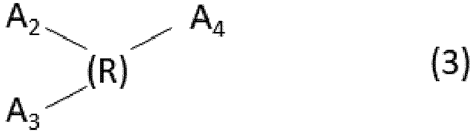

- A1 in the formula (1) denotes COOH. n denotes an integer in the range of 2 to 8. An acid satisfying the formula (1) may be tetrafluorosuccinic acid, hexafluoroglutaric acid, octafluoroadipic acid, dodecafluorosuberic acid, or hexadecafluorosebacic acid.
- At least one of A2 and A3 in the formula (2) denotes SO3H or PO3H2, and the other denotes an acidic group selected from the group consisting of SO3H, PO3H2, COOH, and OH. At least one of A2 and A3 denotes SO3H or PO3H2. R denotes a divalent organic group having 1 to 20 carbon atoms. An acid satisfying the formula (2) may be 4,4'-biphenyldisulfonic acid, methylenediphosphonic acid, 4-phosphonobenzoic acid, 4-phosphonobutyric acid, 3-amino-4-hydroxy-5-nitrobenzenesulfonic acid, 5-amino-1-naphthol-3-sulfonic acid, 6-amino-1-naphthol-3-sulfonic acid, 1-amino-2-naphthol-4-sulfonic acid, 2,2'-benzidinedisulfonic acid, or 4,4'-diaminostilbene-2,2'-disulfonic acid.
- Each of A2, A3, and A4 in the formula (3) denotes an acidic group selected from the group consisting of SO3H, PO3H2, COOH, and OH. At least one of A2, A3, and A4 denotes SO3H or PO3H2. R denotes a trivalent organic group having 1 to 20 carbon atoms. An acid satisfying the formula (3) may be nitrilotris, 1-hydroxyethane-1,1-diphosphonic acid, alendronic acid, N,N-Bis glycine or 4-sulfophthalic acid.
- Each of A2, A3, A4, and A5 in the formula (4) denotes an acidic group selected from the group consisting of SO3H, PO3H2, COOH, and OH. At least one of A2, A3, A4, and A5 denotes SO3H or PO3H2. R denotes a tetravalent organic group having 1 to 20 carbon atoms. An acid satisfying the formula (4) may be N,N,N',N'-ethylenediaminetetrakis, 2-phosphonobutane-1,2,4-tricarboxylic acid, or 2-hydroxy-1-(2-hydroxy-4-sulfo-1-naphthylazo)-3-naphthoic acid.
- The acidic group of an acid satisfying one of the formulae (1) to (4) can modify the surface of the
silicon oxide particles 21. Although an acid with only one acidic group can modify only one silicon oxide particle, an acid with two or more acidic groups as in the formulae (1) to (4) can modify a plurality of particles depending on the number of acidic groups. Consequently, theacid 24 can also bind particles together, increase the number of bonding sites between particles, and increase the strength of theporous layer 20. - The acid 24 in the
porous layer 20 can be identified as one of the formulae (1) to (4) by the elemental analysis of theporous layer 20 or by the separation and quantitative analysis of organic acids by ion-exclusion chromatography or the like. - It is desirable that the acid content of the porous layer be preferably in the range of 0.1% to 10% by mass of the silicon oxide particles contained in the porous layer. An acid content of less than 0.1% by mass tends to result in insufficient dispersion of particles, irregular arrangement of particles in the layer, and the layer with low strength. An acid content of more than 10% by mass tends to result in an increase in the empty spaces in the layer due to hindrance by the acid and result in the layer with low strength.
- The
silicon oxide particles 21 may be spherical, cocoon-like, barrel-shaped, disk-shaped, rod-like, acicular, square or rectangular, or chainlike particles. When theporous layer 20 is used as an antireflection layer, thesilicon oxide particles 21 can be hollow silicon oxide particles each having a vacancy within a shell as illustrated inFig. 2A or chainlike silicon oxide particles, that is, connected solid particles as illustrated inFig. 2B . It is desirable that thesilicon oxide particles 21 be silicon oxide particles formed by a wet process. This is because silicon oxide particles formed by a wet process have a larger number of silanol groups (Si-OH) on the surface of the particles and therefore tend to interact more strongly with the acid 24 than silicon oxide particles formed by a dry process. - Hollow silicon oxide particles can decrease the refractive index of the
porous layer 20 containing the particles due to air (refractive index 1.0) in the vacancies. - Hollow silicon oxide particles can be produced by a known method, for example, described in
Japanese Patent Laid-Open No. 2001-233611 Japanese Patent Laid-Open No. 2008-139581 silicon oxide particles 21 are hollow particles, a coating liquid is applied to a substrate and is dried to form layers of the hollowsilicon oxide particles 21 stacked in the direction perpendicular to the surface of thesubstrate 10, as illustrated inFig. 2A . - The hollow silicon oxide particles preferably have an average particle size in the range of 15 to 300 nm, more preferably 30 to 80 nm. An average particle size of less than 15 nm makes it difficult to consistently produce the particles. An average particle size of more than 300 nm tends to result in a large void between particles and scattering by the silicon oxide particles. However, when the
porous layer 20 is not used as an antireflection film, the average particle size is not necessarily 300 nm or less. - The average particle size of hollow silicon oxide particles is an average Feret diameter. The average Feret diameter can be determined by image processing of a transmission electron micrograph of hollow silicon oxide particles contained in the coating liquid. The image processing may be commercial image processing, such as image Pro PLUS (manufactured by Media Cybernetics, Inc.). In a predetermined image region, the contrast can be appropriately adjusted if necessary, and the Feret diameter of each particle can be measured by particle measurement. The average value of a plurality of particles can be calculated.
- The thickness of the shell of each hollow silicon oxide particle ranges from 10% to 50%, preferably 20% to 35%, of the average particle size. A shell thickness of less than 10% results in particles with insufficient strength. A shell thickness of more than 50% results in a small ratio of the empty space to the cubic content of the particle; therefore, the effects of hollow silicon oxide particles cannot be produced, that is, a layer with a refractive index of 1.3 or less cannot be formed.
- Chainlike silicon oxide particles are secondary particles composed of a linearly or crookedly connected primary solid silicon oxide particles. The size of a chainlike particle can be expressed by a short diameter and a long diameter. The short diameter of a chainlike particle corresponds to the thickness of the chainlike particle, in other words, the average particle size of one primary particle. The short diameter can be calculated from the specific surface area of a chainlike particle extracted from a coating liquid determined by a nitrogen adsorption method. The chainlike silicon oxide particles preferably have an average short diameter in the range of 8 to 20 nm. A short diameter of less than 8 nm may result in an excessively large surface area of the
silicon oxide particles 21 and a layer with low reliability due to absorption of moisture and chemical substances from the atmosphere. On the other hand, an average short diameter of more than 20 nm may result in unstable dispersion in a solvent and poor coatability. - The long diameter of a chainlike silicon oxide particle corresponds to the length of a secondary particle. The long diameter of particles in a coating liquid can be determined by a dynamic light scattering method. The long diameter of the chainlike silicon oxide particles preferably ranges from 4 to 8 times the short diameter. A long diameter less than 4 times the short diameter may result in a dense layer with an insufficiently decreased refractive index. A long diameter more than 8 times results in a coating liquid with high viscosity and poor coatability and leveling.
- The short diameter and long diameter of chainlike silicon oxide particles in the layer can be calculated from a scanning electron micrograph. The short diameter and long diameter can be determined from an image taken with a scanning electron microscope.
- Primary particles constituting chainlike silicon oxide particles may have individual clearly observed shapes or deformed shapes due to fusion of particles. The primary particles can have individual clearly observed shapes. Primary particles constituting chainlike silicon oxide particles may be spherical, cocoon-like, or barrel-shaped and can be cocoon-like or barrel-shaped. Primary particles constituting chainlike silicon oxide particles are particularly preferably particles with a short diameter in the range of 8 to 20 nm and a long diameter in the range of 1.5 to 3.0 times the short diameter.
- The coating liquid may contain particles with shapes other than spherical, cocoon-like, barrel-shaped, disk-shaped, rod-like, acicular, and square or rectangular chainlike silicon oxide particles. However, an excessively high number of particles with shapes other than chainlike silicon oxide particles results in a high refractive index. It is desirable in terms of optical performance that such particles be added such that the refractive index does not exceed approximately 1.3.
- Regardless of their shapes, silicon oxide particles can have a surface that can be bound by a binder described later.
- The
inorganic binder 22 for binding silicon oxide particles can be a silicon oxide compound. The silicon oxide compound can be a cured product of a silicon oxide oligomer formed by hydrolysis and condensation of a silicate. - When the
inorganic binder 22 is an inorganic material of the same quality as silicon oxide particles, theinorganic binder 22 can increase the bond strength between particles, and the porous layer is less likely to deteriorate in the use environment. - It is desirable that the binder content of the porous layer be in the range of 5% to 20% by mass, more desirably 6% to 17% by mass, of the silicon oxide particles contained in the porous layer. A binder content of less than 5% by mass tends to result in the layer with low strength. A binder content of more than 20% by mass may result in an increased refractive index and a low-refractive-index layer with insufficient optical performance.
-
Fig. 3 illustrates an imaging apparatus including a lens barrel (interchangeable lens) as an optical apparatus including a member according to the present disclosure.Fig. 3 illustrates a digital single-lens reflex camera to which a lens barrel (interchangeable lens) is attached. - The term "optical apparatus", as used herein, refers to an apparatus with an optical system, such as a binocular, a microscope, a semiconductor exposure apparatus, or an interchangeable lens.
- The term "imaging apparatus", as used herein, refers to electronic equipment including an imaging device for receiving light passing through an optical device, for example, a camera system, such as a digital still camera or a digital camcorder, or a mobile phone. The imaging apparatus may also be a modular form mounted on electronic equipment, for example, a camera module.
- Although a
camera body 202 is coupled to alens barrel 201, which is an optical apparatus, inFig. 3 , thelens barrel 201 is an interchangeable lens detachably mounted on thecamera body 202. - Light from an object passes through an optical
system including lenses housing 220 of thelens barrel 201 and is received by an imaging device. A member according to the present disclosure can also be used as a lens constituting an optical system. - The
lens 205 is movably supported by aninner tube 204 relative to an outer tube of thelens barrel 201 for focusing and zooming. - In the observation period before photographing, light from an object is reflected by a
main mirror 207 in ahousing 221 of the camera body, passes through aprism 211, and then provides the photographer with an image to be photographed through a viewing lens 212. Themain mirror 207 is a half mirror, for example. Light transmitted through the main mirror is reflected by a sub-mirror 208 in the direction of an autofocusing (AF)unit 213, and the reflected beam is used for focusing, for example. Themain mirror 207 is attached to and supported by amain mirror holder 240 by adhesion or the like. For photographing, themain mirror 207 and the sub-mirror 208 are moved out of the optical path by a driving mechanism (not shown), ashutter 209 is opened, and an optical image to be photographed incident from thelens barrel 201 is focused on animaging device 210. Furthermore, thediaphragm 206 is configured to change the aperture area and thereby change the brightness and the depth of focus while photographing. - A member according to the present disclosure can be used as a lens constituting an optical system, suppress reflection and scattering in the optical system, and provide a good image.
- Furthermore, due to the
porous layer 20 with high mechanical strength, a member according to the present disclosure is suitable for alens filter 250 to be installed on the outermost side of the optical system. Depending its type, thelens filter 250 has a function of protecting a lens or producing soft, color tone change, polarization, light reduction, and other effects on an image thus formed.Fig. 4 illustrates an example of thelens filter 250. Thelens filter 250 includes a member (filter member) 252 according to the present disclosure fitted into aframe 251 provided with a mountingportion 253, such as a screw thread or a bayonet mount, for mounting thelens filter 250 on thehousing 220 of the interchangeable lens. Thefilter member 252 has theporous layer 20 opposite the mountingportion 253 of theframe 251. When thelens filter 250 is mounted on thehousing 220, theporous layer 20 is positioned on the light incident surface. - A member according to the present disclosure can be adopted as a light-transmitting member of a face shield.
Fig. 5A is a schematic view of a face shield 60. The face shield 60 includes a light-transmittingmember 61 and aholder 67 for holding the light-transmittingmember 61. Theholder 67 has a structure for fixing the light-transmittingmember 61 to the user such that the light-transmittingmember 61 covers at least part of user's face. Theholder 67 includes a fixingportion 65 to which the light-transmittingmember 61 is fixed, and a supportingportion 66 for fixing the fixingportion 65 to the user. The supportingportion 66 is connected to the fixingportion 65. The fixingportion 65 is rod-like, and a peripheral portion of the light-transmittingmember 61 is fixed to a side surface of the fixingportion 65 with a fixingcomponent 69, such as a pin or screw. The fixingcomponent 69 can pass through anotch 91 and/or ahole 92 of the light-transmittingmember 61 illustrated inFig. 5B . The belt-like supportingportion 66 is attached to a wearer and supports the fixingportion 65. The light-transmittingmember 61 of the face shield 60 covers at least one or all of the eyes, nose, and mouth of the user, for example. - The outer surface (a surface opposite the face side) of the light-transmitting
member 61 of the face shield 60 can be a front surface, and the inner surface (the surface on the face side) can be a back surface. A light source on the outer surface side can be a main factor of reflected beam, and the porous layer can face the outer surface side to produce antireflection effects. Furthermore, when the face shield 60 is used, scratches are more likely to occur on the outer surface than on the inner surface. Thus, considering the scratch resistance of the light-transmittingmember 61, the porous layer can be provided on the outer surface side. When the porous layer is provided on both sides, the porous layer on the outer surface side can be thicker than the porous layer on the inner surface side. - The face shield 60 may be provided with a
ventilation fan 68 for ventilating the atmosphere adjacent to the light-transmittingmember 61. In this example, theventilation fan 68 is provided inside the holder 67 (fixing portion 65). - The use of the face shield 60 according to the present example not only protects the face of the wearer but also has the effects of improving the work efficiency of the wearer due to good visibility of the light-transmitting
member 61 and allowing a person who faces the wearer to easily recognize the face and expression of the wearer. - Although the face shield has been described in
Fig. 5 , a member according to the present disclosure is also suitable for a light-transmitting member of a shield partition. - Next, a coating liquid used to produce the
porous layer 20 is described, and then a method for manufacturing themember 1 is described. - A coating liquid contains the
silicon oxide particles 21, theacid 24, and a component serving as theinorganic binder 22, which constitute theporous layer 20, and an organic solvent. - The
silicon oxide particles 21 and theacid 24 are described above. - As illustrated in
Figs. 2A and 2B , theporous layer 20 includes thesilicon oxide particles 21 stacked on the surface of thesubstrate 10. A layer composed of unevenly arrangedsilicon oxide particles 21 tends to have an uneven stress distribution and decreased strength. Thus, it is desirable that thesilicon oxide particles 21 be aligned to form theporous layer 20 with high strength. - The arrangement of the
silicon oxide particles 21 depends mainly on the dispersion state of thesilicon oxide particles 21 in a coating liquid for forming theporous layer 20 containing the particles and the dispersion state of thesilicon oxide particles 21 while a coating film is formed after the coating liquid is applied to the substrate. - The
silicon oxide particles 21 uniformly dispersed in the coating liquid enables thesilicon oxide particles 21 to be uniformly applied to thesubstrate 10 and tends to result in better arrangement of thesilicon oxide particles 21 in the formed layer. When thesilicon oxide particles 21 in the coating liquid are dispersed in an aggregated state under the influence of the dispersion medium or the component serving as theinorganic binder 22, the particles in the aggregated state are applied to thesubstrate 10 and are poorly aligned. - Even when the
silicon oxide particles 21 in the coating liquid have a good dispersion state, aggregation of thesilicon oxide particles 21 during a drying process after the coating liquid is applied to the substrate disturbs the arrangement of thesilicon oxide particles 21 in the layer. - Thus, to form a layer with high strength, it is desirable that the
silicon oxide particles 21 be uniformly dispersed in the coating liquid and that thesilicon oxide particles 21 do not aggregate in the drying process of the coating liquid applied to thesubstrate 10. - The coating liquid used to produce the
porous layer 20 according to the present disclosure contains at least one acid selected from the group of acids listed in the formulae (1) to (4), and the surface of thesilicon oxide particles 21 in the coating liquid is modified with theacid 24. The modification with the acid 24 causes thesilicon oxide particles 21 to be charged and repel each other, suppresses aggregation of the particles, and uniformly disperses the particles. This state is maintained in the drying process of the coating liquid applied to the substrate. Thus, a coating liquid can be used to form a layer with high strength composed of regularly and densely arrangedsilicon oxide particles 21. - The
acid 24 preferably has a molecular weight in the range of 100 to 360. A molecular weight of less than 100 tends to result in difficult application due to increased viscosity and the coating liquid with low temporal stability. A molecular weight of more than 360 results in the presence of an acid with a high molecular weight between the particles and tends to result in a large empty space in the layer and scattering. - The
acid 24 content preferably ranges from 0.05% to 10% by mass, more preferably 0.1% to 2.0% by mass, of the silicon oxide particles. An acid 24 content of the coating liquid below 0.05% by mass of the silicon oxide particles tends to make it difficult to prevent aggregation of thesilicon oxide particles 21 after the coating liquid is applied to the substrate. Alternatively, due to the influence of the solvent and a component serving as a binder in the coating liquid, thesilicon oxide particles 21 tend to have low dispersion stability, and the coating liquid tends to become more viscous or form a gel with time. Theacid 24 constituting 10% by mass of the silicon oxide particles disturbs the arrangement of thesilicon oxide particles 21, increases the number ofempty spaces 23, and decreases the strength. - The
acid 24 preferably has an acid dissociation constant in the range of -1.2 to 2 pKa, more preferably -1.2 to 0.3 pKa. An acid dissociation constant of less than -1.2 pKa tends to result in irregular arrangement of thesilicon oxide particles 21 during the drying process after application to thesubstrate 10 and the layer with low strength. An acid dissociation constant of more than 2 pKa tends to result in poor dispersion of thesilicon oxide particles 21 in the coating liquid, poor arrangement in the layer, and the layer with low strength. - The
acids 24 represented by the formulae (1) to (4) are mostly safe while handling of raw materials and are mostly solid, and are easy to handle. - The component serving as the
inorganic binder 22 can be a silicon oxide oligomer. Although silicon oxide particles originally have silanol (Si-OH) groups on the surface, the number of silanol groups on the surface can be increased by mixing with a silicon oxide oligomer in the coating liquid. Consequently, thesilicon oxide particles 21 are more easily bound on the surface. When the coating liquid is applied and dried, the silicon oxide oligomer forms silicon oxide, fixes chainlikesilicon oxide particles 21 in contact with each other, and can provide a layer with high scratch resistance. - In a coating liquid, the component serving as the
inorganic binder 22 preferably constitutes 0.2% to 20% by mass, more preferably 0.2% to 17% by mass, of thesilicon oxide particles 21. When the component serving as theinorganic binder 22 constitutes less than 0.2% by mass of thesilicon oxide particles 21, thesilicon oxide particles 21 is insufficiently dispersed in the dispersion liquid, and the layer tends to have low strength. When the component serving as theinorganic binder 22 constitutes more than 20% by mass of thesilicon oxide particles 21, the inorganic binder disturbs the arrangement of the particles, and the layer tends to more strongly scatter visible light and have an increased refractive index. - An organic solvent that can be used in the coating liquid may be any solvent that does not precipitate the
silicon oxide particles 21 or drastically increase the viscosity of the coating liquid. Examples of such a solvent include the following solvents. Monohydric alcohols, such as methanol, ethanol, 1-propanol, 2-propanol, 1-butanol, 2-butanol, 2-methylpropanol, 1-pentanol, 2-pentanol, cyclopentanol, 2-methylbutanol, 3-methylbutanol, 1-hexanol, 2-hexanol, 3-hexanol, 4-methyl-2-pentanol, 2-methyl-1-pentanol, 2-ethylbutanol, 2,4-dimethyl-3-pentanol, 3-ethylbutanol, 1-heptanol, 2-heptanol, 1-octanol, and 2-octanol. Dihydric or polyhydric alcohols, such as ethylene glycol and triethylene glycol. Ether alcohols, such as methoxyethanol, ethoxyethanol, propoxyethanol, isopropoxyethanol, butoxyethanol, 1-methoxy-2-propanol, 1-ethoxy-2-propanol, 1-propoxy-2-propanol, and 3-methoxy-1-butanol; and ethers, such as dimethoxyethane, diglyme (diethylene glycol dimethyl ether), tetrahydrofuran, dioxane, diisopropyl ether, dibutyl ether, and cyclopentyl methyl ether. Esters, such as ethyl formate, ethyl acetate, n-butyl acetate, methyl lactate, ethyl lactate, ethylene glycol monomethyl ether acetate, ethylene glycol monoethyl ether acetate, ethylene glycol monobutyl ether acetate, and propylene glycol monomethyl ether acetate. Aliphatic and alicyclic hydrocarbons, such as n-hexane, n-octane, cyclohexane, cyclopentane, and cyclooctane. Aromatic hydrocarbons, such as toluene, xylene, and ethylbenzene. Ketones, such as acetone, methyl ethyl ketone, methyl isobutyl ketone, cyclopentanone, and cyclohexanone. Chlorinated hydrocarbons, such as chloroform, methylene chloride, carbon tetrachloride, and tetrachloroethane. Aprotic polarized solvents, such as N-methylpyrrolidone, N,N-dimethylformamide, N,N-dimethylacetamide, and ethylene carbonate. Two or more of these solvents may be used in combination. - From the perspectives of the dispersibility of the
silicon oxide particles 21 and the coating performance of the coating liquid, 30% or more by mass of the solvent in the coating liquid can be a water-soluble solvent having 4 to 6 carbon atoms and a hydroxy group. In particular, at least one solvent selected from the group consisting of ethoxyethanol, propoxyethanol, isopropoxyethanol, butoxyethanol, 1-methoxy-2-propanol, 1-ethoxy-2-propanol, 1-propoxy-2-propanol, ethyl lactate, and 3-methoxy-1-butanol can be contained. The use of these solvents reduces radial coating marks while coating and residual liquid around the substrate and improves coatability. - A method for manufacturing the
member 1 according to the present disclosure includes the steps of applying a coating liquid to thesubstrate 10 and drying and/or baking thesubstrate 10 to which the coating liquid has been applied. - The coating liquid may be applied to the
substrate 10 by a spin coating method, a blade coating method, a roll coating method, a slit coating method, a printing method, a gravure coating method, or a dip coating method. A member with a three-dimensionally complicated shape, such as a concave surface, can be produced by the spin coating method, which facilitates coating with a uniform thickness. - The drying and/or baking step is the step of removing the organic solvent and bonding the
silicon oxide particles 21 without disturbing the arrangement thereof to form theporous layer 20. The drying and/or baking step is preferably performed in the temperature range of 20°C to 200°C, depending on the heat resistance temperature of thesubstrate 10. The time of the drying and/or baking step may be such that the organic solvent in the layer can be removed without any influence on thesubstrate 10 and preferably ranges from 5 minutes to 200 hours, more preferably 30 minutes to 24 hours. - In Examples 1 to 18, a coating liquid for forming the
porous layer 20 was prepared by the following method, and a porous layer was formed on a substrate to prepare themember 1 with theporous layer 20. The coating liquid and theporous layer 20 were examined as described below. - A coating liquid was dropped on a polished surface of a glass substrate (φ30 mm, 1 mm in thickness, synthetic quartz with one polished surface) and was spread with a spin coater such that the
porous layer 20 had a thickness of approximately 110 nm. The appearance of the layer containing particles was visually inspected for a defect with an optical microscope and was rated in accordance with the following criteria. - A: No uneven coating is observed.
- B: A few inconspicuous drop marks and foreign substances are observed.
- C: Significant uneven coating, such as uneven streaks, due to foreign substances is observed with poor appearance.
- The rating A was judged to be excellent coatability, and the rating B was judged to be good coatability.
- The
porous layer 20 was formed on a polished surface of a glass substrate (φ30 mm, 1 mm in thickness, synthetic quartz with one polished surface). A polyester wiper (Alpha Wiper TX1009 manufactured by Texwipe) was moved reciprocally 50 times at a load of 300 g/cm2 on the surface of theporous layer 20. The appearance was evaluated with an optical microscope. The evaluation criteria were as follows: - A: Little change in appearance is observed.
- B: A small change in appearance is observed, and a small linear scratch or the like is observed.
- C: A significant change in appearance is observed, and linear scratches and peeling are observed.
- In the present disclosure, the rating A was judged to be very high strength, and the rating B was judged to be high strength without problems.
- The
porous layer 20 containing particles was formed on a polished surface of a glass substrate (φ30 mm, 1 mm in thickness, synthetic quartz with one polished surface). Light was incident on theporous layer 20 using a spectroscopic ellipsometer (VASE, manufactured by J. A. Woollam Japan Co., Inc.). The reflected beam was measured in the wavelength range of 380 to 800 nm to calculate a refractive index. The refractive index at a wavelength of 550 nm was rated in accordance with the following criteria. - A: 1.24 or less
- B: more than 1.24 and 1.30 or less
- C: more than 1.30
- The rating A or B was judged that the porous layer was suitable for a low-refractive-index layer.
- A glass substrate (φ30 mm, 1 mm in thickness, synthetic quartz with polished surfaces on both sides) was placed in a substrate holder. An illuminometer (T-10M manufactured by Konica Minolta Sensing) was installed in the substrate holder. While the illuminance was measured, the surface of the substrate was irradiated with white light such that the illuminance in the vertical direction was 4000 lux. Next, a member having the
porous layer 20 on the glass substrate was placed in a substrate holder such that white light was incident on theporous layer 20 side. The member was tilted at 45 degrees and was photographed with a camera (lens: EF50 mm F2.5 Compact Macro manufactured by CANON KABUSHIKI KAISHA, camera: EOS-70D manufactured by CANON KABUSHIKI KAISHA) in the direction normal to the surface opposite the surface to be irradiated. The imaging conditions of the camera were ISO 400, white balance: fair weather, diaphragm: 10, and a shutter speed: 10 seconds. The average luminance of four positions in 700 pixels x 700 pixels in a captured image was calculated as a scattering value. - In the present disclosure, the
porous layer 20 with a scattering value of 25 or less as calculated by this method was judged to have low scattering. - Pure water was dropped on the surface of the porous layer opposite the substrate, and the contact angle of the pure water was measured at a room temperature of 23°C and at a humidity in the range of 40%RH to 45%RH. The contact angle was measured by taking an image 1000 ms after the pure water was dropped.
- While 1-ethoxy-2-propanol was added to 400 g of an isopropyl alcohol dispersion liquid of hollow silicon oxide particles (Thrulya 1110 manufactured by JGC Catalysts and Chemicals Ltd., average particle size: approximately 50 nm, shell thickness: approximately 10 nm, solid content: 20.5% by mass), isopropyl alcohol was evaporated by heating. The isopropyl alcohol was evaporated to a solid content of 19.5% by mass. Thus, 420 g of a 1E2P solvent-substituted liquid of hollow silicon oxide particles (hereinafter referred to as a solvent-substituted liquid 1) was prepared. An acid was added to the solvent-substituted
liquid 1 such that the mass ratio of hollow silicon oxide particles:acid component was 400:1. Thus, adispersion liquid 1 was prepared. The acid added was an acid with two acidic groups (tetrafluorosuccinic acid manufactured by Tokyo Chemical Industry Co., Ltd.). - In a separate container, 13.82 g of ethanol and an aqueous nitric acid (concentration: 3%) were added to 12.48 g of ethyl silicate. The mixture was stirred at room temperature for 10 hours to prepare a silica sol 1 (solid content: 11.5% by mass). Gas chromatography showed that the raw material ethyl silicate was completely reacted.
- The
dispersion liquid 1 was diluted with ethyl lactate to a solid content of 3.9% by mass. Thesilica sol 1 was then added to thedispersion liquid 1 such that the ratio of hollow silicon oxide particles: silica sol component was 100:11. The mixture was then mixed by stirring at room temperature for 2 hours to prepare acoating liquid 1 containing hollow silicon oxide particles. - The
coating liquid 1 was dropped on a glass substrate and was spread with a spin coater such that the resulting porous layer had a thickness of approximately 110 nm, and was then baked in a thermostatic oven at 140°C for 30 minutes to prepare a member 1-1 including a porous layer 20-1 containing particles. The contact angle of pure water on the surface of the porous layer 20-1 opposite the substrate was 10 degrees. - An acid was added to the solvent-substituted
liquid 1 such that the ratio of hollow silicon oxide particles:acid component was 400:1. Thus, a dispersion liquid 2 was prepared. The acid added was an acid with two acidic groups (octafluoroadipic acid manufactured by Tokyo Chemical Industry Co., Ltd.). - The dispersion liquid 2 was diluted with ethyl lactate to a solid content of 3.9% by mass. The
silica sol 1 was then added to the dispersion liquid 2 such that the mass ratio of hollow silicon oxide particles: silica sol component was 100:11. The mixture was then mixed by stirring at room temperature for 2 hours to prepare a coating liquid 2 containing hollow silicon oxide particles. - The coating liquid 2 was dropped on a glass substrate and was spread with a spin coater such that the resulting porous layer had a thickness of approximately 110 nm, and was then baked in a thermostatic oven at 140°C for 30 minutes to prepare a member 1-2 including a porous layer 20-2 containing particles. The contact angle of pure water on the surface of the porous layer 20-2 opposite the substrate was 10 degrees.
- While 1-methoxy-2-propanol (hereinafter abbreviated to PGME) was added to 350 g of an aqueous dispersion liquid of hydrophilic silicon oxide particles (PL-1 manufactured by Fuso Chemical Co., Ltd., average particle size: approximately 15 nm, long diameter/short diameter = 2.6, solid content: 12% by mass), water was evaporated by heating. The water was evaporated to a solid content of 15% by mass. Thus, 280 g of a PGME solvent-substituted liquid of hydrophilic silicon oxide particles (hereinafter referred to as a solvent-substituted liquid 2) was prepared. An acid was added to the solvent-substituted liquid 2 such that the mass ratio of hydrophilic silicon oxide particles:acid component was 100:1. Thus, a dispersion liquid 3 was prepared. The acid added was an acid with three acidic groups (nitrilotris manufactured by Tokyo Chemical Industry Co., Ltd.).
- The dispersion liquid 3 was diluted with 1-propoxy-2-propanol to a solid content of 4.5% by mass. The
silica sol 1 was then added to the dispersion liquid 3 such that the ratio of hydrophilic silicon oxide particles: silica sol component was 100:6. The mixture was then mixed by stirring at room temperature for 2 hours to prepare a coating liquid 3 containing hydrophilic silicon oxide particles. - The coating liquid 3 was dropped on a glass substrate and was spread with a spin coater such that the resulting porous layer had a thickness of approximately 110 nm, and was then baked in a thermostatic oven at 140°C for 30 minutes to prepare a member 1-3 including a porous layer 20-3 containing chainlike silicon oxide particles. The contact angle of pure water on the surface of the porous layer 20-3 opposite the substrate was 6 degrees.
- An acid was added to the solvent-substituted liquid 2 such that the mass ratio of hydrophilic silicon oxide particles:acid component was 200:1. Thus, a dispersion liquid 4 was prepared. The acid added was an acid with four acidic groups (N,N,N',N'-ethylenediaminetetrakis manufactured by Tokyo Chemical Industry Co., Ltd.).
- The dispersion liquid 4 was diluted with 1-propoxy-2-propanol to a solid content of 4.5% by mass. The
silica sol 1 was then added to the dispersion liquid 4 such that the mass ratio of hydrophilic silicon oxide particles: silica sol component was 100:6. The mixture was then mixed by stirring at room temperature for 2 hours to prepare a coating liquid 4 containing hydrophilic silicon oxide particles. - The coating liquid 4 was dropped on a glass substrate and was spread with a spin coater such that the resulting porous layer had a thickness of approximately 110 nm, and was then baked in a thermostatic oven at 140°C for 30 minutes to prepare a member 1-4 including a porous layer 20-4 containing chainlike silicon oxide particles. The contact angle of pure water on the surface of the porous layer 20-4 opposite the substrate was 7 degrees.
- An acid was added to the solvent-substituted liquid 2 such that the mass ratio of hydrophilic silicon oxide particles:acid component was 200:1. Thus, a dispersion liquid 5 was prepared. The acid added was an acid with two acidic groups (tetrafluorosuccinic acid manufactured by Tokyo Chemical Industry Co., Ltd.).
- The dispersion liquid 5 was diluted with 1-propoxy-2-propanol to a solid content of 4.5% by mass. The
silica sol 1 was then added to the dispersion liquid 5 such that the mass ratio of hydrophilic silicon oxide particles: silica sol component was 100:6. The mixture was then mixed by stirring at room temperature for 2 hours to prepare a coating liquid 5 containing hydrophilic silicon oxide particles. - The coating liquid 5 was dropped on a glass substrate and was spread with a spin coater such that the resulting porous layer had a thickness of approximately 110 nm, and was then baked in a thermostatic oven at 140°C for 30 minutes to prepare a member 1-5 including a porous layer 20-5 containing chainlike silicon oxide particles. The contact angle of pure water on the surface of the porous layer 20-5 opposite the substrate was 7 degrees.
- An acid was added to the solvent-substituted
liquid 1 such that the mass ratio of hollow silicon oxide particles:acid component was 500:1. Thus, a dispersion liquid 6 was prepared. The acid added was an acid with two acidic groups (tetrafluorosuccinic acid manufactured by Tokyo Chemical Industry Co., Ltd.). - The dispersion liquid 6 was diluted with ethyl lactate to a solid content of 3.9% by mass. The
silica sol 1 was then added to the dispersion liquid 6 such that the mass ratio of hollow silicon oxide particles: silica sol component was 100:6. The mixture was then mixed by stirring at room temperature for 2 hours to prepare a coating liquid 6 containing hollow silicon oxide particles. - The coating liquid 6 was dropped on a glass substrate and was spread with a spin coater such that the resulting porous layer had a thickness of approximately 110 nm, and was then baked in a thermostatic oven at 140°C for 30 minutes to prepare a member 1-6 including a porous layer 20-6 containing particles. The contact angle of pure water on the surface of the porous layer 20-6 opposite the substrate was 10 degrees.
- An acid was added to the solvent-substituted
liquid 1 such that the ratio of hollow silicon oxide particles:acid component was 250:1. Thus, a dispersion liquid 7 was prepared. The acid added was an acid with two acidic groups (octafluoroadipic acid manufactured by Tokyo Chemical Industry Co., Ltd.). - The dispersion liquid 7 was diluted with ethyl lactate to a solid content of 3.9% by mass. The
silica sol 1 was then added to the dispersion liquid 7 such that the mass ratio of hollow silicon oxide particles: silica sol component was 100:11. The mixture was then mixed by stirring at room temperature for 2 hours to prepare a coating liquid 7 containing hollow silicon oxide particles. - The coating liquid 7 was dropped on a glass substrate and was spread with a spin coater such that the resulting porous layer had a thickness of approximately 110 nm, and was then baked in a thermostatic oven at 140°C for 30 minutes to prepare a member 1-7 including a porous layer 20-7 containing particles. The contact angle of pure water on the surface of the porous layer 20-7 opposite the substrate was 10 degrees.
- An acid was added to the solvent-substituted liquid 2 such that the ratio of hydrophilic silicon oxide particles:acid component was 100:1. Thus, a dispersion liquid 8 was prepared. The acid added was an acid with two acidic groups (tetrafluorosuccinic acid manufactured by Tokyo Chemical Industry Co., Ltd.).
- The dispersion liquid 8 was diluted with 1-propoxy-2-propanol to a solid content of 4.5% by mass. The
silica sol 1 was then added to the dispersion liquid 8 such that the ratio of hydrophilic silicon oxide particles: silica sol component was 100:6. The mixture was then mixed by stirring at room temperature for 2 hours to prepare a coating liquid 8 containing hydrophilic silicon oxide particles. - The coating liquid 8 was dropped on a glass substrate and was spread with a spin coater such that the resulting porous layer had a thickness of approximately 110 nm, and was then baked in a thermostatic oven at 140°C for 30 minutes to prepare a member 1-8 including a porous layer 20-8 containing chainlike silicon oxide particles. The contact angle of pure water on the surface of the porous layer 20-8 opposite the substrate was 7 degrees.
- An acid was added to the solvent-substituted liquid 2 such that the ratio of hydrophilic silicon oxide particles:acid component was 10:1. Thus, a dispersion liquid 9 was prepared. The acid added was an acid with two acidic groups (tetrafluorosuccinic acid manufactured by Tokyo Chemical Industry Co., Ltd.).
- The dispersion liquid 9 was diluted with 1-propoxy-2-propanol to a solid content of 4.5% by mass. The
silica sol 1 was then added to the dispersion liquid 9 such that the mass ratio of hydrophilic silicon oxide particles: silica sol component was 100:6. The mixture was then mixed by stirring at room temperature for 2 hours to prepare a coating liquid 9 containing hydrophilic silicon oxide particles. - The coating liquid 9 was dropped on a glass substrate and was spread with a spin coater such that the resulting porous layer had a thickness of approximately 110 nm, and was then baked in a thermostatic oven at 140°C for 30 minutes to prepare a member 1-9 including a porous layer 20-9 containing particles. The contact angle of pure water on the surface of the porous layer 20-9 opposite the substrate was 6 degrees.
- An acid was added to the solvent-substituted
liquid 1 such that the ratio of hollow silicon oxide particles:acid component was 200:1. Thus, adispersion liquid 10 was prepared. The acid added was an acid with two acidic groups (dodecafluorosuberic acid manufactured by Tokyo Chemical Industry Co., Ltd.). - 11.41 g of 1-propoxy-2-propanol and 4.5 g of methyl polysilicate (Methyl Silicate 53A manufactured by Colcoat Co., Ltd.) were slowly added to a separate container and were stirred at room temperature for 120 minutes to prepare a silica sol (hereinafter referred to as a silica sol 2).
- The
dispersion liquid 10 was diluted with 1-propoxy-2-propanol to a solid content of 3.9% by mass. The silica sol 2 was then added to thedispersion liquid 10 such that the mass ratio of hollow silicon oxide particles: silica sol component was 100:11. The mixture was then mixed by stirring at room temperature for 2 hours to prepare acoating liquid 10 containing hollow silicon oxide particles. - The
coating liquid 10 was dropped on a glass substrate and was spread with a spin coater such that the resulting porous layer had a thickness of approximately 110 nm, and was then baked in a thermostatic oven at 140°C for 30 minutes to prepare a member 1-10 including a porous layer 20-10 containing particles. The contact angle of pure water on the surface of the porous layer 20-10 opposite the substrate was 10 degrees. - An acid was added to the solvent-substituted
liquid 1 such that the ratio of hollow silicon oxide particles:acid component was 200:1. Thus, a dispersion liquid 11 was prepared. The acid added was an acid with two acidic groups (dodecafluorosuberic acid manufactured by Tokyo Chemical Industry Co., Ltd.). - The dispersion liquid 11 was diluted with ethyl lactate to a solid content of 3.9% by mass. The silica sol 2 was then added to the dispersion liquid 11 such that the mass ratio of hollow silicon oxide particles: silica sol component was 100:11. The mixture was then mixed by stirring at room temperature for 2 hours to prepare a coating liquid 11 containing hollow silicon oxide particles.
- The coating liquid 11 was dropped on a glass substrate and was spread with a spin coater such that the resulting porous layer had a thickness of approximately 110 nm, and was then baked in a thermostatic oven at 140°C for 30 minutes to prepare a member 1-11 including a porous layer 20-11 containing particles. The contact angle of pure water on the surface of the porous layer 20-11 opposite the substrate was 9 degrees.
- An acid was added to the solvent-substituted
liquid 1 such that the ratio of hollow silicon oxide particles:acid component was 250:1. Thus, a dispersion liquid 12 was prepared. The acid added was an acid with two acidic groups (dodecafluorosuberic acid manufactured by Tokyo Chemical Industry Co., Ltd.). - The dispersion liquid 12 was diluted with 3-methoxy-1-butanol to a solid content of 3.9% by mass. The
silica sol 1 was then added to the dispersion liquid 12 such that the mass ratio of hollow silicon oxide particles: silica sol component was 100:11. The mixture was then mixed by stirring at room temperature for 2 hours to prepare a coating liquid 12 containing hollow silicon oxide particles. - The coating liquid 12 was dropped on a glass substrate and was spread with a spin coater such that the resulting porous layer had a thickness of approximately 110 nm, and was then baked in a thermostatic oven at 140°C for 30 minutes to prepare a member 1-12 including a porous layer 20-12 containing particles. The contact angle of pure water on the surface of the porous layer 20-12 opposite the substrate was 8 degrees.
- An acid was added to the solvent-substituted
liquid 1 such that the ratio of hollow silicon oxide particles:acid component was 200:1. Thus, a dispersion liquid 13 was prepared. The acid added was an acid with two acidic groups (hexafluoroglutaric acid manufactured by Tokyo Chemical Industry Co., Ltd.). - The dispersion liquid 13 was diluted with 3-methoxy-1-butanol to a solid content of 3.9% by mass. The silica sol 2 was then added to the dispersion liquid 13 such that the mass ratio of hollow silicon oxide particles: silica sol component was 100:11. The mixture was then mixed by stirring at room temperature for 2 hours to prepare a coating liquid 13 containing hollow silicon oxide particles.
- The coating liquid 13 was dropped on a glass substrate and was spread with a spin coater such that the resulting porous layer had a thickness of approximately 110 nm, and was then baked in a thermostatic oven at 140°C for 30 minutes to prepare a member 1-13 including a porous layer 20-13 containing particles. The contact angle of pure water on the surface of the porous layer 20-13 opposite the substrate was 8 degrees.
- 400 g of an isopropyl alcohol dispersion liquid of hollow silicon oxide particles (Thrulya 1110 manufactured by JGC Catalysts and Chemicals Ltd., average particle size: approximately 50 nm, shell thickness: approximately 10 nm, solid content: 20.5% by mass) was mixed with 1-propoxy-2-propanol to prepare a dispersion liquid 14 with a solid content of 3.9% by mass.
- An acid was added to the dispersion liquid 14 such that the ratio of hollow silicon oxide particles:acid component was 250:1. The acid added was an acid with two acidic groups (dodecafluorosuberic acid manufactured by Tokyo Chemical Industry Co., Ltd.).
- Furthermore, the silica sol 2 was added such that the mass ratio of hollow silicon oxide particles: silica sol component was 100:11. The mixture was then mixed by stirring at room temperature for 2 hours to prepare a coating liquid 14 containing hollow silicon oxide particles.
- The coating liquid 14 was dropped on a glass substrate and was spread with a spin coater such that the resulting porous layer had a thickness of approximately 110 nm, and was then baked in a thermostatic oven at 140°C for 30 minutes to prepare a member 1-14 including a porous layer 20-14 containing particles. The contact angle of pure water on the surface of the porous layer 20-14 opposite the substrate was 10 degrees.
- 400 g of an isopropyl alcohol dispersion liquid of hollow silicon oxide particles (Thrulya 1110 manufactured by JGC Catalysts and Chemicals Ltd., average particle size: approximately 50 nm, shell thickness: approximately 10 nm, solid content: 20.5% by mass) was mixed with ethyl lactate to prepare a dispersion liquid 15 with a solid content of 3.9% by mass.
- An acid was added to the dispersion liquid 15 such that the ratio of hollow silicon oxide particles:acid component was 250:1. The acid added was an acid with two acidic groups (dodecafluorosuberic acid manufactured by Tokyo Chemical Industry Co., Ltd.).
- Furthermore, the silica sol 2 was added such that the mass ratio of hollow silicon oxide particles: silica sol component was 100:11. The mixture was then mixed by stirring at room temperature for 2 hours to prepare a coating liquid 15 containing hollow silicon oxide particles.
- The coating liquid 15 was dropped on a glass substrate and was spread with a spin coater such that the resulting porous layer had a thickness of approximately 110 nm, and was then baked in a thermostatic oven at 140°C for 30 minutes to prepare a member 1-15 including a porous layer 20-15 containing particles. The contact angle of pure water on the surface of the porous layer 20-15 opposite the substrate was 7 degrees.
- 200 g of an isopropyl alcohol dispersion liquid of hollow silicon oxide particles (Thrulya 1110 manufactured by JGC Catalysts and Chemicals Ltd., average particle size: approximately 50 nm, shell thickness: approximately 10 nm, solid content: 20.5% by mass) was mixed with 1-propoxy-2-propanol to prepare a dispersion liquid 16 with a solid content of 3.9% by mass.
- An acid was added to the dispersion liquid 16 such that the ratio of hollow silicon oxide particles:acid component was 200:1. The acid added was an acid with two acidic groups (dodecafluorosuberic acid manufactured by Tokyo Chemical Industry Co., Ltd.).
- Furthermore, the silica sol 2 was added such that the mass ratio of hollow silicon oxide particles: silica sol component was 100:11. The mixture was then mixed by stirring at room temperature for 2 hours to prepare a coating liquid 16 containing hollow silicon oxide particles.
- The coating liquid 16 was dropped on a glass substrate and was spread with a spin coater such that the resulting porous layer had a thickness of approximately 110 nm, and was then baked in a thermostatic oven at 140°C for 30 minutes to prepare a member 1-16 including a porous layer 20-16 containing particles. The contact angle of pure water on the surface of the porous layer 20-16 opposite the substrate was 9 degrees.
- 200 g of an isopropyl alcohol dispersion liquid of hollow silicon oxide particles (Thrulya 4110 manufactured by JGC Catalysts and Chemicals Ltd., average particle size: approximately 60 nm, shell thickness: approximately 10 nm, solid content: 20.5% by mass) was mixed with 1-propoxy-2-propanol to prepare a dispersion liquid 17 with a solid content of 3.9% by mass.
- An acid was added to the dispersion liquid 17 such that the ratio of hollow silicon oxide particles:acid component was 400:1. The acid added was an acid with two acidic groups (dodecafluorosuberic acid manufactured by Tokyo Chemical Industry Co., Ltd.).
- Furthermore, the silica sol 2 was added such that the mass ratio of hollow silicon oxide particles: silica sol component was 100:11. The mixture was then mixed by stirring at room temperature for 2 hours to prepare a coating liquid 17 containing hollow silicon oxide particles.
- The coating liquid 17 was dropped on a glass substrate and was spread with a spin coater such that the resulting porous layer had a thickness of approximately 110 nm, and was then baked in a thermostatic oven at 140°C for 30 minutes to prepare a member 1-17 including a porous layer 20-17 containing particles. The contact angle of pure water on the surface of the porous layer 20-17 opposite the substrate was 10 degrees.
- While 1-propoxy-2-propanol was added to 400 g of an isopropyl alcohol dispersion liquid of hollow silicon oxide particles (Thrulya 4110 manufactured by JGC Catalysts and Chemicals Ltd., average particle size: approximately 60 nm, shell thickness: approximately 10 nm, solid content: 20.5% by mass), isopropyl alcohol was evaporated by heating. The isopropyl alcohol was evaporated to a solid content of 19.5% by mass. Thus, 420 g of a 1P2P solvent-substituted liquid of hollow silicon oxide particles (hereinafter referred to as a solvent-substituted liquid 3) was prepared. An acid was added to the solvent-substituted liquid 3 such that the mass ratio of hollow silicon oxide particles:acid component was 400:1. Thus, a dispersion liquid 18 was prepared. The acid added was an acid with two acidic groups (tetrafluorosuccinic acid manufactured by Tokyo Chemical Industry Co., Ltd.).
- The dispersion liquid 18 was diluted with ethyl lactate to a solid content of 3.9% by mass. The silica sol 2 was then added to the dispersion liquid 18 such that the ratio of hollow silicon oxide particles: silica sol component was 100:11. The mixture was then mixed by stirring at room temperature for 2 hours to prepare a coating liquid 18 containing hollow silicon oxide particles.
- The coating liquid 18 was dropped on a glass substrate and was spread with a spin coater such that the resulting porous layer had a thickness of approximately 110 nm, and was then baked in a thermostatic oven at 140°C for 30 minutes to prepare a member 1-18 including a porous layer 20-18 containing particles. The contact angle of pure water on the surface of the porous layer 20-18 opposite the substrate was 8 degrees.
- An acid was added to the solvent-substituted liquid 2 such that the ratio of hollow silicon oxide particles:acid component was 100:1. Thus, a dispersion liquid 19 was prepared. The acid added was 3,3,3-trifluoropropionic acid (manufactured by Tokyo Chemical Industry Co., Ltd., number of acidic groups: 1).
- The dispersion liquid 19 was diluted with ethyl lactate to a solid content of 3.9% by mass. The
silica sol 1 was then added to the dispersion liquid 19 such that the mass ratio of hollow silicon oxide particles: silica sol component was 100:12. The mixture was then mixed by stirring at room temperature for 2 hours to prepare a coating liquid 19 containing hydrophilic silicon oxide particles. - The coating liquid 19 was dropped on a glass substrate and was spread with a spin coater such that the resulting porous layer had a thickness of approximately 110 nm, and was then baked in a thermostatic oven at 140°C for 30 minutes to prepare a member 1-19 including a porous layer 20-19 containing particles. The contact angle of pure water on the porous layer 20-19 was 21 degrees.
- An acid was added to the solvent-substituted
liquid 1 such that the mass ratio of hollow silicon oxide particles:acid component was 100:1. Thus, adispersion liquid 20 was prepared. The acid added was p-toluenesulfonic acid monohydrate (manufactured by Tokyo Chemical Industry Co., Ltd., number of acidic groups: 1). - The
dispersion liquid 20 was diluted with ethyl lactate to a solid content of 3.9% by mass. The silica sol 2 was then added to thedispersion liquid 20 such that the mass ratio of hollow silicon oxide particles: silica sol component was 100:12. The mixture was then mixed by stirring at room temperature for 2 hours to prepare acoating liquid 20 containing hollow silicon oxide particles. - The
coating liquid 20 was dropped on a glass substrate and was spread with a spin coater such that the resulting porous layer had a thickness of approximately 110 nm, and was then baked in a thermostatic oven at 140°C for 30 minutes to prepare a member 1-20 including a porous layer 20-20 containing particles. The contact angle of pure water on the porous layer 20-20 was 13 degrees. - Phosphoric acid (manufactured by Tokyo Chemical Industry Co., Ltd., number of acidic groups: 1) was added to the solvent-substituted
liquid 1 such that the mass ratio of hollow silicon oxide particles:acid component was 100:1. Thus, adispersion liquid 21 was prepared. - The
dispersion liquid 21 was diluted with ethyl lactate to a solid content of 3.9% by mass. Thesilica sol 1 was then added to thedispersion liquid 21 such that the mass ratio of hollow silicon oxide particles: silica sol component was 100:12. The mixture was then mixed by stirring at room temperature for 2 hours to prepare acoating liquid 21 containing hollow silicon oxide particles. - The
coating liquid 21 was dropped on a glass substrate and was spread with a spin coater such that the resulting porous layer had a thickness of approximately 110 nm, and was then baked in a thermostatic oven at 140°C for 30 minutes to prepare a member 1-21 including a porous layer 20-21 containing particles. The contact angle of pure water on the porous layer 20-21 was 15 degrees. - Table 1 shows the evaluation results of the
coating liquids 1 to 18 used in the examples and comparative examples and the members 1-1 to 1-18 produced using the coating liquids.Table 1 Silicon oxide particle Acid Evaluation results Number of acidic groups Formula Acidic group Designation pKa Addition amount (phr) Coatability Film strength Refractive index Scattering Example 1 Coating liquid 1 Hollow 2 (1) -COOH Tetrafluorosuccinic Acid -1.03 0.25 A A A 20 Example 2 Coating liquid2 Hollow 2 (1) -COOH Octafluoroadipic Acid 0.23 0.25 A A A 22 Example 3 Coating liquid3 Cocoon-like 3 (3) -PO3H2 Nitrilotris 0.56 1 B B B 25 Example 4 Coating liquid4 Chainlike 4 (4) -PO3H2 N,N,N',N'-Ethylenediaminetetrakis 0.13 0.5 A B B 25 Example 5 Coating liquid5 Chainlike 2 (2) -SO3H 4,4'-Biphenyldisulfonic Acid -1.14 0.5 A A B 24 Example 6 Coating liquid6 Hollow 2 (1) -COOH Tetrafluorosuccinic Acid -1.03 0.2 A A A 22 Example 7 Coating liquid7 Hollow 2 (1) -COOH Octafluoroadipic Acid 0.23 0.4 A A A 23 Example 8 Coating liquid8 Chainlike 2 (1) -COOH Tetrafluorosuccinic Acid -1.03 1 A A A 19 Example 9 Coating liquid9 Chainlike 2 (1) -COOH Tetrafluorosuccinic Acid -1.03 10 A A A 16 Example 10 Coating liquid 10 Hollow 2 (1) -COOH Dodecafluorosuberic Acid 0.23 0.5 A A A 22 Example 11 Coating liquid 11 Hollow 2 (1) -COOH Dodecafluorosuberic Acid 0.23 0.5 A A A 15 Example 12 Coating liquid 12 Hollow 2 (1) -COOH Dodecafluorosuberic Acid 0.23 0.4 A A A 20 Example 13 Coating liquid 13 Hollow 2 (1) -COOH Hexafluoroglutaric Acid 0.22 0.5 A A A 24 Example 14 Coating liquid 14 Hollow 2 (1) -COOH Dodecafluorosuberic Acid 0.23 0.4 A A A 21 Example 15 Coating liquid 15 Hollow 2 (1) -COOH Dodecafluorosuberic Acid 0.23 0.4 B A A 21 Example 16 Coating liquid 16 Hollow 2 (1) -COOH Dodecafluorosuberic Acid 0.23 0.5 A A A 17 Example 17 Coating liquid 17 Hollow 2 (1) -COOH Dodecafluorosuberic Acid 0.23 0.25 A B A 23 Example 18 Coating liquid 18 Hollow 2 (1) -COOH Dodecafluorosuberic Acid 0.23 0.25 A A A 20 Comparative example 1 Coating liquid 19 Hollow 1 - -COOH 3,3,3-Trifluoropropionic Acid 3.1 1 B C B 27 Comparative example 2 Coating liquid 20 Hollow 1 - -SO3H p-Toluenesulfonic Acid Monohydrate -2.8 1 B C B 34 Comparative example 3 Coating liquid 21 Hollow 1 - -PO3H2 Phosphoric acid 2.1 1 C C B 35 - The results in Table 1 show that Examples 1 to 18 had high film strength while maintaining a low refractive index. Examples 1 to 18 also had a scattering value of 25 or less and had sufficient performance as optical functional films.
- By contrast, Comparative Examples 1 to 3 had low film strength and a high scattering value of 25 or more. This probably shows that with an acid with only one acidic group it was difficult to maintain a highly dispersed state as the solvent evaporates during the formation of the coating film, thus resulting in irregular arrangement, linear scratches, and peeling. The irregular arrangement also probably resulted in a high scattering value.
- As described above, the present disclosure can provide a member having a porous layer containing silicon oxide particles and having a low refractive index and high film strength.
- Although optical members are mainly described above, a member according to the present disclosure can be used for other applications. Applications other than optical members may only require good coatability and high film strength and do not necessarily require a low refractive index or scattering value. For example, these applications include heat-insulating members and insulating members.
- The present disclosure provides a member (1) having a porous layer (20) containing particles and having a low refractive index and high film strength and a coating liquid for forming a porous layer (20) containing particles, wherein the porous layer (20) contains a plurality of silicon oxide particles (21) bound by an inorganic binder (22) and at least one acid (24).
Claims (14)
- A member (1) having a substrate and a porous layer (20) on the substrate (10), whereinthe porous layer (20) contains a plurality of silicon oxide particles (21) bound by an inorganic binder (22) and at least one acid (24) selected from the group consisting of the following formulae (1) to (4):


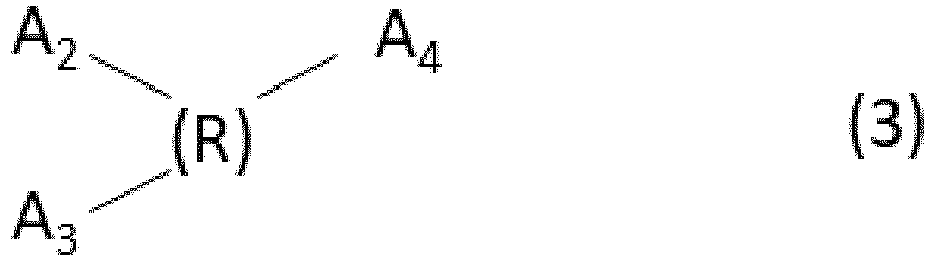
 whereinA1 in the formula (1) denotes COOH, and n denotes an integer in the range of 2 to 8,one of A2 and A3 in the formula (2) denotes SO3H or PO3H2, and the other denotes an acidic group selected from the group consisting of SO3H, PO3H2, COOH, and OH, and R denotes a divalent organic group having 1 to 20 carbon atoms,at least one of A2, A3, and A4 in the formula (3) denotes SO3H or PO3H2, and the other denotes an acidic group selected from the group consisting of SO3H, PO3H2, COOH, and OH, and R denotes a trivalent organic group having 1 to 20 carbon atoms, andat least one of A2, A3, A4, and A5 in the formula (4) denotes SO3H or PO3H2, and the other denotes an acidic group selected from the group consisting of SO3H, PO3H2, COOH, and OH, and R denotes a tetravalent organic group having 1 to 20 carbon atoms.
 - The member (1) according to Claim 1, wherein the silicon oxide particles (21) are hollow silicon oxide particles or chainlike silicon oxide particles.
- The member (1) according to Claim 1 or 2 , wherein the inorganic binder (22) is a silicon oxide compound.
- The member (1) according to any one of Claims 1 to 3, wherein the porous layer (20) has a refractive index in the range of 1.20 to 1.30.
- The member (1) according to any one of Claims 1 to 4, further comprising an intermediate layer (40) between the substrate (10) and the porous layer (20) , wherein the intermediate layer (40) includes an inorganic compound layer or a polymer layer.
- The member (1) according to any one of Claims 1 to 5, further comprising an antifouling layer, and the antifouling layer is one of a fluoropolymer-containing layer, a fluorosilane monolayer, and a layer containing titanium oxide particles.
- The member (1) according to any one of Claims 1 to 5, further comprising a hydrophilic layer, and the hydrophilic layer is a layer containing a polymer with a zwitterionic hydrophilic group.
- An optical apparatus comprising:a housing (220); andan optical system composed of a plurality of lenses (203, 205) in the housing (220), whereinthe lenses (203, 205) are the members (1) according to any one of Claims 1 to 7.
- An imaging apparatus comprising:a housing (220);an optical system composed of a plurality of lenses (203, 205) in the housing (220); andan imaging device (210) for receiving light passing through the optical system, whereinthe lenses (203, 205) are the members (1) according to any one of Claims 1 to 7.
- A lens filter (250) comprising:a frame (251); anda filter member (252) supported by the frame (251), whereinthe filter member (252) is the member (1) according to any one of Claim 1 to 7.
- A shield (60) comprising:a light-transmitting member (61); anda holder (67) for holding the light-transmitting member (61), whereinthe holder (67) has a structure for fixing the light-transmitting member (61) to a user such that the light-transmitting member (61) covers at least part of user's face, andthe light-transmitting member (61) is the member (1) according to any one of Claim 1 to 7.
- The member (1) according to any one of Claims 1 to 6, wherein the acid (24) content ranges from 0.05% to 10% by mass of the silicon oxide particles (21).
- The member (1) according to any one of Claims 1 to 6 and 12, wherein the acid (24) has an acid dissociation constant in the range of -1.2 to 2 pKa.
- The member (1) according to any one of Claims 1 to 6, 12 and 13, wherein the inorganic binder (22) constitutes 5% to 20% by mass of the silicon oxide particles (21).
Priority Applications (1)
| Application Number | Priority Date | Filing Date | Title |
|---|---|---|---|
| EP24206587.8A EP4485014A3 (en) | 2020-09-25 | 2021-09-23 | Member with porous layer and coating liquid for forming porous layer |
Applications Claiming Priority (2)
| Application Number | Priority Date | Filing Date | Title |
|---|---|---|---|
| JP2020161434 | 2020-09-25 | ||
| JP2021125004A JP7322107B2 (en) | 2020-09-25 | 2021-07-30 | Member having porous layer and coating liquid for forming porous layer |
Related Child Applications (2)
| Application Number | Title | Priority Date | Filing Date |
|---|---|---|---|
| EP24206587.8A Division EP4485014A3 (en) | 2020-09-25 | 2021-09-23 | Member with porous layer and coating liquid for forming porous layer |
| EP24206587.8A Division-Into EP4485014A3 (en) | 2020-09-25 | 2021-09-23 | Member with porous layer and coating liquid for forming porous layer |
Publications (3)
| Publication Number | Publication Date |
|---|---|
| EP3974875A2 EP3974875A2 (en) | 2022-03-30 |
| EP3974875A3 EP3974875A3 (en) | 2022-08-10 |
| EP3974875B1 true EP3974875B1 (en) | 2024-11-20 |
Family
ID=77910656
Family Applications (2)
| Application Number | Title | Priority Date | Filing Date |
|---|---|---|---|
| EP21198445.5A Active EP3974875B1 (en) | 2020-09-25 | 2021-09-23 | Member with porous layer and coating liquid for forming porous layer |
| EP24206587.8A Pending EP4485014A3 (en) | 2020-09-25 | 2021-09-23 | Member with porous layer and coating liquid for forming porous layer |
Family Applications After (1)
| Application Number | Title | Priority Date | Filing Date |
|---|---|---|---|
| EP24206587.8A Pending EP4485014A3 (en) | 2020-09-25 | 2021-09-23 | Member with porous layer and coating liquid for forming porous layer |
Country Status (3)
| Country | Link |
|---|---|
| US (2) | US12077467B2 (en) |
| EP (2) | EP3974875B1 (en) |
| CN (1) | CN114249542B (en) |
Families Citing this family (2)
| Publication number | Priority date | Publication date | Assignee | Title |
|---|---|---|---|---|
| US12077467B2 (en) | 2020-09-25 | 2024-09-03 | Canon Kabushiki Kaisha | Member with porous layer and coating liquid for forming porous layer |
| JP2023160441A (en) * | 2022-04-22 | 2023-11-02 | キヤノン株式会社 | Article including porous layer containing inorganic particles, and coating liquid for forming porous layer containing inorganic particles |
Family Cites Families (20)
| Publication number | Priority date | Publication date | Assignee | Title |
|---|---|---|---|---|
| JPH02175732A (en) | 1988-12-28 | 1990-07-09 | Central Glass Co Ltd | Coating composition, plastic molding coated therewith and its production |
| JP4046921B2 (en) | 2000-02-24 | 2008-02-13 | 触媒化成工業株式会社 | Silica-based fine particles, method for producing the fine particle dispersion, and coated substrate |
| JP2007078711A (en) | 2005-09-09 | 2007-03-29 | Asahi Kasei Corp | Anti-reflection coating |
| JP5157143B2 (en) | 2006-12-01 | 2013-03-06 | 旭硝子株式会社 | Base with antireflection film |
| US20090075092A1 (en) | 2007-09-18 | 2009-03-19 | Guardian Industries Corp. | Method of making an antireflective silica coating, resulting product, and photovoltaic device comprising same |
| US20100035039A1 (en) | 2008-08-07 | 2010-02-11 | 3M Innovative Properties Company | Acicular silica coating for enhanced hydrophilicity/transmittivity |
| JP4991943B2 (en) * | 2010-02-26 | 2012-08-08 | キヤノン株式会社 | Optical member, polyimide, and manufacturing method thereof |
| EP2734871B1 (en) | 2011-07-21 | 2022-09-07 | Canon Kabushiki Kaisha | Optical member and method of producing the same |
| JP5950667B2 (en) * | 2012-04-16 | 2016-07-13 | キヤノン株式会社 | OPTICAL MEMBER, MANUFACTURING METHOD THEREOF, AND OPTICAL FILM FOR OPTICAL MEMBER |
| JP2015049319A (en) | 2013-08-30 | 2015-03-16 | 旭硝子株式会社 | Article comprising a transparent substrate and an antifouling antireflection film and method for producing the same |
| US20170176644A1 (en) * | 2013-11-27 | 2017-06-22 | Canon Kabushiki Kaisha | Optical member and method for manufacturing the same |
| JP6257034B2 (en) | 2014-02-28 | 2018-01-10 | 日本化学工業株式会社 | Proton conductive gel and method for producing the same |
| JP6532228B2 (en) * | 2014-12-10 | 2019-06-19 | キヤノン株式会社 | Optical member and method of manufacturing optical member |
| EP3141934B1 (en) * | 2015-09-11 | 2020-10-07 | Canon Kabushiki Kaisha | Optical member comprising an antireflective film including a porous layer and method for manufacturing the same |
| JP6820354B2 (en) | 2017-02-06 | 2021-01-27 | 富士フイルム株式会社 | Coating composition, antireflection film and its manufacturing method, laminate, and solar cell module |
| JP7067700B2 (en) | 2018-02-23 | 2022-05-16 | ユニマテック株式会社 | Fluorine-containing silica composite particles |
| JP7129247B2 (en) | 2018-07-02 | 2022-09-01 | キヤノン株式会社 | Coating composition, manufacturing method thereof, optical member, and imaging device |
| US11326058B2 (en) | 2018-08-14 | 2022-05-10 | Canon Kabushiki Kaisha | Optical member and optical instrument |
| US12096104B2 (en) | 2018-12-07 | 2024-09-17 | Canon Kabushiki Kaisha | Transparent member and image pickup apparatus, and method of manufacturing transparent member |
| US12077467B2 (en) | 2020-09-25 | 2024-09-03 | Canon Kabushiki Kaisha | Member with porous layer and coating liquid for forming porous layer |
-
2021
- 2021-09-16 US US17/477,034 patent/US12077467B2/en active Active
- 2021-09-17 CN CN202111090198.3A patent/CN114249542B/en active Active
- 2021-09-23 EP EP21198445.5A patent/EP3974875B1/en active Active
- 2021-09-23 EP EP24206587.8A patent/EP4485014A3/en active Pending
-
2024
- 2024-08-30 US US18/821,299 patent/US20240417317A1/en active Pending
Also Published As
| Publication number | Publication date |
|---|---|
| EP3974875A2 (en) | 2022-03-30 |
| EP4485014A2 (en) | 2025-01-01 |
| CN114249542A (en) | 2022-03-29 |
| EP3974875A3 (en) | 2022-08-10 |
| US12077467B2 (en) | 2024-09-03 |
| EP4485014A3 (en) | 2025-06-11 |
| US20220098093A1 (en) | 2022-03-31 |
| US20240417317A1 (en) | 2024-12-19 |
| CN114249542B (en) | 2024-06-14 |
Similar Documents
| Publication | Publication Date | Title |
|---|---|---|
| US20240417317A1 (en) | Member with porous layer and coating liquid for forming porous layer | |
| JP7187631B2 (en) | OPTICAL MEMBER AND OPTICAL MEMBER MANUFACTURING METHOD | |
| CN107113372A (en) | optical filter and camera device | |
| US11520083B2 (en) | Member, imaging apparatus, and method for producing member | |
| US12006439B2 (en) | Optical member, optical device and coating liquid | |
| JP7471892B2 (en) | Optical member and method for manufacturing the same | |
| EP4266089B1 (en) | Article including porous layer containing inorganic particles, and coating liquid for forming porous layer containing inorganic particles | |
| US11531142B2 (en) | Optical member and method for manufacturing optical member | |
| JP4760237B2 (en) | Optical component and projection-type image display device using the same | |
| JP7322107B2 (en) | Member having porous layer and coating liquid for forming porous layer | |
| US20070053062A1 (en) | Optical part and projection type display apparatus using same | |
| JP2020032719A (en) | Member and member manufacturing method | |
| JP7401351B2 (en) | Components, optical equipment, coating fluids, manufacturing methods for components, porous membranes | |
| JP7378924B2 (en) | Optical elements, their manufacturing methods, imaging devices, and optical instruments | |
| JP7196996B2 (en) | Porous film, optical element, optical system, interchangeable lens, optical device, and method for producing porous film | |
| JP7638672B2 (en) | Optical member, optical device, imaging device, and method for manufacturing optical member | |
| EP4614196A1 (en) | Member having optical interference layer, and optical device | |
| JP2024066464A (en) | Component having optical interference layer and method for producing same | |
| WO2025254027A1 (en) | Coating fluid for forming porous film, and porous film | |
| JP2025182654A (en) | Coating liquid for forming porous film and porous film | |
| JP2024065684A (en) | Component having optical interference layer and method for producing same | |
| JP2023031380A (en) | Transmission type diffraction element, light source device, optical system, electronic apparatus, and method for manufacturing transmission type diffraction element |
Legal Events
| Date | Code | Title | Description |
|---|---|---|---|
| PUAI | Public reference made under article 153(3) epc to a published international application that has entered the european phase |
Free format text: ORIGINAL CODE: 0009012 |
|
| STAA | Information on the status of an ep patent application or granted ep patent |
Free format text: STATUS: THE APPLICATION HAS BEEN PUBLISHED |
|
| AK | Designated contracting states |
Kind code of ref document: A2 Designated state(s): AL AT BE BG CH CY CZ DE DK EE ES FI FR GB GR HR HU IE IS IT LI LT LU LV MC MK MT NL NO PL PT RO RS SE SI SK SM TR |
|
| PUAL | Search report despatched |
Free format text: ORIGINAL CODE: 0009013 |
|
| AK | Designated contracting states |
Kind code of ref document: A3 Designated state(s): AL AT BE BG CH CY CZ DE DK EE ES FI FR GB GR HR HU IE IS IT LI LT LU LV MC MK MT NL NO PL PT RO RS SE SI SK SM TR |
|
| RIC1 | Information provided on ipc code assigned before grant |
Ipc: G02B 1/11 20150101AFI20220707BHEP |
|
| STAA | Information on the status of an ep patent application or granted ep patent |
Free format text: STATUS: REQUEST FOR EXAMINATION WAS MADE |
|
| 17P | Request for examination filed |
Effective date: 20230210 |
|
| RBV | Designated contracting states (corrected) |
Designated state(s): AL AT BE BG CH CY CZ DE DK EE ES FI FR GB GR HR HU IE IS IT LI LT LU LV MC MK MT NL NO PL PT RO RS SE SI SK SM TR |
|
| GRAP | Despatch of communication of intention to grant a patent |
Free format text: ORIGINAL CODE: EPIDOSNIGR1 |
|
| STAA | Information on the status of an ep patent application or granted ep patent |
Free format text: STATUS: GRANT OF PATENT IS INTENDED |
|
| INTG | Intention to grant announced |
Effective date: 20240620 |
|
| RAP3 | Party data changed (applicant data changed or rights of an application transferred) |
Owner name: CANON KABUSHIKI KAISHA |
|
| GRAS | Grant fee paid |
Free format text: ORIGINAL CODE: EPIDOSNIGR3 |
|
| GRAA | (expected) grant |
Free format text: ORIGINAL CODE: 0009210 |
|
| STAA | Information on the status of an ep patent application or granted ep patent |
Free format text: STATUS: THE PATENT HAS BEEN GRANTED |
|
| AK | Designated contracting states |
Kind code of ref document: B1 Designated state(s): AL AT BE BG CH CY CZ DE DK EE ES FI FR GB GR HR HU IE IS IT LI LT LU LV MC MK MT NL NO PL PT RO RS SE SI SK SM TR |
|
| REG | Reference to a national code |
Ref country code: GB Ref legal event code: FG4D |
|
| REG | Reference to a national code |
Ref country code: CH Ref legal event code: EP |
|
| REG | Reference to a national code |
Ref country code: DE Ref legal event code: R096 Ref document number: 602021022015 Country of ref document: DE |
|
| REG | Reference to a national code |
Ref country code: IE Ref legal event code: FG4D |
|
| REG | Reference to a national code |
Ref country code: LT Ref legal event code: MG9D |
|
| REG | Reference to a national code |
Ref country code: NL Ref legal event code: MP Effective date: 20241120 |
|
| PG25 | Lapsed in a contracting state [announced via postgrant information from national office to epo] |
Ref country code: HR Free format text: LAPSE BECAUSE OF FAILURE TO SUBMIT A TRANSLATION OF THE DESCRIPTION OR TO PAY THE FEE WITHIN THE PRESCRIBED TIME-LIMIT Effective date: 20241120 Ref country code: IS Free format text: LAPSE BECAUSE OF FAILURE TO SUBMIT A TRANSLATION OF THE DESCRIPTION OR TO PAY THE FEE WITHIN THE PRESCRIBED TIME-LIMIT Effective date: 20250320 Ref country code: PT Free format text: LAPSE BECAUSE OF FAILURE TO SUBMIT A TRANSLATION OF THE DESCRIPTION OR TO PAY THE FEE WITHIN THE PRESCRIBED TIME-LIMIT Effective date: 20250320 |
|
| PG25 | Lapsed in a contracting state [announced via postgrant information from national office to epo] |
Ref country code: FI Free format text: LAPSE BECAUSE OF FAILURE TO SUBMIT A TRANSLATION OF THE DESCRIPTION OR TO PAY THE FEE WITHIN THE PRESCRIBED TIME-LIMIT Effective date: 20241120 Ref country code: NL Free format text: LAPSE BECAUSE OF FAILURE TO SUBMIT A TRANSLATION OF THE DESCRIPTION OR TO PAY THE FEE WITHIN THE PRESCRIBED TIME-LIMIT Effective date: 20241120 |
|
| REG | Reference to a national code |
Ref country code: AT Ref legal event code: MK05 Ref document number: 1744075 Country of ref document: AT Kind code of ref document: T Effective date: 20241120 |
|
| PG25 | Lapsed in a contracting state [announced via postgrant information from national office to epo] |
Ref country code: BG Free format text: LAPSE BECAUSE OF FAILURE TO SUBMIT A TRANSLATION OF THE DESCRIPTION OR TO PAY THE FEE WITHIN THE PRESCRIBED TIME-LIMIT Effective date: 20241120 |
|
| PG25 | Lapsed in a contracting state [announced via postgrant information from national office to epo] |
Ref country code: ES Free format text: LAPSE BECAUSE OF FAILURE TO SUBMIT A TRANSLATION OF THE DESCRIPTION OR TO PAY THE FEE WITHIN THE PRESCRIBED TIME-LIMIT Effective date: 20241120 |
|
| PG25 | Lapsed in a contracting state [announced via postgrant information from national office to epo] |
Ref country code: NO Free format text: LAPSE BECAUSE OF FAILURE TO SUBMIT A TRANSLATION OF THE DESCRIPTION OR TO PAY THE FEE WITHIN THE PRESCRIBED TIME-LIMIT Effective date: 20250220 |
|
| PG25 | Lapsed in a contracting state [announced via postgrant information from national office to epo] |
Ref country code: LV Free format text: LAPSE BECAUSE OF FAILURE TO SUBMIT A TRANSLATION OF THE DESCRIPTION OR TO PAY THE FEE WITHIN THE PRESCRIBED TIME-LIMIT Effective date: 20241120 Ref country code: GR Free format text: LAPSE BECAUSE OF FAILURE TO SUBMIT A TRANSLATION OF THE DESCRIPTION OR TO PAY THE FEE WITHIN THE PRESCRIBED TIME-LIMIT Effective date: 20250221 Ref country code: AT Free format text: LAPSE BECAUSE OF FAILURE TO SUBMIT A TRANSLATION OF THE DESCRIPTION OR TO PAY THE FEE WITHIN THE PRESCRIBED TIME-LIMIT Effective date: 20241120 |
|
| PG25 | Lapsed in a contracting state [announced via postgrant information from national office to epo] |
Ref country code: PL Free format text: LAPSE BECAUSE OF FAILURE TO SUBMIT A TRANSLATION OF THE DESCRIPTION OR TO PAY THE FEE WITHIN THE PRESCRIBED TIME-LIMIT Effective date: 20241120 |
|
| PG25 | Lapsed in a contracting state [announced via postgrant information from national office to epo] |
Ref country code: RS Free format text: LAPSE BECAUSE OF FAILURE TO SUBMIT A TRANSLATION OF THE DESCRIPTION OR TO PAY THE FEE WITHIN THE PRESCRIBED TIME-LIMIT Effective date: 20250220 |
|
| PG25 | Lapsed in a contracting state [announced via postgrant information from national office to epo] |
Ref country code: SM Free format text: LAPSE BECAUSE OF FAILURE TO SUBMIT A TRANSLATION OF THE DESCRIPTION OR TO PAY THE FEE WITHIN THE PRESCRIBED TIME-LIMIT Effective date: 20241120 |
|
| PG25 | Lapsed in a contracting state [announced via postgrant information from national office to epo] |
Ref country code: DK Free format text: LAPSE BECAUSE OF FAILURE TO SUBMIT A TRANSLATION OF THE DESCRIPTION OR TO PAY THE FEE WITHIN THE PRESCRIBED TIME-LIMIT Effective date: 20241120 |
|
| PG25 | Lapsed in a contracting state [announced via postgrant information from national office to epo] |
Ref country code: EE Free format text: LAPSE BECAUSE OF FAILURE TO SUBMIT A TRANSLATION OF THE DESCRIPTION OR TO PAY THE FEE WITHIN THE PRESCRIBED TIME-LIMIT Effective date: 20241120 |
|
| PG25 | Lapsed in a contracting state [announced via postgrant information from national office to epo] |
Ref country code: RO Free format text: LAPSE BECAUSE OF FAILURE TO SUBMIT A TRANSLATION OF THE DESCRIPTION OR TO PAY THE FEE WITHIN THE PRESCRIBED TIME-LIMIT Effective date: 20241120 |
|
| PG25 | Lapsed in a contracting state [announced via postgrant information from national office to epo] |
Ref country code: SK Free format text: LAPSE BECAUSE OF FAILURE TO SUBMIT A TRANSLATION OF THE DESCRIPTION OR TO PAY THE FEE WITHIN THE PRESCRIBED TIME-LIMIT Effective date: 20241120 |
|
| PG25 | Lapsed in a contracting state [announced via postgrant information from national office to epo] |
Ref country code: CZ Free format text: LAPSE BECAUSE OF FAILURE TO SUBMIT A TRANSLATION OF THE DESCRIPTION OR TO PAY THE FEE WITHIN THE PRESCRIBED TIME-LIMIT Effective date: 20241120 |
|
| PG25 | Lapsed in a contracting state [announced via postgrant information from national office to epo] |
Ref country code: IT Free format text: LAPSE BECAUSE OF FAILURE TO SUBMIT A TRANSLATION OF THE DESCRIPTION OR TO PAY THE FEE WITHIN THE PRESCRIBED TIME-LIMIT Effective date: 20241120 |
|
| REG | Reference to a national code |
Ref country code: DE Ref legal event code: R097 Ref document number: 602021022015 Country of ref document: DE |
|
| PG25 | Lapsed in a contracting state [announced via postgrant information from national office to epo] |
Ref country code: SE Free format text: LAPSE BECAUSE OF FAILURE TO SUBMIT A TRANSLATION OF THE DESCRIPTION OR TO PAY THE FEE WITHIN THE PRESCRIBED TIME-LIMIT Effective date: 20241120 |
|
| PLBE | No opposition filed within time limit |
Free format text: ORIGINAL CODE: 0009261 |
|
| STAA | Information on the status of an ep patent application or granted ep patent |
Free format text: STATUS: NO OPPOSITION FILED WITHIN TIME LIMIT |
|
| PGFP | Annual fee paid to national office [announced via postgrant information from national office to epo] |
Ref country code: DE Payment date: 20250820 Year of fee payment: 5 |
|
| 26N | No opposition filed |
Effective date: 20250821 |