EP3974848B1 - Dispositif de détection de défaut d'arc comportant un capteur à large bande - Google Patents
Dispositif de détection de défaut d'arc comportant un capteur à large bande Download PDFInfo
- Publication number
- EP3974848B1 EP3974848B1 EP20198185.9A EP20198185A EP3974848B1 EP 3974848 B1 EP3974848 B1 EP 3974848B1 EP 20198185 A EP20198185 A EP 20198185A EP 3974848 B1 EP3974848 B1 EP 3974848B1
- Authority
- EP
- European Patent Office
- Prior art keywords
- arc fault
- detection device
- fault detection
- sensor
- capacitor
- Prior art date
- Legal status (The legal status is an assumption and is not a legal conclusion. Google has not performed a legal analysis and makes no representation as to the accuracy of the status listed.)
- Active
Links
- 238000001514 detection method Methods 0.000 title claims description 78
- 239000003990 capacitor Substances 0.000 claims description 39
- 239000004020 conductor Substances 0.000 claims description 37
- 230000001052 transient effect Effects 0.000 claims description 29
- 230000000903 blocking effect Effects 0.000 claims description 14
- 238000000034 method Methods 0.000 claims description 14
- 238000004590 computer program Methods 0.000 claims description 9
- 230000006399 behavior Effects 0.000 description 13
- 230000007935 neutral effect Effects 0.000 description 9
- 230000007423 decrease Effects 0.000 description 6
- 230000007246 mechanism Effects 0.000 description 6
- 230000035945 sensitivity Effects 0.000 description 5
- 238000010586 diagram Methods 0.000 description 4
- 238000001914 filtration Methods 0.000 description 4
- 230000001939 inductive effect Effects 0.000 description 4
- 238000004519 manufacturing process Methods 0.000 description 4
- 230000003595 spectral effect Effects 0.000 description 3
- 230000001419 dependent effect Effects 0.000 description 2
- 230000000630 rising effect Effects 0.000 description 2
- 230000001629 suppression Effects 0.000 description 2
- 230000003321 amplification Effects 0.000 description 1
- 230000008901 benefit Effects 0.000 description 1
- 238000004891 communication Methods 0.000 description 1
- 230000001276 controlling effect Effects 0.000 description 1
- 230000002596 correlated effect Effects 0.000 description 1
- 230000008878 coupling Effects 0.000 description 1
- 238000010168 coupling process Methods 0.000 description 1
- 238000005859 coupling reaction Methods 0.000 description 1
- 238000009826 distribution Methods 0.000 description 1
- 238000010616 electrical installation Methods 0.000 description 1
- 230000006870 function Effects 0.000 description 1
- 238000009434 installation Methods 0.000 description 1
- 229910044991 metal oxide Inorganic materials 0.000 description 1
- 150000004706 metal oxides Chemical class 0.000 description 1
- 238000003199 nucleic acid amplification method Methods 0.000 description 1
- 230000004044 response Effects 0.000 description 1
- 238000011895 specific detection Methods 0.000 description 1
- 238000003860 storage Methods 0.000 description 1
- 238000011144 upstream manufacturing Methods 0.000 description 1
- 238000004804 winding Methods 0.000 description 1
Images

Classifications
-
- G—PHYSICS
- G01—MEASURING; TESTING
- G01R—MEASURING ELECTRIC VARIABLES; MEASURING MAGNETIC VARIABLES
- G01R31/00—Arrangements for testing electric properties; Arrangements for locating electric faults; Arrangements for electrical testing characterised by what is being tested not provided for elsewhere
- G01R31/08—Locating faults in cables, transmission lines, or networks
- G01R31/081—Locating faults in cables, transmission lines, or networks according to type of conductors
- G01R31/085—Locating faults in cables, transmission lines, or networks according to type of conductors in power transmission or distribution lines, e.g. overhead
-
- G—PHYSICS
- G01—MEASURING; TESTING
- G01R—MEASURING ELECTRIC VARIABLES; MEASURING MAGNETIC VARIABLES
- G01R31/00—Arrangements for testing electric properties; Arrangements for locating electric faults; Arrangements for electrical testing characterised by what is being tested not provided for elsewhere
- G01R31/08—Locating faults in cables, transmission lines, or networks
- G01R31/081—Locating faults in cables, transmission lines, or networks according to type of conductors
- G01R31/083—Locating faults in cables, transmission lines, or networks according to type of conductors in cables, e.g. underground
-
- G—PHYSICS
- G01—MEASURING; TESTING
- G01R—MEASURING ELECTRIC VARIABLES; MEASURING MAGNETIC VARIABLES
- G01R31/00—Arrangements for testing electric properties; Arrangements for locating electric faults; Arrangements for electrical testing characterised by what is being tested not provided for elsewhere
- G01R31/12—Testing dielectric strength or breakdown voltage ; Testing or monitoring effectiveness or level of insulation, e.g. of a cable or of an apparatus, for example using partial discharge measurements; Electrostatic testing
- G01R31/1227—Testing dielectric strength or breakdown voltage ; Testing or monitoring effectiveness or level of insulation, e.g. of a cable or of an apparatus, for example using partial discharge measurements; Electrostatic testing of components, parts or materials
- G01R31/1263—Testing dielectric strength or breakdown voltage ; Testing or monitoring effectiveness or level of insulation, e.g. of a cable or of an apparatus, for example using partial discharge measurements; Electrostatic testing of components, parts or materials of solid or fluid materials, e.g. insulation films, bulk material; of semiconductors or LV electronic components or parts; of cable, line or wire insulation
- G01R31/1272—Testing dielectric strength or breakdown voltage ; Testing or monitoring effectiveness or level of insulation, e.g. of a cable or of an apparatus, for example using partial discharge measurements; Electrostatic testing of components, parts or materials of solid or fluid materials, e.g. insulation films, bulk material; of semiconductors or LV electronic components or parts; of cable, line or wire insulation of cable, line or wire insulation, e.g. using partial discharge measurements
-
- G—PHYSICS
- G01—MEASURING; TESTING
- G01R—MEASURING ELECTRIC VARIABLES; MEASURING MAGNETIC VARIABLES
- G01R31/00—Arrangements for testing electric properties; Arrangements for locating electric faults; Arrangements for electrical testing characterised by what is being tested not provided for elsewhere
- G01R31/12—Testing dielectric strength or breakdown voltage ; Testing or monitoring effectiveness or level of insulation, e.g. of a cable or of an apparatus, for example using partial discharge measurements; Electrostatic testing
- G01R31/14—Circuits therefor, e.g. for generating test voltages, sensing circuits
-
- H—ELECTRICITY
- H02—GENERATION; CONVERSION OR DISTRIBUTION OF ELECTRIC POWER
- H02H—EMERGENCY PROTECTIVE CIRCUIT ARRANGEMENTS
- H02H1/00—Details of emergency protective circuit arrangements
- H02H1/0007—Details of emergency protective circuit arrangements concerning the detecting means
- H02H1/0015—Using arc detectors
-
- H—ELECTRICITY
- H02—GENERATION; CONVERSION OR DISTRIBUTION OF ELECTRIC POWER
- H02H—EMERGENCY PROTECTIVE CIRCUIT ARRANGEMENTS
- H02H3/00—Emergency protective circuit arrangements for automatic disconnection directly responsive to an undesired change from normal electric working condition with or without subsequent reconnection ; integrated protection
- H02H3/16—Emergency protective circuit arrangements for automatic disconnection directly responsive to an undesired change from normal electric working condition with or without subsequent reconnection ; integrated protection responsive to fault current to earth, frame or mass
Definitions
- the invention relates to the field of arc fault detection.
- the invention relates to an arc fault detection device and to a method, a computer program and a computer-readable medium for operating an arc fault detection device.
- an arc fault generates a characteristic signal whose power spectral density is inversely proportional to its frequency.
- one or more dedicated sensing elements such as current transformers or shunts are used to convert a current through an electric line to a voltage signal that contains such an arc fault signature.
- Current transformers often constitute a trade-off between size, cost and performance. Sensing currents at low frequencies usually requires relatively large and costly transformers. On the other hand, smaller and more cost-effective transformers may have higher losses, which may decrease their sensitivity, i.e. performance.
- an arc fault detection device may comprise two current transformers: one for sensing currents around a powerline frequency, e.g. 50 or 60 Hz, and its harmonics, and another one for sensing currents at relatively high frequencies, e.g. in the Megahertz range (1 MHz or more).
- US 6 452 767 B1 describes a circuit for an arc fault detection system with a sensor having a sensor coil which is wound on a core surrounding a secondary line of an electrical distribution system.
- a pair of diodes and is connected in parallel with the sensor coil and serves as a clamping device during high-power transient conditions.
- a pair of capacitors is arranged in parallel with the resistor.
- a resistor and an inductor are connected in series to the input of a comparator.
- the capacitors, the resistor and the inductor are tuned to assist in attaining the desired roll-off characteristics of the filtering network formed thereby.
- the sensor may have a passband extending from about 10 KHz to about 100 KHz, with a sharp rolloff at both sides of the passband.
- the current-type sensor is selected to have a predetermined self-resonant frequency which defines associated upper and lower frequency cut-off or roll-off points for the operational characteristics of the sensor.
- a first aspect of the invention relates to an arc fault detection device for detecting an arc fault in an electric line according to claim 1.
- the electric line may be adapted for electrically connecting an electric power source, e.g. a power grid or a battery, to a load.
- an electric power source e.g. a power grid or a battery
- the electric power source and the load may be interconnected via the arc fault detection device.
- the electric line may comprise one or more conductors.
- the electric line may comprise one or more phase conductors and/or a neutral conductor.
- the first terminal of the arc fault detection device may be connectable to an upstream portion of the conductor which is connected to the electric power source.
- the second terminal of the arc fault detection device may be connectable to a downstream portion of the conductor which is connected to the load.
- the arc fault detection device may comprise at least one further pair of terminals for at least one further conductor of the electric line.
- the arc fault detection device may comprise a first pair of terminals for a phase conductor of the electric line and a second pair of terminals for a neutral conductor of the electric line. It is also possible that the arc fault detection comprises more than two pairs of terminals.
- the controller may be adapted for controlling the operation of the arc fault detection device.
- the controller may further be adapted for generating a trip signal for interrupting the electric line when an arc fault has been detected.
- the trip signal may be used to open a circuit breaker arranged in one of the conductors of the electric line.
- the controller may be implemented as hardware and/or software.
- the controller may comprise a processor and a memory for storing a computer program executable by the processor.
- the computer program may comprise instructions which cause the processor to perform an algorithm for detecting typical features of an arc fault in the sensor signal.
- An arc fault may be detected in a single conductor, between (parallel) conductors or between a conductor and ground.
- the controller may be adapted for filtering the sensor signal and for analyzing different frequency bands of the sensor signal.
- the difference of a power spectral density between these frequency bands may be more than four orders of magnitude.
- An arc fault between parallel conductors, i.e. a parallel arc may, for example, be detected predominantly based on specific (harmonic) distortions and/or specific amplitude fluctuations of the current through the electric line at low frequencies, e.g. around 50 Hz.
- An arc fault in a single conductor, i.e. a series arc may, for example, be detected predominantly based on specific broadband noise and/or specific high-frequency noise correlated with zero-crossings of the current through the electric line.
- the algorithm may output a binary response such as "1" for "arc fault” and "0" for "no arc fault”.
- the sensor may be adapted for measuring a voltage across the inductor, e.g. between a load side and a line side of the inductor.
- At least one of the sensor and the controller is fed by the electric line through a power supply of the arc fault detection device.
- the resonant circuit may be seen as an impedance matching stage of the sensor.
- the resonance frequency of the resonant circuit may be in the Megahertz range.
- the resonance frequency may be at least 1 MHz.
- the resonance frequency determines a position of a maximum of the resonant circuit's impedance within the relevant frequency range of the current through the electric line.
- the relevant frequency range may have a lower limit of 0 and an upper limit of 20 MHz or even 1 GHz.
- the desired impedance behavior of the resonant circuit may, for example, resemble to a curve with a rising portion followed by a falling portion or a curve with a rising portion followed by an approximately constant portion.
- the resonant circuit may have a low impedance at frequencies where the energy of a characteristic signal, e.g. of the current through the electric line, is high and vice versa.
- the impedance behavior can be adjusted in such a way that the measured voltage across the inductor can be used to capture the entire dynamic of an arc fault.
- the arc fault detection device can be further miniaturized and the manufacturing costs of the arc fault detection device can be significantly reduced.
- Tests have shown that a sufficient dynamic range to measure a signal of interest over a frequency range between 50 Hz and 20 MHz can be achieved using such a sensor with only one inductor.
- an inductor can be regarded as a resistive element, whereas at higher frequency its inductive behavior becomes more pronounced.
- the impedance of the inductor i.e. the sensitivity or performance of the sensor, can be precisely adapted to a signal strength at the frequencies of interest. In this way, a relatively high sensitivity of the sensor can be achieved in the needed frequency range.
- the inductor may be a relatively small inductive element and/or may be an already existing component of the arc fault detection device, e.g. a magnetic actuator used to trip the arc fault detection device in case of a short circuit.
- the arc fault detection device further comprises a circuit breaker adapted for interrupting the electric line.
- the inductor is a magnetic actuator adapted for operating the circuit breaker.
- the capacitance of the capacitor is chosen such that the impedance behavior of the resonant circuit corresponds to the desired impedance behavior. In other words, given a certain inductance of the inductor, the capacitance of the capacitor may be chosen such that the resonant circuit has a desired resonance frequency that causes the resonant circuit to have the desired impedance behavior.
- the circuit breaker may be a switch, e.g. a contactor or relay, arranged in a conductor of the electric line. The conductor may be interrupted by switching the circuit breaker into an open state.
- the circuit breaker may also be a combination of two or more switches arranged in different conductors of the electric line.
- the switches of different conductors may be mechanically coupled to each other.
- the magnetic actuator may be seen as an inductor with a given inductance. It may be that the magnetic actuator is adapted for operating a trip mechanism of the arc fault detection device.
- the trip mechanism may be adapted for mechanically coupling the magnetic actuator to the circuit breaker.
- the magnetic actuator may be adapted for operating the trip mechanism in such a way that the circuit breaker is switched into the open state. It is possible that the trip mechanism also comprises a handle for manually operating the circuit breaker.
- an already existing component of the arc fault detection device i.e. a magnetic actuator used to interrupt the electric line, can be used as the inductor of the sensor.
- one end of the inductor is used as a reference point for at least one of the sensor and the controller.
- a terminal of at least one of the sensor and the controller may be connected to a reference point at a load side or a line side of the inductor.
- the reference point may be arranged in a line that connects the inductor to a load side terminal or a line side terminal of the arc fault detection device.
- the senor further comprises a resistor connected in parallel with the capacitor.
- the impedance of the resonant circuit can be limited to a desired maximum.
- the senor further comprises a protection circuit adapted for limiting an output current and/or output voltage of the sensor.
- An input of the controller may be connected via the protection circuit to the resonant circuit.
- the protection circuit may be adapted for limiting a current and/or a voltage in subparts of the arc fault detection device, such as the controller, amplification circuits, etc. For example, measuring a voltage across the inductor can cause high transient voltages that can harm electronic components of the arc fault detection device.
- the arc fault detection device especially the controller and/or the sensor, can be protected against such transient voltages or currents, which ensures reliable operation of the arc fault detection device.
- the protection circuit comprises a protection capacitor connected in series with the resistor.
- a protection capacitor connected in series with the resistor.
- the protection circuit comprises a transient blocking unit connected between the capacitor and the controller and adapted for blocking currents higher than a predefined current threshold.
- the transient blocking unit may be connected in series with the resonant circuit.
- the transient blocking unit may be connected between the capacitor and a transient voltage suppressor, e.g. in the form of one or more pairs of antiparallel diodes (see below).
- the protection circuit comprises a transient voltage suppressor.
- the transient voltage suppressor may, for example, comprise a transient voltage suppression diode or an arrangement of multiple transient voltage suppression diodes.
- the transient voltage suppressor may comprise one or more (metal-oxide) varistors (MOV).
- MOV metal-oxide varistors
- the protection circuit may comprise at least one gas discharge tube (GDT) for protecting the controller and/or the sensor against overvoltage.
- GDT gas discharge tube
- the transient voltage suppressor comprises at least one pair of antiparallel diodes connected in parallel with the capacitor.
- the diodes may be Schottky or p-n junction diodes.
- the transient voltage suppressor comprises at least two pairs of antiparallel diodes connected in parallel with the capacitor, the diodes of one of the two pairs being Schottky diodes.
- the transient voltage suppressor may comprise a first pair of antiparallel Schottky diodes and a second pair of antiparallel p-n junction diodes, the first pair and the second pair connected in parallel with the capacitor.
- a protection resistor is connected between the capacitor and the at least one pair of antiparallel diodes.
- the protection resistor may be a component of the transient voltage suppressor.
- a first protection resistor is connected between the capacitor and a first pair of antiparallel diodes, wherein a second protection resistor is connected between the first pair of antiparallel diodes and a second pair of antiparallel diodes.
- the senor further comprises a filter circuit adapted for providing at least one filtered signal from the sensor signal and the controller is adapted for detecting the arc fault from the at least one filtered signal.
- the filter circuit may comprise hardware and/or software components.
- the filter circuit may comprise at least one of a bandpass filter, a low-pass filter and a high-pass filter.
- the filter circuit may have one or more signal outputs, e.g. a low-frequency output for outputting a low-frequency sensor signal and a high-frequency output for outputting a high-frequency sensor signal.
- the controller can be supplied with a sensor signal in one or more specific frequency bands of interest.
- the filter circuit is connected via the protection circuit to the resonant circuit.
- the filter circuit can be protected against high currents and/or voltages.
- a second aspect of the invention relates to a method according to claim 11 for operating an arc fault detection device according to an embodiment of the first aspect of the invention.
- the method may be automatically performed by the controller of the arc fault detection device.
- the method comprises: receiving the sensor signal from the sensor; determining from the sensor signal whether the electric line has an arc fault or not; when the arc fault is detected: generating a trip signal for interrupting the electric line.
- At least one of a low-frequency component and a high-frequency component is extracted from the sensor signal and is analyzed to determine whether the electric line has an arc fault or not.
- the high-frequency component may comprise frequencies in a Megahertz range, e.g. 1 MHz or greater, whereas the low-frequency component may comprise frequencies significantly lower than 1 MHz.
- a third aspect of the invention relates to a computer program comprising instructions according to claim 13 which, when the computer program is executed by a computer, e.g. the controller of the arc fault detection device, cause the computer to carry out the method according to an embodiment of the second aspect of the invention.
- the computer program may be stored in a memory of the controller and may be executed by a processor of the controller.
- a fourth aspect of the invention relates to a computer-readable medium comprising instructions according to claim 14 which, when executed by a computer, cause the computer to carry out the method according to an embodiment of the second aspect of the invention.
- a computer-readable medium may be a floppy disk, a hard disk, a USB (Universal Serial Bus) storage device, a RAM (Random Access Memory), a ROM (Read Only Memory), an EPROM (Erasable Programmable Read Only Memory) or a FLASH memory.
- a computer-readable medium may also be a data communication network, e.g. the Internet, which allows downloading a program code.
- the computer-readable medium may be a nonvolatile or volatile memory.
- features of the arc fault detection device as described above and below may be features of the method, the computer program and the computer-readable medium as described above and below, and vice versa.
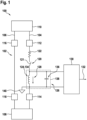
- Fig. 1 schematically shows an arc fault detection device 100 adapted for detecting an arc fault in an electric line 102, such as a series or parallel arc or an arc to ground.
- the electric line 102 may comprise one or more conductors, e.g. a phase conductor 104 and a neutral conductor 106, which connect a load 108 to an electric power source 110, e.g. a power grid or a battery.
- the arc fault detection device 100 is electrically connected to the phase conductor 104 via a first phase terminal 112 and a second phase terminal 114 and to the neutral conductor 106 via a first neutral terminal 116 and a second neutral terminal 118.
- the arc fault detection device 100 may be adapted for interrupting the electric line 102, i.e. for disconnecting the load 108 from the electric power source 110, when an arc fault is detected in at least one of the conductors 104, 106 and/or between the two conductors 104, 106 and/or between one of the two conductors 104, 106 and ground.
- the arc fault detection device 100 comprises a circuit breaker 120 with a circuit breaker switch 121 arranged in the phase conductor 104.
- the arc fault detection device 100 may comprise a bimetal 122 for protecting the electric line 102 against an overload and a magnetic actuator 124 for protecting the electric line 102 against short circuits.
- the bimetal 122 and the magnetic actuator 124 may be connected in series with the circuit breaker switch 121.
- the arc fault detection device 100 comprises a sensor 126 for detecting a current through the electric line 102, here through the phase conductor 104.
- the sensor 126 is adapted for providing a sensor signal 128, e.g. a voltage signal, in dependence of the detected current.
- a controller 130 of the arc fault detection device 100 receives the sensor signal 128 from the sensor 126 and analyzes it using a specific detection algorithm to detect an arc fault.
- the controller 130 may comprise at least a processor and a memory (not shown) to perform such an algorithm.
- the algorithm may be implemented as hardware and/or software.
- the controller 130 may be adapted for analyzing the sensor signal 128 in one or more specific frequency bands.
- the controller 130 may further be adapted for generating a trip signal 132 when an arc fault is detected.
- an auxiliary switch (not shown), e.g. an electronic switch, is operated by means of the trip signal 132, which, when operated, causes the circuit breaker switch 121 to interrupt the phase conductor 104.
- At least one of the magnetic actuator 124, the bimetal 122 and the auxiliary switch may be coupled to the circuit breaker switch 121 via a trip mechanism (not shown) of the arc fault detection device 100.
- the trip mechanism may also be operable manually by a user.
- the sensor 126 comprises an inductor 134, which is connected to the terminals of one of the conductors 104, 106.
- the inductor 134 is connected at a line side to the first phase terminal 112 (via the circuit breaker switch 121 and the bimetal 122) and at a load side to the second phase terminal 114.
- the inductor 134 may be connected to the second phase terminal 114 via the circuit breaker switch 121 and the bimetal 122.
- the inductor 134 is the magnetic actuator 124.
- the sensor 126 further comprises a capacitor 136 connected in parallel with the inductor 134.
- the inductor 134 and the capacitor 136 form a resonant circuit 138 with a resonance frequency that is adapted to a desired impedance behavior of the resonant circuit 138 over a frequency range of interest.
- the resonance frequency is adjusted such that the resonant circuit 138 has a certain impedance behavior over the frequency range of interest (see also fig. 4 and fig. 5 ).
- the resonance frequency may be adjusted based on a capacitance of the capacitor 136 and/or a resistance of a parallel-connected resistor (not shown in fig. 1 ).
- the resonance frequency may be adjusted to around 10 MHz or more.
- a sensor signal input of the controller 130 may be connected to the inductor 134 via the capacitor 136.
- the impedance behavior of the sensor 126 can be precisely adapted to the signal strength at the frequencies of interest. In that way, a very high sensitivity of the sensor 126 can be achieved.
- the cost and size constraint can be met by choosing a relatively small inductive element and then adapting its impedance accordingly.
- an additional inductive element is not necessarily required to implement the sensor 126.
- an existing component inside the arc fault detection device 100 namely the magnetic actuator 124 is used as the inductor 134.
- the magnetic actuator 124 behaves like an inductor and may be used to trip the arc fault detection device 100 in case of a short circuit.
- the magnetic actuator 124 may, for example, be used to sense an arc fault current in a frequency range from 50 Hz to 20 MHz.
- a common reference point 140 which may be arranged at a load side of the inductor 134, as shown in fig. 1 , or, alternatively, at a line side of the inductor 134, i.e., the reference point 140 may be at either of two ends of the inductor 134.
- the reference point 140 may be connected to ground.
- the resonant circuit 138 which acts as an impedance matching stage of the sensor 126
- the sensor 126 may comprise at least one of a protection stage for protecting the controller 130 against an overcurrent and/or overvoltage and a filter stage for filtering the sensor signal 128, as described in more detail below.
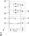
- Fig. 2 schematically shows the sensor 126 with the resonant circuit 138 and an optional protection circuit 200 for limiting a current through and/or a voltage across the sensor 126 and the controller 130.
- the protection circuit 200 interconnects the resonant circuit 138 with a sensor signal output 202 of the sensor 126, which may be connected to the sensor signal input of the controller 130 as shown in fig. 1 .
- the protection circuit 200 comprises a first pair of antiparallel Schottky diodes 204 and a second pair of antiparallel p-n junction diodes 206. Both pairs are connected in parallel with the inductor 134 and the capacitor 136.
- the antiparallel p-n junction diodes 206 may be arranged between the Schottky diodes 204 and the sensor signal output 202.
- the protection circuit 200 further comprises a first protection resistor 208 arranged between the capacitor 136 and the first pair and a second protection resistor 210 arranged between the first pair and the second pair.
- the protection resistors 208, 210 may have equal or different resistances.
- the resonant circuit 138 may comprise a resistor 212 connected in parallel with the inductor 134 and the capacitor 136.
- the resistor 212 depending on its resistance, limits the impedance of the resonant circuit 138 to a desired maximum.
- the protection circuit 200 may further comprise a protection capacitor 214, or blocking capacitor 214, connected in series with the resistor 212.
- the components of the resonant circuit 138 and the protection circuit 200 may each be connected to the reference point 140, e.g. at the load side of the inductor 134, i.e. of the magnetic actuator 124.
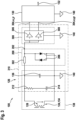
- the senor 126 may further comprise a filtering stage in the form of a filter circuit, as shown in fig. 3 .
- Fig. 3 shows the resonant circuit 138 of fig. 2 in combination with the protection circuit 200 and a filter circuit 300.
- the filter circuit 300 may be arranged between the protection circuit 200 and the sensor signal output 202 of the sensor 126.
- the protection circuit 200 here comprises only one pair of antiparallel diodes 206, which are connected in parallel with the inductor 134 and the capacitor 136.
- the diodes 206 may be p-n junction diodes.
- a transient blocking unit (TBU) 302 adapted for blocking currents higher than a specific current threshold may be arranged between the capacitor 136 and the antiparallel diodes 206.
- the transient blocking unit 302 may be seen as a non-linear active resistor. By using the transient blocking unit 302 (instead of two pairs of diodes), a more compact version of the arc fault detection device 100 can be realized.
- the filter circuit 300 generates at least one filtered signal 304 from the sensor signal 128.
- the filter circuit 300 may be a bandpass filter.
- the controller 130 may be adapted for generating the trip signal 132 from the filtered signals 304, u LF , u HF by analyzing the filtered signals 304, u LF , u HF with an arc fault detection algorithm (see above).
- the requirements for the inductor 134 may be a high inductance and a high self-resonance frequency.
- the self-resonance frequency should be above a maximum frequency of interest. In general, it is required that the inductor 134 converts the current through the electric line 102 into a sensor signal 128 above the voltage noise of the amplifiers of the arc fault detection device 100 at all frequencies of interest.
- the matching stage may increase or decrease the impedance according to the signal level of an arc fault signal.
- the matching stage may be built using capacitors and resistors.
- the protection stage ensures that peak voltages, which may appear on an inductor, cannot propagate through the electronics of the arc fault detection device 100.
- An inductor is well-suited for sensing arc fault signals over a wide frequency range, because its impedance increases with the frequency of the arc fault signal, whereas the power spectral density of the arc fault signal decreases with its frequency.
- the impedance should increase proportional to f to match the decrease in signal power of 1/ f , i.e. the decrease of the signal amplitude proportional to 1 / f .
- amplifiers already present in the arc fault detection device 100 may be used.
- the senor 126 may, at least partially, be implemented on a power supplied main board 310 of the arc fault detection device 100.
- the controller 130 may also be a component of the main board 310 or may be implemented on a separate controller board (not shown).
- Fig. 4 and fig. 5 show examples for desired impedance behaviors over a relevant frequency range of the current through the electric line 102, which, for example, may comprise frequencies up to at least 10 MHz.
- Fig. 4 shows the transfer impedance Z of the resonant circuit 138 for four different configurations of the arc fault detection device 100 in dependence of a frequency f .
- Each configuration is represented by a different impedance curve 400a to 400d, which indicate a magnitude of the transfer impedance Z.
- the maximum of each impedance curve 400a to 400d corresponds to the resonance frequency f 0 of the respective resonant circuit 138 and is limited by the resistor 212 of the respective resonant circuit 138.
- the capacitor 136 may resonate with the inductor 134 at the resonance frequency f 0 , while the resistor 212 limits the peak impedance at resonance. If not limited, the impedance could become so large that it blocks the current at the resonance frequency f 0 .
- the impedance at resonance may vary. In general, the impedance may be seen as a measure for the sensitivity of the sensor 126 at a given frequency.
- Frequencies as low as 50 Hz are very important in view of arc fault detection because they contain information about arc faults as well as about other loads connected to the installations. In this low-frequency band, it is the ohmic resistance of the windings in the inductor 134 that mostly contributes to the impedance.
- Fig. 5 exemplarily shows a desired behavior of a transfer impedance Z T of the sensor 126, represented by a first transfer impedance curve 500a in comparison to the transfer impedance Z T of a conventional arc fault detection sensor with two current transformers, represented by a second transfer impedance curve 500b. Both curves 500a, 500b indicate a magnitude of the transfer impedance Z T .
- the transfer impedance Z T is indicative of the ability of a current sensor to convert a sensed current into voltage and may be measured in the sensor 126 between the output of the filter circuit 300 and the current injected into the magnetic actuator 124.
- the transfer impedance Z T of the sensor 126 around the resonance frequency f 0 is at least four times higher than the transfer impedance Z T of the conventional sensor and rapidly decreases around the resonance peak, which makes the sensor 126 more selective in the desired frequency band.
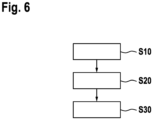
- Fig. 6 shows a flow diagram for a method for operating the arc fault detection device 100 of fig. 1 to 3 .
- step S10 the sensor signal 128, or the one or more filtered signals 304, u LF , u HF , is received at the sensor signal input of the controller 130 from the sensor signal output 202 of the sensor 126.
- step S20 the controller 130 determines from the sensor signal 128, or from the one or more filtered signals 304, u LF , u HF , whether the electric line 102 has an arc fault or not, e.g. whether there is a series arc in at least one of the conductors 104, 106, a parallel arc between the two conductors 104, 106 or an arc between one of the two conductors 104, 106 and ground.
- the detection of the arc fault may be performed by analyzing the respective signal in different frequency bands using a specific algorithm (see above).
- step S30 when the arc fault is detected, the trip signal 132 is output by the controller 130, which causes the circuit breaker switch 121 to interrupt the phase conductor 104.
Landscapes
- Physics & Mathematics (AREA)
- General Physics & Mathematics (AREA)
- Testing Of Short-Circuits, Discontinuities, Leakage, Or Incorrect Line Connections (AREA)
Claims (14)
- Dispositif (100) de détection de défaut d'arc pour détecter un défaut d'arc dans une ligne électrique (102), le dispositif (100) de détection de défaut d'arc comprenant :une première borne (112) et une deuxième borne (114) pour connecter le dispositif (100) de détection de défaut d'arc à un conducteur (104) de la ligne électrique (102) ;un capteur (126) adapté à générer un signal de capteur (128) à partir d'un courant parcourant la ligne électrique (102) ; etun contrôleur (130) adapté à détecter le défaut d'arc à partir du signal de capteur (128) ;un disjoncteur (120) adapté à interrompre la ligne électrique (102) ;le capteur (126) comprenant une inductance (134) connectée à la première borne (112) et à la deuxième borne (114) et un condensateur (136) connecté en parallèle avec l'inductance (134) ;l'inductance (134) et le condensateur (136) formant un circuit résonant (138) ayant une fréquence de résonance (f 0), la fréquence de résonance (f 0) déterminant un comportement d'impédance du circuit résonant (138) ;l'inductance (134) et une capacité du condensateur (136) étant choisies de façon à ce que le comportement d'impédance du circuit résonant (138) corresponde à un comportement d'impédance souhaité (400a, 400b, 400c, 400d ; 500a) sur une plage de fréquences pertinente du courant parcourant la ligne électrique (102) ;l'inductance (134) étant un actionneur magnétique (124) adapté à faire fonctionner le disjoncteur (120).
- Dispositif (100) de détection de défaut d'arc selon la revendication 1,
une extrémité de l'inductance (134) étant utilisée comme point de référence (140) pour le capteur (126) et/ou le contrôleur (130). - Dispositif (100) de détection de défaut d'arc selon l'une des revendications précédentes,
le capteur (126) comprenant en outre une résistance (212) connectée en parallèle avec le condensateur (136). - Dispositif (100) de détection de défaut d'arc selon l'une des revendications précédentes,le capteur (126) comprenant en outre un circuit de protection (200) adapté à limiter un courant de sortie et/ou une tension de sortie du capteur (126) ;une entrée du contrôleur (130) étant connectée, via le circuit de protection (200), au circuit résonant (138).
- Dispositif (100) de détection de défaut d'arc selon la revendication 4 associée à la revendication 3,
le circuit de protection (200) comprenant un condensateur de protection (214) connecté en série avec la résistance (212) . - Dispositif (100) de détection de défaut d'arc selon la revendication 4 ou 5,le circuit de protection (200) comprenant une unité de blocage des transitoires (302) connectée entre le condensateur (136) et le contrôleur (130) et adaptée à bloquer les courants supérieurs à un seuil de courant prédéfini ; et/oule circuit de protection (200) comprenant un suppresseur de tensions transitoires (204, 206).
- Dispositif (100) de détection de défaut d'arc selon la revendication 6,le suppresseur de tensions transitoires comprenant au moins une paire de diodes tête-bêche (204, 206) connectées en parallèle avec le condensateur (136) ; et/oule suppresseur de tensions transitoires comprenant au moins deux paires de diodes tête-bêche (204, 206) connectées en parallèle avec le condensateur (136), les diodes (204) d'une des deux paires étant des diodes Schottky.
- Dispositif (100) de détection de défaut d'arc selon la revendication 7,une résistance de protection (208, 210) étant connectée entre le condensateur (136) et l'au moins une paire de diodes tête-bêche (204, 206) ; et/ouune première résistance de protection (208) étant connectée entre le condensateur (136) et une première paire de diodes tête-bêche (204) et une deuxième résistance de protection (210) étant connectée entre la première paire de diodes tête-bêche (204) et une deuxième paire de diodes tête-bêche (206).
- Dispositif (100) de détection de défaut d'arc selon l'une des revendications précédentes,le capteur (126) comprenant en outre un circuit de filtrage (300) adapté à fournir au moins un signal filtré (304, uLF, uHF) à partir du signal de capteur (128) ;le contrôleur (130) étant adapté à détecter le défaut d'arc à partir de l'au moins un signal filtré (304, uLF, uHF)
- Dispositif (100) de détection de défaut d'arc selon la revendication 9 associée à l'une des revendications 4 à 8,
le circuit de filtrage (300) étant connecté, via le circuit de protection (200), au circuit résonant (138). - Procédé de fonctionnement d'un dispositif (100) de détection de défaut d'arc selon l'une des revendications précédentes, le procédé comprenant :la réception du signal de capteur (128) depuis le capteur (126) ;la détermination, à partir du signal de capteur (128), si la ligne électrique (102) présente ou non un défaut d'arc ;en cas de détection du défaut d'arc : la génération d'un signal de déclenchement (132) pour interrompre la ligne électrique (102).
- Procédé selon la revendication 11,
une composante basse fréquence et/ou une composante haute fréquence étant extraites/extraite du signal de capteur et étant analysées/analysée afin de déterminer si la ligne électrique présente ou non un défaut d'arc. - Programme d'ordinateur comprenant des instructions qui, lorsque le programme d'ordinateur est exécuté par un ordinateur (130), amènent l'ordinateur (130) à réaliser le procédé selon la revendication 11 ou 12.
- Support lisible par ordinateur comprenant des instructions qui, lorsqu'elles sont exécutées par un ordinateur (130), amènent l'ordinateur (130) à réaliser le procédé selon la revendication 11 ou 12.
Priority Applications (3)
| Application Number | Priority Date | Filing Date | Title |
|---|---|---|---|
| EP20198185.9A EP3974848B1 (fr) | 2020-09-24 | 2020-09-24 | Dispositif de détection de défaut d'arc comportant un capteur à large bande |
| US17/484,055 US11686758B2 (en) | 2020-09-24 | 2021-09-24 | Arc fault detection device with wideband sensor |
| CN202111120354.6A CN114252741A (zh) | 2020-09-24 | 2021-09-24 | 具有宽带传感器的电弧故障检测装置 |
Applications Claiming Priority (1)
| Application Number | Priority Date | Filing Date | Title |
|---|---|---|---|
| EP20198185.9A EP3974848B1 (fr) | 2020-09-24 | 2020-09-24 | Dispositif de détection de défaut d'arc comportant un capteur à large bande |
Publications (2)
| Publication Number | Publication Date |
|---|---|
| EP3974848A1 EP3974848A1 (fr) | 2022-03-30 |
| EP3974848B1 true EP3974848B1 (fr) | 2024-07-31 |
Family
ID=72659043
Family Applications (1)
| Application Number | Title | Priority Date | Filing Date |
|---|---|---|---|
| EP20198185.9A Active EP3974848B1 (fr) | 2020-09-24 | 2020-09-24 | Dispositif de détection de défaut d'arc comportant un capteur à large bande |
Country Status (3)
| Country | Link |
|---|---|
| US (1) | US11686758B2 (fr) |
| EP (1) | EP3974848B1 (fr) |
| CN (1) | CN114252741A (fr) |
Families Citing this family (2)
| Publication number | Priority date | Publication date | Assignee | Title |
|---|---|---|---|---|
| FR3104729B1 (fr) * | 2019-12-16 | 2022-01-14 | Schneider Electric Ind Sas | Dispositifs de détection d’un défaut d’arc électrique, appareils de protection électrique associés |
| US11784503B2 (en) * | 2021-02-22 | 2023-10-10 | Inductev Inc. | Passive arc detection and mitigation in wireless power transfer system |
Family Cites Families (47)
| Publication number | Priority date | Publication date | Assignee | Title |
|---|---|---|---|---|
| US5682101A (en) * | 1995-03-13 | 1997-10-28 | Square D Company | Arcing fault detection system |
| US6452767B1 (en) * | 1995-03-13 | 2002-09-17 | Square D Company | Arcing fault detection system for a secondary line of a current transformer |
| US6313641B1 (en) | 1995-03-13 | 2001-11-06 | Square D Company | Method and system for detecting arcing faults and testing such system |
| US5590012A (en) * | 1995-03-30 | 1996-12-31 | Siemens Energy & Automation, Inc. | Electric arc detector sensor circuit |
| US5889643A (en) | 1997-09-29 | 1999-03-30 | Eaton Corporation | Apparatus for detecting arcing faults and ground faults in multiwire branch electric power circuits |
| US5805397A (en) | 1997-09-29 | 1998-09-08 | Eaton Corporation | Arcing fault detector with multiple channel sensing and circuit breaker incorporating same |
| US6088205A (en) * | 1997-12-19 | 2000-07-11 | Leviton Manufacturing Co., Inc. | Arc fault detector with circuit interrupter |
| US6094043A (en) | 1998-04-15 | 2000-07-25 | Square D Company | ARC detection sensor utilizing discrete inductors |
| US6031699A (en) | 1998-11-23 | 2000-02-29 | Siemens Energy & Automation, Inc. | Arc fault detector apparatus, means and system |
| US6373257B1 (en) * | 1998-12-09 | 2002-04-16 | Pass & Seymour, Inc. | Arc fault circuit interrupter |
| CA2307537A1 (fr) | 1999-05-19 | 2000-11-19 | Pass & Seymour, Inc. | Disjoncteur de defaut d'arc sans alimentation c.c. |
| US8571179B2 (en) * | 1999-11-10 | 2013-10-29 | Robert Beland | Computed tomography systems |
| CA2337446A1 (fr) * | 2000-02-17 | 2001-08-17 | Bruce F. Macbeth | Disjoncteur de defaut d'arc reconnaissant les profils des salves de bruit d'arc |
| US6628487B1 (en) | 2000-04-27 | 2003-09-30 | Pass & Seymour, Inc. | Method and apparatus for detecting upstream series arc faults |
| US6987389B1 (en) | 2000-11-14 | 2006-01-17 | Pass & Seymour, Inc. | Upstream/downstream arc fault discriminator |
| US6590754B1 (en) | 2000-11-17 | 2003-07-08 | Pass & Seymour, Inc. | AFCI with false trip prevention filter |
| US6751528B1 (en) | 2000-11-27 | 2004-06-15 | General Electric Company | Residential circuit arc detection |
| DE10203163A1 (de) * | 2002-01-28 | 2003-08-07 | Tyco Electronics Amp Gmbh | Schaltungsanordnung und Verfahren zum Detektieren eines Defektes in einem Leiter |
| US7003435B2 (en) | 2002-10-03 | 2006-02-21 | Leviton Manufacturing Co., Inc. | Arc fault detector with circuit interrupter |
| WO2006068564A1 (fr) * | 2004-12-22 | 2006-06-29 | Abb Technology Ltd | Commande du flux d'energie electrique |
| US7400481B2 (en) * | 2005-12-29 | 2008-07-15 | Sensata Technologies, Inc. | Low cost arc fault detection technique |
| US7400482B2 (en) | 2006-01-17 | 2008-07-15 | Eaton Corporation | Circuit breaker and method for sensing current indirectly from bimetal voltage and determining bimetal temperature and corrected temperature dependent bimetal resistance |
| US7518840B2 (en) | 2006-02-14 | 2009-04-14 | Eaton Corporation | Electrical switching apparatus and receptacle including automatic miswiring protection |
| US7288901B1 (en) * | 2006-09-15 | 2007-10-30 | Osram Sylvania Inc. | Ballast with arc protection circuit |
| US7633727B2 (en) | 2007-02-27 | 2009-12-15 | Eaton Corporation | Arc fault circuit interrupter and series arc fault detection method using plural high frequency bands |
| CN101162851B (zh) * | 2007-09-30 | 2010-06-16 | 常熟理工学院 | 具有互校验功能的低压智能型断路器的控制器 |
| US8089737B2 (en) | 2008-12-19 | 2012-01-03 | Eaton Corporation | Arc fault circuit interrupter and method providing improved nuisance trip rejection |
| US8427794B2 (en) | 2009-06-19 | 2013-04-23 | Schneider Electric USA, Inc. | Multi-pole arc-fault circuit interrupter |
| US8218274B2 (en) * | 2009-12-15 | 2012-07-10 | Eaton Corporation | Direct current arc fault circuit interrupter, direct current arc fault detector, noise blanking circuit for a direct current arc fault circuit interrupter, and method of detecting arc faults |
| US8421473B2 (en) | 2010-05-10 | 2013-04-16 | Eaton Corporation | Apparatus and method to detect a series arc fault of an electrical circuit |
| US8542021B2 (en) | 2010-11-16 | 2013-09-24 | Schneider Electric USA, Inc. | Multi-pole arcing fault circuit breaker including a neutral current sensor |
| EP2523204B1 (fr) * | 2011-05-12 | 2019-09-04 | ABB Schweiz AG | Agencement de circuit et procédé pour l'interruption d'un flux de courant dans un accès de courant CC |
| WO2012159652A1 (fr) * | 2011-05-20 | 2012-11-29 | Sma Solar Technology Ag | Procédé et système pour détecter un défaut d'arc dans un circuit d'alimentation |
| US8599523B1 (en) | 2011-07-29 | 2013-12-03 | Leviton Manufacturing Company, Inc. | Arc fault circuit interrupter |
| CN105393326B (zh) * | 2013-03-27 | 2017-10-03 | Abb技术有限公司 | 断路布置 |
| EP2806449B8 (fr) * | 2013-05-22 | 2017-05-31 | ABB Schweiz AG | Actionneur d'une bobine pour appareil de commutation à basse et moyenne tension et dispositif de suppression de bobine de défaut d'arc comprenant ledit actionneur de bobine |
| DE102013108166B4 (de) * | 2013-07-30 | 2016-03-31 | Sma Solar Technology Ag | Vorrichtung zum erfassen von wechselstromanteilen in einem gleichstromkreis und verwendung der vorrichtung |
| US20150365003A1 (en) * | 2014-06-12 | 2015-12-17 | Laurence P. Sadwick | Power Conversion System |
| JP6749319B2 (ja) * | 2014-06-30 | 2020-09-02 | サイブレーク アーベーScibreak Ab | 電流を遮断する装置、システム及び方法 |
| US9484719B2 (en) * | 2014-07-11 | 2016-11-01 | Ming Zheng | Active-control resonant ignition system |
| WO2016205085A1 (fr) * | 2015-06-15 | 2016-12-22 | Sikorsky Aircraft Corporation | Capteur de résonance de transistor de commande de puissance |
| GB2546743B (en) * | 2016-01-26 | 2019-02-13 | Shakira Ltd | An arc fault current detector |
| CN107121618A (zh) * | 2017-03-29 | 2017-09-01 | 余晓东 | 基于自由电子热运动的热信号检测系统 |
| EP4383580A3 (fr) * | 2017-12-28 | 2024-08-21 | Solaredge Technologies Ltd. | Circuit à impédance variable |
| CN110632472A (zh) * | 2019-09-27 | 2019-12-31 | 上海工程技术大学 | 直流系统放电故障检测方法及系统 |
| CN110824320B (zh) * | 2019-12-16 | 2022-02-11 | 常熟开关制造有限公司(原常熟开关厂) | 直流电弧故障检测方法及装置 |
| US11239648B2 (en) * | 2020-03-24 | 2022-02-01 | Siemens Industry, Inc | Sensing a high frequency arc noise in an arc fault detection circuit interruption (AFCI) device |
-
2020
- 2020-09-24 EP EP20198185.9A patent/EP3974848B1/fr active Active
-
2021
- 2021-09-24 US US17/484,055 patent/US11686758B2/en active Active
- 2021-09-24 CN CN202111120354.6A patent/CN114252741A/zh active Pending
Also Published As
| Publication number | Publication date |
|---|---|
| EP3974848A1 (fr) | 2022-03-30 |
| US20220091172A1 (en) | 2022-03-24 |
| CN114252741A (zh) | 2022-03-29 |
| US11686758B2 (en) | 2023-06-27 |
Similar Documents
| Publication | Publication Date | Title |
|---|---|---|
| US9948037B2 (en) | Adapter with an electronic filtering system | |
| US11686758B2 (en) | Arc fault detection device with wideband sensor | |
| CA2321103C (fr) | Detection d'arcs de court-circuit par zones | |
| US6437955B1 (en) | Frequency-selective circuit protection arrangements | |
| US9219360B2 (en) | Safe quick disconnect leakage protector | |
| EP2293401B1 (fr) | Système de protection pour transformateurs de tension | |
| CA2141263C (fr) | Elimination de parasites electromagnetiques dans les coupe-circuit de protection contre les courts-circuits a la terre | |
| US20110110003A1 (en) | Wiring device having leakage detection function | |
| USRE42866E1 (en) | Ground fault circuit interrupter with enhanced radio frequency interference suppression | |
| SK18498A3 (en) | Disconnector for surge arrester | |
| CN210534262U (zh) | 一种谐振接地系统的大电流故障选线系统 | |
| JP6896158B2 (ja) | 漏電検出装置および漏電遮断器 | |
| EP3886282B1 (fr) | Détection d'un bruit d'arc haute fréquence d'arc dans un dispositif d'interruption de circuit de détection de défaut d'arc (afci) | |
| KR101802160B1 (ko) | 아크 검출 장치 및 아크 검출 장치를 이용한 접지 아크 검출 방법 | |
| JP4792308B2 (ja) | デジタルアンプの保護装置 | |
| EP3631926B1 (fr) | Interrupteur de circuit de défaut d'arc | |
| CN212969438U (zh) | 浪涌抑制滤波电路、电源设备及飞行器 | |
| RU2722284C1 (ru) | Устройство для предотвращения отказов силовых трансформаторов от поступления в их обмотки высокочастотных сигналов из распределительных сетей с изолированной нейтралью при возникновении в них аварийных режимов | |
| CN210142902U (zh) | 限流电路 | |
| JPH036136Y2 (fr) | ||
| CN118539379A (zh) | 一种基于有源滤波器的峰值电流保护电路 | |
| JPH04179210A (ja) | 計器用変圧器 | |
| JAMDADE | POWER SUPPLY DESIGN FOR HOME APPLIANCE WITH CONSIDERATION OF POWER QUALITY EVENTS |
Legal Events
| Date | Code | Title | Description |
|---|---|---|---|
| PUAI | Public reference made under article 153(3) epc to a published international application that has entered the european phase |
Free format text: ORIGINAL CODE: 0009012 |
|
| STAA | Information on the status of an ep patent application or granted ep patent |
Free format text: STATUS: THE APPLICATION HAS BEEN PUBLISHED |
|
| AK | Designated contracting states |
Kind code of ref document: A1 Designated state(s): AL AT BE BG CH CY CZ DE DK EE ES FI FR GB GR HR HU IE IS IT LI LT LU LV MC MK MT NL NO PL PT RO RS SE SI SK SM TR |
|
| STAA | Information on the status of an ep patent application or granted ep patent |
Free format text: STATUS: REQUEST FOR EXAMINATION WAS MADE |
|
| 17P | Request for examination filed |
Effective date: 20220919 |
|
| RBV | Designated contracting states (corrected) |
Designated state(s): AL AT BE BG CH CY CZ DE DK EE ES FI FR GB GR HR HU IE IS IT LI LT LU LV MC MK MT NL NO PL PT RO RS SE SI SK SM TR |
|
| GRAP | Despatch of communication of intention to grant a patent |
Free format text: ORIGINAL CODE: EPIDOSNIGR1 |
|
| STAA | Information on the status of an ep patent application or granted ep patent |
Free format text: STATUS: GRANT OF PATENT IS INTENDED |
|
| INTG | Intention to grant announced |
Effective date: 20240301 |
|
| GRAS | Grant fee paid |
Free format text: ORIGINAL CODE: EPIDOSNIGR3 |
|
| GRAA | (expected) grant |
Free format text: ORIGINAL CODE: 0009210 |
|
| STAA | Information on the status of an ep patent application or granted ep patent |
Free format text: STATUS: THE PATENT HAS BEEN GRANTED |
|
| AK | Designated contracting states |
Kind code of ref document: B1 Designated state(s): AL AT BE BG CH CY CZ DE DK EE ES FI FR GB GR HR HU IE IS IT LI LT LU LV MC MK MT NL NO PL PT RO RS SE SI SK SM TR |
|
| REG | Reference to a national code |
Ref country code: CH Ref legal event code: EP Ref country code: GB Ref legal event code: FG4D |
|
| REG | Reference to a national code |
Ref country code: DE Ref legal event code: R096 Ref document number: 602020034765 Country of ref document: DE |
|
| REG | Reference to a national code |
Ref country code: IE Ref legal event code: FG4D |