EP3974742B1 - Heat pump water heater and air supply structure thereof - Google Patents
Heat pump water heater and air supply structure thereof Download PDFInfo
- Publication number
- EP3974742B1 EP3974742B1 EP20215242.7A EP20215242A EP3974742B1 EP 3974742 B1 EP3974742 B1 EP 3974742B1 EP 20215242 A EP20215242 A EP 20215242A EP 3974742 B1 EP3974742 B1 EP 3974742B1
- Authority
- EP
- European Patent Office
- Prior art keywords
- air
- housing
- cavity
- fan
- heat pump
- Prior art date
- Legal status (The legal status is an assumption and is not a legal conclusion. Google has not performed a legal analysis and makes no representation as to the accuracy of the status listed.)
- Active
Links
Images


Classifications
-
- F—MECHANICAL ENGINEERING; LIGHTING; HEATING; WEAPONS; BLASTING
- F24—HEATING; RANGES; VENTILATING
- F24H—FLUID HEATERS, e.g. WATER OR AIR HEATERS, HAVING HEAT-GENERATING MEANS, e.g. HEAT PUMPS, IN GENERAL
- F24H4/00—Fluid heaters characterised by the use of heat pumps
- F24H4/02—Water heaters
-
- F—MECHANICAL ENGINEERING; LIGHTING; HEATING; WEAPONS; BLASTING
- F24—HEATING; RANGES; VENTILATING
- F24H—FLUID HEATERS, e.g. WATER OR AIR HEATERS, HAVING HEAT-GENERATING MEANS, e.g. HEAT PUMPS, IN GENERAL
- F24H4/00—Fluid heaters characterised by the use of heat pumps
- F24H4/02—Water heaters
- F24H4/04—Storage heaters
-
- F—MECHANICAL ENGINEERING; LIGHTING; HEATING; WEAPONS; BLASTING
- F24—HEATING; RANGES; VENTILATING
- F24H—FLUID HEATERS, e.g. WATER OR AIR HEATERS, HAVING HEAT-GENERATING MEANS, e.g. HEAT PUMPS, IN GENERAL
- F24H9/00—Details
- F24H9/0005—Details for water heaters
-
- F—MECHANICAL ENGINEERING; LIGHTING; HEATING; WEAPONS; BLASTING
- F24—HEATING; RANGES; VENTILATING
- F24H—FLUID HEATERS, e.g. WATER OR AIR HEATERS, HAVING HEAT-GENERATING MEANS, e.g. HEAT PUMPS, IN GENERAL
- F24H9/00—Details
- F24H9/0005—Details for water heaters
- F24H9/001—Guiding means
Definitions
- CN 111380216 A discloses an air duct structure and belongs to the technical field of water heaters.
- the air supply structure comprises a volute, an air guiding housing and an exhaust ring.
- the air outlet end of the volute communicates with the air inlet end of the air guiding housing; an air blocking piece is arranged on the edge of the periphery of the volute.
- the air outlet end of the air guiding housing communicates with an inner arc surface of the exhaust ring.
- the periphery of the exhaust ring is provided with air guiding fins which are arc-shaped and are all bent to the same side.
- the fan can be fixed on the casing and can be guaranteed to drive the impeller to rotate normally in a steady state.
- the clamping groove is formed on an inner wall of the first cavity or an inner wall of the second cavity.
- the clamping groove is formed by combining a first groove body formed on an inner wall of the first cavity and a second groove body formed on an inner wall of the second cavity.
- the arrangement form of the clamping groove can be selected according to the actual situation for fixing the fan.
- the air guiding portion is set in the form of an air guiding chamber with an opening, which increases the air guiding amount and improves the efficiency of air gathering.
- the first housing is provided with a first connecting portion
- the second housing is provided with a second connecting portion.
- the first connecting portion is connected with the second connecting portion for connecting the first housing with the second housing.
- the first connecting portion is in inserted connection or clamped connection with the second connecting portion for connecting the first housing with the second housing.
- the connecting portions positioned on the two housings connect the two housings together to form the casing, thus ensuring the integration of the casing, preventing the air inside the air cavity from escaping from the joint to affect the tightness and stability of the air supply structure.
- the clamping groove is formed on the inner wall of the first cavity 13 or the inner wall of the second cavity 23.
- the clamping groove is formed by combining a first groove body 15 formed on the inner wall of the first cavity 13 and a second groove body 25 formed on the inner wall of the second cavity 23.
- the first groove body 15 is of insertion groove structure formed on the inner wall of the first cavity 13
- the second groove body 25 is of insertion groove structure formed on the inner wall of the second cavity 23.
- An opening, for clamping the fan, of the first groove body 15 is consistent with an open end of the first cavity 13 in orientation
- an opening, for clamping the fan, of the second groove body 25 is consistent with an open end of the second cavity 23 in orientation.
- the clamping groove is preferably a sunken cavity in one side wall of the air cavity, and the air cavity is communicated with the clamping groove.
- the first air hole 16 and the second air hole 26 are respectively notches located at an open end of the first cavity 13 and the second cavity 23.
- a shape of the air inlet 6 can be designed as desired, and can be circular, square, oval, and the like.
- the casing 12 is provided with an air guiding structure for guiding air into the air cavity through the air inlet 6.
- the air guiding structure can be an air guiding chamber 7 with an opening.
- the air guiding chamber 7 is formed on the first housing 1 or the second housing 2.
- the air guiding chamber 7 is formed by combining a first air concave part 17 formed on the first housing 1 and a second air concave part 27 formed on the second housing 2.
- the air guiding structure is arranged outside a side wall, provided with the air inlet 6, of the casing 12, and is located around the air inlet 6, ensuring that air discharged from the heat exchanger 14 of the heat pump water heater can enter the air inlet 6 as much as possible.
- the casing 12 is integrally connected with the air guiding structure.
- the air guiding chamber 7 can be a chamber formed by a protruding plate structure on a side wall of the first housing 1 and/or the second housing 2, or a chamber formed by a plate structure extending from an adjacent wall of the side wall towards the air inlet direction.
- the first housing 1 is provided with a first connecting portion 18, and the second housing 2 is provided with a second connecting portion 28.
- the first connecting portion 18 is connected with the second connecting portion 28 to connect the first housing 1 with the second housing 2.
- the first connecting portion 18 is in inserted connection or clamped connection with the second connecting portion 28 to connect the first housing 1 with the second housing 2.
- the structure of the connecting portion has a variety of forms, including a buckle structure, a hook structure, a screw structure, an inserting structure, and the like.
- the first housing 1 and the second housing 2 are separately formed by foaming a thermoplastic foamed material.
- the thermoplastic foamed material includes at least one of a plastic foamed material and a rubber foamed material.
- the thermoplastic foamed material may be an expanded polypropylene material (an EPP material for short) or an expanded polystyrene material (an EPS material for short) or the like.
- the first housing 1 and second housing 2 can be formed integrally by directly foaming plastic foamed materials according to the design graphics of the first housing 1 and the second housing 2 respectively, without connection by connecting parts.
- Installation method first clamping the clamping portion 101 of the fan 10 into the second groove body 25 of the second housing 2 correspondingly, placing the working portion of the fan 10 into the second cavity 23, then enabling the first groove body 15 of the first housing 1 to sleeve the clamping portion 101 from an upper part, then buckling all portions of the first housing 1 with all portions of the second housing 2 in a one-to-one matching manner correspondingly, and finally connecting the first housing 1 with the second housing 2 via the connecting portions to form a complete casing 12.
- an air supply structure of a heat pump water heater includes a fan 10 and a casing 12.
- the casing 12 includes a first housing 1 and a second housing 2.
- the first housing 1 is connected to the second housing 2 in an up-down manner so that the first housing 1 is arranged at the upper part of the second housing 2 when the first housing 1 is to be connected with the second housing 2.
- One side wall of an open end of the first cavity 13 is provided with a first air hole 16 of a semi-circular notch structure.
- One side wall of an open end of the second cavity 23 is provided with a second air hole 26 of a semi-circular notch structure. The first air hole 16 and the second air hole 26 are combined to form a circular air inlet 6.
- the clamping groove is composed of two groove bodies formed on two cavities together.
- the stability of the casing 12 is improved to facilitate support of the fan 10 by the casing 12 to provide a more secure connection between the fan 10 and the casing 12.
- the air guiding chamber 7 is formed by combining two air concave parts formed on the first housing 1 and the second housing 2 to draw air into the air cavity as much as possible, and the air guiding effect of the casing 12 is improved to facilitate air gathering.
- an air supply structure of a heat pump water heater includes a casing 12.
- the casing 12 includes a first housing 1 and a second housing 2 that are formed by directly foaming an expanded polypropylene material (an EPP material for short).
- the shape of an outer wall of the casing 12 is matched with the shape of an inner wall of a shell for covering the heat pump system, for preventing a situation that perfect buckling cannot be achieved due to mismatch in the shape of the outer wall of the casing 12 when the shell is used for covering the heat pump system.
- the processing process is complicated by the need to combine and connect the various parts during the production and processing of the casing, and there is also a risk of loosening and disjointing the connection relationship between the various parts of the casing, thus reducing the stability of the casing.
- heat insulation cotton is also required to be pasted to an inner side wall of the casing for heat insulation and noise reduction.
- the heat insulation cotton is less effective in heat insulation and noise reduction effects and is prone to fall off during installation.
- the assembly process among various parts is complicated and less efficient, thus affecting the entire production cycle.
Landscapes
- Engineering & Computer Science (AREA)
- Physics & Mathematics (AREA)
- Thermal Sciences (AREA)
- Chemical & Material Sciences (AREA)
- Combustion & Propulsion (AREA)
- Mechanical Engineering (AREA)
- General Engineering & Computer Science (AREA)
- Structures Of Non-Positive Displacement Pumps (AREA)
Description
- The present invention belongs to the field of heat pump water heaters, and in particular relates an air supply structure of a heat pump water heater comprising the features of the preamble portion of
claim 1 and further to a heat pump water heater provided with the air supply structure. - An air supply structure of a heat pump water heater in the prior art is complex, includes a fan, a volute and associated supporting and connecting parts, and is cumbersome in installation process and low in installation efficiency. For the installation of the fan and the volute, corresponding supporting structures need to be designed, and connection and fastening are achieved by means of screws. The installation process is complicated and the structural parts are large in number, thus increasing installation difficulty and reducing the overall reliability.
- In addition, some types of heat pump water heaters have higher requirements on air supply structures, for example, integrated air guiding type air-energy heat pump water heaters. An integrated air guiding type air-energy heat pump water heater is typically installed in the indoor environment. During working of the water heater, an air duct discharges cold air out of a room, and the cold air is prevented from being making contact with indoor air for causing a drop in indoor temperature and affecting the user's comfort. Thus the integrated air guiding type air-energy heat pump water heater requires the air duct to have good sealing and heat insulation effects, to only exchange heat with outdoor air without affecting the temperature of indoor air during working. At the same time, the integrated air guiding type air-energy heat pump water heater also requires the air duct to have good sound insulation and noise reduction effects as the integrated air guiding type air-energy heat pump water heater is placed indoors.
- However, in an existing air duct, heat insulation cotton is generally pasted to the inner side of a shell for heat insulation and noise reduction, the sealability is poor, the heat insulation cotton is prone to fall off in the pasting process, heat exchange with indoor air is prone to occur, product quality is not easily guaranteed, and user's comfort is impacted. The overall production process has higher requirements on manual installation techniques, thus reducing production speed and affecting the overall production efficiency.
-
CN 111380216 A discloses an air duct structure and belongs to the technical field of water heaters. The air supply structure comprises a volute, an air guiding housing and an exhaust ring. The air outlet end of the volute communicates with the air inlet end of the air guiding housing; an air blocking piece is arranged on the edge of the periphery of the volute. The air outlet end of the air guiding housing communicates with an inner arc surface of the exhaust ring. The periphery of the exhaust ring is provided with air guiding fins which are arc-shaped and are all bent to the same side. - The air duct structure in the above solution comprises a volute structure, which is complicated in both structure and production and assembly processes. And the fan is arranged inside the volute, and connecting parts such as screws need to be used for fixing during assembling of the fan and the volute, so that the installation process is complicated. The air duct cannot play the role of heat preservation and heat insulation effects well.
-
EP 2 354 709 A2claim 1. More specifically,EP 2 354 709 A2 - Another air supply structure of a heat pump is known from
DE 20 2016 003 295 U . The air supply structure includes a housing for an air space of the heat pump. The housing comprises at least one upper part and one lower part. At least one fan is arranged in the air space. The housing of the air space unit is designed in several parts and comprises a slide-like insert and an air duct, the slide-like insert and the air duct being air tightly connected to the upper and lower parts of the housing are connected and fixed by means of detents. -
- The technical problem to be solved by the present invention is to provide an air supply structure of a heat pump water heater, which is simple in structure, convenient to install, and has good heat insulation and noise reduction effects.
- This technical problem is solved by a heat pump water heater comprising the features of
claim 1 and further to a heat pump water heater according toclaim 11. Advantageous embodiments are indicated in further claims. - By adopting the above solution, the casing of the air supply structure is composed of two housings, compared with the integrated housing in the prior art, the two housings can be installed in steps, thus reducing the installation difficulty and simplifying the installation process. In addition, the fan is clamped in the chamber, instead of achieving the connection between the fan and the casing using screws or connectors in the prior art, thus simplifying the installation structure, reducing the number of installation parts, and reducing the production costs.
- Further, the chamber includes a clamping groove for clamping the fan and an air cavity for forming an air path for the fan and provided with an air inlet and an air outlet. The clamping groove and the air inlet are opposite arranged in an axial direction of the fan.
- By adopting the above solution, the chamber can both guarantee normal operation of the fan and provide support for the fan, thus improving the stability of the fan while not impeding operation of the fan. A supporting portion used for supporting the fan is set in the form of a clamping groove, and instead of fixing of the fan and the casing using connecting parts such as screws in the prior art, thus the installation speed is accelerated, the number of installation parts is reduced, and the production cost is reduced.
- Further, the fan includes a working portion and a clamping portion. The working portion includes a motor and an impeller. And the clamping portion is embedded in the clamping groove, and the motor is mounted on the clamping portion.
- By adopting the above solution, the fan can be fixed on the casing and can be guaranteed to drive the impeller to rotate normally in a steady state.
- In a preferred embodiment, the clamping groove is formed on an inner wall of the first cavity or an inner wall of the second cavity. Alternatively, the clamping groove is formed by combining a first groove body formed on an inner wall of the first cavity and a second groove body formed on an inner wall of the second cavity.
- By adopting the above solution, the arrangement form of the clamping groove can be selected according to the actual situation for fixing the fan.
- In another preferred embodiment, the air inlet is formed on the first housing or the second housing. Or, the air inlet is formed by combining a first air hole formed on the first housing and a second air hole formed on the second housing; the first air hole is communicated with the first cavity, and the second air hole is communicated with the second cavity.
- In yet another preferred embodiment, the casing is provided with an air guiding structure for guiding air into the air cavity through the air inlet. Preferably, the air guiding structure is an air guiding chamber with an opening.
- By adopting the above solution, due to the arrangement of the air guiding structure, air can be gathered and enters the air cavity through the air inlet, and the air guiding portion is set in the form of an air guiding chamber with an opening, which increases the air guiding amount and improves the efficiency of air gathering.
- In yet another preferred embodiment, the air guiding chamber is formed on the first housing or the second housing. Alternatively, the air guiding chamber is formed by combining a first air concave part formed on the first housing and a second air concave part formed on the second housing.
- In yet another preferred embodiment, the first housing is provided with a first connecting portion, the second housing is provided with a second connecting portion. The first connecting portion is connected with the second connecting portion for connecting the first housing with the second housing. Preferably, the first connecting portion is in inserted connection or clamped connection with the second connecting portion for connecting the first housing with the second housing.
- By adopting the above solution, the connecting portions positioned on the two housings connect the two housings together to form the casing, thus ensuring the integration of the casing, preventing the air inside the air cavity from escaping from the joint to affect the tightness and stability of the air supply structure.
- In yet another preferred embodiment, the first housing and the second housing are separately formed by foaming a thermoplastic foamed material. Preferably, the thermoplastic foamed material includes at least one of a plastic foamed material and a rubber foamed material.
- By adopting the above solution, the first housing and the second housing are formed by foaming the thermoplastic foamed material, thus avoiding complex assembly between parts, simplifying the assembly process of the casing, improving the efficiency of batch production, and omitting associated connecting parts for connection.
- On the other hand, foamed plastic and foamed rubber have good heat insulation and noise reduction effects, can effectively separate the inside environment from the outside environment of the air cavity, can prevent heat exchange between the air inside the air cavity and the indoor air to cause a drop in the temperature of the indoor environment, and can prevent the adverse effect caused to the user by the noise generated by the fan. In addition, the casing made of the foam material is light in weight, installation and transportation are facilitated, and the weight of the whole machine is also effectively reduced. The disadvantages that in the prior art, heat insulation cotton is used to be pasted to the inner wall of the casing for heat insulation and noise reduction, the effect is poor, the heat insulation cotton is prone to fall off in the pasting process, the product quality cannot be easily guaranteed, and the like are ameliorated.
- The present invention has the following beneficial effects compared with the prior art.
- 1. The casing of the air supply structure is divided into the first housing and the second housing, in addition, the two housings are connected by the connecting portions to form a complete casing structure after combination, thus facilitating the assembly of the casing and the fan while ensuring integration of the air cavity, the fan and the casing can be quickly connected, the operation is simple and convenient and fast, and the installation process of the air supply structure is simplified.
- 2. The chamber is arranged in the casing, the fan is clamped in the chamber, and the clamping groove of the chamber provides support for the fan instead of connection between the casing and the fan using connecting parts such as bolts in the prior art, so that the air supply structure is simplified, the speed of installation is increased, the efficiency of installation is improved, the number of installation parts is reduced and the cost of production is reduced.
- 3. The casing may be formed by foaming the thermoplastic foamed material, thus avoiding complex assembly between parts, simplifying the assembly process of the casing, improving the efficiency of batch production, and omitting associated connecting parts for connection. In addition, heat exchange between the air in the air cavity and the indoor air is prevented, the heat insulation and noise reduction effects of the casing are improved, the weight of the casing is reduced, the disadvantages that in the prior art, heat insulation cotton is used to be pasted to the inner wall of the casing for heat insulation and noise reduction, the effect is poor, the heat insulation cotton is prone to fall off in the pasting process, the product quality cannot be easily guaranteed, and the like are ameliorated.
- Ways for carrying out the invention will be described in further detail below in conjunction with the accompanying drawings.
- The accompanying drawings serve to provide a further understanding but do not constitute an undue definition. The accompanying drawings in the following description are merely some embodiments, and for those of ordinary skill in the art, other accompanying drawings can also be obtained from these accompanying drawings without paying creative labor.
- In the drawings:
-
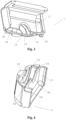
Fig. 1 is an assembled schematic diagram of an air supply structure for a heat pump water heater according to an embodiment of the present invention; -
Fig. 2 is a structural schematic diagram of a casing according to an embodiment of the present invention; -
Fig. 3 is a structural schematic diagram of a first housing according to an embodiment of the present invention; -
Fig. 4 is a structural schematic diagram of a second housing according to an embodiment of the present invention; -
Fig. 5 is a structural schematic diagram of a fan according to an embodiment of the present invention; -
Fig. 6 is an installation structural schematic diagram of an air supply structure for a heat pump water heater according to an embodiment of the present invention. - In the drawings: 1, first housing; 11, fixing seat; 12, casing; 13, first cavity; 14, heat exchanger; 15, first groove body; 16, first air hole; 17, first air concave part; 18, first connecting portion; 2, second housing; 23, second cavity; 25, second groove body; 26, second air hole; 27, second air concave part; 28, second connecting portion; 6, air inlet; 7, air guiding chamber; 9, air outlet; 10, fan; 101, clamping portion; 102, impeller; 1021, fan cover.
- In order to make the objects, technical solutions and advantages of embodiments of the present disclosure clearer, technical solutions in embodiments will now be clearly and completely described in conjunction with the accompanying drawings in embodiments of the present disclosure, the following embodiments are illustrative of the present disclosure but not intended to limit the scope of the present disclosure.
- In the description of the disclosure, it should be noted that, the terms "upper", "inner", "outer", and the like indicate orientations or positional relationships based on those shown in the drawings, are merely for ease of description of the disclosure and simplifying the description, and are not intended to indicate or imply that the devices or elements referred to must have a particular orientation, be constructed and operate in a particular orientation, and therefore cannot be interpreted as limiting the present disclosure.
- Throughout the description of the present disclosure, it should be noted that, unless otherwise clearly specified and limited, the terms "connected" and "connection" should be broadly understood, e.g., it can be fixed connection or detachable connection or integral connection, can also be mechanical connection or electrical connection, and can also be direct connection or indirect connection through a medium. The specific meaning of the above terms in the present disclosure can be understood by those of ordinary skill in the art in accordance with specific conditions.
- As shown in
Figs. 1 to 6 , a heat pump water heater of the present disclosure includes aheat exchanger 14, a fixingseat 11 and an air supply structure. The air supply structure includes afan 10 and acasing 12. Thecasing 12 includes afirst housing 1 and asecond housing 2. Thefirst housing 1 is provided with afirst cavity 13, thesecond housing 2 is provided with asecond cavity 23, and thefirst cavity 13 and thesecond cavity 23 cooperatively define a chamber. Thefirst housing 1 cooperates with thesecond housing 2 to clamp thefan 10 in the chamber. The chamber includes a clamping groove and an air cavity. The clamping groove is used for clamping thefan 10; and the air cavity is used for forming an air path for thefan 10. The air cavity is provided with an air inlet 6 and anair outlet 9; the clamping groove and the air inlet 6 are opposite arranged in an axial direction of thefan 10. - The clamping groove is formed on the inner wall of the
first cavity 13 or the inner wall of thesecond cavity 23. Or, the clamping groove is formed by combining afirst groove body 15 formed on the inner wall of thefirst cavity 13 and asecond groove body 25 formed on the inner wall of thesecond cavity 23. Thefirst groove body 15 is of insertion groove structure formed on the inner wall of thefirst cavity 13, and thesecond groove body 25 is of insertion groove structure formed on the inner wall of thesecond cavity 23. An opening, for clamping the fan, of thefirst groove body 15 is consistent with an open end of thefirst cavity 13 in orientation, and an opening, for clamping the fan, of thesecond groove body 25 is consistent with an open end of thesecond cavity 23 in orientation. - The air inlet 6 can be formed only on the
first housing 1 or thesecond housing 2. The air inlet 6 can also be formed by combining afirst air hole 16 formed on thefirst housing 1 and asecond air hole 26 formed on thesecond housing 2. Thefirst air hole 16 is communicated with thefirst cavity 13, and thesecond air hole 26 is communicated with thesecond cavity 23. - The clamping groove is preferably a sunken cavity in one side wall of the air cavity, and the air cavity is communicated with the clamping groove.
- In the case of the air inlet 6 being formed by combining the two housings, the
first air hole 16 and thesecond air hole 26 are respectively notches located at an open end of thefirst cavity 13 and thesecond cavity 23. In addition, a shape of the air inlet 6 can be designed as desired, and can be circular, square, oval, and the like. - The
fan 10 includes a working portion including and a clampingportion 101. The working portion includes a motor and animpeller 102. The clampingportion 101 is embedded in the clamping groove. The motor is mounted on the clampingportion 101. One end of the motor is fixed by the clampingportion 101, and then the motor drives theimpeller 102 to rotate. Theimpeller 102 is arranged at a port of the air inlet 6 for extracting air at the air inlet 6. Preferably, theimpeller 102 is located between the clampingportion 101 and the air inlet 6. - The
casing 12 is provided with an air guiding structure for guiding air into the air cavity through the air inlet 6. The air guiding structure can be anair guiding chamber 7 with an opening. Theair guiding chamber 7 is formed on thefirst housing 1 or thesecond housing 2. Alternatively, theair guiding chamber 7 is formed by combining a first airconcave part 17 formed on thefirst housing 1 and a second airconcave part 27 formed on thesecond housing 2. The air guiding structure is arranged outside a side wall, provided with the air inlet 6, of thecasing 12, and is located around the air inlet 6, ensuring that air discharged from theheat exchanger 14 of the heat pump water heater can enter the air inlet 6 as much as possible. - Preferably, the
casing 12 is integrally connected with the air guiding structure. - The
air guiding chamber 7 can be a chamber formed by a protruding plate structure on a side wall of thefirst housing 1 and/or thesecond housing 2, or a chamber formed by a plate structure extending from an adjacent wall of the side wall towards the air inlet direction. - The
first housing 1 is provided with a first connectingportion 18, and thesecond housing 2 is provided with a second connectingportion 28. The first connectingportion 18 is connected with the second connectingportion 28 to connect thefirst housing 1 with thesecond housing 2. Preferably, the first connectingportion 18 is in inserted connection or clamped connection with the second connectingportion 28 to connect thefirst housing 1 with thesecond housing 2. The structure of the connecting portion has a variety of forms, including a buckle structure, a hook structure, a screw structure, an inserting structure, and the like. - The
first housing 1 and thesecond housing 2 are separately formed by foaming a thermoplastic foamed material. The thermoplastic foamed material includes at least one of a plastic foamed material and a rubber foamed material. - The thermoplastic foamed material may be an expanded polypropylene material (an EPP material for short) or an expanded polystyrene material (an EPS material for short) or the like.
- When the
casing 12 is processed, thefirst housing 1 andsecond housing 2 can be formed integrally by directly foaming plastic foamed materials according to the design graphics of thefirst housing 1 and thesecond housing 2 respectively, without connection by connecting parts. - Working principle: air discharged from the
heat exchanger 14 enters the air cavity through the air inlet 6 under the air guiding action of theair guiding chamber 7, and theimpeller 102 of thefan 10 rotates to accelerate flowing of the air in the air cavity so that the air is eventually discharged from theair outlet 9 arranged on the first housing 1 (seeFig. 6 ). - Installation method: first clamping the clamping
portion 101 of thefan 10 into thesecond groove body 25 of thesecond housing 2 correspondingly, placing the working portion of thefan 10 into thesecond cavity 23, then enabling thefirst groove body 15 of thefirst housing 1 to sleeve the clampingportion 101 from an upper part, then buckling all portions of thefirst housing 1 with all portions of thesecond housing 2 in a one-to-one matching manner correspondingly, and finally connecting thefirst housing 1 with thesecond housing 2 via the connecting portions to form acomplete casing 12. - As one implementation mode, as shown in
Figs. 1 to 5 , an air supply structure of a heat pump water heater includes afan 10 and acasing 12. Thecasing 12 includes afirst housing 1 and asecond housing 2. Thefirst housing 1 is connected to thesecond housing 2 in an up-down manner so that thefirst housing 1 is arranged at the upper part of thesecond housing 2 when thefirst housing 1 is to be connected with thesecond housing 2. - As a preferred solution, as shown in
Figs. 2 to 5 , thefirst housing 1 is provided with afirst cavity 13, and thesecond housing 2 is provided with asecond cavity 23. Thefirst cavity 13 and thesecond cavity 23 are combined to form a chamber of which a cross section is rectangular. The chamber includes an air cavity and a clamping groove formed on an inner wall of the air cavity by recessing. The clamping groove is formed by combining afirst groove body 15 formed on the inner wall of thefirst cavity 13 and asecond groove body 25 formed on the inner wall of thesecond cavity 23. - One side wall of an open end of the
first cavity 13 is provided with afirst air hole 16 of a semi-circular notch structure. One side wall of an open end of thesecond cavity 23 is provided with asecond air hole 26 of a semi-circular notch structure. Thefirst air hole 16 and thesecond air hole 26 are combined to form a circular air inlet 6. - The
fan 10 includes a clampingportion 101 and a working portion connected to the clampingportion 101. The working portion includes a motor and animpeller 102, and the motor is mounted on the clampingportion 101. The working portion is placed in the air cavity, and the clampingportion 101 is clamped into the clamping groove for supporting thefan 10. - Further, end faces of open ends of the cavities of the
first housing 1 and thesecond housing 2 are provided with concave chambers respectively. The concave chambers are combined to form a wiring hole. The clampingportion 101 is also provided with a wiring hole. Wire is connected to the motor of thefan 10 through the wiring holes. - Further, a side wall, provided with the
first air hole 16, of thefirst housing 1 is provided with a first airconcave part 17. The first airconcave part 17 is of an open structure, and an opening faces the open end of thefirst cavity 13 and theheat exchanger 14. The first airconcave part 17 encloses the side wall on its three sides. A side wall, provided with thesecond air hole 26, of thesecond housing 2 is provided with a second airconcave part 27. The second airconcave part 27 is of an open structure, and an opening faces the open end of thesecond cavity 23 and theheat exchanger 14. The second airconcave part 27 encloses the side wall on its three sides. Two air concave parts cooperate to be buckled onto theheat exchanger 14 of the heat pump water heater for guiding air discharged from theheat exchanger 14 into the air cavity from the air inlet 6 (seeFig. 6 ). - By adopting the above solution, the clamping groove is composed of two groove bodies formed on two cavities together. The stability of the
casing 12 is improved to facilitate support of thefan 10 by thecasing 12 to provide a more secure connection between thefan 10 and thecasing 12. In addition, theair guiding chamber 7 is formed by combining two air concave parts formed on thefirst housing 1 and thesecond housing 2 to draw air into the air cavity as much as possible, and the air guiding effect of thecasing 12 is improved to facilitate air gathering. - As one implementation mode, as shown in
Figs. 1 to 5 , an air supply structure of a heat pump water heater includes afan 10 and acasing 12. Thefan 10 includes a clampingportion 101 and a working portion, and the working portion includes animpeller 102 and a motor. The motor is arranged in the middle of the clampingportion 101 via a positioning device, and theimpeller 102 is connected to the motor and rotates under a driving action of the motor. Afan cover 1021 is arranged on blades of theimpeller 102, sleeves the peripheries of the blades and rotates along with the blades. Theimpeller 102 rotates under the driving of the motor to extract air through the air inlet 6. The flowing path of the air is from the air inlet 6 to the blades through thefan cover 1021, and into the air cavity through gaps between the blades under rotation of the blades. Since thefan cover 1021 rotates with the blades, thefan cover 1021 is arranged at a port, facing the air cavity, of the air inlet 6 for receiving air from the air inlet 6 when thefan 10 is installed. An outer diameter of thefan cover 1021 is smaller than a diameter of the air inlet 6. Thefan cover 1021 is preferably of a circular structure. - As a preferred solution, the clamping
portion 101 is a fan fixing plate arranged at an end far away from thefan cover 1021, and the fan fixing plate is polygonal in shape. The clamping groove is of a groove structure in the air cavity, and communicates with the air cavity, and the groove structure is matched with the fan fixing plate in shape to clamp the fan fixing plate into the chamber of thecasing 12. - In addition, an
air outlet 9 is formed in thefirst housing 1, is opposite to thefirst cavity 13. Theair outlet 9 faces a radial direction of thefan 10, and communicates with the air cavity for discharging the air in the air cavity out of the air supply structure. - Further, the air supply structure is also provided with an air discharge pipeline in matched connection with the
air outlet 9 for further discharging the air at theair outlet 9 out of the chamber. - By adopting the above solution, the
fan cover 1021 is arranged at the air inlet 6 and has a certain air gathering action to assist the blades in extracting air from the air inlet 6 to a certain extent. And in addition, thecircular fan cover 1021 can reduce the resistance of the air flow and reduce the energy consumption. - As one embodiment, as shown in
Figs. 1 to 5 , an air supply structure of a heat pump water heater includes afan 10 and acasing 12. Thecasing 12 includes afirst housing 1 and asecond housing 2. Thefirst housing 1 is provided with a first connectingportion 18, and thesecond housing 2 is provided with a second connectingportion 28. Multiple groups of the first connecting portion and the second connecting portion are arranged on thefirst housing 1 and thesecond housing 2. - As a preferred solution, four groups of the first connecting portion and the second connecting portion are arranged. The first connecting
portions 18 and the second connectingportions 28 are arranged at a connected end of thefirst housing 1 and a connected end of thesecond housing 2 respectively. The first connectingportions 18 and the second connectingportions 28 are connected by means of insertion. The connecting portions include bumps and grooves. The first connectingportions 18 are respectively a groove structure formed in an end surface of an open end of thefirst cavity 13, a bump structure arranged on the first airconcave part 17 at two sides of thefirst cavity 13, and a bump structure arranged on the middle part of an outer wall of thefirst housing 1. The second connectingportions 28 are matched with the first connectingportions 18 in position and are respectively a bump structure arranged on an end surface of an open end of thesecond cavity 23, a groove structure formed in the second airconcave part 27 at two sides of thesecond cavity 23, and a groove structure formed in the middle part of an outer wall of thesecond housing 2. - Further, sealing glue is coated to the end surface of the open end of the
first cavity 13 and the end surface of the open end of thesecond cavity 23 respectively. Thefirst housing 1 is buckled to thesecond housing 2 to form thecomplete casing 12, which further prevent the air in the air cavity from escaping from a junction of the open end of thefirst cavity 13 and the open end of thesecond cavity 23 to affect the sealability of thecasing 12. - In the above solution, arranging four groups of connecting portions here is merely an implementation mode. The present disclosure does not limit the number of the connecting portions which are arranged at four positions, namely the left, middle and right of the
first housing 1 and thesecond housing 2 and the end faces of the open ends of the two cavities respectively, for ensuring that the two connecting portions can firmly connect thefirst housing 1 and thesecond housing 2 to form acomplete casing 12, and ensuring the stability and tightness of thecasing 12. - In addition, the first connecting
portions 18 and the second connectingportions 28 are set in the structural form of bumps and grooves, so that when thefirst housing 1 is connected to thesecond housing 2, it is only necessary to correspondingly insert the bumps into the matched grooves, thereby allowing convenient disassembly while ensuring the connecting effect of thefirst housing 1 and thesecond housing 2. - As an implementation mode, as shown in
Fig. 6 , an installation structure of an air supply structure of a heat pump water heater includes the air supply structure, aheat exchanger 14 and a fixingseat 11 for fixing the air supply structure. The air supply structure includes acasing 12, and thecasing 12 includes asecond housing 2 arranged on the fixingseat 11. And thesecond housing 2 is preferably connected to the fixingseat 11 by clamping and inserting. A bottom wall of thesecond housing 2 is provided with a connecting part for being connected with the fixingseat 11. The connecting part is preferably of a convex-concave matched connection structure of bump and groove. - As an implementation mode, as shown in
Figs. 1 to 5 , an air supply structure of a heat pump water heater includes acasing 12. Thecasing 12 includes afirst housing 1 and asecond housing 2 that are formed by directly foaming an expanded polypropylene material (an EPP material for short). The shape of an outer wall of thecasing 12 is matched with the shape of an inner wall of a shell for covering the heat pump system, for preventing a situation that perfect buckling cannot be achieved due to mismatch in the shape of the outer wall of thecasing 12 when the shell is used for covering the heat pump system. - The processing process is complicated by the need to combine and connect the various parts during the production and processing of the casing, and there is also a risk of loosening and disjointing the connection relationship between the various parts of the casing, thus reducing the stability of the casing. On the other hand, since some types of heat pump water heaters have higher requirements on the heat insulation and noise reduction functions of the casing of the air supply structure, after the casing is connected and processed by using connecting parts, heat insulation cotton is also required to be pasted to an inner side wall of the casing for heat insulation and noise reduction. The heat insulation cotton is less effective in heat insulation and noise reduction effects and is prone to fall off during installation. And the assembly process among various parts is complicated and less efficient, thus affecting the entire production cycle.
- By adopting the above solution, the
first housing 1 and thesecond housing 2 of thecasing 12 are formed by directly foaming an expanded polypropylene material, thus avoiding complex assembly of parts, simplifying the assembly process of the air supply structure, improving the efficiency of batch production, omitting associated connecting parts for connection, and simplifying the production process of the air supply structure. - On the other hand, the expanded polypropylene material (an EPP material for short) has good heat insulation and noise reduction effects, can effectively separate an inside from an outside of the air cavity, can prevent heat exchange between the air inside the air cavity and the indoor air to cause a drop in the temperature of the indoor environment, and can prevent the adverse effect caused to the user by the noise generated by the
fan 10. In addition, the air supply structure is light in weight, installation and transportation are facilitated, and the weight of the whole machine is also effectively reduced. The disadvantages that in the prior art, heat insulation cotton is used to be pasted to the inner wall of thecasing 12 for heat insulation and noise reduction, the effect is poor, the heat insulation cotton is prone to fall off in the pasting process, the product quality cannot be easily guaranteed, and the like are ameliorated. - The above embodiments are only preferred embodiments of the disclosure, and are not intended to limit the disclosure in any form. Although the disclosure has been disclosed above in terms of preferred embodiments, the embodiments are not used for limiting the disclosure. Any person familiar with this patent, without departing from the scope of the technical solution of the disclosure, can make some changes to the proposed technical contents or modify the embodiments to equivalent embodiments of equivalent variations, the implementation solutions in the above embodiments can be further combined or substituted, any simple changes, and modifications made to the above embodiments without departing from the content of the claims.
Claims (11)
- An air supply structure of a heat pump water heater, comprising a fan (10) and a casing (12), wherein the casing (12) comprises,a first housing (1), provided with a first cavity (13); anda second housing (2), provided with a second cavity (23);the casing (12) is internally provided with a chamber formed by the first cavity (13) and the second cavity (23);the first housing (1) is matched with the second housing (2) ;the chamber comprises,a clamping groove, for clamping the fan (10); andan air cavity, for forming an air path for the fan (10), and provided with an air inlet (6) and an air outlet (9);the clamping groove and the air inlet (6) are opposite arranged in an axial direction of the fan (10);the fan (10) comprises,a working portion, comprising a motor and an impeller (102); anda clamping portion (101), embedded in the clamping groove;wherein the motor is mounted on the clamping portion (101);characterized in thatthe first housing (1) is matched with the second housing (2) to clamp the fan (10) in the chamber;the air outlet (9) faces a radial direction of the fan (10);the clamping portion (101) is a fan fixing plate polygonal in shape and the clamping groove is matched with the fan fixing plate in shape to clamp the fan fixing plate into the chamber of the casing (12); andthe impeller (102) is located between the clamping portion (101) and the air inlet (6).
- The air supply structure of the heat pump water heater according to claim 1, wherein the clamping groove is formed on an inner wall of the first cavity (13) or an inner wall of the second cavity (23);
or,
the clamping groove is formed by combining a first groove body (15) formed on an inner wall of the first cavity and a second groove body (25) formed on an inner wall of the second cavity. - The air supply structure of the heat pump water heater according to claim 1 or 2, wherein the air inlet (6) is formed on the first housing (1) or the second housing (2);
or,the air inlet (6) is formed by combining a first air hole (16) formed on the first housing and a second air hole (26) formed on the second housing;the first air hole (16) is communicated with the first cavity (13), and the second air hole (26) is communicated with the second cavity (23). - The air supply structure of the heat pump water heater according to any one of claims 1 to 3, wherein the casing (12) is provided with an air guiding structure for guiding air into the air cavity through the air inlet (6).
- The air supply structure of the heat pump water heater according to claim 4, the air guiding structure is an air guiding chamber with an opening.
- The air supply structure of the heat pump water heater according to claim 4 or 5, wherein the air guiding chamber is formed in the first housing or the second housing;
or,
the air guiding chamber is formed by combining a first air concave part (17) formed in the first housing (1) and a second air concave part (27) formed in the second housing (2). - The air supply structure of the heat pump water heater according to any one of claims 1 to 6, wherein the first housing (1) is provided with a first connecting portion (18), the second housing (2) is provided with a second connecting portion (28), and
the first connecting portion (18) is connected with the second connecting portions (28) for connecting the first housing with the second housing. - The air supply structure of the heat pump water heater according to claim 7, the first connecting portion (18) is in inserted connection or in clamped connection with the second connecting portions (28) for connecting the first housing with the second housing.
- The air supply structure of the heat pump water heater according to any one of claims 1 to 8, wherein the first housing (1) and the second housing (2) are separately formed by foaming a thermoplastic foamed material.
- The air supply structure of the heat pump water heater according to claim 9, the thermoplastic foamed material comprises at least one of a plastic foamed material and a rubber foamed material.
- A heat pump water heater, provided with the air supply structure according to any one of claims 1 to 10.
Applications Claiming Priority (1)
| Application Number | Priority Date | Filing Date | Title |
|---|---|---|---|
| CN202011011360.3A CN112833544B (en) | 2020-09-23 | 2020-09-23 | A heat pump water heater and its air supply structure |
Publications (2)
| Publication Number | Publication Date |
|---|---|
| EP3974742A1 EP3974742A1 (en) | 2022-03-30 |
| EP3974742B1 true EP3974742B1 (en) | 2024-07-17 |
Family
ID=73855642
Family Applications (1)
| Application Number | Title | Priority Date | Filing Date |
|---|---|---|---|
| EP20215242.7A Active EP3974742B1 (en) | 2020-09-23 | 2020-12-17 | Heat pump water heater and air supply structure thereof |
Country Status (3)
| Country | Link |
|---|---|
| EP (1) | EP3974742B1 (en) |
| CN (1) | CN112833544B (en) |
| ES (1) | ES2985704T3 (en) |
Families Citing this family (5)
| Publication number | Priority date | Publication date | Assignee | Title |
|---|---|---|---|---|
| CN115750444B (en) * | 2022-12-26 | 2026-01-13 | 三捷电器(佛山)有限公司 | Fan structure and installation method |
| WO2025025366A1 (en) * | 2023-07-31 | 2025-02-06 | 广东美的制冷设备有限公司 | Head unit assembly and heat pump water heater |
| CN116989479B (en) * | 2023-08-31 | 2026-02-17 | 浙江美的热能技术有限公司 | Machine head assembly and heat pump water heater |
| CN116989482B (en) * | 2023-08-31 | 2025-12-19 | 浙江美的热能技术有限公司 | Machine head assembly and heat pump water heater |
| IT202300019899A1 (en) * | 2023-09-27 | 2025-03-27 | Ariston Spa | EXTERNAL UNIT FOR A HEAT PUMP AND HEAT PUMP |
Family Cites Families (16)
| Publication number | Priority date | Publication date | Assignee | Title |
|---|---|---|---|---|
| JP2000111117A (en) * | 1998-10-08 | 2000-04-18 | Fuji Kogyo Kk | Range hood fan with blower installed |
| DE202010001244U1 (en) * | 2010-01-21 | 2011-05-26 | Stiebel Eltron GmbH & Co. KG, 37603 | Air / water heat pump for outdoor installation |
| DE102013102093A1 (en) * | 2013-03-04 | 2014-09-04 | Viessmann Werke Gmbh & Co Kg | Heat technical device |
| CN204610387U (en) * | 2015-04-29 | 2015-09-02 | 广东美的制冷设备有限公司 | The fixed structure of fan and air conditioner |
| EP3128252A1 (en) * | 2015-08-07 | 2017-02-08 | Vaillant GmbH | Heat pump system |
| CN205717525U (en) * | 2016-03-28 | 2016-11-23 | 广东美的制冷设备有限公司 | Indoor apparatus of air conditioner and air-conditioner |
| DE202016003295U1 (en) * | 2016-05-30 | 2016-06-22 | Kermi Gmbh | Housing for the air space of a heat pump installed in an interior |
| CN108344176A (en) * | 2017-01-24 | 2018-07-31 | 青岛海尔新能源电器有限公司 | A kind of Teat pump boiler |
| CN109425021B (en) * | 2017-08-18 | 2023-07-28 | 广东美的制冷设备有限公司 | Air conditioner indoor unit and air conditioner |
| CN207674678U (en) * | 2017-12-20 | 2018-07-31 | 北京环都拓普空调有限公司 | A kind of fresh air purified scavenger with integrated formed structure |
| CN208059215U (en) * | 2018-04-18 | 2018-11-06 | 广东美的制冷设备有限公司 | fan assembly and air conditioner |
| PT111104A (en) * | 2018-08-14 | 2020-02-14 | Bosch Termotecnologia Sa | HEAT PUMP AND FAN FOR A HEAT PUMP |
| CN210220225U (en) * | 2019-01-03 | 2020-03-31 | 广东纽恩泰新能源科技发展有限公司 | A kind of upper and lower air outlet heat exchange circulation fan |
| CN110056962A (en) * | 2019-05-10 | 2019-07-26 | 青岛海尔空调器有限总公司 | Wall-hanging indoor unit of air conditioner |
| CN210602259U (en) * | 2019-09-27 | 2020-05-22 | 任丘市九合新能源科技有限公司 | Energy-saving variable frequency air heater convenient to adjust |
| CN210951871U (en) * | 2019-10-24 | 2020-07-07 | 广州西奥多科技有限公司 | Wall-mounted heat pump water heater |
-
2020
- 2020-09-23 CN CN202011011360.3A patent/CN112833544B/en active Active
- 2020-12-17 EP EP20215242.7A patent/EP3974742B1/en active Active
- 2020-12-17 ES ES20215242T patent/ES2985704T3/en active Active
Also Published As
| Publication number | Publication date |
|---|---|
| CN112833544A (en) | 2021-05-25 |
| CN112833544B (en) | 2022-12-13 |
| EP3974742A1 (en) | 2022-03-30 |
| ES2985704T3 (en) | 2024-11-07 |
Similar Documents
| Publication | Publication Date | Title |
|---|---|---|
| EP3974742A1 (en) | Heat pump water heater and air supply structure thereof | |
| US7191613B2 (en) | Turbo fan and air conditioner having the same applied thereto | |
| CN112918218A (en) | Air conditioning device and automobile | |
| CN108375117A (en) | Floor air conditioner | |
| CN109724159B (en) | Heat exchange component of air conditioner indoor unit and air conditioner indoor unit | |
| CN105179273B (en) | Air conditioning equipment | |
| CN217814030U (en) | Fan assembly and gas warmer | |
| CN216346702U (en) | Air conditioner | |
| CN205825236U (en) | Wall-hanging air conditioner indoor unit and air-conditioner | |
| CN112361455A (en) | Indoor unit and air conditioner with same | |
| CN215490329U (en) | Air source heat pump water heater | |
| CN213955442U (en) | Indoor unit and air conditioner with same | |
| CN214984714U (en) | Air conditioning device and automobile | |
| CN109631155B (en) | Air conditioner | |
| CN209558553U (en) | The heat exchanger components and air conditioner indoor unit of air conditioner indoor unit | |
| KR100389394B1 (en) | Turbofan assembling structure for air conditioner | |
| CN209944534U (en) | Air conditioner | |
| CN223709775U (en) | Air conditioner | |
| KR20020019157A (en) | Turbofan for air conditioner | |
| KR20020019160A (en) | Turbofan for air conditioner | |
| CN112128128A (en) | ceiling fan | |
| CN221003212U (en) | Handheld fan and air nozzle for the handheld fan | |
| CN221279564U (en) | Air conditioner indoor unit | |
| CN223621819U (en) | Fan subassembly and heat pump equipment | |
| CN113124499A (en) | Window type air conditioner |
Legal Events
| Date | Code | Title | Description |
|---|---|---|---|
| PUAI | Public reference made under article 153(3) epc to a published international application that has entered the european phase |
Free format text: ORIGINAL CODE: 0009012 |
|
| STAA | Information on the status of an ep patent application or granted ep patent |
Free format text: STATUS: THE APPLICATION HAS BEEN PUBLISHED |
|
| AK | Designated contracting states |
Kind code of ref document: A1 Designated state(s): AL AT BE BG CH CY CZ DE DK EE ES FI FR GB GR HR HU IE IS IT LI LT LU LV MC MK MT NL NO PL PT RO RS SE SI SK SM TR |
|
| STAA | Information on the status of an ep patent application or granted ep patent |
Free format text: STATUS: REQUEST FOR EXAMINATION WAS MADE |
|
| 17P | Request for examination filed |
Effective date: 20220610 |
|
| RBV | Designated contracting states (corrected) |
Designated state(s): AL AT BE BG CH CY CZ DE DK EE ES FI FR GB GR HR HU IE IS IT LI LT LU LV MC MK MT NL NO PL PT RO RS SE SI SK SM TR |
|
| GRAP | Despatch of communication of intention to grant a patent |
Free format text: ORIGINAL CODE: EPIDOSNIGR1 |
|
| STAA | Information on the status of an ep patent application or granted ep patent |
Free format text: STATUS: GRANT OF PATENT IS INTENDED |
|
| INTG | Intention to grant announced |
Effective date: 20240306 |
|
| GRAS | Grant fee paid |
Free format text: ORIGINAL CODE: EPIDOSNIGR3 |
|
| GRAA | (expected) grant |
Free format text: ORIGINAL CODE: 0009210 |
|
| STAA | Information on the status of an ep patent application or granted ep patent |
Free format text: STATUS: THE PATENT HAS BEEN GRANTED |
|
| AK | Designated contracting states |
Kind code of ref document: B1 Designated state(s): AL AT BE BG CH CY CZ DE DK EE ES FI FR GB GR HR HU IE IS IT LI LT LU LV MC MK MT NL NO PL PT RO RS SE SI SK SM TR |
|
| REG | Reference to a national code |
Ref country code: CH Ref legal event code: EP |
|
| REG | Reference to a national code |
Ref country code: DE Ref legal event code: R096 Ref document number: 602020034052 Country of ref document: DE |
|
| REG | Reference to a national code |
Ref country code: IE Ref legal event code: FG4D |
|
| REG | Reference to a national code |
Ref country code: ES Ref legal event code: FG2A Ref document number: 2985704 Country of ref document: ES Kind code of ref document: T3 Effective date: 20241107 |
|
| REG | Reference to a national code |
Ref country code: LT Ref legal event code: MG9D |
|
| REG | Reference to a national code |
Ref country code: NL Ref legal event code: MP Effective date: 20240717 |
|
| PG25 | Lapsed in a contracting state [announced via postgrant information from national office to epo] |
Ref country code: PT Free format text: LAPSE BECAUSE OF FAILURE TO SUBMIT A TRANSLATION OF THE DESCRIPTION OR TO PAY THE FEE WITHIN THE PRESCRIBED TIME-LIMIT Effective date: 20241118 |
|
| REG | Reference to a national code |
Ref country code: AT Ref legal event code: MK05 Ref document number: 1704488 Country of ref document: AT Kind code of ref document: T Effective date: 20240717 |
|
| PG25 | Lapsed in a contracting state [announced via postgrant information from national office to epo] |
Ref country code: NL Free format text: LAPSE BECAUSE OF FAILURE TO SUBMIT A TRANSLATION OF THE DESCRIPTION OR TO PAY THE FEE WITHIN THE PRESCRIBED TIME-LIMIT Effective date: 20240717 |
|
| PG25 | Lapsed in a contracting state [announced via postgrant information from national office to epo] |
Ref country code: PT Free format text: LAPSE BECAUSE OF FAILURE TO SUBMIT A TRANSLATION OF THE DESCRIPTION OR TO PAY THE FEE WITHIN THE PRESCRIBED TIME-LIMIT Effective date: 20241118 Ref country code: NL Free format text: LAPSE BECAUSE OF FAILURE TO SUBMIT A TRANSLATION OF THE DESCRIPTION OR TO PAY THE FEE WITHIN THE PRESCRIBED TIME-LIMIT Effective date: 20240717 |
|
| PG25 | Lapsed in a contracting state [announced via postgrant information from national office to epo] |
Ref country code: NO Free format text: LAPSE BECAUSE OF FAILURE TO SUBMIT A TRANSLATION OF THE DESCRIPTION OR TO PAY THE FEE WITHIN THE PRESCRIBED TIME-LIMIT Effective date: 20241017 |
|
| PG25 | Lapsed in a contracting state [announced via postgrant information from national office to epo] |
Ref country code: FI Free format text: LAPSE BECAUSE OF FAILURE TO SUBMIT A TRANSLATION OF THE DESCRIPTION OR TO PAY THE FEE WITHIN THE PRESCRIBED TIME-LIMIT Effective date: 20240717 Ref country code: GR Free format text: LAPSE BECAUSE OF FAILURE TO SUBMIT A TRANSLATION OF THE DESCRIPTION OR TO PAY THE FEE WITHIN THE PRESCRIBED TIME-LIMIT Effective date: 20241018 Ref country code: PL Free format text: LAPSE BECAUSE OF FAILURE TO SUBMIT A TRANSLATION OF THE DESCRIPTION OR TO PAY THE FEE WITHIN THE PRESCRIBED TIME-LIMIT Effective date: 20240717 |
|
| PG25 | Lapsed in a contracting state [announced via postgrant information from national office to epo] |
Ref country code: BG Free format text: LAPSE BECAUSE OF FAILURE TO SUBMIT A TRANSLATION OF THE DESCRIPTION OR TO PAY THE FEE WITHIN THE PRESCRIBED TIME-LIMIT Effective date: 20240717 |
|
| PG25 | Lapsed in a contracting state [announced via postgrant information from national office to epo] |
Ref country code: LV Free format text: LAPSE BECAUSE OF FAILURE TO SUBMIT A TRANSLATION OF THE DESCRIPTION OR TO PAY THE FEE WITHIN THE PRESCRIBED TIME-LIMIT Effective date: 20240717 |
|
| PG25 | Lapsed in a contracting state [announced via postgrant information from national office to epo] |
Ref country code: IS Free format text: LAPSE BECAUSE OF FAILURE TO SUBMIT A TRANSLATION OF THE DESCRIPTION OR TO PAY THE FEE WITHIN THE PRESCRIBED TIME-LIMIT Effective date: 20241117 Ref country code: AT Free format text: LAPSE BECAUSE OF FAILURE TO SUBMIT A TRANSLATION OF THE DESCRIPTION OR TO PAY THE FEE WITHIN THE PRESCRIBED TIME-LIMIT Effective date: 20240717 |
|
| PG25 | Lapsed in a contracting state [announced via postgrant information from national office to epo] |
Ref country code: HR Free format text: LAPSE BECAUSE OF FAILURE TO SUBMIT A TRANSLATION OF THE DESCRIPTION OR TO PAY THE FEE WITHIN THE PRESCRIBED TIME-LIMIT Effective date: 20240717 |
|
| PG25 | Lapsed in a contracting state [announced via postgrant information from national office to epo] |
Ref country code: RS Free format text: LAPSE BECAUSE OF FAILURE TO SUBMIT A TRANSLATION OF THE DESCRIPTION OR TO PAY THE FEE WITHIN THE PRESCRIBED TIME-LIMIT Effective date: 20241017 |
|
| PG25 | Lapsed in a contracting state [announced via postgrant information from national office to epo] |
Ref country code: RS Free format text: LAPSE BECAUSE OF FAILURE TO SUBMIT A TRANSLATION OF THE DESCRIPTION OR TO PAY THE FEE WITHIN THE PRESCRIBED TIME-LIMIT Effective date: 20241017 Ref country code: PL Free format text: LAPSE BECAUSE OF FAILURE TO SUBMIT A TRANSLATION OF THE DESCRIPTION OR TO PAY THE FEE WITHIN THE PRESCRIBED TIME-LIMIT Effective date: 20240717 Ref country code: NO Free format text: LAPSE BECAUSE OF FAILURE TO SUBMIT A TRANSLATION OF THE DESCRIPTION OR TO PAY THE FEE WITHIN THE PRESCRIBED TIME-LIMIT Effective date: 20241017 Ref country code: LV Free format text: LAPSE BECAUSE OF FAILURE TO SUBMIT A TRANSLATION OF THE DESCRIPTION OR TO PAY THE FEE WITHIN THE PRESCRIBED TIME-LIMIT Effective date: 20240717 Ref country code: IS Free format text: LAPSE BECAUSE OF FAILURE TO SUBMIT A TRANSLATION OF THE DESCRIPTION OR TO PAY THE FEE WITHIN THE PRESCRIBED TIME-LIMIT Effective date: 20241117 Ref country code: HR Free format text: LAPSE BECAUSE OF FAILURE TO SUBMIT A TRANSLATION OF THE DESCRIPTION OR TO PAY THE FEE WITHIN THE PRESCRIBED TIME-LIMIT Effective date: 20240717 Ref country code: GR Free format text: LAPSE BECAUSE OF FAILURE TO SUBMIT A TRANSLATION OF THE DESCRIPTION OR TO PAY THE FEE WITHIN THE PRESCRIBED TIME-LIMIT Effective date: 20241018 Ref country code: FI Free format text: LAPSE BECAUSE OF FAILURE TO SUBMIT A TRANSLATION OF THE DESCRIPTION OR TO PAY THE FEE WITHIN THE PRESCRIBED TIME-LIMIT Effective date: 20240717 Ref country code: BG Free format text: LAPSE BECAUSE OF FAILURE TO SUBMIT A TRANSLATION OF THE DESCRIPTION OR TO PAY THE FEE WITHIN THE PRESCRIBED TIME-LIMIT Effective date: 20240717 Ref country code: AT Free format text: LAPSE BECAUSE OF FAILURE TO SUBMIT A TRANSLATION OF THE DESCRIPTION OR TO PAY THE FEE WITHIN THE PRESCRIBED TIME-LIMIT Effective date: 20240717 |
|
| PG25 | Lapsed in a contracting state [announced via postgrant information from national office to epo] |
Ref country code: RO Free format text: LAPSE BECAUSE OF FAILURE TO SUBMIT A TRANSLATION OF THE DESCRIPTION OR TO PAY THE FEE WITHIN THE PRESCRIBED TIME-LIMIT Effective date: 20240717 Ref country code: SM Free format text: LAPSE BECAUSE OF FAILURE TO SUBMIT A TRANSLATION OF THE DESCRIPTION OR TO PAY THE FEE WITHIN THE PRESCRIBED TIME-LIMIT Effective date: 20240717 Ref country code: DK Free format text: LAPSE BECAUSE OF FAILURE TO SUBMIT A TRANSLATION OF THE DESCRIPTION OR TO PAY THE FEE WITHIN THE PRESCRIBED TIME-LIMIT Effective date: 20240717 |
|
| REG | Reference to a national code |
Ref country code: DE Ref legal event code: R097 Ref document number: 602020034052 Country of ref document: DE |
|
| PG25 | Lapsed in a contracting state [announced via postgrant information from national office to epo] |
Ref country code: EE Free format text: LAPSE BECAUSE OF FAILURE TO SUBMIT A TRANSLATION OF THE DESCRIPTION OR TO PAY THE FEE WITHIN THE PRESCRIBED TIME-LIMIT Effective date: 20240717 |
|
| PG25 | Lapsed in a contracting state [announced via postgrant information from national office to epo] |
Ref country code: CZ Free format text: LAPSE BECAUSE OF FAILURE TO SUBMIT A TRANSLATION OF THE DESCRIPTION OR TO PAY THE FEE WITHIN THE PRESCRIBED TIME-LIMIT Effective date: 20240717 |
|
| PG25 | Lapsed in a contracting state [announced via postgrant information from national office to epo] |
Ref country code: SK Free format text: LAPSE BECAUSE OF FAILURE TO SUBMIT A TRANSLATION OF THE DESCRIPTION OR TO PAY THE FEE WITHIN THE PRESCRIBED TIME-LIMIT Effective date: 20240717 |
|
| PLBE | No opposition filed within time limit |
Free format text: ORIGINAL CODE: 0009261 |
|
| STAA | Information on the status of an ep patent application or granted ep patent |
Free format text: STATUS: NO OPPOSITION FILED WITHIN TIME LIMIT |
|
| 26N | No opposition filed |
Effective date: 20250422 |
|
| REG | Reference to a national code |
Ref country code: DE Ref legal event code: R119 Ref document number: 602020034052 Country of ref document: DE |
|
| PG25 | Lapsed in a contracting state [announced via postgrant information from national office to epo] |
Ref country code: MC Free format text: LAPSE BECAUSE OF FAILURE TO SUBMIT A TRANSLATION OF THE DESCRIPTION OR TO PAY THE FEE WITHIN THE PRESCRIBED TIME-LIMIT Effective date: 20240717 |
|
| REG | Reference to a national code |
Ref country code: CH Ref legal event code: PL |
|
| PG25 | Lapsed in a contracting state [announced via postgrant information from national office to epo] |
Ref country code: LU Free format text: LAPSE BECAUSE OF NON-PAYMENT OF DUE FEES Effective date: 20241217 |
|
| PG25 | Lapsed in a contracting state [announced via postgrant information from national office to epo] |
Ref country code: SE Free format text: LAPSE BECAUSE OF FAILURE TO SUBMIT A TRANSLATION OF THE DESCRIPTION OR TO PAY THE FEE WITHIN THE PRESCRIBED TIME-LIMIT Effective date: 20240717 |
|
| REG | Reference to a national code |
Ref country code: BE Ref legal event code: MM Effective date: 20241231 |
|
| PG25 | Lapsed in a contracting state [announced via postgrant information from national office to epo] |
Ref country code: DE Free format text: LAPSE BECAUSE OF NON-PAYMENT OF DUE FEES Effective date: 20250701 |
|
| PG25 | Lapsed in a contracting state [announced via postgrant information from national office to epo] |
Ref country code: BE Free format text: LAPSE BECAUSE OF NON-PAYMENT OF DUE FEES Effective date: 20241231 |
|
| PG25 | Lapsed in a contracting state [announced via postgrant information from national office to epo] |
Ref country code: CH Free format text: LAPSE BECAUSE OF NON-PAYMENT OF DUE FEES Effective date: 20241231 |
|
| PG25 | Lapsed in a contracting state [announced via postgrant information from national office to epo] |
Ref country code: IE Free format text: LAPSE BECAUSE OF NON-PAYMENT OF DUE FEES Effective date: 20241217 |
|
| PGFP | Annual fee paid to national office [announced via postgrant information from national office to epo] |
Ref country code: GB Payment date: 20251229 Year of fee payment: 6 |
|
| PG25 | Lapsed in a contracting state [announced via postgrant information from national office to epo] |
Ref country code: IT Free format text: LAPSE BECAUSE OF NON-PAYMENT OF DUE FEES Effective date: 20241217 |
|
| PGFP | Annual fee paid to national office [announced via postgrant information from national office to epo] |
Ref country code: FR Payment date: 20251222 Year of fee payment: 6 |
|
| PGFP | Annual fee paid to national office [announced via postgrant information from national office to epo] |
Ref country code: ES Payment date: 20260119 Year of fee payment: 6 |
|
| PG25 | Lapsed in a contracting state [announced via postgrant information from national office to epo] |
Ref country code: IT Free format text: LAPSE BECAUSE OF NON-PAYMENT OF DUE FEES Effective date: 20241217 |
|
| PGFP | Annual fee paid to national office [announced via postgrant information from national office to epo] |
Ref country code: IT Payment date: 20251231 Year of fee payment: 6 |
|
| PGRI | Patent reinstated in contracting state [announced from national office to epo] |
Ref country code: IT Effective date: 20250430 |
|
| PG25 | Lapsed in a contracting state [announced via postgrant information from national office to epo] |
Ref country code: CY Free format text: LAPSE BECAUSE OF FAILURE TO SUBMIT A TRANSLATION OF THE DESCRIPTION OR TO PAY THE FEE WITHIN THE PRESCRIBED TIME-LIMIT Effective date: 20240717 |
|
| PG25 | Lapsed in a contracting state [announced via postgrant information from national office to epo] |
Ref country code: TR Free format text: LAPSE BECAUSE OF FAILURE TO SUBMIT A TRANSLATION OF THE DESCRIPTION OR TO PAY THE FEE WITHIN THE PRESCRIBED TIME-LIMIT Effective date: 20240717 |
|
| PG25 | Lapsed in a contracting state [announced via postgrant information from national office to epo] |
Ref country code: HU Free format text: LAPSE BECAUSE OF FAILURE TO SUBMIT A TRANSLATION OF THE DESCRIPTION OR TO PAY THE FEE WITHIN THE PRESCRIBED TIME-LIMIT; INVALID AB INITIO Effective date: 20201217 |
|
| PG25 | Lapsed in a contracting state [announced via postgrant information from national office to epo] |
Ref country code: SI Free format text: LAPSE BECAUSE OF FAILURE TO SUBMIT A TRANSLATION OF THE DESCRIPTION OR TO PAY THE FEE WITHIN THE PRESCRIBED TIME-LIMIT Effective date: 20240717 |
|
| PG25 | Lapsed in a contracting state [announced via postgrant information from national office to epo] |
Ref country code: LT Free format text: LAPSE BECAUSE OF FAILURE TO SUBMIT A TRANSLATION OF THE DESCRIPTION OR TO PAY THE FEE WITHIN THE PRESCRIBED TIME-LIMIT Effective date: 20240717 |