EP3974703A1 - Magnetic attraction conductive track, adapter, electrical device and electrical system - Google Patents
Magnetic attraction conductive track, adapter, electrical device and electrical system Download PDFInfo
- Publication number
- EP3974703A1 EP3974703A1 EP20885644.3A EP20885644A EP3974703A1 EP 3974703 A1 EP3974703 A1 EP 3974703A1 EP 20885644 A EP20885644 A EP 20885644A EP 3974703 A1 EP3974703 A1 EP 3974703A1
- Authority
- EP
- European Patent Office
- Prior art keywords
- conductive
- magnetically
- adsorbed
- wall
- adapter
- Prior art date
- Legal status (The legal status is an assumption and is not a legal conclusion. Google has not performed a legal analysis and makes no representation as to the accuracy of the status listed.)
- Pending
Links
Images















Classifications
-
- F—MECHANICAL ENGINEERING; LIGHTING; HEATING; WEAPONS; BLASTING
- F21—LIGHTING
- F21S—NON-PORTABLE LIGHTING DEVICES; SYSTEMS THEREOF; VEHICLE LIGHTING DEVICES SPECIALLY ADAPTED FOR VEHICLE EXTERIORS
- F21S4/00—Lighting devices or systems using a string or strip of light sources
- F21S4/20—Lighting devices or systems using a string or strip of light sources with light sources held by or within elongate supports
- F21S4/28—Lighting devices or systems using a string or strip of light sources with light sources held by or within elongate supports rigid, e.g. LED bars
-
- F—MECHANICAL ENGINEERING; LIGHTING; HEATING; WEAPONS; BLASTING
- F21—LIGHTING
- F21S—NON-PORTABLE LIGHTING DEVICES; SYSTEMS THEREOF; VEHICLE LIGHTING DEVICES SPECIALLY ADAPTED FOR VEHICLE EXTERIORS
- F21S8/00—Lighting devices intended for fixed installation
- F21S8/04—Lighting devices intended for fixed installation intended only for mounting on a ceiling or the like overhead structures
-
- F—MECHANICAL ENGINEERING; LIGHTING; HEATING; WEAPONS; BLASTING
- F21—LIGHTING
- F21V—FUNCTIONAL FEATURES OR DETAILS OF LIGHTING DEVICES OR SYSTEMS THEREOF; STRUCTURAL COMBINATIONS OF LIGHTING DEVICES WITH OTHER ARTICLES, NOT OTHERWISE PROVIDED FOR
- F21V21/00—Supporting, suspending, or attaching arrangements for lighting devices; Hand grips
- F21V21/14—Adjustable mountings
- F21V21/30—Pivoted housings or frames
-
- F—MECHANICAL ENGINEERING; LIGHTING; HEATING; WEAPONS; BLASTING
- F21—LIGHTING
- F21V—FUNCTIONAL FEATURES OR DETAILS OF LIGHTING DEVICES OR SYSTEMS THEREOF; STRUCTURAL COMBINATIONS OF LIGHTING DEVICES WITH OTHER ARTICLES, NOT OTHERWISE PROVIDED FOR
- F21V21/00—Supporting, suspending, or attaching arrangements for lighting devices; Hand grips
- F21V21/34—Supporting elements displaceable along a guiding element
- F21V21/35—Supporting elements displaceable along a guiding element with direct electrical contact between the supporting element and electric conductors running along the guiding element
-
- H—ELECTRICITY
- H01—ELECTRIC ELEMENTS
- H01R—ELECTRICALLY-CONDUCTIVE CONNECTIONS; STRUCTURAL ASSOCIATIONS OF A PLURALITY OF MUTUALLY-INSULATED ELECTRICAL CONNECTING ELEMENTS; COUPLING DEVICES; CURRENT COLLECTORS
- H01R13/00—Details of coupling devices of the kinds covered by groups H01R12/70 or H01R24/00 - H01R33/00
- H01R13/62—Means for facilitating engagement or disengagement of coupling parts or for holding them in engagement
- H01R13/6205—Two-part coupling devices held in engagement by a magnet
-
- H—ELECTRICITY
- H01—ELECTRIC ELEMENTS
- H01R—ELECTRICALLY-CONDUCTIVE CONNECTIONS; STRUCTURAL ASSOCIATIONS OF A PLURALITY OF MUTUALLY-INSULATED ELECTRICAL CONNECTING ELEMENTS; COUPLING DEVICES; CURRENT COLLECTORS
- H01R25/00—Coupling parts adapted for simultaneous co-operation with two or more identical counterparts, e.g. for distributing energy to two or more circuits
- H01R25/14—Rails or bus-bars constructed so that the counterparts can be connected thereto at any point along their length
-
- H—ELECTRICITY
- H01—ELECTRIC ELEMENTS
- H01R—ELECTRICALLY-CONDUCTIVE CONNECTIONS; STRUCTURAL ASSOCIATIONS OF A PLURALITY OF MUTUALLY-INSULATED ELECTRICAL CONNECTING ELEMENTS; COUPLING DEVICES; CURRENT COLLECTORS
- H01R25/00—Coupling parts adapted for simultaneous co-operation with two or more identical counterparts, e.g. for distributing energy to two or more circuits
- H01R25/14—Rails or bus-bars constructed so that the counterparts can be connected thereto at any point along their length
- H01R25/142—Their counterparts
-
- H—ELECTRICITY
- H01—ELECTRIC ELEMENTS
- H01R—ELECTRICALLY-CONDUCTIVE CONNECTIONS; STRUCTURAL ASSOCIATIONS OF A PLURALITY OF MUTUALLY-INSULATED ELECTRICAL CONNECTING ELEMENTS; COUPLING DEVICES; CURRENT COLLECTORS
- H01R25/00—Coupling parts adapted for simultaneous co-operation with two or more identical counterparts, e.g. for distributing energy to two or more circuits
- H01R25/14—Rails or bus-bars constructed so that the counterparts can be connected thereto at any point along their length
- H01R25/145—Details, e.g. end pieces or joints
-
- H—ELECTRICITY
- H01—ELECTRIC ELEMENTS
- H01R—ELECTRICALLY-CONDUCTIVE CONNECTIONS; STRUCTURAL ASSOCIATIONS OF A PLURALITY OF MUTUALLY-INSULATED ELECTRICAL CONNECTING ELEMENTS; COUPLING DEVICES; CURRENT COLLECTORS
- H01R31/00—Coupling parts supported only by co-operation with counterpart
- H01R31/06—Intermediate parts for linking two coupling parts, e.g. adapter
-
- F—MECHANICAL ENGINEERING; LIGHTING; HEATING; WEAPONS; BLASTING
- F21—LIGHTING
- F21Y—INDEXING SCHEME ASSOCIATED WITH SUBCLASSES F21K, F21L, F21S and F21V, RELATING TO THE FORM OR THE KIND OF THE LIGHT SOURCES OR OF THE COLOUR OF THE LIGHT EMITTED
- F21Y2115/00—Light-generating elements of semiconductor light sources
- F21Y2115/10—Light-emitting diodes [LED]
Definitions
- the present application relates to the field of lighting technology, and more particularly, to a magnetically-adsorbed conductive track, an adapter, an electrical apparatus and an electrical system.
- a track lamp mainly includes a track (a conductive track) fixed on a ceiling or a wall and various lamps that can slide along the track, such as spot lamps, line lamps, etc.
- the track usually has a certain height or thickness. On the basis of some instances, the track still has certain rooms for improvement, for example, it may be lighter and thinner with lower cost.
- a cascaded structure of the track also has room for improvement, for example, it may be lighter and thinner, smaller in thickness, and achieve a smooth, efficient, and fast connection.
- the present application provides a magnetically-adsorbed conductive track, an adapter, an electrical apparatus, and an electrical system.
- an electrical system including: at least two magnetically-adsorbed conductive tracks, at least one electrical apparatus and at least one adapter; the at least one adapter cascades the at least two magnetically-adsorbed conductive tracks;
- the magnetically-adsorbed conductive track includes a main body portion extending along a length direction and having a flat shape, the main body portion includes: an adsorbing wall, a mounting wall arranged opposite to the adsorbing wall, a pair of side walls connecting the adsorbing wall and the mounting wall, and a pair of partition walls parallel to the side walls and located between the side walls; the side walls and the partition walls, respectively, together with the adsorbing wall and the mounting wall, form conductive grooves extending in the length direction and located at both sides, and form an accommodating space located between the conductive grooves; a slot is formed in a direction from the adsorbing wall towards the mounting wall and is in communication with the conductive grooves; a pair
- a magnetically-adsorbed conductive track system configured to be mounted on a surface of a mounting foundation, including an adapter and at least two magnetically-adsorbed conductive tracks;
- the adapter includes an insulating body, and a conductive terminal arranged in the insulating body and partially protruding and extending out of the insulating body;
- the conductive terminal has a flat sheet shape, and includes a base portion arranged in the insulating body and a docking portion protruding and extending out of the insulating body;
- the insulating body protrudes and extends at the docking portion adjacent to the conductive terminal to form a guiding portion spaced apart from the conductive terminal, and the insulating body is configured such that the guiding portion and the docking portion are jointly assembled into the at least two electrical apparatuses to achieve an electrical connection of the at least two electrical apparatuses;
- the magnetically-adsorbed conductive track includes a main body portion, the main body portion extends along
- a magnetically-adsorbed conductive track configured to be assembled on a mounting foundation and be magnetically adsorbed to and electrically connected with an electrical apparatus, including: a main body portion, extending along a length direction and having a flat shape, and including an adsorbing wall, a mounting wall arranged opposite to the adsorbing wall, a pair of side walls connecting the adsorbing wall and the mounting wall, and a pair of partition walls parallel to the side walls and located between the side walls; the side walls and the partition walls, respectively, together with the adsorbing wall and the mounting wall, form conductive grooves extending in the length direction and located at both sides, and form an accommodating space located between the conductive grooves; a slot is formed in a direction from the adsorbing wall towards the mounting wall, and is in communication with the conductive grooves; a pair of insulating portions, each accommodated in the conductive groove and formed with an accommodating portion in communication with the slot of the adsorb
- an adapter configured to at least cascade two electrical apparatuses, including an insulating body, and a conductive terminal arranged in the insulating body and partially protruding and extending out of the insulating body; wherein, the conductive terminal has a flat sheet shape, and includes a base portion provided in the insulating body and a docking portion protruding and extending out of the insulating body; the insulating body protrudes and extends at the docking portion adjacent to the conductive terminal to form a guiding portion spaced apart from the conductive terminal, and the insulating body is configured such that the guiding portion and the docking portion are jointly assembled into the at least two electrical apparatuses to achieve an electrical connection of the two electrical apparatuses.
- an electrical apparatus magnetically adsorbable to a magnetically-adsorbed conductive track including: a main body formed by extending along a longitudinal direction, an electrical connection module collocated with the main body, and a magnet module;
- the electrical connection module includes a housing body formed by extending along the longitudinal direction, an elastic conductive terminal accommodated in the housing body, and a collocating portion provided on a surface of the housing body that faces the magnetically-adsorbed conductive track and extending in the longitudinal direction;
- the elastic conductive terminal and the collocating portion are arranged longitudinally in a row; and the elastic conductive terminal extends beyond the collocating portion along a height direction; the elastic conductive terminal and the collocating portion are jointly collocated to enter the magnetically-adsorbed conductive track.
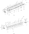
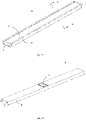
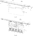
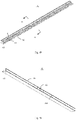
- an embodiment of the present application discloses a magnetically-adsorbed conductive track 1, which has an elongate flat shape, and includes a main body portion 10, a magnetic element 11, an insulating portion 12, a conductive portion 13 and end portions 14 arranged at both ends of the main body portion 10.
- the main body portion 10 extends along a length direction and has a flat shape, and includes an adsorbing wall 101, a mounting wall 102 arranged parallel and opposite to the adsorbing wall 101, a pair of side walls 103 connecting the adsorbing wall 101 and the mounting wall 102, and a pair of partition walls 104 parallel to the side walls 103 and located between the side walls 103.
- An outer surface of the adsorbing wall 101 is an adsorbing surface 1010; and an outer surface of the mounting wall 102 is a mounting surface 1020.
- Two long and narrow slots 107 are opened in a direction from the adsorbing wall 101 towards the mounting wall 102; the slots 107 are located above the conductive grooves 105 and in communication with the conductive grooves 105.
- the adsorbing wall 101 located between the slots 107 is further provided with at least two elliptical mounting holes 108 adjacent to both ends; and the number of mounting holes 108 is set according to a length of the magnetically-adsorbed conductive track 1.
- the magnetic element 11 and the mounting wall 102 are respectively provided with a mounting hole 110 and a mounting hole 109, the three are in communication in a height direction, and the mounting hole 109 of the mounting wall 102 is smaller in size than the mounting hole 110 of the magnetic element 11 and the mounting hole 108 of the adsorbing wall.
- the mounting holes 108, 109, 110 are used for allowing screws to run there-through; and screw heads are finally pressed on both sides of the mounting hole 109 of the mounting wall 102 and locked with a mounting foundation (a ceiling or a wall) to fix the magnetically-adsorbed conductive track 1 onto the mounting foundation.
- the mounting hole 108 of the adsorbing wall 101 is blocked and closed by a baffle (not shown); and specifically, the baffle may be provided on a surface of the magnetic element 11 by gluing.
- the insulating portion 12 is accommodated in the conductive groove 105, and includes a horizontal bottom wall 120, first side walls 121 extending vertically from the bottom wall 120, horizontal walls 123 formed by extending horizontally towards each other from the first side walls 121, and second side walls 122 formed by extending vertically from the horizontal walls 123.
- a distance between the second side walls 122 is smaller than a distance between the first side walls 121, so that a first space 124 is enclosed by the bottom wall 120 and the first side walls 121; and a second space 125 in communication with the first space 124 is enclosed by the horizontal walls 123 and the second side walls 122.
- the first space 124 and the second space 125 form an accommodating portion 126 of the insulating portion 12.
- the first side walls 121 are located between the side walls of the conductive groove 105, that is, located between the side wall 103 and the partition wall 104, and form a face-to-face contact, optimally, an interference fit; and the second side walls 122 are located between the side walls of the slot 107, so that the insulating portion 12 is laid over inner walls of the conductive groove 105 and the slot 107 to provide reliable insulation.
- a free end of the second side wall 122 is configured to be slightly lower than or flush with the adsorbing surface 1010.
- conductive portions 13 with a flat strip shape i.e., a positive electrode and a negative electrode; the positive electrode and the negative electrode each are inserted into the first space 124 of the insulating portion 12 so as to be located in the conductive groove 105, and each have both ends thereof extending beyond two end faces 100 of the main body portion 10, respectively.
- a conductive terminal of a lamp that is assembled to the magnetically-adsorbed conductive track 1 by adsorption enters the first space 124 through the second space 125 to form an electrical connection with the conductive portion 13.
- the magnetic element 11 has a flat sheet shape, and is inserted into the accommodating space 106 of the main body portion 10 and is at least attached to an inner surface of the adsorbing wall 101 so as to be adsorbed to a magnetic mounting portion of the lamp. Both ends of the magnetic element 11 are located in the accommodating space 106 without extending beyond the two end faces 100 of the main body portion 10.
- the magnetic element 11 may be respectively attached to the inner surface of the adsorbing wall 1 01 and the inner surface of the mounting wall 102; in a preferred embodiment of the present application, the magnetic element 11 is attached to the inner surface of the adsorbing wall 101, and two protruding strips 1022 provided on the inner surface of the mounting wall 102 are abutted against a surface of the magnetic element 11 to ensure assembly reliability.
- the end portions 14 are assembled on both ends of the main body portion 10 and form an electrical connection with the conductive portion 13.
- the end portion 14 includes an insulating body 140 and a conductive terminal 143 accommodated in the insulating body 140.
- each conductive terminal 143 includes a tabulate base portion 1430 located in a vertical plane, as well as a first docking portion 1431 and a second docking portion 1432 extending from the base portion 1430 towards opposite directions, respectively.
- the first and second docking portions 1431 and 1432 each include a pair of elastic members extending from upper and lower end edges of the base portion 1430 and bent towards each other; at a position adjacent to free ends, the elastic members are adjacent to each other and the free ends form guiding portions 1433 that are far away from each other.
- the insulating body 140 may be integrally formed with the conductive terminal 143, and includes a pair of conductive plug portions 144 formed by extending from a first end face 1403 thereof and a positioning plug portion 145 located between the conductive plug portions 144.
- the conductive plug portion 144 is provided with an opening on an end face; guiding portions 1433 of first docking portions 1431 of a pair of conductive terminals 143 are adjacent to the conductive plug portion 144, so that after the end portion 14 is assembled to the main body portion 10, the conductive portion 13 runs through the opening of the conductive plug portion 144 and is assembled between a pair of elastic members of the first docking portion 1431 to form an electrical connection with the conductive terminal 143.
- One surface of the conductive plug portion 144 further protrudes and extends to be provided with a guiding and positioning portion 1440 which is a pair of protruding strips whose width is equivalent to that of the slot 107; when the end portion 14 is assembled with the main body portion 10, the guiding and positioning portion 1440 enters into the slot 107.
- the positioning plug portion 145 is inserted into the accommodating space 106 and abutted against the end portion of the magnetic element 11 to provide positioning of the magnetic element 11 in the length direction.
- the insulating body 140 has a pair of positioning holes 146 that are formed by sinking from the second end face 1404 thereof towards the first end face 1403 and are located on an outer side, and a pair of conductive plug holes 147 located between the positioning holes 146 and adjacent to the positioning holes 146.
- the second docking portion 1432 is configured such that the guiding portion 1433 thereof is accommodated in the conductive plug hole 147 and is used to form an electrical connection with the adapter 2 (shown in the figures) so as to be electrically connected with other magnetically-adsorbed conductive track.
- the insulating body 140 further includes a first surface 1401 and an opposite second surface 1402, which are respectively flush with the adsorbing surface 1010 and the mounting surface 1020 of the main body portion 10 to form a smooth and flat structure to facilitate height reduction.
- the insulating body 140 is formed by collocating (assembling, combining, and matching) a first housing body 141 with a second housing body 142 arranged in up and down directions; and the conductive terminal 143 is sandwiched and accommodated between the first housing body 141 and the second housing body 142.
- the first surface 1401 is provided on the first housing body 141; and the second surface 1402 is provided on the second housing body 142. Therefore, the above-described structures are all formed by combining the first housing body 141 with the second housing body 142.
- the first housing body 141 extends from a surface thereof opposite to the first surface 1401 to form two conductive terminal accommodating grooves 1410, each conductive terminal accommodating groove 1410 includes two staggered cavities 1412 which are respectively in communication with the conductive plug portion 144 and the conductive plug hole 147 arranged in a staggered manner, to respectively accommodate the first docking portion 1431 and the second docking portion 1432 of the conductive terminal 143.
- the positioning elements 1411 may be a pair of positioning posts formed by protruding and extending along a height direction, or may also be positioning elements formed with positioning grooves.
- a positioning hole 146 is formed between the two conductive terminal accommodating grooves 1410 adjacent to the second end face, and the side wall.
- the second housing body 142 is provided with a partition wall 1422 for forming two cavities 1420, which cooperate with the conductive terminal accommodating groove 1410 to accommodate the conductive terminal 143; and a positioning element 1421 is formed inside the cavity 1420 and is matched with the positioning element 1411 of the first housing body 141.
- the cavity 1420 is respectively in communication with the conductive plug portion 144, the conductive plug hole 147 and the positioning hole 146.
- the magnetically-adsorbed conductive track 1 provided by the present application is respectively in direct face-to-face contact with the adsorbing surface of the lamp and the mounting foundation through the adsorbing surface 1010 and the mounting surface 1020, which effectively reduces the height of the magnetically-adsorbed conductive track 1;
- the conductive terminal 143 with flat structure design extending in opposite directions can effectively reduce the height of the end portion 14;
- the first surface 1401 and the second surface 1402 of the end portion 14 may be respectively flush with the adsorbing surface 1010 and the mounting surface 1020;
- the overall structure of the magnetically-adsorbed conductive track 1 is simple, which achieves ultra-thin structure design, and effectively reduces costs.
- the present application further provides an adapter 2, as shown in FIGS. 12 to 26 , the adapter 2 has varied forms, and can achieve cascaded connections of the magnetically-adsorbed conductive tracks 1 such as a straight-line connection, a planar L-shaped connection, a vertical L-shaped connection, a cross-shaped connection, and a T-shaped connection.
- a system consisting of the adapter 2 and at least two magnetically-adsorbed conductive tracks 1 is a magnetically-adsorbed conductive track system 1000.
- the adapter 2 achieves a mechanical and electrical connection with the magnetically-adsorbed conductive tracks 1; and the adapter 2 is flush with the mounting surfaces 1020 and the first surfaces 1401 of the end portions 14 of the magnetically-adsorbed conductive tracks 1 after the magnetically-adsorbed conductive tracks 1 are cascaded, and is respectively attached with the surfaces of the mounting foundation. Therefore, a thickness of the magnetically-adsorbed conductive track system 1000 is very small, which achieves ultra-thin structure design.
- the adapter 2 is not limited to the function of cascading magnetically-adsorbed conductive tracks 1, and may also cascade other electrical apparatuses.
- the adapter 2 has varied structures, which will be described below respectively.
- the adapter 2 includes an insulating body 20, and a conductive terminal 23 provided in the insulating body 20 and partially protruding and extending from the insulating body 20 to form an electrical connection with the end portion 14 of the magnetically-adsorbed conductive track 1.
- the insulating body 20 may be integrally formed with the conductive terminals 23, or may also include a first body 21 and a second body 22 collocated (assembled, combined, and matched) with the first body 21 along the height direction; and the conductive terminal 23 is sandwiched between the first body 21 and the second body 22.
- the insulating body 20 is of a square shape with four side edges; the insulating body 20 has a first surface 204 and an opposite second surface 206, and at least includes a main body portion 201 and a guiding portion 202 formed by extending from the main body portion 201.
- the conductive terminal 23 at least includes a base portion 231, and a docking portion 232 formed by extending from the base portion 231 and protruding beyond the main body portion 201 of the insulating body 20.
- the guiding portion 202 of the insulating body 20 is provided adjacent and arranged in parallel to the docking portion 232, so as to guide and protect the docking portion 232.
- the guiding portion 232 When the adapter 2 is docked with end portions 14 of different magnetically-adsorbed conductive tracks 1, the guiding portion 232 is assembled into the positioning hole 146, and meanwhile the docking portion 232 enters the end portion 14 from the positioning plug portion 145 and forms an electrical connection with the second docking portion 1432 of the conductive terminal 143.
- the first body 21 and the second body 22 each are formed with an accommodating space 24 located in a middle portion and a plurality of accommodating channels 25 in communication with the accommodating space 24, the accommodating space 24 is used for accommodating the base portion 231 of the conductive terminal 23; and the docking portion 232 is partially accommodated in the accommodating channel 25 and extends beyond the insulating body 20.
- the first surface 204 of the adapter 2 is flush with the mounting surface 1020 and the first surface 1401 of the end portion 14 of the magnetically-adsorbed conductive track 1, and all these surfaces are attached to the surface of the mounting foundation.
- the second surface 206 of the adapter 2 is flush with the adsorbing surface 1010 and the second surface 1402 of the end portion 14 of the magnetically-adsorbed conductive track 1, so that the overall structure is smooth, flat and simple, and the overall height is reduced.
- the adapter 2 has different structures. As shown in FIGS. 12 to 14 , if the magnetically-adsorbed conductive tracks 1 are connected in a cross shape, the adapter 2 includes a quadrilateral insulating body 20, and a pair of guiding portions 202 formed by extending from each side edge of the insulating body 20 and close to both ends of the insulating body 20.
- the conductive terminal 23 includes a quadrilateral base portion 231, and four groups of docking portions 232 formed by respectively extending in parallel from each side edge of the base portion 231; and each docking portion 232 is adjacent to its own guiding portion 202 and located between a pair of guiding portions 202 located on a same side.
- the docking portions 232 are arranged in pairs, i.e., a positive electrode and a negative electrode, respectively. Therefore, the adapter 2 may form a mechanical and electrical connection with the end portions 14 of four magnetically-adsorbed conductive tracks 1, respectively, and the four magnetically-adsorbed conductive tracks 1 are arranged in a cross shape to form a cross-shaped magnetically-adsorbed conductive track system 1000.
- the adapter 2 includes a quadrilateral insulating body 20 and mutually parallel guiding portions 202 extending from opposite two side edges of the insulating body 20.
- the conductive terminal 23 includes a quadrilateral base portion 231 and mutually parallel docking portions 232 extending from opposite two side edges of the base portion 231.
- the adapter 2 may form a mechanical and electrical connection with the end portions 14 of the two magnetically-adsorbed conductive tracks 1, respectively, and the two magnetically-adsorbed conductive tracks 1 are arranged in a cross shape to form a cross-shaped magnetically-adsorbed conductive track system 1000.
- the adapter 2 includes a quadrilateral insulating body 20 and mutually parallel guiding portions 202 formed by extending from adjacent two side edges of the insulating body 20.
- the conductive terminal 23 includes a quadrilateral base portion 231 and mutually parallel docking portions 232 formed by extending from adjacent two side edges of the base portion 231.
- the adapter 2 may form a mechanical and electrical connection with end portions 14 of two magnetically-adsorbed conductive tracks 1, respectively, and the two magnetically-adsorbed conductive tracks 1 are arranged in an L shape in a plane to form an L-shaped magnetically-adsorbed conductive track system 1000.
- the adapter 2 includes an L-shaped insulating body 20; and the insulating body 20 includes a flat plate-shaped first body 21 located in a horizontal plane and an L-shaped second body 22 assembled with the first body 21.
- the guiding portion 202 is formed by extending from a side wall of the first body 21 and extending from a side wall of a vertical portion of the second body 22, respectively.
- the conductive terminal 23 includes a first conductive terminal 233 located in a horizontal plane and a second conductive terminal 234 located in a vertical plane that is arranged perpendicular to the first conductive terminal 233.
- Each of the first conductive terminal 233 and the second conductive terminal 234 is formed with mutually parallel docking portions 232 extending from a horizontal side edge and a vertical side edge thereof, respectively.
- the other horizontal side edge of the first conductive terminal 233 extends to be formed with a protruding portion 2330; and the second conductive terminal 234 is correspondingly provided with an opening 2340 to accommodate the protruding portion 2330, so as to form an electrical connection there-between.
- positions of the opening 2340 and the protruding portion 2330 may be interchanged.
- the first conductive terminal 233 is sandwiched and accommodated between horizontal portions of the first body 21 and the second body 22; the second conductive terminal 234 is accommodated in a vertical portion of the second body 22.
- the adapter 2 may form a mechanical and electrical connection with end portions 14 of two magnetically-adsorbed conductive tracks 1, respectively, which are located in the horizontal plane and the vertical plane, respectively; and the two magnetically-adsorbed conductive tracks 1 are arranged in an L shape located in different planes to form a stereoscopic L-shaped magnetically-adsorbed conductive track system 1000.
- the first surface 204 is an upper surface of the first body 21; and the second surface 206 is a rear surface of the second body 22.
- the first surface 204 is flush with a mounting surface 1020 of a main body portion 10 and a first surface 1401 of an end portion 14 of one of the magnetically-adsorbed conductive tracks 1, and is flush with and attached to a horizontal surface of the mounting foundation;
- the second surface 206 is flush with a mounting surface 1020 of a main body portion 10 and a first surface 1401 of an end portion 14 of the other conductive track 1, and is flush with and attached to a vertical surface of the mounting foundation.
- the adapter 2 includes a quadrilateral insulating body 20 and mutually parallel guiding portions 202 formed by extending from three consecutive side edges of the insulating body 20.
- the conductive terminal 23 includes a quadrilateral base portion 231 and mutually parallel docking portions 232 formed by extending from three consecutive side edges of the base portion 231.
- the adapter 2 may form a mechanical and electrical connection with end portions 14 of three magnetically-adsorbed conductive tracks 1, respectively, and two magnetically-adsorbed conductive tracks 1 are arranged in a T shape to form a T-shaped magnetically-adsorbed conductive track system 1000.
- the magnetically-adsorbed conductive tracks 1 cascaded through the adapter 2 may be magnetically adsorbed to various electrical apparatuses and achieve electrical connections therewith, which is convenient and reliable.
- electrical apparatuses 3, 4, 5 and 6 that may be connected with the magnetically-adsorbed conductive track 1 are enumerated below; and the electrical apparatuses 3, 4, 5, 6 and the magnetically-adsorbed conductive tracks 1 constitute electrical systems 2000.
- the electrical apparatuses 3, 4, 5, 6 may be driving power supplies or lighting fixtures, intelligent control apparatuses or sensor modules, etc., among which a driving power supply 3 may receive mains power and convert the same into power required by the electrical apparatuses such as lighting fixtures 4, 5, 6 or intelligent control apparatuses or sensor modules; and the electrical apparatuses such as the lighting fixtures 4, 5, 6 or the intelligent control apparatuses or the sensor modules may also be provided with a driving apparatus to achieve power conversion.
- the electrical apparatus is not limited to the types as described above, and may also be any electrical apparatus configured to be matched with the above-described magnetically-adsorbed conductive track 1.
- the electrical apparatus is a driving power supply 3 that may be collocated with the magnetically-adsorbed conductive track 1 and supply power thereto.
- the driving power supply 3 and the magnetically-adsorbed conductive track 1 constitute an electrical system 2000 according to the first embodiment of the present application.
- the driving power supply 3 includes a main body portion 30, an electrical connection module 32, a conductor 33, and a driving module 34.
- the first housing body 321 and the second housing body 322 are hollowed; and after these two are collocated with each other, an accommodating space for accommodating the magnet module 323 and the conductive module 324 is formed. An opening is provided at one end of the first housing body 321 and the second housing body 322 for the conductor 33 to run therethrough.
- the magnet module 323 is composed of a plurality of pieces, arranged at intervals in the accommodating space and close to the second housing body 322, so as to adsorb the magnetic element 11 of the magnetically-adsorbed conductive track 1; after assembly, the surface of the second housing body 322 is attached to the adsorbing surface 1010 of the magnetically-adsorbed conductive track 1.
- the collocating portion 3220 that is assembled, together with the conductive terminal 3241, into the magnetically-adsorbed conductive track 1 enhances a binding force of the driving power supply 3 and the magnetically-adsorbed conductive track 1; the collocating surface 32230 that is attached to the adsorbing surface 1010 ensures a lowest height of the electrical system 2000, and an effective adsorption between the magnet module 323 and the magnetic element 11. Therefore, the driving power supply 3 provided by the present application may be adsorbed to the magnetically-adsorbed conductive track 1 and electrically connected with the conductive portion 13 to achieve a mechanical connection and a power supply, which is convenient for use.
- the magnet module 45 includes two strip-shaped, fixed portions 450, a plurality of pairs of positioning elements 4501 are arranged on a surface of the magnet module 45, groups of magnets 451 are stacked in parallel between the positioning elements 4501, and all of which are accommodated in the magnet module accommodating portion 406.
- the lighting module 47 includes an elongated light source substrate 470, as well as a plurality of light sources 471 and at least two electrodes 472 arranged on the light source substrate 470; the light sources 471 and the electrodes 472 are respectively arranged along the height direction; in a preferred embodiment of the present application, the electrodes 472 are arranged in the middle of a lower part of the light source substrate 470 and include a positive electrode and a negative electrode; in other preferred embodiments, it may also include electrodes for transmitting various control signals, for dimming and for color adjustment.
- the lighting module 47 is accommodated in at least one of the lighting module accommodating portions 405; and in other embodiments, two groups of lighting modules 47 may be provided and be respectively accommodated in a group of lighting module accommodating portions 405 adjacent to the side walls 402.
- the light source 471 of the lighting module 47 faces the side wall of the light guide element 42, so that light emitted from the light source 471 enters the inside of the light guide element 42 from the side wall of the light guide element 42, undergoes multiple reflections by the upper and the lower surfaces, and then exits from at least one surface, e.g., the light exits from a surface facing the cover 43 in this embodiment; and the reflective layer 41 is located on the other surface of the light guide element 42, and reflects the light incident on the other surface to reenter the light guide element 42 to increase light effect.
- Two groups of first conductive terminals 4631 are respectively arranged at four corners of the base body 463 to be perpendicular to the base body 463 by adopting perforation welding or other connecting modes such as surface welding, and are electrically connected with circuits inside the base body 463.
- the second conductive terminal 4632 is connected with and parallel to one surface of the base body 463 by surface welding or other connecting modes, and is electrically connected with circuits inside the base body 463, so as to be electrically connected with the first conductive terminal 4631.
- the first housing body 461 and the second housing body 462 are engaged with each other in a snap-fit manner, and are engaged with the opening 4010 of the lighting fixture 4 in a snap-fit manner.
- the second housing body 462 includes a bottom wall 4620 and a pair of side walls 4621 formed by extending in a direction from both sides of the bottom wall 4620 towards the first housing body 461. A middle portion of the side wall 4621 is broken and folded outwards to form a snap-fitting portion 4622, which is engaged with a peripheral wall of the opening 4010 in a snap-fit manner.
- the bottom wall 4620 Four corners of the bottom wall 4620 are provided with four round holes for the first conductive terminals 4621 to run therethrough, and a surface of the bottom wall 4620 that faces the magnetically-adsorbed conductive track 1 protrudes and extends so as to be formed with a plurality of collocating portions 4623; the first conductive terminal 4631 is located between the collocating portions 4623 and extends beyond the collocating portions 4623; the collocating portions 4623 may protect the first conductive terminals 4631, and extend, together with the first conductive terminals 4631, into the second space 125 of the magnetically-adsorbed conductive track 1; and the first conductive terminal 4631 further enters the first space 124 and be elastically abutted against the conductive portion 13 to form an electrical connection.
- the bottom wall 4620 is attached to the adsorbing surface 1010 of the magnetically-adsorbed conductive track 1; and the magnet 451 adsorbs the magnetic element 11 behind the adsorbing surface 1010.
- the second conductive terminal 4632 partially extends beyond the side walls of the first housing body 461 and the second housing body 462 that are arranged perpendicular to the side walls 4621, and is used for elastically abutting against the electrode 472 of the lighting module 47.
- the collocating portions 4623 are assembled into the magnetically-adsorbed conductive track 1 together with the first conductive terminal 4631, which enhances a binding force of the magnetically-adsorbed conductive track 1 and the lighting fixture 4, ensures sufficiently small height and small thickness of the electrical system 2000, and achieves a simple structure.
- the present application further provides a lighting fixture 5 assembled by adsorption to the magnetically-adsorbed conductive track 1 according to a third embodiment of the present application; and in the embodiment of the present application, the lighting fixture 5 is a grid lamp.
- the lighting fixture 5 and the magnetically-adsorbed conductive track 1 constitute an electrical system 2000 according to the third embodiment of the present application.
- the lighting fixture 5 includes a lamp body 50, a cover 53 assembled on the lamp body 50, a lighting module 57 accommodated between the lamp body 50 and the cover 53, an electrical connection module 51 pivotally coupled to the lamp body 50, and a rotating shaft 52 sleeved between the electrical connection modules 51 and the lamp body 50.
- the lighting module 57 includes a light source substrate 570, a light source 571 provided on the light source substrate 570, a primary optical element 572 covering an outer side of the corresponding light source 571, and a secondary optical element 573 located at one end of the primary optical element 572.
- the light source may be an LED particle or a COB light source
- the primary optical element 572 is a reflector, which is fixed on the light source substrate 570, has one end covering the light source 571 and the other end used as a light exit
- the secondary optical element 573 has a flat plate shape and is located at the light exit of the reflector 572
- the secondary optical element 573 is provided with a plurality of polarizer structures at intervals to expand a light exiting angle of the light from the light exit of the reflector 572 in a lateral direction.
- the cover 53 includes a main body portion 530, a plurality of grids 531 are provided inside the main body portion 530, and the number of the grids 531 is corresponding to the number of reflectors 572.
- the main body portion 530 extends beyond the grids 531, and a plurality of snap-fitting portions 532 are formed at intervals on the outer periphery of the side wall of the main body portion 530; the cover 53, after being assembled to the lamp body 50, is connected with the snap-fitting portion 501 of the inner wall of the lamp body 50 in a snap-fitting manner; in the embodiment of the present application, the snap-fitting portion 530 of the cover 53 is a hooker; the snap-fitting portion 501 of the lamp body 50 is a recess formed therein; and the hooker and the recess may be interchanged.
- the secondary optical element 573 is sandwiched between the primary optical element 572 and the grids 531.
- the grid 531 has one end provided with an opening as a light entry to correspondingly receive incident light from a lens module, and the other end also provided with an opening as a light exit; and the side wall of the grid extends into a horn shape.
- a range of the above-described emergent light passing through the secondary optical element 573 is equivalent to a horn mouth for light to exit.
- the electrical connection module 51 includes a housing body 510 extending in the longitudinal direction, a driving portion 58 accommodated in the housing body 510, a conductive module 56 and a magnet module 55.
- the housing body 510 includes a main body portion 54, a cap body 59 assembled on the main body portion 54, a driving portion 58, a conductive module 56 and a magnet module 55 accommodated between the main body portion 54 and the cap body 59.
- the lamp body 50 also protrudes and extends to be provided with a semicircular pivot portion 502, and is formed with a rotating shaft hole (not numbered), so that both ends of the above-described rotating shaft 52 are respectively accommodated in the rotating shaft hole 5410 and the rotating shaft hole of the pivot portion 502 of the lamp body 50; the adapting module 54 and the lamp body 50 may be rotated relative to each other, so that the range of the emergent light of the lighting module 57 of the lamp body 50 may be adjusted.
- the conductive module 56 In order to provide the power obtained from the magnetically-adsorbed conductive track 1 to the lighting module 57, the conductive module 56 needs to be electrically connected with the driving portion 58; in the embodiment of the present application, the base body 560 of the conductive module 56 is electrically connected with the driving portion 58 through a conductor (not shown); however, in other embodiments, the base body 560 may also be provided with an elastic pin-like conductive terminal 561 relative to the other surface where the conductive terminal 561 is provided; and the driving portion 58 is provided, on a circuit board thereof, with a conductive sheet to be abutted against the elastic pin-like conductive terminal to form an electrical connection.
- the driving portion 58 is electrically connected with the lighting module 57 through a conductor, to convert the mains power to the power required by the lighting module 57 and supply the same to the lighting module 57. Since the driving power supply 3 converts the mains power into a 58 V power supply, the lighting fixture 5 needs to be provided with a driving portion 58 to further convert the 58 V power supply into a voltage required by the lighting fixture 5.
- Two groups of magnet modules 55 are provided, and each include at least two magnets; and the rectangular frame body 540 of the main body portion 54 is formed with an accommodating space to accommodate the magnet module 55, the conductive module 56 and the driving portion 58.
- the cap body 59 is locked to the main body portion 54 by screws.
- the cap body 59 is substantially flat plate-shaped and provided with openings 591 at both ends; the magnet module 55 is accommodated in the accommodating space of the main body portion 54, protrudes from the opening 591 and is exposed to the cap body 59.
- an outer surface of the cap body 59 that faces the adsorbing surface 1010 of the magnetically-adsorbed conductive track 1 is provided with a strip-shaped collocating portion 590 located outside the opening 591; at positions corresponding to the conductive terminals 561 of the conductive module 56, the collocating portion 590 is formed with a plurality of grooves 592 which are used as conductive terminal accommodating portions 592.
- the conductive terminal 561 of the conductive module 56 protrudes and extends beyond the surface of the collocating portion 590 of the cap body 59, to be electrically connected with the magnetically-adsorbed conductive track 1.
- the collocating portion 590 and the conductive terminal 561 jointly extend into the second space 125 of the magnetically-adsorbed conductive track 1; and the conductive terminal 561 further enters the first space 124 and is elastically abutted against the conductive portion 13 to form an electrical connection.
- the surface of the cap body 590 is attached to the adsorbing surface 1010 of the magnetically-adsorbed conductive track 1; and the magnet 55 adsorbs the magnetic element 11 behind the adsorbing surface 1010.
- the collocating portion 590 together with the conductive terminal 561, is assembled into the magnetically-adsorbed conductive track 1, which enhances a binding force of the magnetically-adsorbed conductive track 1 and the lighting fixture 5, ensures sufficiently small height and small thickness of the electrical system 2000, and achieves a simple structure.
- the lighting module 57 may emit light as needed, for example, in a controllable, dimmable, and color-adjustable manner, and may achieve angle adjustment relative to the adapting module 54.
- the convenient assembly mode greatly facilitates the use.
- the lighting fixture 6 includes a main body 60 extending in a longitudinal direction, a cap body 62 formed by extending in the longitudinal direction and assembled to the main body 60, a light guide element 61 assembled to the main body 60 and the cap body 62, a magnet module 65, an electrical connection module 66, a lighting module 67 and an end cap 64 assembled to both ends of the main body 60 and the cap body 62.
- the main body 60 includes a conductive track accommodating portion 601, a magnet module accommodating portion 602, a lighting module accommodating portion 603, a light guide element accommodating portion 604, a cap body accommodating portion 605 and an electrical connection module accommodating portion 606.
- the main body 60 includes an inverted U-shaped frame body 607 which delimits the above-described magnet module accommodating portion 602; and the U-shaped frame body 607 includes a base portion 6070 and a pair of side walls 6071 formed by extending perpendicularly from two ends of a surface of the base portion 6070.
- a wedge-shaped extending portion 6074 is raised from the vicinity of the base portion 6070 and has a bottom wall connected with the L-shaped side wall 6072; and the wedge-shaped extending portion 6074 is formed with the above-described light guide element accommodating portion 604 and has a hollowed configuration, thereby reducing the weight and increasing the strength.
- An L-shaped cap body accommodating portion 605 is formed between the L-shaped side wall 6072 and the side wall 6071. A rear portion of the body 60 is partially removed to form the electrical connection module accommodating portion 606.
- the cap body 62 is substantially L-shaped, and includes a first cap body 621 accommodated in the cap body accommodating portion 605 and a second cap body 622 formed by vertically extending from the first cap body 621.
- the first cap body 621 is hollowed and has a protruding and extending portion 6210 which is in an interference fit with an interference portion 6075 formed by protruding and extending from a surface of the L-shaped side wall 6072 that faces the first cap body 621.
- the second cap body 622 partially covers an outer side of the lighting module accommodating portion 603, that is, the outer side of the lighting module 67, and has a U-shaped engagement portion 6220 formed at a free end thereof.
- the first cap body 621 is also locked with the L-shaped side wall 6072 of the main body 60 by screws.
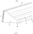
- the light guide element 61 is wedge-shaped and laid on the surface of the light guide element accommodating portion 604; the light guide element 61 includes a wedge-shaped main body portion 610, a light incident surface 611 on one side thereof, and a light emergent surface 612 having a certain angle with the light incident surface 611; and the light emergent surface 612 is a main surface of the main body portion 610 and faces the outside.
- the light incident surface 611 faces the light source 671 of the lighting module 67 and receives incident light from the light source 671; the incident light undergoes multiple times of total reflections in the wedge-shaped main body portion 610 and exits from the light emergent surface 612.
- the surface of the light emergent surface 612 may be etched or formed with dots, or the light guide element 61 may be doped with particles of different concentrations therein, to achieve scattering and light emission.
- the magnet module 65 includes a plurality of groups of magnets 650 and strip-shaped fixing portions 651 arranged at intervals; the magnets 650 and the fixing portions 651 are arranged, in a strip shape, at intervals and are assembled through the magnet module accommodating portion 602, so that at least one surface of the magnet module 65 faces the conductive track accommodating portion 601.
- the electrical connection module 66 includes a housing body 660 and an electrical connector 663 accommodated in the housing body 660.
- the housing body 660 includes a first housing body 661 and a second housing body 662 collocated with each other; and the electrical connector 663 is sandwiched between the first housing body 661 and the second housing body 662.
- the electrical connector 663 includes a base body 6630, a first conductive terminal 6631 provided on one surface of the base body 6630 and formed by extending vertically from the base body 6630, and a second conductive terminal 6632 provided on the other surface of the base body 6630 and formed by extending vertically from the base body 6630.
- the first conductive terminal 6631 is an elastic pin-like conductive terminal and is electrically connected with the circuit inside the base body 6630.
- the second conductive terminal 6632 is an elastic element, preferably a spring; and the base body 6630 is provided with an opening to accommodate the second conductive terminal 6632 and is electrically connected with the second conductive terminal 6632.
- the first housing body 661 includes a bottom wall 6610 and a side wall 6611 formed by extending from the bottom wall 6610. A middle portion of the side wall 6611 is provided with a first engagement portion 6612, which is a snap-fitting portion.
- the bottom wall 6610 is provided with a second engagement portion 6614 and a terminal accommodating portion 6613, respectively; in the embodiment of the present application, the second engagement portion 6614 is an opening; and the terminal accommodating portion 6613 is a circular opening for the second conductive terminal 6632 to run therethrough and then extend beyond the bottom wall 6610 of the first housing body 661.
- the second engagement portion 6624 is a cylinder, which is used for forming an interference fit with the second engagement portion 6614 of the first housing body 661 and has a guiding effect.
- the second engagement portions 6614 and 6624 are interchangeable.
- the terminal accommodating portion 6623 is a circular opening running through the bottom wall 6620. Both sides of the other surface of the bottom wall 6620 respectively extend to form strip-shaped collocating portions 6625, which are arranged at intervals in a row, with the first conductive terminals 6631; and the first conductive terminals 6631 extend beyond the collocating portions 6625.
- the magnetically-adsorbed conductive track 1 is accommodated in the above-described conductive track accommodating portion 601, and the adsorbing surface 1010 thereof is attached to the bottom wall of the conductive track accommodating portion 601; and the L-shaped side wall 6072 and extending portions 641 of the end cap 64 are respectively attached to the side wall 103 of the magnetically-adsorbed conductive track 1.
- the first conductive terminal 6631 and the collocating portion 6625 are jointly assembled into the second space 125 of the insulating portion 12 of the magnetically-adsorbed conductive track 1; and the first conductive terminal 6631 continues to extend into the first space 124 and is elastically abutted against the conductive portion 13 provided in the first space 124, to form an electrical connection.
- the collocating portion 6625, together with the first conductive terminal 6631, is assembled to the magnetically-adsorbed conductive track 1, which enhances a binding force of the magnetically-adsorbed conductive track 1 and the lighting fixture 6, ensures sufficiently small height and small thickness of the electrical system 2000, and achieves a simple structure.
- the magnetically-adsorbed conductive track 1, the adapter 2, the electrical apparatuses 3, 4, 5, 6, as well as the magnetically-adsorbed conductive track system 1000 and the electrical system 2000 constituted thereby as provided by the present application have simple structures, effectively reduced heights, and are convenient for assembly.
- the electrical apparatuses may also be lighting fixtures such as down lamps, spot lamps, dining chandeliers, and ceiling lamps.
Landscapes
- Engineering & Computer Science (AREA)
- General Engineering & Computer Science (AREA)
- Details Of Connecting Devices For Male And Female Coupling (AREA)
Abstract
Description
- The present application claims the priority of
Chinese Patent Application for an invention entitled "Magnetically-Adsorbed Conductive Track" filed with the Patent Office of China on November 7, 2019, with the Application No. 201911086105.2 Chinese Patent Application for a utility model entitled "Magnetically-Adsorbed Conductive Track" filed with the Patent Office of China on November 7, 2019, with the Application No. 201921918697.5 Chinese Patent Application for an invention entitled "Electrical Apparatus and Electrical system" filed with the Patent Office of China on November 7, 2019, with the Application No. 201911086264.2 Chinese Patent Application for a utility model entitled "Electrical Apparatus and Electrical system" filed with the Patent Office of China on November 7, 2019, with the Application No. 201921918384.X Chinese Patent Application for an invention entitled "Adapter and Magnetically-Adsorbed Conductive Track System" filed with the Patent Office of China on November 7, 2019, with the Application No. 201911086107.1 Chinese Patent Application for a utility model entitled "Adapter and Magnetically-Adsorbed Conductive Track System" filed with the Patent Office of China on November 7, 2019, with the Application No. 201921918669.3 - The present application relates to the field of lighting technology, and more particularly, to a magnetically-adsorbed conductive track, an adapter, an electrical apparatus and an electrical system.
- A track lamp mainly includes a track (a conductive track) fixed on a ceiling or a wall and various lamps that can slide along the track, such as spot lamps, line lamps, etc.
- The track usually has a certain height or thickness. On the basis of some instances, the track still has certain rooms for improvement, for example, it may be lighter and thinner with lower cost.
- In addition, a cascaded structure of the track also has room for improvement, for example, it may be lighter and thinner, smaller in thickness, and achieve a smooth, efficient, and fast connection.
- When an electrical apparatus is installed on the track to obtain power, the reliability of mechanical and electrical engagement therebetween is also a technical problem to be solved in the prior art. In some instances, after a conductive terminal of the electrical apparatus is assembled to a conductive stripe in the track, if the reliability of the mechanical structure is poor, an electrical connection between the conductive terminal and the conductive stripe will also be affected, which further affects the use of the electrical apparatus.
- In order to solve the above-described problems, the present application provides a magnetically-adsorbed conductive track, an adapter, an electrical apparatus, and an electrical system.
- According to the first aspect, it provides an electrical system, including: at least two magnetically-adsorbed conductive tracks, at least one electrical apparatus and at least one adapter; the at least one adapter cascades the at least two magnetically-adsorbed conductive tracks; the magnetically-adsorbed conductive track includes a main body portion extending along a length direction and having a flat shape, the main body portion includes: an adsorbing wall, a mounting wall arranged opposite to the adsorbing wall, a pair of side walls connecting the adsorbing wall and the mounting wall, and a pair of partition walls parallel to the side walls and located between the side walls; the side walls and the partition walls, respectively, together with the adsorbing wall and the mounting wall, form conductive grooves extending in the length direction and located at both sides, and form an accommodating space located between the conductive grooves; a slot is formed in a direction from the adsorbing wall towards the mounting wall and is in communication with the conductive grooves; a pair of insulating portions, each accommodated in the conductive groove and provided with an accommodating portion in communication with the slot of the adsorbing wall; a pair of conductive portions, each accommodated in the accommodating portion of the insulating portion; and a magnetic element, accommodated in the accommodating space and attached to the adsorbing wall; the insulating portion is attached inside the conductive groove; and the accommodating portion of the insulating portion includes: a first space for accommodating the conductive portion, and a second space which is in communication with the first space and is smaller than the first space, allowing a conductor of a lamp to enter the first space from the second space to be electrically connected with the conductive portion; the electrical apparatus includes: a main body formed by extending along a longitudinal direction, an electrical connection module collocated with the main body, and a magnet module; the electrical connection module includes: a housing body formed by extending along the longitudinal direction, an elastic conductive terminal accommodated in the housing body, and a collocating portion provided on a surface of the housing body that faces the magnetically-adsorbed conductive track and extending in the longitudinal direction; the elastic conductive terminal and the collocating portion are arranged longitudinally in a row; and the elastic conductive terminal extends beyond the collocating portion along a height direction; the elastic conductive terminal and the collocating portion are jointly collocated into the magnetically-adsorbed conductive track; the elastic conductive terminal of the electrical apparatus and the collocating portion are jointly collocated into the second space of the magnetically-adsorbed conductive track; and the elastic conductive terminal further extends into the first space and is elastically abutted against a surface of the conductive portion to form an electrical connection; the adapter includes: an insulating body, and a conductive terminal arranged in the insulating body and partially protruding and extending out of the insulating body; the conductive terminal has a flat sheet shape and includes: a base portion provided in the insulating body, and a docking portion protruding and extending out of the insulating body; the insulating body protrudes and extends at the docking portion adjacent to the conductive terminal to form a guiding portion spaced apart from the conductive terminal, and the insulating body is configured such that the guiding portion and the docking portion are jointly assembled into the at least two electrical apparatuses to achieve an electrical connection of the two electrical apparatuses.
- According to the second aspect, it provides a magnetically-adsorbed conductive track system configured to be mounted on a surface of a mounting foundation, including an adapter and at least two magnetically-adsorbed conductive tracks; the adapter includes an insulating body, and a conductive terminal arranged in the insulating body and partially protruding and extending out of the insulating body; the conductive terminal has a flat sheet shape, and includes a base portion arranged in the insulating body and a docking portion protruding and extending out of the insulating body; the insulating body protrudes and extends at the docking portion adjacent to the conductive terminal to form a guiding portion spaced apart from the conductive terminal, and the insulating body is configured such that the guiding portion and the docking portion are jointly assembled into the at least two electrical apparatuses to achieve an electrical connection of the at least two electrical apparatuses; the magnetically-adsorbed conductive track includes a main body portion, the main body portion extends along a length direction and has a flat shape, and the main body portion includes an adsorbing wall, a mounting wall arranged opposite to the adsorbing wall, a pair of side walls connecting the adsorbing wall and the mounting wall, and a pair of partition walls parallel to the side walls and located between the side walls; the side walls and the partition walls, respectively, together with the adsorbing wall and the mounting wall, form conductive grooves extending in the length direction and located at both sides, and form an accommodating space located between the conductive grooves; a slot is formed in a direction from the adsorbing wall towards the mounting wall and is in communication with the conductive grooves; a pair of insulating portions, each accommodated in the conductive groove and provided with an accommodating portion in communication with the slot of the adsorbing wall; a pair of conductive portions, each accommodated in the accommodating portion of the insulating portion; and a magnetic element accommodated in the accommodating space and attached to the adsorbing wall; the magnetically-adsorbed conductive track includes a main body portion and end portions arranged at both ends of the main body portion; the main body portion is embedded with the conductive portion; the end portion is configured to be electrically connected with the conductive portion and the conductive terminal of the adapter at the same time, and to be mechanically connected with the main body portion of the magnetically-adsorbed conductive track and the adapter at the same time.
- According to the third aspect, it provides a magnetically-adsorbed conductive track, configured to be assembled on a mounting foundation and be magnetically adsorbed to and electrically connected with an electrical apparatus, including: a main body portion, extending along a length direction and having a flat shape, and including an adsorbing wall, a mounting wall arranged opposite to the adsorbing wall, a pair of side walls connecting the adsorbing wall and the mounting wall, and a pair of partition walls parallel to the side walls and located between the side walls; the side walls and the partition walls, respectively, together with the adsorbing wall and the mounting wall, form conductive grooves extending in the length direction and located at both sides, and form an accommodating space located between the conductive grooves; a slot is formed in a direction from the adsorbing wall towards the mounting wall, and is in communication with the conductive grooves; a pair of insulating portions, each accommodated in the conductive groove and formed with an accommodating portion in communication with the slot of the adsorbing wall; a pair of conductive portions, each accommodated in the accommodating portion of the insulating portion; and a magnetic element, accommodated in the accommodating space and attached to the adsorbing wall.
- According to the fourth aspect, it provides an adapter configured to at least cascade two electrical apparatuses, including an insulating body, and a conductive terminal arranged in the insulating body and partially protruding and extending out of the insulating body; wherein, the conductive terminal has a flat sheet shape, and includes a base portion provided in the insulating body and a docking portion protruding and extending out of the insulating body; the insulating body protrudes and extends at the docking portion adjacent to the conductive terminal to form a guiding portion spaced apart from the conductive terminal, and the insulating body is configured such that the guiding portion and the docking portion are jointly assembled into the at least two electrical apparatuses to achieve an electrical connection of the two electrical apparatuses.
- According to the fifth aspect, it provides an electrical apparatus magnetically adsorbable to a magnetically-adsorbed conductive track, including: a main body formed by extending along a longitudinal direction, an electrical connection module collocated with the main body, and a magnet module; the electrical connection module includes a housing body formed by extending along the longitudinal direction, an elastic conductive terminal accommodated in the housing body, and a collocating portion provided on a surface of the housing body that faces the magnetically-adsorbed conductive track and extending in the longitudinal direction; the elastic conductive terminal and the collocating portion are arranged longitudinally in a row; and the elastic conductive terminal extends beyond the collocating portion along a height direction; the elastic conductive terminal and the collocating portion are jointly collocated to enter the magnetically-adsorbed conductive track.
- The drawings described herein are used to provide further understanding of the present application and constitute a part of the present application. Illustrative embodiments of the present application and description thereof are used to explain the present application, and do not constitute any improper limit to the present application. In the drawings:
Description of reference signs: -
FIG. 1 is a stereoscopic view of a magnetically-adsorbed conductive track provided by an embodiment of the present application; -
FIG. 2 is a stereoscopic view of the magnetically-adsorbed conductive track shown inFIG. 1 from another angle; -
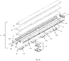
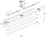
FIG. 3 is a stereoscopic exploded view of a part of the magnetically-adsorbed conductive track shown inFIG. 1 ; -
FIG. 4 is a stereoscopic exploded view of a part of the magnetically-adsorbed conductive track shown inFIG. 2 ; -
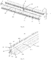
FIG. 5 is a stereoscopic view of an end portion of a magnetically-adsorbed conductive track provided by the embodiment of the present application; -
FIG. 6 is a stereoscopic exploded view of the end portion shown inFIG. 5 ; -
FIG. 7 is a stereoscopic view of the end portion shown inFIG. 5 from another angle; -
FIG. 8 is a stereoscopic exploded view of the end portion shown inFIG. 7 ; -
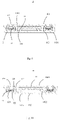
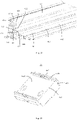
FIG. 9 is a cross-sectional view of the magnetically-adsorbed conductive track shown inFIG. 1 along a line A-A; -
FIG. 10 is a cross-sectional view of the magnetically-adsorbed conductive track shown inFIG. 1 along a line B-B; -
FIG. 11 is a cross-sectional view of the magnetically-adsorbed conductive track shown inFIG. 1 along a line C-C; -
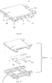
FIG. 12 is a stereoscopic view of an adapter according to a first embodiment of the present application; -
FIG. 13 is a stereoscopic exploded view of the adapter shown inFIG. 12 ; -
FIG. 14 is a stereoscopic view of a magnetically-adsorbed conductive track system according to the first embodiment of the present application; -
FIG. 15 is a stereoscopic view of an adapter according to a second embodiment of the present application; -
FIG. 16 is a stereoscopic exploded view of the adapter shown inFIG. 15 ; -
FIG. 17 is a stereoscopic view of a magnetically-adsorbed conductive track system according to the second embodiment of the present application; -
FIG. 18 is a stereoscopic view of an adapter according to a third embodiment of the present application; -
FIG. 19 is a stereoscopic exploded view of the adapter shown inFIG. 18 ; -
FIG. 20 is a stereoscopic view of a magnetically-adsorbed conductive track system according to the third embodiment of the present application; -
FIG. 21 is a stereoscopic view of an adapter according to a fourth embodiment of the present application; -
FIG. 22 is a stereoscopic exploded view of the adapter shown inFIG. 21 ; -
FIG. 23 is a stereoscopic view of a magnetically-adsorbed conductive track system according to the fourth embodiment of the present application; -
FIG. 24 is a stereoscopic view of an adapter according to a fifth embodiment of the present application; -
FIG. 25 is a stereoscopic exploded view of the adapter shown inFIG. 24 ; -
FIG. 26 is a stereoscopic view of a magnetically-adsorbed conductive track system according to the fifth embodiment of the present application; -
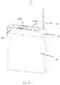
FIG. 27 is a stereoscopic view of an electrical apparatus that may be collocated with a magnetically-adsorbed conductive track according to the first embodiment of the present application; -
FIG. 28 is a stereoscopic exploded view of a part of the electrical apparatus shown inFIG. 27 ; -
FIG. 29 is a stereoscopic view of an electrical system according to the first embodiment of the present application; -
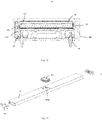
FIG. 30 is a cross-sectional view of the electrical system according to the first embodiment of the present application; -
FIG. 31 is a partial enlarged view of the cross-sectional view shown inFIG. 30 ; -
FIG. 32 is a stereoscopic view of an electrical apparatus that may be collocated with a magnetically-adsorbed conductive track according to the second embodiment of the present application; -
FIG. 33 is a stereoscopic view of the electrical apparatus shown inFIG. 32 from another angle; -
FIG. 34 is a cross-sectional view of the electrical apparatus shown inFIG. 32 taken along a line D-D; -
FIG. 35 is a stereoscopic exploded view of a part of the electrical apparatus shown inFIG. 32 ; -
FIG. 36 is a stereoscopic exploded view of the electrical apparatus shown inFIG. 32 ; -
FIG. 37 is a stereoscopic exploded view of the electrical apparatus shown inFIG. 33 ; -
FIG. 38 is a stereoscopic view of an electrical connection module of the electrical apparatus shown inFIG. 32 ; -
FIG. 39 is a stereoscopic exploded view of the electrical connection module shown inFIG. 38 ; -
FIG. 40 is a stereoscopic view of the electrical connection module shown inFIG. 38 from another angle; -
FIG. 41 is a stereoscopic view of an electrical system according to the second embodiment of the present application; -
FIG. 42 is a cross-sectional view of the electrical system shown inFIG. 41 taken along a line E-E; -
FIG. 43 is a stereoscopic view of an electrical apparatus that may be collocated with a magnetically-adsorbed conductive track according to the third embodiment of the present application; -
FIG. 44 is a stereoscopic exploded view of a part of the electrical apparatus shown inFIG. 43 ; -
FIG. 45 is a cross-sectional view of the electrical apparatus shown inFIG. 43 taken along a line F-F; -
FIG. 46 is a stereoscopic view of an electrical connection module of the electrical apparatus shown inFIG. 43 ; -
FIG. 47 is a stereoscopic view of an electrical system according to the third embodiment of the present application; -
FIG. 48 is a cross-sectional view of the electrical system shown inFIG. 47 along a line G-G; -
FIG. 49 is a stereoscopic view of an electrical apparatus that may be collocated with a magnetically-adsorbed conductive track according to the fourth embodiment of the present application; -
FIG. 50 is a stereoscopic view of the electrical apparatus shown inFIG. 49 from another angle; -
FIG. 51 is a stereoscopic exploded view of the electrical apparatus shown inFIG. 49 ; -
FIG. 52 is a stereoscopic exploded view of the electrical apparatus shown inFIG. 50 ; -
FIG. 53 is a partially enlarged view of a main body of the electrical apparatus shown inFIG. 51 ; -
FIG. 54 is an enlarged view of a stereoscopic assembly view of a part of the electrical apparatus shown inFIG. 49 ; -
FIG. 55 is a stereoscopic view of an electrical connection module of the electrical apparatus shown inFIG. 49 ; -
FIG. 56 is a stereoscopic view of the electrical connection module shown inFIG. 55 from another angle; -
FIG. 57 is a stereoscopic exploded view of the electrical connection module shown inFIG. 56 ; -
FIG. 58 is a cross-sectional view of the electrical apparatus shown inFIG. 49 taken along a line H-H; -
FIG. 59 is a stereoscopic view of an electrical system according to the fourth embodiment of the present application; -
FIG. 60 is an enlarged view of a part of the electrical system shown inFIG. 59 ; and -
FIG. 61 is a cross-sectional view of the electrical system shown inFIG. 59 taken along a line I-I. - In order to make objectives, technical details and advantages of the present application apparent, the technical solutions of the present application will be described in a clearly and fully understandable way in connection with specific embodiments of the present application and corresponding drawings. It is obvious that the described embodiments are just a part but not all of the embodiments of the present application. Based on the described embodiments herein, those ordinarily skilled in the art can acquire other embodiment(s), without any inventive work, which should be within the scope of the present application.
- The technical solutions provided by the embodiments of the present application will be described in details below in conjunction with the accompanying drawings.
- As shown in
FIGS. 1 to 4 , and in conjunction withFIGS. 9 to 11 , an embodiment of the present application discloses a magnetically-adsorbedconductive track 1, which has an elongate flat shape, and includes amain body portion 10, amagnetic element 11, an insulatingportion 12, aconductive portion 13 andend portions 14 arranged at both ends of themain body portion 10. - The
main body portion 10 extends along a length direction and has a flat shape, and includes an adsorbingwall 101, a mountingwall 102 arranged parallel and opposite to the adsorbingwall 101, a pair ofside walls 103 connecting the adsorbingwall 101 and the mountingwall 102, and a pair ofpartition walls 104 parallel to theside walls 103 and located between theside walls 103. An outer surface of the adsorbingwall 101 is an adsorbingsurface 1010; and an outer surface of the mountingwall 102 is a mountingsurface 1020. Theside walls 103 and thepartition walls 104 as described above, respectively, together with the adsorbingwall 101 and the mountingwall 102, formconductive grooves 105 extending in the length direction and located on both sides, and form anaccommodating space 106 located between theconductive grooves 105. Two long andnarrow slots 107 are opened in a direction from the adsorbingwall 101 towards the mountingwall 102; theslots 107 are located above theconductive grooves 105 and in communication with theconductive grooves 105. The adsorbingwall 101 located between theslots 107 is further provided with at least two elliptical mountingholes 108 adjacent to both ends; and the number of mountingholes 108 is set according to a length of the magnetically-adsorbedconductive track 1. Corresponding to the mountinghole 108, themagnetic element 11 and the mountingwall 102 are respectively provided with a mountinghole 110 and a mountinghole 109, the three are in communication in a height direction, and the mountinghole 109 of the mountingwall 102 is smaller in size than the mountinghole 110 of themagnetic element 11 and the mountinghole 108 of the adsorbing wall. The mountingholes hole 109 of the mountingwall 102 and locked with a mounting foundation (a ceiling or a wall) to fix the magnetically-adsorbedconductive track 1 onto the mounting foundation. After the mounting is completed, the mountinghole 108 of the adsorbingwall 101 is blocked and closed by a baffle (not shown); and specifically, the baffle may be provided on a surface of themagnetic element 11 by gluing. - The insulating
portion 12 is accommodated in theconductive groove 105, and includes ahorizontal bottom wall 120,first side walls 121 extending vertically from thebottom wall 120,horizontal walls 123 formed by extending horizontally towards each other from thefirst side walls 121, andsecond side walls 122 formed by extending vertically from thehorizontal walls 123. A distance between thesecond side walls 122 is smaller than a distance between thefirst side walls 121, so that afirst space 124 is enclosed by thebottom wall 120 and thefirst side walls 121; and asecond space 125 in communication with thefirst space 124 is enclosed by thehorizontal walls 123 and thesecond side walls 122. Thefirst space 124 and thesecond space 125 form an accommodating portion 126 of the insulatingportion 12. Thefirst side walls 121 are located between the side walls of theconductive groove 105, that is, located between theside wall 103 and thepartition wall 104, and form a face-to-face contact, optimally, an interference fit; and thesecond side walls 122 are located between the side walls of theslot 107, so that the insulatingportion 12 is laid over inner walls of theconductive groove 105 and theslot 107 to provide reliable insulation. A free end of thesecond side wall 122 is configured to be slightly lower than or flush with the adsorbingsurface 1010. - There are two
conductive portions 13 with a flat strip shape, i.e., a positive electrode and a negative electrode; the positive electrode and the negative electrode each are inserted into thefirst space 124 of the insulatingportion 12 so as to be located in theconductive groove 105, and each have both ends thereof extending beyond two end faces 100 of themain body portion 10, respectively. A conductive terminal of a lamp that is assembled to the magnetically-adsorbedconductive track 1 by adsorption enters thefirst space 124 through thesecond space 125 to form an electrical connection with theconductive portion 13. - The
magnetic element 11 has a flat sheet shape, and is inserted into theaccommodating space 106 of themain body portion 10 and is at least attached to an inner surface of the adsorbingwall 101 so as to be adsorbed to a magnetic mounting portion of the lamp. Both ends of themagnetic element 11 are located in theaccommodating space 106 without extending beyond the two end faces 100 of themain body portion 10. Themagnetic element 11 may be respectively attached to the inner surface of the adsorbingwall 1 01 and the inner surface of the mountingwall 102; in a preferred embodiment of the present application, themagnetic element 11 is attached to the inner surface of the adsorbingwall 101, and two protrudingstrips 1022 provided on the inner surface of the mountingwall 102 are abutted against a surface of themagnetic element 11 to ensure assembly reliability. - Further referring to
FIGS. 5 to 11 , theend portions 14 are assembled on both ends of themain body portion 10 and form an electrical connection with theconductive portion 13. Theend portion 14 includes an insulatingbody 140 and aconductive terminal 143 accommodated in the insulatingbody 140. - There is a pair of
conductive terminals 143, and eachconductive terminal 143 includes atabulate base portion 1430 located in a vertical plane, as well as afirst docking portion 1431 and asecond docking portion 1432 extending from thebase portion 1430 towards opposite directions, respectively. The first andsecond docking portions base portion 1430 and bent towards each other; at a position adjacent to free ends, the elastic members are adjacent to each other and the free endsform guiding portions 1433 that are far away from each other. - The insulating
body 140 may be integrally formed with theconductive terminal 143, and includes a pair ofconductive plug portions 144 formed by extending from afirst end face 1403 thereof and apositioning plug portion 145 located between theconductive plug portions 144. - The
conductive plug portion 144 is provided with an opening on an end face; guidingportions 1433 offirst docking portions 1431 of a pair ofconductive terminals 143 are adjacent to theconductive plug portion 144, so that after theend portion 14 is assembled to themain body portion 10, theconductive portion 13 runs through the opening of theconductive plug portion 144 and is assembled between a pair of elastic members of thefirst docking portion 1431 to form an electrical connection with theconductive terminal 143. One surface of theconductive plug portion 144 further protrudes and extends to be provided with a guiding andpositioning portion 1440 which is a pair of protruding strips whose width is equivalent to that of theslot 107; when theend portion 14 is assembled with themain body portion 10, the guiding andpositioning portion 1440 enters into theslot 107. Thepositioning plug portion 145 is inserted into theaccommodating space 106 and abutted against the end portion of themagnetic element 11 to provide positioning of themagnetic element 11 in the length direction. - The insulating
body 140 has a pair ofpositioning holes 146 that are formed by sinking from thesecond end face 1404 thereof towards thefirst end face 1403 and are located on an outer side, and a pair of conductive plug holes 147 located between the positioning holes 146 and adjacent to the positioning holes 146. Thesecond docking portion 1432 is configured such that the guidingportion 1433 thereof is accommodated in theconductive plug hole 147 and is used to form an electrical connection with the adapter 2 (shown in the figures) so as to be electrically connected with other magnetically-adsorbed conductive track. - The insulating
body 140 further includes afirst surface 1401 and an oppositesecond surface 1402, which are respectively flush with the adsorbingsurface 1010 and the mountingsurface 1020 of themain body portion 10 to form a smooth and flat structure to facilitate height reduction. - In a preferred embodiment of the present application, the insulating
body 140 is formed by collocating (assembling, combining, and matching) afirst housing body 141 with asecond housing body 142 arranged in up and down directions; and theconductive terminal 143 is sandwiched and accommodated between thefirst housing body 141 and thesecond housing body 142. Thefirst surface 1401 is provided on thefirst housing body 141; and thesecond surface 1402 is provided on thesecond housing body 142. Therefore, the above-described structures are all formed by combining thefirst housing body 141 with thesecond housing body 142. - Specifically, the
first housing body 141 extends from a surface thereof opposite to thefirst surface 1401 to form two conductiveterminal accommodating grooves 1410, each conductiveterminal accommodating groove 1410 includes two staggered cavities 1412 which are respectively in communication with theconductive plug portion 144 and theconductive plug hole 147 arranged in a staggered manner, to respectively accommodate thefirst docking portion 1431 and thesecond docking portion 1432 of theconductive terminal 143. Between the two conductiveterminal accommodating grooves 1410 adjacent to thefirst end face 1403, a pair ofpositioning elements 1411 and apositioning plug portion 145 protruding and extending from thefirst end face 1403 are provided; thepositioning elements 1411 may be a pair of positioning posts formed by protruding and extending along a height direction, or may also be positioning elements formed with positioning grooves. Apositioning hole 146 is formed between the two conductiveterminal accommodating grooves 1410 adjacent to the second end face, and the side wall. - Correspondingly, the
second housing body 142 is provided with apartition wall 1422 for forming twocavities 1420, which cooperate with the conductiveterminal accommodating groove 1410 to accommodate theconductive terminal 143; and a positioning element 1421 is formed inside thecavity 1420 and is matched with thepositioning element 1411 of thefirst housing body 141. Thecavity 1420 is respectively in communication with theconductive plug portion 144, theconductive plug hole 147 and thepositioning hole 146. - In summary, the magnetically-adsorbed
conductive track 1 provided by the present application is respectively in direct face-to-face contact with the adsorbing surface of the lamp and the mounting foundation through the adsorbingsurface 1010 and the mountingsurface 1020, which effectively reduces the height of the magnetically-adsorbedconductive track 1; theconductive terminal 143 with flat structure design extending in opposite directions can effectively reduce the height of theend portion 14; thefirst surface 1401 and thesecond surface 1402 of theend portion 14 may be respectively flush with the adsorbingsurface 1010 and the mountingsurface 1020; and the overall structure of the magnetically-adsorbedconductive track 1 is simple, which achieves ultra-thin structure design, and effectively reduces costs. - In order to flexibly arrange the magnetically-adsorbed
conductive tracks 1 provided by the present application, varied arrangements may be achieveed to meet different needs; the present application further provides anadapter 2, as shown inFIGS. 12 to 26 , theadapter 2 has varied forms, and can achieve cascaded connections of the magnetically-adsorbedconductive tracks 1 such as a straight-line connection, a planar L-shaped connection, a vertical L-shaped connection, a cross-shaped connection, and a T-shaped connection. A system consisting of theadapter 2 and at least two magnetically-adsorbedconductive tracks 1 is a magnetically-adsorbedconductive track system 1000. Theadapter 2 achieves a mechanical and electrical connection with the magnetically-adsorbedconductive tracks 1; and theadapter 2 is flush with the mountingsurfaces 1020 and thefirst surfaces 1401 of theend portions 14 of the magnetically-adsorbedconductive tracks 1 after the magnetically-adsorbedconductive tracks 1 are cascaded, and is respectively attached with the surfaces of the mounting foundation. Therefore, a thickness of the magnetically-adsorbedconductive track system 1000 is very small, which achieves ultra-thin structure design. - In other embodiments, the
adapter 2 is not limited to the function of cascading magnetically-adsorbedconductive tracks 1, and may also cascade other electrical apparatuses. - Corresponding to the above cascading mode, the
adapter 2 has varied structures, which will be described below respectively. - Referring to
FIGS. 12 to 26 , theadapter 2 includes an insulatingbody 20, and aconductive terminal 23 provided in the insulatingbody 20 and partially protruding and extending from the insulatingbody 20 to form an electrical connection with theend portion 14 of the magnetically-adsorbedconductive track 1. The insulatingbody 20 may be integrally formed with theconductive terminals 23, or may also include afirst body 21 and asecond body 22 collocated (assembled, combined, and matched) with thefirst body 21 along the height direction; and theconductive terminal 23 is sandwiched between thefirst body 21 and thesecond body 22. The insulatingbody 20 is of a square shape with four side edges; the insulatingbody 20 has afirst surface 204 and an oppositesecond surface 206, and at least includes amain body portion 201 and a guidingportion 202 formed by extending from themain body portion 201. Theconductive terminal 23 at least includes abase portion 231, and adocking portion 232 formed by extending from thebase portion 231 and protruding beyond themain body portion 201 of the insulatingbody 20. The guidingportion 202 of the insulatingbody 20 is provided adjacent and arranged in parallel to thedocking portion 232, so as to guide and protect thedocking portion 232. When theadapter 2 is docked withend portions 14 of different magnetically-adsorbedconductive tracks 1, the guidingportion 232 is assembled into thepositioning hole 146, and meanwhile thedocking portion 232 enters theend portion 14 from thepositioning plug portion 145 and forms an electrical connection with thesecond docking portion 1432 of theconductive terminal 143. In order to accommodate theconductive terminal 23, thefirst body 21 and thesecond body 22 each are formed with anaccommodating space 24 located in a middle portion and a plurality of accommodating channels 25 in communication with theaccommodating space 24, theaccommodating space 24 is used for accommodating thebase portion 231 of theconductive terminal 23; and thedocking portion 232 is partially accommodated in the accommodating channel 25 and extends beyond the insulatingbody 20. Therefore, after assembling, thefirst surface 204 of theadapter 2 is flush with the mountingsurface 1020 and thefirst surface 1401 of theend portion 14 of the magnetically-adsorbedconductive track 1, and all these surfaces are attached to the surface of the mounting foundation. Thesecond surface 206 of theadapter 2 is flush with the adsorbingsurface 1010 and thesecond surface 1402 of theend portion 14 of the magnetically-adsorbedconductive track 1, so that the overall structure is smooth, flat and simple, and the overall height is reduced. - Specifically, according to different cascading forms, the
adapter 2 has different structures. As shown inFIGS. 12 to 14 , if the magnetically-adsorbedconductive tracks 1 are connected in a cross shape, theadapter 2 includes a quadrilateral insulatingbody 20, and a pair of guidingportions 202 formed by extending from each side edge of the insulatingbody 20 and close to both ends of the insulatingbody 20. Theconductive terminal 23 includes aquadrilateral base portion 231, and four groups ofdocking portions 232 formed by respectively extending in parallel from each side edge of thebase portion 231; and eachdocking portion 232 is adjacent to itsown guiding portion 202 and located between a pair of guidingportions 202 located on a same side. Thedocking portions 232 are arranged in pairs, i.e., a positive electrode and a negative electrode, respectively. Therefore, theadapter 2 may form a mechanical and electrical connection with theend portions 14 of four magnetically-adsorbedconductive tracks 1, respectively, and the four magnetically-adsorbedconductive tracks 1 are arranged in a cross shape to form a cross-shaped magnetically-adsorbedconductive track system 1000. - Referring to
FIGS. 15 to 17 , if the magnetically-adsorbedconductive tracks 1 are connected in a horizontal, straight-line shape, theadapter 2 includes a quadrilateral insulatingbody 20 and mutuallyparallel guiding portions 202 extending from opposite two side edges of the insulatingbody 20. Theconductive terminal 23 includes aquadrilateral base portion 231 and mutuallyparallel docking portions 232 extending from opposite two side edges of thebase portion 231. Therefore, theadapter 2 may form a mechanical and electrical connection with theend portions 14 of the two magnetically-adsorbedconductive tracks 1, respectively, and the two magnetically-adsorbedconductive tracks 1 are arranged in a cross shape to form a cross-shaped magnetically-adsorbedconductive track system 1000. - Referring to
FIGS. 18 to 20 , if the magnetically-adsorbedconductive tracks 1 are connected in a planar L shape, theadapter 2 includes a quadrilateral insulatingbody 20 and mutuallyparallel guiding portions 202 formed by extending from adjacent two side edges of the insulatingbody 20. Theconductive terminal 23 includes aquadrilateral base portion 231 and mutuallyparallel docking portions 232 formed by extending from adjacent two side edges of thebase portion 231. Therefore, theadapter 2 may form a mechanical and electrical connection withend portions 14 of two magnetically-adsorbedconductive tracks 1, respectively, and the two magnetically-adsorbedconductive tracks 1 are arranged in an L shape in a plane to form an L-shaped magnetically-adsorbedconductive track system 1000. - Referring to
FIGS. 21 to 23 , if the magnetically-adsorbedconductive tracks 1 are connected in an L shape in mutually perpendicular planes, theadapter 2 includes an L-shaped insulatingbody 20; and the insulatingbody 20 includes a flat plate-shapedfirst body 21 located in a horizontal plane and an L-shapedsecond body 22 assembled with thefirst body 21. The guidingportion 202 is formed by extending from a side wall of thefirst body 21 and extending from a side wall of a vertical portion of thesecond body 22, respectively. Theconductive terminal 23 includes a firstconductive terminal 233 located in a horizontal plane and a secondconductive terminal 234 located in a vertical plane that is arranged perpendicular to the firstconductive terminal 233. Each of the firstconductive terminal 233 and the secondconductive terminal 234 is formed with mutuallyparallel docking portions 232 extending from a horizontal side edge and a vertical side edge thereof, respectively. The other horizontal side edge of the firstconductive terminal 233 extends to be formed with a protrudingportion 2330; and the secondconductive terminal 234 is correspondingly provided with anopening 2340 to accommodate the protrudingportion 2330, so as to form an electrical connection there-between. In other embodiments, positions of theopening 2340 and the protrudingportion 2330 may be interchanged. The firstconductive terminal 233 is sandwiched and accommodated between horizontal portions of thefirst body 21 and thesecond body 22; the secondconductive terminal 234 is accommodated in a vertical portion of thesecond body 22. Therefore, theadapter 2 may form a mechanical and electrical connection withend portions 14 of two magnetically-adsorbedconductive tracks 1, respectively, which are located in the horizontal plane and the vertical plane, respectively; and the two magnetically-adsorbedconductive tracks 1 are arranged in an L shape located in different planes to form a stereoscopic L-shaped magnetically-adsorbedconductive track system 1000. In this embodiment, thefirst surface 204 is an upper surface of thefirst body 21; and thesecond surface 206 is a rear surface of thesecond body 22. In the assembled L-shaped magnetically-adsorbedconductive track system 1000, thefirst surface 204 is flush with a mountingsurface 1020 of amain body portion 10 and afirst surface 1401 of anend portion 14 of one of the magnetically-adsorbedconductive tracks 1, and is flush with and attached to a horizontal surface of the mounting foundation; thesecond surface 206 is flush with a mountingsurface 1020 of amain body portion 10 and afirst surface 1401 of anend portion 14 of the otherconductive track 1, and is flush with and attached to a vertical surface of the mounting foundation. - Referring to
FIGS. 24 to 26 , if the magnetically-adsorbedconductive tracks 1 are connected in a T shape, theadapter 2 includes a quadrilateral insulatingbody 20 and mutuallyparallel guiding portions 202 formed by extending from three consecutive side edges of the insulatingbody 20. Theconductive terminal 23 includes aquadrilateral base portion 231 and mutuallyparallel docking portions 232 formed by extending from three consecutive side edges of thebase portion 231. Therefore, theadapter 2 may form a mechanical and electrical connection withend portions 14 of three magnetically-adsorbedconductive tracks 1, respectively, and two magnetically-adsorbedconductive tracks 1 are arranged in a T shape to form a T-shaped magnetically-adsorbedconductive track system 1000. - The magnetically-adsorbed
conductive tracks 1 cascaded through theadapter 2 may be magnetically adsorbed to various electrical apparatuses and achieve electrical connections therewith, which is convenient and reliable. Several types ofelectrical apparatuses conductive track 1 are enumerated below; and theelectrical apparatuses conductive tracks 1 constituteelectrical systems 2000. Theelectrical apparatuses power supply 3 may receive mains power and convert the same into power required by the electrical apparatuses such aslighting fixtures lighting fixtures conductive track 1. - Referring to
FIGS. 27 to 31 , the electrical apparatus according to the first embodiment of the present application is a drivingpower supply 3 that may be collocated with the magnetically-adsorbedconductive track 1 and supply power thereto. The drivingpower supply 3 and the magnetically-adsorbedconductive track 1 constitute anelectrical system 2000 according to the first embodiment of the present application. - The driving
power supply 3 includes amain body portion 30, anelectrical connection module 32, aconductor 33, and adriving module 34. - The driving
module 34 includes various circuit modules (not numbered) and a control module, a Bluetooth module or a Wifi module 35 (for example, a control module may be integrated with a Bluetooth module or a Wifi module); the drivingmodule 34 has a circuit board (not numbered) provided with the above-described modules; the circuit board is electrically connected with theconductor 33 and theelectrical connection module 32, respectively; theconductor 33 is electrically connected with external mains for supplying power to the drivingpower supply 3; the circuit board of the drivingmodule 34 is electrically connected with theelectrical connection module 32 through the conductor; and theelectrical connection module 32 is assembled to thedriving module 34 and is attached by adsorption to the magnetically-adsorbedconductive track 1 to form an electrical connection, so that the drivingpower supply 3 supplies power to the magnetically-adsorbedconductive track 1 and other lamps. - The
electrical connection module 32 includes ahousing body 32 formed by extending in a longitudinal direction, as well as amagnet module 323 and aconductive module 324 accommodated in thehousing body 32. Thehousing body 32 includes afirst housing body 321 and asecond housing body 322 assembled with thefirst housing body 321 along a height direction; and themagnet module 323 and theconductive module 324 as described above are accommodated between thefirst housing body 321 and thesecond housing body 322. - The
first housing body 321 and thesecond housing body 322 are hollowed; and after these two are collocated with each other, an accommodating space for accommodating themagnet module 323 and theconductive module 324 is formed. An opening is provided at one end of thefirst housing body 321 and thesecond housing body 322 for theconductor 33 to run therethrough. Themagnet module 323 is composed of a plurality of pieces, arranged at intervals in the accommodating space and close to thesecond housing body 322, so as to adsorb themagnetic element 11 of the magnetically-adsorbedconductive track 1; after assembly, the surface of thesecond housing body 322 is attached to theadsorbing surface 1010 of the magnetically-adsorbedconductive track 1. Thesecond housing body 322 is L-shaped, and a portion of thesecond housing body 322 provided with the opening for theconductor 33 to run therethrough is raised to form a raisedportion 3222, thereby forming a height difference with thebase portion 3223. In a preferred embodiment of the present application, anouter surface 32230 of thebase portion 3223 that faces the adsorbingsurface 1010 of the magnetically-adsorbedconductive track 1 protrudes and extends to be provided with a strip-shapedcollocating portion 3220 formed by extending along the above-described longitudinal direction; and theouter surface 32230 serves as a collocating surface. Corresponding to a position of theconductive module 324, the collocatingportion 3220 has a plurality ofgrooves 3221 formed at intervals as conductive terminalaccommodating portions 3221; and theconductive terminals 3241 are partially accommodated in thegrooves 3221 and extend beyond the collocatingportion 3220. - The
conductive module 324 is located between themagnet modules 323. Theconductive module 324 includes acircuit board 3240, and a conductive terminal 3241 provided on a surface of thecircuit board 3240; the firstconductive terminal 3241 is electrically connected with a built-in circuit of thecircuit board 3240, and is electrically connected with the circuit board of the drivingmodule 34 through the conductor, so as to obtain an electric current transferred from the mains supply through theconductor 33 and transformed by the circuit board of the drivingmodule 34. In other embodiments, theconductive module 324 may also be connected to the circuit board of the drivingmodule 34 by providing another group of conductive terminals. - After the driving
power supply 3 is assembled by adsorption to the magnetically-adsorbedconductive track 1, theend portion 14 of the magnetically-adsorbedconductive track 1 abuts against one end of the raisedportion 3222; and the magnetically-adsorbedconductive track 1 is located above thebase portion 3223 and is flush with the surface of the raisedportion 3222, to form a smooth and flat, simple and ultra-thin configuration of the magnetically-adsorbedconductive track 1. Then, through the electrical connection between the firstconductive terminal 3241 and theconductive portion 13 of the magnetically-adsorbedconductive track 1, the magnetically-adsorbedconductive track 1 is supplied with power. The firstconductive terminal 3241 is elastic pin-like and retractable; the collocatingportion 3220 and the first conductive terminal 3241 jointly extend into thesecond space 125 of the insulatingportion 12; and after entering thesecond space 125 from thefirst space 124 of the insulatingportion 12 of the magnetically-adsorbedconductive track 1, the firstconductive terminal 3241 is abutted against the surface of theconductive portion 13 and is compressed to exert a reaction force to ensure a reliable electrical connection therebetween. The collocatingsurface 32230 of thebase portion 3223 is attached to theadsorbing surface 1010 of the magnetically-adsorbedconductive track 1; and themagnet module 323 is adsorbed to themagnetic element 11 behind the adsorbingsurface 1010 to bind the drivingpower supply 3 with the magnetically-adsorbedconductive track 1. The collocatingportion 3220 that is assembled, together with theconductive terminal 3241, into the magnetically-adsorbedconductive track 1 enhances a binding force of the drivingpower supply 3 and the magnetically-adsorbedconductive track 1; the collocatingsurface 32230 that is attached to theadsorbing surface 1010 ensures a lowest height of theelectrical system 2000, and an effective adsorption between themagnet module 323 and themagnetic element 11. Therefore, the drivingpower supply 3 provided by the present application may be adsorbed to the magnetically-adsorbedconductive track 1 and electrically connected with theconductive portion 13 to achieve a mechanical connection and a power supply, which is convenient for use. - Referring to
FIGS. 32 to 42 , the electrical apparatus according to the second embodiment of the present application is alighting fixture 4, which may be assembled by adsorption to the magnetically-adsorbedconductive track 1 and achieve an electrical connection with the magnetically-adsorbedconductive track 1 to supply power to thelighting fixture 4. In a preferred embodiment of the present application, thelighting fixture 4 is a linear lamp, generally referred to as a line lamp. Thelighting fixture 4 and the magnetically-adsorbedconductive track 1 constitute anelectrical system 2 according to the second embodiment of the present application. - The
lighting fixture 4 includes: alamp body 40 formed by extending in a longitudinal direction; areflective layer 41, alight guide element 42 and acover 43 sequentially arranged on thelamp body 40 along a height direction; and anend cap 44 arranged at both ends of thelamp body 40. In a preferred embodiment of the present application, thecover 43 is a diffuser plate which uniforms the light. The end caps 44 are fastened to both ends of thelamp body 40 by screws, but it is not limited thereto. It also includes amagnet module 45, anelectrical connection module 46 and alighting module 47, which are accommodated in thelamp body 40. - In order to accommodate the
magnet module 45, theelectrical connection module 46 and thelighting module 47, thelamp body 40 includes a bottom wall 401, a pair ofside walls 402 formed by extending from the bottom wall 401, and a top wall 403 formed by extending from the other ends of theside walls 402 towards each other. Two partition portions 404 are formed along a length direction from a region of the bottom wall 401 that is adjacent to theside walls 402. The partition portions 404 are parallel to theside walls 402 and divide thelamp body 40 into three regions; two lightingmodule accommodating portions 405 formed between the partition portions 404 and theside walls 402, and a magnetmodule accommodating portion 406 located between the partition portions 404, are used for accommodating thelighting module 47 and themagnet module 45, respectively. In order to accommodate theelectrical connection module 46, anopening 4010 is formed in a middle portion of the bottom wall 401, and the opening is in clamping collocation with theelectrical connection module 46. Due to existence of theopening 4010, the partition portion 404 is divided into two parts along the length direction; correspondingly, themagnet module 45 has two portions, which are respectively accommodated in the magnetmodule accommodating portions 406, and are spaced apart by theopening 4010 and by theelectrical connection module 46 accommodated in theopening 4010. - The
magnet module 45 includes two strip-shaped, fixedportions 450, a plurality of pairs ofpositioning elements 4501 are arranged on a surface of themagnet module 45, groups ofmagnets 451 are stacked in parallel between thepositioning elements 4501, and all of which are accommodated in the magnetmodule accommodating portion 406. - The
lighting module 47 includes an elongatedlight source substrate 470, as well as a plurality oflight sources 471 and at least twoelectrodes 472 arranged on thelight source substrate 470; thelight sources 471 and theelectrodes 472 are respectively arranged along the height direction; in a preferred embodiment of the present application, theelectrodes 472 are arranged in the middle of a lower part of thelight source substrate 470 and include a positive electrode and a negative electrode; in other preferred embodiments, it may also include electrodes for transmitting various control signals, for dimming and for color adjustment. Thelighting module 47 is accommodated in at least one of the lightingmodule accommodating portions 405; and in other embodiments, two groups oflighting modules 47 may be provided and be respectively accommodated in a group of lightingmodule accommodating portions 405 adjacent to theside walls 402. - The top wall 403 and a surface of the partition wall 404 that faces the top wall 403 have a height difference therebetween, to form an optical
element accommodating space 407; thereflective layer 41, thelight guide element 42 and thecover 43 as described above are respectively accommodated in the opticalelement accommodating space 407, and are sandwiched between the top wall 403 and the partition wall 404. After assembly, thelight source 471 of thelighting module 47 faces the side wall of thelight guide element 42, so that light emitted from thelight source 471 enters the inside of thelight guide element 42 from the side wall of thelight guide element 42, undergoes multiple reflections by the upper and the lower surfaces, and then exits from at least one surface, e.g., the light exits from a surface facing thecover 43 in this embodiment; and thereflective layer 41 is located on the other surface of thelight guide element 42, and reflects the light incident on the other surface to reenter thelight guide element 42 to increase light effect. - The
electrical connection module 46 is assembled in theopening 4010, and includes ahousing body 460 and anelectrical connector 463 which are formed by extending in the longitudinal direction; thehousing body 460 includes afirst housing body 461, asecond housing body 462, and anelectrical connector 463 arranged between thefirst housing body 461 and thesecond housing body 462. - The
electrical connector 463 includes abase body 4630 with a built-in circuit, two pairs of firstconductive terminals 4631 provided on thebase body 4630, and one pair of secondconductive terminals 4632 provided on thebase body 4630. In the embodiment of the present application, the firstconductive terminal 4631 and the secondconductive terminal 4632 are both elastic pin-like conductive terminals, with springs arranged therein; after subjecting to a force, the spring is compressed and exerts a restoring force to increase the reliability of an electrical connection. At least one pair of firstconductive terminals 4631 may be provided and used for an electrical connection between thelighting fixture 4 and theconductive portion 13 after thelighting fixture 4 is assembled to the magnetically-adsorbedconductive track 1. Two groups of firstconductive terminals 4631 are respectively arranged at four corners of thebase body 463 to be perpendicular to thebase body 463 by adopting perforation welding or other connecting modes such as surface welding, and are electrically connected with circuits inside thebase body 463. The secondconductive terminal 4632 is connected with and parallel to one surface of thebase body 463 by surface welding or other connecting modes, and is electrically connected with circuits inside thebase body 463, so as to be electrically connected with the firstconductive terminal 4631. The secondconductive terminal 4632 is elastically abutted against theelectrode 472 of thelighting module 47 to form an electrical connection, so that after the firstconductive terminal 4631 obtains power from the magnetically-adsorbedconductive track 1, current is transmitted to the second conductive terminal 4632 through a wiring of thebase body 463 to further supply power to thelighting module 47; and meanwhile, themagnet 451 of themagnet module 45 is adsorbed to the adsorbingwall 101 of the magnetically-adsorbedconductive track 1. - The
first housing body 461 and thesecond housing body 462 are engaged with each other in a snap-fit manner, and are engaged with theopening 4010 of thelighting fixture 4 in a snap-fit manner. Thesecond housing body 462 includes abottom wall 4620 and a pair ofside walls 4621 formed by extending in a direction from both sides of thebottom wall 4620 towards thefirst housing body 461. A middle portion of theside wall 4621 is broken and folded outwards to form a snap-fitting portion 4622, which is engaged with a peripheral wall of theopening 4010 in a snap-fit manner. Four corners of thebottom wall 4620 are provided with four round holes for the firstconductive terminals 4621 to run therethrough, and a surface of thebottom wall 4620 that faces the magnetically-adsorbedconductive track 1 protrudes and extends so as to be formed with a plurality of collocatingportions 4623; the firstconductive terminal 4631 is located between the collocatingportions 4623 and extends beyond the collocatingportions 4623; the collocatingportions 4623 may protect the firstconductive terminals 4631, and extend, together with the firstconductive terminals 4631, into thesecond space 125 of the magnetically-adsorbedconductive track 1; and the first conductive terminal 4631 further enters thefirst space 124 and be elastically abutted against theconductive portion 13 to form an electrical connection. In addition, thebottom wall 4620 is attached to theadsorbing surface 1010 of the magnetically-adsorbedconductive track 1; and themagnet 451 adsorbs themagnetic element 11 behind the adsorbingsurface 1010. The second conductive terminal 4632 partially extends beyond the side walls of thefirst housing body 461 and thesecond housing body 462 that are arranged perpendicular to theside walls 4621, and is used for elastically abutting against theelectrode 472 of thelighting module 47. The collocatingportions 4623 are assembled into the magnetically-adsorbedconductive track 1 together with the firstconductive terminal 4631, which enhances a binding force of the magnetically-adsorbedconductive track 1 and thelighting fixture 4, ensures sufficiently small height and small thickness of theelectrical system 2000, and achieves a simple structure. - Now referring to
FIGS. 43 to 48 , the present application further provides alighting fixture 5 assembled by adsorption to the magnetically-adsorbedconductive track 1 according to a third embodiment of the present application; and in the embodiment of the present application, thelighting fixture 5 is a grid lamp. Thelighting fixture 5 and the magnetically-adsorbedconductive track 1 constitute anelectrical system 2000 according to the third embodiment of the present application. - The
lighting fixture 5 includes alamp body 50, acover 53 assembled on thelamp body 50, alighting module 57 accommodated between thelamp body 50 and thecover 53, anelectrical connection module 51 pivotally coupled to thelamp body 50, and arotating shaft 52 sleeved between theelectrical connection modules 51 and thelamp body 50. - The
lighting module 57 includes alight source substrate 570, alight source 571 provided on thelight source substrate 570, a primaryoptical element 572 covering an outer side of the correspondinglight source 571, and a secondaryoptical element 573 located at one end of the primaryoptical element 572. In the embodiment of the present application, the light source may be an LED particle or a COB light source; the primaryoptical element 572 is a reflector, which is fixed on thelight source substrate 570, has one end covering thelight source 571 and the other end used as a light exit; the secondaryoptical element 573 has a flat plate shape and is located at the light exit of thereflector 572; the secondaryoptical element 573 is provided with a plurality of polarizer structures at intervals to expand a light exiting angle of the light from the light exit of thereflector 572 in a lateral direction. - The
cover 53 includes amain body portion 530, a plurality ofgrids 531 are provided inside themain body portion 530, and the number of thegrids 531 is corresponding to the number ofreflectors 572. Themain body portion 530 extends beyond thegrids 531, and a plurality of snap-fittingportions 532 are formed at intervals on the outer periphery of the side wall of themain body portion 530; thecover 53, after being assembled to thelamp body 50, is connected with the snap-fitting portion 501 of the inner wall of thelamp body 50 in a snap-fitting manner; in the embodiment of the present application, the snap-fitting portion 530 of thecover 53 is a hooker; the snap-fitting portion 501 of thelamp body 50 is a recess formed therein; and the hooker and the recess may be interchanged. The secondaryoptical element 573 is sandwiched between the primaryoptical element 572 and thegrids 531. Thegrid 531 has one end provided with an opening as a light entry to correspondingly receive incident light from a lens module, and the other end also provided with an opening as a light exit; and the side wall of the grid extends into a horn shape. A range of the above-described emergent light passing through the secondaryoptical element 573 is equivalent to a horn mouth for light to exit. - The
electrical connection module 51 includes ahousing body 510 extending in the longitudinal direction, a drivingportion 58 accommodated in thehousing body 510, aconductive module 56 and amagnet module 55. Thehousing body 510 includes amain body portion 54, acap body 59 assembled on themain body portion 54, a drivingportion 58, aconductive module 56 and amagnet module 55 accommodated between themain body portion 54 and thecap body 59. - The
main body portion 54 includes arectangular frame body 540 and asemicircular pivot portion 541 formed by protruding and extending from one end face of theframe body 540. A circular,rotating shaft hole 5410 is formed on one lateral end face of thepivot portion 541. Correspondingly, thelamp body 50 also protrudes and extends to be provided with asemicircular pivot portion 502, and is formed with a rotating shaft hole (not numbered), so that both ends of the above-describedrotating shaft 52 are respectively accommodated in therotating shaft hole 5410 and the rotating shaft hole of thepivot portion 502 of thelamp body 50; the adaptingmodule 54 and thelamp body 50 may be rotated relative to each other, so that the range of the emergent light of thelighting module 57 of thelamp body 50 may be adjusted. - The
conductive module 56 includes a flat plate-shapedbase body 560 with built-in circuits, two pairs of elastic pin-likeconductive terminals 561 formed by extending from a surface of thebase body 560, and a pair of mountingholes 562 formed in a middle portion of thebase body 560 and located between the two pairs of elastic pin-likeconductive terminals 561. Theconductive terminal 561 has a built-in spring that may be compressed to increase the reliability of an electrical connection after it is electrically connected with the magnetically-adsorbedconductive track 1; and theconductive terminal 561 is also electrically connected with the built-in circuit of thebase body 560. In order to provide the power obtained from the magnetically-adsorbedconductive track 1 to thelighting module 57, theconductive module 56 needs to be electrically connected with the drivingportion 58; in the embodiment of the present application, thebase body 560 of theconductive module 56 is electrically connected with the drivingportion 58 through a conductor (not shown); however, in other embodiments, thebase body 560 may also be provided with an elastic pin-likeconductive terminal 561 relative to the other surface where theconductive terminal 561 is provided; and the drivingportion 58 is provided, on a circuit board thereof, with a conductive sheet to be abutted against the elastic pin-like conductive terminal to form an electrical connection. The drivingportion 58 is electrically connected with thelighting module 57 through a conductor, to convert the mains power to the power required by thelighting module 57 and supply the same to thelighting module 57. Since the drivingpower supply 3 converts the mains power into a 58 V power supply, thelighting fixture 5 needs to be provided with a drivingportion 58 to further convert the 58 V power supply into a voltage required by thelighting fixture 5. - Two groups of
magnet modules 55 are provided, and each include at least two magnets; and therectangular frame body 540 of themain body portion 54 is formed with an accommodating space to accommodate themagnet module 55, theconductive module 56 and the drivingportion 58. - The
cap body 59 is locked to themain body portion 54 by screws. Thecap body 59 is substantially flat plate-shaped and provided withopenings 591 at both ends; themagnet module 55 is accommodated in the accommodating space of themain body portion 54, protrudes from theopening 591 and is exposed to thecap body 59. In a preferred embodiment of the present application, an outer surface of thecap body 59 that faces the adsorbingsurface 1010 of the magnetically-adsorbedconductive track 1 is provided with a strip-shapedcollocating portion 590 located outside theopening 591; at positions corresponding to theconductive terminals 561 of theconductive module 56, the collocatingportion 590 is formed with a plurality ofgrooves 592 which are used as conductive terminalaccommodating portions 592. Theconductive terminal 561 of theconductive module 56 protrudes and extends beyond the surface of the collocatingportion 590 of thecap body 59, to be electrically connected with the magnetically-adsorbedconductive track 1. - After the
lighting fixture 5 is assembled to the magnetically-adsorbedconductive track 1 to form theelectrical system 2000, the collocatingportion 590 and theconductive terminal 561 jointly extend into thesecond space 125 of the magnetically-adsorbedconductive track 1; and theconductive terminal 561 further enters thefirst space 124 and is elastically abutted against theconductive portion 13 to form an electrical connection. In addition, the surface of thecap body 590 is attached to theadsorbing surface 1010 of the magnetically-adsorbedconductive track 1; and themagnet 55 adsorbs themagnetic element 11 behind the adsorbingsurface 1010. The collocatingportion 590, together with theconductive terminal 561, is assembled into the magnetically-adsorbedconductive track 1, which enhances a binding force of the magnetically-adsorbedconductive track 1 and thelighting fixture 5, ensures sufficiently small height and small thickness of theelectrical system 2000, and achieves a simple structure. - Therefore, after the
grid lamp 5 is assembled by adsorption to the magnetically-adsorbedconductive track 1 through theconductive terminal 561 and themagnet module 55, thelighting module 57 may emit light as needed, for example, in a controllable, dimmable, and color-adjustable manner, and may achieve angle adjustment relative to the adaptingmodule 54. The convenient assembly mode greatly facilitates the use. - Referring to
FIG. 49 to FIG. 61 , the present application provides alighting fixture 6 according to a fourth embodiment. In the embodiment of the present application, thelighting fixture 6 is a polarized line lamp, particularly, a wall washer lamp. Thelighting fixture 6 and the magnetically-adsorbedconductive track 1 constitute anelectrical system 2000 according to the fourth embodiment of the present application. - The
lighting fixture 6 includes amain body 60 extending in a longitudinal direction, acap body 62 formed by extending in the longitudinal direction and assembled to themain body 60, alight guide element 61 assembled to themain body 60 and thecap body 62, amagnet module 65, anelectrical connection module 66, alighting module 67 and anend cap 64 assembled to both ends of themain body 60 and thecap body 62. - The
main body 60 includes a conductivetrack accommodating portion 601, a magnetmodule accommodating portion 602, a lightingmodule accommodating portion 603, a light guideelement accommodating portion 604, a capbody accommodating portion 605 and an electrical connectionmodule accommodating portion 606. - The
main body 60 includes an invertedU-shaped frame body 607 which delimits the above-described magnetmodule accommodating portion 602; and theU-shaped frame body 607 includes abase portion 6070 and a pair ofside walls 6071 formed by extending perpendicularly from two ends of a surface of thebase portion 6070. An L-shapedside wall 6072 is formed by firstly extending perpendicularly from a free end of theside wall 6071 and then extending horizontally; the L-shapedside wall 6072 has an opening towards the outside, and forms the above-described conductivetrack accommodating portion 601 between a vertical portion and a horizontal portion of the L-shapedside wall 6072, so the conductivetrack accommodating portion 601 is U-shaped and in communication with the magnetmodule accommodating portion 602 enclosed by theU-shaped frame body 607. Two end edges of the other surface of thebase portion 6070 protrude and extend to form abent portion 6073; and a lightingmodule accommodating portion 603 having an opening towards the outside is formed between thebent portion 6073 and thebase portion 6070. A wedge-shaped extendingportion 6074 is raised from the vicinity of thebase portion 6070 and has a bottom wall connected with the L-shapedside wall 6072; and the wedge-shaped extendingportion 6074 is formed with the above-described light guideelement accommodating portion 604 and has a hollowed configuration, thereby reducing the weight and increasing the strength. An L-shaped capbody accommodating portion 605 is formed between the L-shapedside wall 6072 and theside wall 6071. A rear portion of thebody 60 is partially removed to form the electrical connectionmodule accommodating portion 606. - The
cap body 62 is substantially L-shaped, and includes afirst cap body 621 accommodated in the capbody accommodating portion 605 and asecond cap body 622 formed by vertically extending from thefirst cap body 621. Thefirst cap body 621 is hollowed and has a protruding and extendingportion 6210 which is in an interference fit with aninterference portion 6075 formed by protruding and extending from a surface of the L-shapedside wall 6072 that faces thefirst cap body 621. Thesecond cap body 622 partially covers an outer side of the lightingmodule accommodating portion 603, that is, the outer side of thelighting module 67, and has a U-shaped engagement portion 6220 formed at a free end thereof. Thefirst cap body 621 is also locked with the L-shapedside wall 6072 of themain body 60 by screws. - The
lighting module 67 includes a strip-shapedlight source substrate 670, and a plurality oflight sources 671 arranged on the surface of thelight source substrate 670 and adjacent to one end thereof. Thelighting module 67 is inserted and accommodated in the lightingmodule accommodating portion 603. - The
light guide element 61 is wedge-shaped and laid on the surface of the light guideelement accommodating portion 604; thelight guide element 61 includes a wedge-shapedmain body portion 610, alight incident surface 611 on one side thereof, and a lightemergent surface 612 having a certain angle with thelight incident surface 611; and the lightemergent surface 612 is a main surface of themain body portion 610 and faces the outside. Thelight incident surface 611 faces thelight source 671 of thelighting module 67 and receives incident light from thelight source 671; the incident light undergoes multiple times of total reflections in the wedge-shapedmain body portion 610 and exits from the lightemergent surface 612. In order to emit light uniformly, the surface of the lightemergent surface 612 may be etched or formed with dots, or thelight guide element 61 may be doped with particles of different concentrations therein, to achieve scattering and light emission. - The
magnet module 65 includes a plurality of groups ofmagnets 650 and strip-shapedfixing portions 651 arranged at intervals; themagnets 650 and the fixingportions 651 are arranged, in a strip shape, at intervals and are assembled through the magnetmodule accommodating portion 602, so that at least one surface of themagnet module 65 faces the conductivetrack accommodating portion 601. - The
end cap 64 has a triangular shape, and includes amain body portion 640, extendingportions 641 formed by respectively extending from both ends of themain body portion 640, and a plurality ofengagement portions 642 arranged on a surface of themain body portion 640 and facing themain body 60. Theend cap 64 is assembled to both ends of themain body 60 by an engagement of theengagement portion 642 and themain body 60; the extendingportion 641 is flush with a surface of the L-shapedside wall 6072; and a space between the extendingportions 641 is used for accommodating theend portion 14 of the magnetically-adsorbedconductive track 1. - The
electrical connection module 66 includes ahousing body 660 and anelectrical connector 663 accommodated in thehousing body 660. Thehousing body 660 includes afirst housing body 661 and asecond housing body 662 collocated with each other; and theelectrical connector 663 is sandwiched between thefirst housing body 661 and thesecond housing body 662. - The
electrical connector 663 includes abase body 6630, a first conductive terminal 6631 provided on one surface of thebase body 6630 and formed by extending vertically from thebase body 6630, and a second conductive terminal 6632 provided on the other surface of thebase body 6630 and formed by extending vertically from thebase body 6630. The firstconductive terminal 6631 is an elastic pin-like conductive terminal and is electrically connected with the circuit inside thebase body 6630. The secondconductive terminal 6632 is an elastic element, preferably a spring; and thebase body 6630 is provided with an opening to accommodate the secondconductive terminal 6632 and is electrically connected with the secondconductive terminal 6632. - The
first housing body 661 includes abottom wall 6610 and aside wall 6611 formed by extending from thebottom wall 6610. A middle portion of theside wall 6611 is provided with afirst engagement portion 6612, which is a snap-fitting portion. Thebottom wall 6610 is provided with asecond engagement portion 6614 and aterminal accommodating portion 6613, respectively; in the embodiment of the present application, thesecond engagement portion 6614 is an opening; and theterminal accommodating portion 6613 is a circular opening for the second conductive terminal 6632 to run therethrough and then extend beyond thebottom wall 6610 of thefirst housing body 661. - The
second housing body 662 includes abottom wall 6620 and aside wall 6621 formed by extending from thebottom wall 6620. A middle portion of theside wall 6621 is provided with afirst engagement portion 6622, which is a hooker. Thefirst engagement portion 6622 is connected with thefirst engagement portion 6612 of thefirst housing body 661 in a snap-fitting manner; in other embodiments, structures of these two may be interchanged. Thebottom wall 6620 is provided with asecond engagement portion 6624 and aterminal accommodating portion 6623, respectively. In the embodiment of the present application, thesecond engagement portion 6624 is an opening; and theterminal accommodating portion 6623 is a circular opening. In the embodiment of the present application, thesecond engagement portion 6624 is a cylinder, which is used for forming an interference fit with thesecond engagement portion 6614 of thefirst housing body 661 and has a guiding effect. In other embodiments, thesecond engagement portions accommodating portion 6623 is a circular opening running through thebottom wall 6620. Both sides of the other surface of thebottom wall 6620 respectively extend to form strip-shapedcollocating portions 6625, which are arranged at intervals in a row, with the firstconductive terminals 6631; and the firstconductive terminals 6631 extend beyond the collocatingportions 6625. - The
electrical connection module 66 is accommodated in the electrical connectionmodule accommodating portion 606 of the above-describedmain body 60 and is locked to themain body 60 by screws. The secondconductive terminal 6632 is abutted against a rear face of thelight source substrate 670 of thelighting module 67 to achieve an electrical connection. The first conductive terminal 6631 protrudes and extends into the conductivetrack accommodating portion 601. After thelighting fixture 6 is assembled to the magnetically-adsorbedconductive track 1, the magnetically-adsorbedconductive track 1 is accommodated in the above-described conductivetrack accommodating portion 601, and theadsorbing surface 1010 thereof is attached to the bottom wall of the conductivetrack accommodating portion 601; and the L-shapedside wall 6072 and extendingportions 641 of theend cap 64 are respectively attached to theside wall 103 of the magnetically-adsorbedconductive track 1. The firstconductive terminal 6631 and the collocatingportion 6625 are jointly assembled into thesecond space 125 of the insulatingportion 12 of the magnetically-adsorbedconductive track 1; and the firstconductive terminal 6631 continues to extend into thefirst space 124 and is elastically abutted against theconductive portion 13 provided in thefirst space 124, to form an electrical connection. The collocatingportion 6625, together with the firstconductive terminal 6631, is assembled to the magnetically-adsorbedconductive track 1, which enhances a binding force of the magnetically-adsorbedconductive track 1 and thelighting fixture 6, ensures sufficiently small height and small thickness of theelectrical system 2000, and achieves a simple structure. - The magnetically-adsorbed
conductive track 1, theadapter 2, theelectrical apparatuses conductive track system 1000 and theelectrical system 2000 constituted thereby as provided by the present application have simple structures, effectively reduced heights, and are convenient for assembly. - In addition, the electrical apparatuses may also be lighting fixtures such as down lamps, spot lamps, dining chandeliers, and ceiling lamps.
- The above embodiments of the present application are only focused on describing differences between the respective embodiments, different optimized features of the respective embodiments may be combined to form a more preferred embodiment as long as there is no contradiction, and the embodiments formed by combination will not be described separately herein in consideration of text conciseness.
- The previous descriptions are only embodiments the present application, and are not intended to limit the present application. Those skilled in the art may make various modifications and changes to the present application. Any modification, equivalent replacement, or improvement made without departing from the spirit and principle of the present application shall fall within the scope of the claims in the present application.
Claims (28)
- An electrical system (2000), comprising:at least two magnetically-adsorbed conductive tracks (1), at least one electrical apparatus (3, 4, 5, 6) and at least one adapter (2), the at least one adapter (2) cascading the at least two magnetically-adsorbed conductive tracks (1), whereinthe magnetically-adsorbed conductive track (1) comprises a main body portion (10) extending along a length direction and having a flat shape, the main body portion (10) comprises: an adsorbing wall (101), a mounting wall (102) arranged opposite to the adsorbing wall (101), a pair of side walls (103) connecting the adsorbing wall (101) and the mounting wall (102), and a pair of partition walls (104) parallel to the side walls (103) and located between the side walls (103); the side walls (103) and the partition walls (104), respectively, together with the adsorbing wall (101) and the mounting wall (102), form conductive grooves (105) extending in the length direction and located at both sides, and form an accommodating space (106) located between the conductive grooves (105); a slot (107) is formed in a direction from the adsorbing wall (101) towards the mounting wall (102) and is in communication with the conductive grooves (105);a pair of insulating portions (12), each accommodated in the conductive groove (105) and provided with an accommodating portion (126) in communication with the slot (107) of the adsorbing wall (101);a pair of conductive portions (13), each accommodated in the accommodating portion (126) of the insulating portion (12); anda magnetic element (11), accommodated in the accommodating space (106) and attached to the adsorbing wall (101); wherein,the insulating portion (12) is attached inside the conductive groove (105); and the accommodating portion (126) of the insulating portion (12) comprises: a first space (124) for accommodating the conductive portion (11), and a second space (125) which is in communication with the first space (124) and is smaller than the first space (124), allowing a conductor of a lamp to enter the first space (124) from the second space (125) to be electrically connected with the conductive portion (11);the electrical apparatus (3, 4, 5, 6) comprises: a main body (30, 40, 50, 60) formed by extending along a longitudinal direction, an electrical connection module (32, 46, 56, 66) collocated with the main body (30, 40, 50, 60), and a magnet module (323, 45, 55, 65);the electrical connection module (32, 46, 56, 66) comprises: a housing body (320, 460, 510, 660) formed by extending along the longitudinal direction, an elastic conductive terminal (3241, 4631, 561, 6631) accommodated in the housing body (320, 460, 510, 660), and a collocating portion (3220, 4623, 590, 6625) provided on a surface of the housing body that faces the magnetically-adsorbed conductive track (1) and extending in the longitudinal direction; the elastic conductive terminal (3241, 4631, 561, 6631) and the collocating portion (3220, 4623, 590, 6625) are arranged longitudinally in a row; and the elastic conductive terminal (3241, 4631, 561, 6631) extends beyond the collocating portion (3220, 4623, 590, 6625) along a height direction;the elastic conductive terminal (3241, 4631, 561, 6631) and the collocating portion (3220, 4623, 590, 6625) are jointly collocated into the magnetically-adsorbed conductive track (1);the elastic conductive terminal (3241, 4631, 561, 6631) of the electrical apparatus (3, 4, 5, 6) and the collocating portion (3220, 4623, 590, 6625) are jointly collocated into the second space (125) of the magnetically-adsorbed conductive track (1); and the elastic conductive terminal (3241, 4631, 561, 6631) further extends into the first space (124) and is elastically abutted against a surface of the conductive portion (13) to form an electrical connection;the adapter (2) comprises: an insulating body (20), and a conductive terminal (23) arranged in the insulating body (20) and partially protruding and extending out of the insulating body (20); the conductive terminal (23) has a flat sheet shape and comprises: a base portion (231) provided in the insulating body (20), and a docking portion (232) protruding and extending out of the insulating body (20); the insulating body (20) protrudes and extends at the docking portion (232) adjacent to the conductive terminal (23) to form a guiding portion (202) spaced apart from the conductive terminal (23), and the insulating body (20) is configured such that the guiding portion (202) and the docking portion (232) are jointly assembled into the at least two electrical apparatuses to achieve an electrical connection of the two electrical apparatuses.
- The electrical system (2000) according to claim 1, wherein, the main body portion (10) of the magnetically-adsorbed conductive track (1) comprises: a pair of side walls (103) connecting the adsorbing wall (101) and the mounting wall (102), and a pair of partition walls (104) parallel to the side walls (103) and located between the side walls (103); the side walls (103) and the partition walls (104), respectively, together with the adsorbing wall (101) and the mounting wall (102), form conductive grooves (105) extending in the length direction and located at both sides, and form an accommodating space (106) located between the conductive grooves (105); the insulating portion (12) is arranged in the conductive grooves (105); and the magnetic element (11) is accommodated in the accommodating space (106) and attached to the adsorbing wall (101).
- The electrical system (2000) according to claim 1, wherein, the magnetically-adsorbed conductive track (1) further comprises a pair of end portions (14) arranged at both ends of the main body portion (10), respectively, wherein the end portion (14) is electrically connected with the conductive portion (13).
- The electrical system (2000) according to claim 1, comprising at least two magnetically-adsorbed conductive tracks (1), at least one electrical apparatus (3, 4, 5, 6) and at least one adapter (2); wherein the adapter (2) cascades the at least two magnetically-adsorbed conductive tracks (1).
- The electrical system (2000) according to claim 4, wherein, the adapter (2) comprises an insulating body (20) and a conductive terminal (23) arranged in the insulating body (20); the conductive terminal (23) comprises a base portion (231) arranged in the insulating body (20) and a docking portion (232) extending beyond the insulating body (20); the magnetically-adsorbed conductive track (1) comprises end portions (14) arranged at both ends of the main body portion (10); the end portion (14) is configured to be electrically connected with the conductive portion (13) and the conductive terminal (23) of the adapter (2) at the same time, and to be mechanically connected with the main body portion (10) of the magnetically-adsorbed conductive track (1) and the adapter (2) at the same time.
- A magnetically-adsorbed conductive track system (1000) configured to be mounted on a surface of a mounting foundation, comprising an adapter (2) and at least two magnetically-adsorbed conductive tracks (1); wherein,the adapter (2) comprises an insulating body (20), and a conductive terminal (23) arranged in the insulating body (20) and partially protruding and extending out of the insulating body (20); the conductive terminal (23) has a flat sheet shape, and comprises a base portion (231) arranged in the insulating body (20) and a docking portion (232) protruding and extending out of the insulating body (20); the insulating body (20) protrudes and extends at the docking portion (232) adjacent to the conductive terminal (23) to form a guiding portion (202) spaced apart from the conductive terminal (23), and the insulating body (20) is configured such that the guiding portion (202) and the docking portion (232) are jointly assembled into the at least two electrical apparatuses to achieve an electrical connection of the at least two electrical apparatuses;the magnetically-adsorbed conductive track (1) comprises a main body portion (10), the main body portion (10) extends along a length direction and has a flat shape, and the main body portion (10) comprises an adsorbing wall (101), a mounting wall (102) arranged opposite to the adsorbing wall (101), a pair of side walls (103) connecting the adsorbing wall (101) and the mounting wall (102), and a pair of partition walls (104) parallel to the side walls (103) and located between the side walls (103); the side walls (103) and the partition walls (104), respectively, together with the adsorbing wall (101) and the mounting wall (102), form conductive grooves (105) extending in the length direction and located at both sides, and form an accommodating space (106) located between the conductive grooves (105); a slot (107) is formed in a direction from the adsorbing wall (101) towards the mounting wall (102) and is in communication with the conductive grooves (105);a pair of insulating portions (12), each accommodated in the conductive groove (105) and provided with an accommodating portion (126) in communication with the slot (107) of the adsorbing wall (101);a pair of conductive portions (13), each accommodated in the accommodating portion (126) of the insulating portion (12); anda magnetic element (11) accommodated in the accommodating space (106) and attached to the adsorbing wall (101); whereinthe magnetically-adsorbed conductive track (1) comprises a main body portion (10) and end portions (14) arranged at both ends of the main body portion (10); the main body portion (10) is embedded with the conductive portion (13); the end portion (14) is configured to be electrically connected with the conductive portion (13) and the conductive terminal (23) of the adapter (2) at the same time, and to be mechanically connected with the main body portion (10) of the magnetically-adsorbed conductive track (1) and the adapter (2) at the same time.
- The magnetically-adsorbed conductive track system (1000) according to claim 6, wherein, the end portion (14) comprises an insulating body (140) and a conductive terminal (143) arranged in the insulating body (140); both ends of the conductive portion (13) extend beyond two end faces (100) of the main body portion (10) and extend into the end portion (14), to be electrically connected with the conductive terminal (143).
- The magnetically-adsorbed conductive track system (1000) according to claim 7, wherein, the conductive terminal (143) of the end portion (14) comprises: a base portion (1430) located in a vertical plane, as well as a first docking portion (1431) and a second docking portion (1432) formed by extending from the base portion in a length direction towards opposite directions; the first docking portion (1431) is electrically connected with the conductive portion (13); and the second docking portion (1432) is electrically connected with the conductive terminal (23) of the adapter (2).
- The magnetically-adsorbed conductive track system (1000) according to claim 7, wherein, the insulating body (140) of the end portion (14) comprises a first surface (1401) and a second surface (1402) arranged opposite to each other, as well as a first end face (1403) and a second end face (1404) arranged opposite to each other; a pair of conductive plug portions (144) arranged in a horizontal direction and a positioning plug portion (145) located between the conductive plug portions (144) are formed by extending from the first end face (1403) in the length direction; the conductive portion (13) enters the end portion (14) from the conductive plug portion (144) and is electrically connected with the conductive terminal (143); and the positioning plug portion (145) enters the accommodating space (106) and is abutted against the magnetic element (11).
- The magnetically-adsorbed conductive track system (1000) according to claim 6, wherein, the magnetically-adsorbed conductive track system (1000) is located in a same plane, and comprises at least two magnetically-adsorbed conductive tracks (1) and at least one adapter (2); after an end portion (14), a main body portion (10) and at least one adapter (2) of different magnetically-adsorbed conductive tracks (1) are embedded and collocated with each other, outer surfaces of the end portion (14), the main body portion (10) and the at least one adapter (2) are flush with each other.
- The magnetically-adsorbed conductive track system (1000) according to claim 6, wherein, the magnetically-adsorbed conductive track system (1000) is located in different planes, and comprises at least two magnetically-adsorbed conductive tracks (1) and at least one adapter (2); the adapter (2) is L-shaped; after parts of an end portion (14), a main body portion (10) and at least one adapter (2) of one of the magnetically-adsorbed conductive tracks (1) are embedded and collocated with each other, surfaces of the end portion (14), the main body portion (10) and the at least one adapter (2) that at least face the surface of the mounting foundation are flush with each other and are attached to the mounting foundation; after other parts of an end portion (14), a main body portion (10) and at least one adapter (2) of the other one of the magnetically-adsorbed conductive tracks (1) are embedded and collocated with each other, surfaces of the end portion (14), the main body portion (10) and the at least one adapter (2) that at least face the surface of the mounting foundation are flush with each other and are attached to the mounting foundation.
- The magnetically-adsorbed conductive track system (1000) according to claim 11, wherein, the insulating body (20) of the adapter (2) protrudes and extends at the docking portion (232) adjacent to the conductive terminal (23) to form a guiding portion (202) spaced apart from the conductive terminal (23); the guiding portion (202) and the docking portion (232) are jointly assembled into the end portion (14) to achieve an electrical and mechanical connection of the at least two magnetically-adsorbed conductive tracks (1).
- A magnetically-adsorbed conductive track (1), configured to be assembled on a mounting foundation and be magnetically adsorbed to and electrically connected with an electrical apparatus, comprising:a main body portion (10), extending along a length direction and having a flat shape, and comprising an adsorbing wall (101), a mounting wall (102) arranged opposite to the adsorbing wall (101), a pair of side walls (103) connecting the adsorbing wall (101) and the mounting wall (102), and a pair of partition walls (104) parallel to the side walls (103) and located between the side walls (103); wherein the side walls (103) and the partition walls (104), respectively, together with the adsorbing wall (101) and the mounting wall (102), form conductive grooves (105) extending in the length direction and located at both sides, and form an accommodating space (106) located between the conductive grooves (105); a slot (107) is formed in a direction from the adsorbing wall (101) towards the mounting wall (102), and is in communication with the conductive grooves (105);a pair of insulating portions (12), each accommodated in the conductive groove (105) and formed with an accommodating portion (126) in communication with the slot (107) of the adsorbing wall (101);a pair of conductive portions (13), each accommodated in the accommodating portion (126) of the insulating portion (12); anda magnetic element (11), accommodated in the accommodating space (106) and attached to the adsorbing wall (101).
- The magnetically-adsorbed conductive track (1) according to claim 13, further comprising a pair of end portions (14) respectively arranged at both ends of the main body portion (10), wherein the end portion (14) is electrically connected with the conductive portion (13).
- The magnetically-adsorbed conductive track (1) according to claim 13, wherein, the insulating portion (12) is attached inside the conductive groove (105); and the accommodating portion (126) of the insulating portion (12) comprises a first space (124) for accommodating the conductive portion (11) and a second space (125) which is in communication with the first space (124) and is smaller than the first space (124), allowing a conductor of a lamp to enter the first space (124) from the second space (125) to be electrically connected with the conductive portion (11).
- The magnetically-adsorbed conductive track (1) according to claim 15, wherein, the insulating portion (12) comprises a bottom wall (120) and first side walls (121) formed by extending from both sides of the bottom wall (120); the bottom wall (120) and the first side walls (121) delimit the first space (124); and the conductive portion (11) is attached to the bottom wall (120) and located between the first side walls (121).
- The magnetically-adsorbed conductive track (1) according to claim 14, wherein, the end portion (14) comprises an insulating body (140) and a conductive terminal (143) accommodated in the insulating body (140); and the conductive terminal (143) is electrically connected with the conductive portion (13).
- The magnetically-adsorbed conductive track (1) according to claim 17, wherein, both ends of the conductive portion (13) extend beyond two end faces (100) of the main body portion (10) and extend into the end portion (14), to be electrically connected with the conductive terminal (143).
- The magnetically-adsorbed conductive track (1) according to claim 13, wherein, the conductive terminal (143) comprises a base portion (1430) located in a vertical plane, as well as a first docking portion (1431) and a second docking portion (1432) formed by extending from the base portion in a length direction towards opposite directions; the first docking portion (1431) is electrically connected with the conductive portion (13); and the second docking portion (1432) is configured to form electrical connections with the adapter and other magnetically-adsorbed conductive tracks (1).
- The magnetically-adsorbed conductive track (1) according to claim 17, wherein, the insulating body (140) of the end portion (14) comprises a first surface (1401) and a second surface (1402) arranged opposite to each other, as well as a first end face (1403) and a second end face (1404) arranged opposite to each other; a pair of conductive plug portions (144) arranged in a horizontal direction and a positioning plug portion (145) located between the conductive plug portions (144) are formed by extending from the first end face (1403) in the length direction; the conductive portion (13) enters the end portion (14) from the conductive plug portion (144) and is electrically connected with the conductive terminal (143); and the positioning plug portion (145) enters the accommodating space (106) and is abutted against the magnetic element (11).
- The magnetically-adsorbed conductive track (1) according to claim 13, further comprising a driving power supply (3), which has a conductor (33) to obtain power from a mains supply, and has an elastic conductive terminal (3241) and a magnet (323); the magnet is configured to adsorb the adsorbing wall (101) and further adsorb the magnetic element (11) attached to the adsorbing wall (101); and the elastic conductive terminal is configured to enter the main body portion (10) from the conductive groove (105) and to form an electrical connection with the conductive portion (13) to supply power to other electrical apparatuses.
- The magnetically-adsorbed conductive track (1) according to claim 13, further comprising: a lighting fixture (4, 5, 6), which has an elastic conductive terminal (4631, 561, 6631) and a magnet module (45 , 55, 65); wherein, the magnet module (45, 55, 65) is configured to adsorb the adsorbing wall (101) and further adsorb the magnetic element (11) attached to the adsorbing wall (101); the elastic conductive terminal (4631, 561, 6631) is configured to enter the main body portion (10) from the conductive groove (105) and to form an electrical connection with the conductive portion (13) to supply power to other electrical apparatuses.
- The magnetically-adsorbed conductive track (1) according to claim 21 or 22, wherein, at least one of the driving power supply (3) and the lighting fixture (4, 5, 6) further comprises a housing body and a collocating portion (3220, 4623, 590, 6625) provided on a surface of the housing body where the housing body and the adsorbing wall (101) are engaged; the elastic conductive terminal (3241, 4631, 561, 6631) and the collocating portion (3220, 4623, 590, 6625) are longitudinally arranged in a row; and the elastic conductive terminal (3241, 4631, 561, 6631) extends beyond the collocating portion (3220, 4623, 590, 6625) along a height direction; and the elastic conductive terminal (3241, 4631, 561, 6631) and the collocating portion (3220, 4623, 590, 6625) are jointly collocated to enter the magnetically-adsorbed conductive track (1).
- An adapter (2), configured to at least cascade two electrical apparatuses, comprising an insulating body (20), and a conductive terminal (23) arranged in the insulating body (20) and partially protruding and extending out of the insulating body (20); wherein, the conductive terminal (23) has a flat sheet shape, and comprises a base portion (231) provided in the insulating body (20) and a docking portion (232) protruding and extending out of the insulating body (20); the insulating body (20) protrudes and extends at the docking portion (232) adjacent to the conductive terminal (23) to form a guiding portion (202) spaced apart from the conductive terminal (23), and the insulating body (20) is configured such that the guiding portion (202) and the docking portion (232) are jointly assembled into the at least two electrical apparatuses to achieve an electrical connection of the two electrical apparatuses.
- The adapter (2) according to claim 24, wherein, the insulating body (20) and the conductive terminal (23) are integrally formed; or the insulating body (20) comprises a first body (21) and a second body (22), and the conductive terminal (23) is sandwiched between the first body (21) and the second body (22).
- An electrical apparatus (3, 4, 5, 6) magnetically adsorbable to a magnetically-adsorbed conductive track (1), comprising: a main body (30, 40, 50, 60) formed by extending along a longitudinal direction, an electrical connection module (32, 46, 56, 66) collocated with the main body (30, 40, 50, 60), and a magnet module (323, 45, 55, 65); wherein,the electrical connection module (32, 46, 56, 66) comprises a housing body (320, 460, 510, 660) formed by extending along the longitudinal direction, an elastic conductive terminal (3241, 4631, 561, 6631) accommodated in the housing body (320, 460, 510, 660), and a collocating portion (3220, 4623, 590, 6625) provided on a surface of the housing body that faces the magnetically-adsorbed conductive track (1) and extending in the longitudinal direction; the elastic conductive terminal (3241, 4631, 561, 6631) and the collocating portion (3220, 4623, 590, 6625) are arranged longitudinally in a row; and the elastic conductive terminal (3241, 4631, 561, 6631) extends beyond the collocating portion (3220, 4623, 590, 6625) along a height direction;the elastic conductive terminal (3241, 4631, 561, 6631) and the collocating portion (3220, 4623, 590, 6625) are jointly collocated to enter the magnetically-adsorbed conductive track (1).
- The electrical apparatus (3, 4, 5, 6) according to claim 26, wherein, the electrical apparatus is a driving power supply (3) or a lighting fixture (4, 5, 6).
- The electrical apparatus (3, 4, 5, 6) according to claim 26, wherein, the housing body (320, 460, 510, 660) has a collocating surface (32230, 46200, 593, 66200) attached to the magnetically-adsorbed conductive track (1); and the collocating portion (3220, 4623, 590, 6625) is formed by protruding and extending from the collocating surface (32230, 46200, 593, 66200).
Applications Claiming Priority (7)
| Application Number | Priority Date | Filing Date | Title |
|---|---|---|---|
| CN201911086107.1A CN110768074B (en) | 2019-11-08 | 2019-11-08 | Adapter and magnetic conductive track system |
| CN201921918669.3U CN212209963U (en) | 2019-11-08 | 2019-11-08 | Adapter and magnetic conductive track system |
| CN201911086264.2A CN110854638B (en) | 2019-11-08 | 2019-11-08 | Electrical device and electrical system |
| CN201911086105.2A CN110778995A (en) | 2019-11-08 | 2019-11-08 | A magnetically attracted conductive track |
| CN201921918697 | 2019-11-08 | ||
| CN201921918384.XU CN212849238U (en) | 2019-11-08 | 2019-11-08 | Electrical device and electrical system |
| PCT/CN2020/127011 WO2021088961A1 (en) | 2019-11-08 | 2020-11-06 | Magnetic attraction conductive track, adapter, electrical device and electrical system |
Publications (2)
| Publication Number | Publication Date |
|---|---|
| EP3974703A1 true EP3974703A1 (en) | 2022-03-30 |
| EP3974703A4 EP3974703A4 (en) | 2023-02-01 |
Family
ID=75849777
Family Applications (1)
| Application Number | Title | Priority Date | Filing Date |
|---|---|---|---|
| EP20885644.3A Pending EP3974703A4 (en) | 2019-11-08 | 2020-11-06 | MAGNETIC ATTRACTION CONDUCTIVE TRACK, ADAPTER, ELECTRICAL DEVICE AND ELECTRICAL SYSTEM |
Country Status (3)
| Country | Link |
|---|---|
| US (1) | US12305839B2 (en) |
| EP (1) | EP3974703A4 (en) |
| WO (1) | WO2021088961A1 (en) |
Families Citing this family (2)
| Publication number | Priority date | Publication date | Assignee | Title |
|---|---|---|---|---|
| CN115084954A (en) * | 2022-06-30 | 2022-09-20 | 欧普照明股份有限公司 | Adapter, track and electrical system |
| TWI833302B (en) * | 2022-07-27 | 2024-02-21 | 緯創資通股份有限公司 | Connector assembly and electronic device including the same |
Family Cites Families (16)
| Publication number | Priority date | Publication date | Assignee | Title |
|---|---|---|---|---|
| US7008249B2 (en) * | 2003-05-14 | 2006-03-07 | Pant Technologies, Inc. | Selectable receptacle |
| JP5211661B2 (en) * | 2007-12-05 | 2013-06-12 | 日亜化学工業株式会社 | Lighting device |
| CN201599752U (en) * | 2009-12-21 | 2010-10-06 | 东莞华明灯具有限公司 | Magnetic track lamp |
| CN103001044B (en) * | 2011-09-09 | 2015-05-20 | 凡甲电子(苏州)有限公司 | Electric connector |
| ITBS20120060A1 (en) * | 2012-04-13 | 2013-10-14 | Flos Spa | BUILT-IN LIGHTING DEVICE WITH DRAINABLE SPOTLIGHTS |
| CN203014120U (en) * | 2012-12-29 | 2013-06-19 | 北京光景照明设计有限公司 | Connecting device used for track type sockets |
| CN203500965U (en) * | 2013-09-24 | 2014-03-26 | 岱德光电有限公司 | Connectable track device of track lamp |
| CA2951310A1 (en) * | 2015-12-31 | 2017-06-30 | Ideal Industries, Inc. | Low voltage buss system |
| CN207555323U (en) * | 2017-11-17 | 2018-06-29 | 江门市英特视界科技有限公司 | A kind of ultra-thin magnetic lamp group |
| CN207853525U (en) * | 2018-01-19 | 2018-09-11 | 山东嘉航电子信息技术有限公司 | A kind of vision positioning and magnetic attraction type robot charging system |
| CN207750854U (en) * | 2018-02-07 | 2018-08-21 | 伊莱灯饰电器(江门)有限公司 | A kind of double fire wire track lamp array |
| CN208779208U (en) * | 2018-05-17 | 2019-04-23 | 万堂飞 | A kind of combination linear light-emitting lamp of guide tracked mounting means |
| CN108826114A (en) * | 2018-07-25 | 2018-11-16 | 苏州欧普照明有限公司 | track lamp |
| CN110778995A (en) * | 2019-11-08 | 2020-02-11 | 欧普照明股份有限公司 | A magnetically attracted conductive track |
| CN110854638B (en) * | 2019-11-08 | 2025-09-02 | 欧普照明股份有限公司 | Electrical device and electrical system |
| CN110768074B (en) * | 2019-11-08 | 2025-06-24 | 欧普照明股份有限公司 | Adapter and magnetic conductive track system |
-
2020
- 2020-11-06 WO PCT/CN2020/127011 patent/WO2021088961A1/en not_active Ceased
- 2020-11-06 EP EP20885644.3A patent/EP3974703A4/en active Pending
-
2021
- 2021-12-29 US US17/565,063 patent/US12305839B2/en active Active
Also Published As
| Publication number | Publication date |
|---|---|
| WO2021088961A1 (en) | 2021-05-14 |
| EP3974703A4 (en) | 2023-02-01 |
| US20220120421A1 (en) | 2022-04-21 |
| US12305839B2 (en) | 2025-05-20 |
Similar Documents
| Publication | Publication Date | Title |
|---|---|---|
| CN110778995A (en) | A magnetically attracted conductive track | |
| WO2022228254A1 (en) | Magnetic attraction conductive rail and lighting apparatus | |
| CN110768074B (en) | Adapter and magnetic conductive track system | |
| EP3798503B1 (en) | Linear lighting | |
| EP3798504B1 (en) | Rail light | |
| US12305839B2 (en) | Magnetically-adsorbed conductive track, adapter, electrical apparatus, and electrical system | |
| US11708949B2 (en) | Strip lamp and strip lamp system | |
| EP4310390A1 (en) | Magnetic conductive track and lighting device | |
| CN110854638B (en) | Electrical device and electrical system | |
| WO2021057941A1 (en) | Linear lamp | |
| WO2022228206A1 (en) | Magnetic attraction conductive track and lighting apparatus | |
| CN214849439U (en) | Connector, magnetic conductive track system and lighting equipment | |
| CN113783010A (en) | socket | |
| CN114530719A (en) | Track, track adapter and electrical system | |
| CN211694535U (en) | Lamp fitting | |
| CN212849238U (en) | Electrical device and electrical system | |
| WO2020057657A1 (en) | Mounting base for lamp, illuminating assembly, and lamp | |
| CN111396783A (en) | Lamp fitting | |
| CN115064890A (en) | Electrical connection device and track lamp assembly | |
| CN212209963U (en) | Adapter and magnetic conductive track system | |
| KR102276440B1 (en) | A Lighting Apparatus Having a Structure of Capable of Selecting a Fixing Position | |
| CN220930984U (en) | Lamp mounting structure and embedded lamp | |
| CN220623814U (en) | Ceiling lamp | |
| WO2022228255A1 (en) | Connector, magnetic suction conductive track system, and lighting device | |
| CN214840316U (en) | A magnetically attracted conductive track and lighting equipment |
Legal Events
| Date | Code | Title | Description |
|---|---|---|---|
| STAA | Information on the status of an ep patent application or granted ep patent |
Free format text: STATUS: THE INTERNATIONAL PUBLICATION HAS BEEN MADE |
|
| PUAI | Public reference made under article 153(3) epc to a published international application that has entered the european phase |
Free format text: ORIGINAL CODE: 0009012 |
|
| STAA | Information on the status of an ep patent application or granted ep patent |
Free format text: STATUS: REQUEST FOR EXAMINATION WAS MADE |
|
| 17P | Request for examination filed |
Effective date: 20211222 |
|
| AK | Designated contracting states |
Kind code of ref document: A1 Designated state(s): AL AT BE BG CH CY CZ DE DK EE ES FI FR GB GR HR HU IE IS IT LI LT LU LV MC MK MT NL NO PL PT RO RS SE SI SK SM TR |
|
| REG | Reference to a national code |
Ref country code: DE Ref legal event code: R079 Free format text: PREVIOUS MAIN CLASS: F21S0004000000 Ipc: H01R0025140000 |
|
| A4 | Supplementary search report drawn up and despatched |
Effective date: 20230104 |
|
| RIC1 | Information provided on ipc code assigned before grant |
Ipc: F21Y 115/10 20160101ALN20221223BHEP Ipc: F21S 4/28 20160101ALI20221223BHEP Ipc: F21V 21/35 20060101ALI20221223BHEP Ipc: F21V 21/30 20060101ALI20221223BHEP Ipc: H01R 13/62 20060101ALI20221223BHEP Ipc: H01R 25/14 20060101AFI20221223BHEP |
|
| DAV | Request for validation of the european patent (deleted) | ||
| DAX | Request for extension of the european patent (deleted) | ||
| STAA | Information on the status of an ep patent application or granted ep patent |
Free format text: STATUS: EXAMINATION IS IN PROGRESS |
|
| 17Q | First examination report despatched |
Effective date: 20250124 |
|
| GRAP | Despatch of communication of intention to grant a patent |
Free format text: ORIGINAL CODE: EPIDOSNIGR1 |
|
| STAA | Information on the status of an ep patent application or granted ep patent |
Free format text: STATUS: GRANT OF PATENT IS INTENDED |
|
| RIC1 | Information provided on ipc code assigned before grant |
Ipc: H01R 25/14 20060101AFI20260326BHEP Ipc: H01R 13/62 20060101ALI20260326BHEP Ipc: F21V 21/30 20060101ALI20260326BHEP Ipc: F21V 21/35 20060101ALI20260326BHEP Ipc: F21S 4/28 20160101ALI20260326BHEP Ipc: F21Y 115/10 20160101ALN20260326BHEP |
|
| INTG | Intention to grant announced |
Effective date: 20260402 |