EP3974702A1 - Lamp body and bulb lamp - Google Patents
Lamp body and bulb lamp Download PDFInfo
- Publication number
- EP3974702A1 EP3974702A1 EP20864867.5A EP20864867A EP3974702A1 EP 3974702 A1 EP3974702 A1 EP 3974702A1 EP 20864867 A EP20864867 A EP 20864867A EP 3974702 A1 EP3974702 A1 EP 3974702A1
- Authority
- EP
- European Patent Office
- Prior art keywords
- light source
- lampshade
- lamp
- lamp body
- mounting
- Prior art date
- Legal status (The legal status is an assumption and is not a legal conclusion. Google has not performed a legal analysis and makes no representation as to the accuracy of the status listed.)
- Pending
Links
Images




Classifications
-
- F—MECHANICAL ENGINEERING; LIGHTING; HEATING; WEAPONS; BLASTING
- F21—LIGHTING
- F21K—NON-ELECTRIC LIGHT SOURCES USING LUMINESCENCE; LIGHT SOURCES USING ELECTROCHEMILUMINESCENCE; LIGHT SOURCES USING CHARGES OF COMBUSTIBLE MATERIAL; LIGHT SOURCES USING SEMICONDUCTOR DEVICES AS LIGHT-GENERATING ELEMENTS; LIGHT SOURCES NOT OTHERWISE PROVIDED FOR
- F21K9/00—Light sources using semiconductor devices as light-generating elements, e.g. using light-emitting diodes [LED] or lasers
- F21K9/20—Light sources comprising attachment means
- F21K9/23—Retrofit light sources for lighting devices with a single fitting for each light source, e.g. for substitution of incandescent lamps with bayonet or threaded fittings
- F21K9/232—Retrofit light sources for lighting devices with a single fitting for each light source, e.g. for substitution of incandescent lamps with bayonet or threaded fittings specially adapted for generating an essentially omnidirectional light distribution, e.g. with a glass bulb
-
- F—MECHANICAL ENGINEERING; LIGHTING; HEATING; WEAPONS; BLASTING
- F21—LIGHTING
- F21V—FUNCTIONAL FEATURES OR DETAILS OF LIGHTING DEVICES OR SYSTEMS THEREOF; STRUCTURAL COMBINATIONS OF LIGHTING DEVICES WITH OTHER ARTICLES, NOT OTHERWISE PROVIDED FOR
- F21V1/00—Shades for light sources, i.e. lampshades for table, floor, wall or ceiling lamps
- F21V1/12—Composite shades, i.e. shades being made of distinct parts
-
- F—MECHANICAL ENGINEERING; LIGHTING; HEATING; WEAPONS; BLASTING
- F21—LIGHTING
- F21K—NON-ELECTRIC LIGHT SOURCES USING LUMINESCENCE; LIGHT SOURCES USING ELECTROCHEMILUMINESCENCE; LIGHT SOURCES USING CHARGES OF COMBUSTIBLE MATERIAL; LIGHT SOURCES USING SEMICONDUCTOR DEVICES AS LIGHT-GENERATING ELEMENTS; LIGHT SOURCES NOT OTHERWISE PROVIDED FOR
- F21K9/00—Light sources using semiconductor devices as light-generating elements, e.g. using light-emitting diodes [LED] or lasers
- F21K9/20—Light sources comprising attachment means
- F21K9/23—Retrofit light sources for lighting devices with a single fitting for each light source, e.g. for substitution of incandescent lamps with bayonet or threaded fittings
- F21K9/237—Details of housings or cases, i.e. the parts between the light-generating element and the bases; Arrangement of components within housings or cases
-
- F—MECHANICAL ENGINEERING; LIGHTING; HEATING; WEAPONS; BLASTING
- F21—LIGHTING
- F21V—FUNCTIONAL FEATURES OR DETAILS OF LIGHTING DEVICES OR SYSTEMS THEREOF; STRUCTURAL COMBINATIONS OF LIGHTING DEVICES WITH OTHER ARTICLES, NOT OTHERWISE PROVIDED FOR
- F21V19/00—Fastening of light sources or lamp holders
- F21V19/001—Fastening of light sources or lamp holders the light sources being semiconductors devices, e.g. LEDs
- F21V19/003—Fastening of light source holders, e.g. of circuit boards or substrates holding light sources
-
- F—MECHANICAL ENGINEERING; LIGHTING; HEATING; WEAPONS; BLASTING
- F21—LIGHTING
- F21V—FUNCTIONAL FEATURES OR DETAILS OF LIGHTING DEVICES OR SYSTEMS THEREOF; STRUCTURAL COMBINATIONS OF LIGHTING DEVICES WITH OTHER ARTICLES, NOT OTHERWISE PROVIDED FOR
- F21V19/00—Fastening of light sources or lamp holders
- F21V19/001—Fastening of light sources or lamp holders the light sources being semiconductors devices, e.g. LEDs
- F21V19/003—Fastening of light source holders, e.g. of circuit boards or substrates holding light sources
- F21V19/0045—Fastening of light source holders, e.g. of circuit boards or substrates holding light sources by tongue and groove connections, e.g. dovetail interlocking means fixed by sliding
-
- F—MECHANICAL ENGINEERING; LIGHTING; HEATING; WEAPONS; BLASTING
- F21—LIGHTING
- F21V—FUNCTIONAL FEATURES OR DETAILS OF LIGHTING DEVICES OR SYSTEMS THEREOF; STRUCTURAL COMBINATIONS OF LIGHTING DEVICES WITH OTHER ARTICLES, NOT OTHERWISE PROVIDED FOR
- F21V29/00—Protecting lighting devices from thermal damage; Cooling or heating arrangements specially adapted for lighting devices or systems
- F21V29/10—Arrangement of heat-generating components to reduce thermal damage, e.g. by distancing heat-generating components from other components to be protected
-
- F—MECHANICAL ENGINEERING; LIGHTING; HEATING; WEAPONS; BLASTING
- F21—LIGHTING
- F21V—FUNCTIONAL FEATURES OR DETAILS OF LIGHTING DEVICES OR SYSTEMS THEREOF; STRUCTURAL COMBINATIONS OF LIGHTING DEVICES WITH OTHER ARTICLES, NOT OTHERWISE PROVIDED FOR
- F21V29/00—Protecting lighting devices from thermal damage; Cooling or heating arrangements specially adapted for lighting devices or systems
- F21V29/50—Cooling arrangements
- F21V29/502—Cooling arrangements characterised by the adaptation for cooling of specific components
- F21V29/503—Cooling arrangements characterised by the adaptation for cooling of specific components of light sources
-
- F—MECHANICAL ENGINEERING; LIGHTING; HEATING; WEAPONS; BLASTING
- F21—LIGHTING
- F21V—FUNCTIONAL FEATURES OR DETAILS OF LIGHTING DEVICES OR SYSTEMS THEREOF; STRUCTURAL COMBINATIONS OF LIGHTING DEVICES WITH OTHER ARTICLES, NOT OTHERWISE PROVIDED FOR
- F21V3/00—Globes; Bowls; Cover glasses
- F21V3/02—Globes; Bowls; Cover glasses characterised by the shape
-
- F—MECHANICAL ENGINEERING; LIGHTING; HEATING; WEAPONS; BLASTING
- F21—LIGHTING
- F21Y—INDEXING SCHEME ASSOCIATED WITH SUBCLASSES F21K, F21L, F21S and F21V, RELATING TO THE FORM OR THE KIND OF THE LIGHT SOURCES OR OF THE COLOUR OF THE LIGHT EMITTED
- F21Y2109/00—Light sources with light-generating elements disposed on transparent or translucent supports or substrates
-
- F—MECHANICAL ENGINEERING; LIGHTING; HEATING; WEAPONS; BLASTING
- F21—LIGHTING
- F21Y—INDEXING SCHEME ASSOCIATED WITH SUBCLASSES F21K, F21L, F21S and F21V, RELATING TO THE FORM OR THE KIND OF THE LIGHT SOURCES OR OF THE COLOUR OF THE LIGHT EMITTED
- F21Y2115/00—Light-generating elements of semiconductor light sources
- F21Y2115/10—Light-emitting diodes [LED]
Definitions
- the present invention relates to a lamp body and a bulb lamp.
- a conventional LED filament lamp includes a light source assembly, a lampshade and a lamp holder; the light source assembly is arranged in the lampshade; the lampshade is connected with the lamp holder, and the light source assembly is electrically connected with an electrical element in the lamp holder; and the electrical element in the lamp holder is electrically connected with an external power supply.
- the light source assembly of an existing LED filament lamp is spaced to the lampshade, heat of the light source assembly needs to be first transferred to the lampshade, and then the heat is dissipated to the external environment through the lampshade; and the distance between the light source assembly and the external environment is relatively large, so that a heat dissipation effect is poor, the power of the LED filament lamp is limited, and the power of the LED filament lamp is relatively small.
- the LED filament lamp with high power may be short in service life.
- the present invention provides a lamp body and a bulb lamp with good heat dissipation effect.
- a lamp body including a lampshade and a light source assembly, the light source assembly is integrated on the lampshade.
- the lampshade includes a mounting window, and the light source assembly is mounted in the mounting window.
- the light source assembly includes a light source and a light source substrate, which is transparent; a surface of the light source substrate facing an inner cavity of the lampshade is a mounting surface, and the light source is mounted on the mounting surface.
- the light source substrate is embedded on the lampshade.
- At least two light source substrates are provided, and the at least two light source substrates are arranged on the lampshade at intervals.
- the light source is a filament structure, and the light source is attached to the mounting surface.
- the light source assembly includes a light source substrate and a light source mounted on the light source substrate, an inner wall of the mounting window forms a pressing surface, and an end surface of the light source substrate presses the pressing surface.
- the lampshade includes a limiting surface connected with the pressing surface, and the limiting surface is in limiting fit with the mounting surface.
- the lampshade includes a guiding slope, one end of the guiding slope is connected with the pressing surface, and the other end of the guiding slope inclines outward in a radial direction.
- another inner wall of the mounting window includes a slot, and the other end of the light source substrate is inserted into the slot.
- a distance between the slot and an axis of the lampshade is shorter than a distance between the pressing surface and the axis.
- a bulb lamp including a lamp holder and the abovementioned lamp body, the lampshade is connected with the lamp holder, a driving power supply is provided in the lamp holder, and the light source assembly is electrically connected with the driving power supply.
- an insulating element is arranged between the lampshade and the lamp holder.
- the beneficial effects of the present invention are provided as follows: the light source assembly is integrated on the lampshade, a distance between the light source assembly and the external environment is shortened, and the heat dissipation effect is improved.
- Lampshade 10 mounting window 11, limiting surface 12, pressing surface 13, guiding slope 14, slot 15, inner cavity 16, mounting end 17, axis 18, light source assembly 20, light source substrate 21, mounting surface 211, light emitting surface 212, light source 22, electrical element 23, lamp holder 30, and insulating element 40.
- the present embodiment discloses a bulb lamp.
- the bulb lamp includes a lamp holder 30 and a lamp body, the lamp body includes a lampshade 10 and a light source assembly 20, and the lampshade 10 is connected with the lamp holder 30.
- the lampshade 10 has a mounting end 17, the mounting end 17 is an open end, and the lamp holder 30 is connected with the mounting end 17.
- An insulating element 40 is arranged between the lamp holder 30 and the mounting end 17.
- the light source assembly 20 includes an electrical element 23, the electrical element 23 passes through the mounting end 17 to be electrically connected with the driving power supply, and the driving power supply is electrically connected with an external power supply through an electric wire so as to supply power to the whole bulb lamp.
- the light source assembly 20 is integrated on the lampshade 10.
- the light source assembly 20 is integrated on the lampshade 10, so that a distance between the light source assembly 20 and the external environment is reduced, and the heat dissipation efficiency is improved.
- the light source assembly 20 includes a light source substrate 21 and a light source 22 mounted on the light source substrate 21, and the light source substrate 21 is integrated on the lampshade 10.
- a method for integrating the light source assembly 20 on the lampshade 10 is provided as follows: the lampshade 10 has a mounting window 11, and the light source substrate 21 is mounted in the mounting window 11, so that the light source assembly 20 can dissipate the heat directly to the external environment, the heat dissipation efficiency is high, and it is not needed to transfer the heat to the lampshade 10 first and then dissipate the heat to the external environment through the lampshade 10.
- the number of the mounting window 11 may be 1, 2, 3, 4, 5, etc.
- the mounting windows 11 are arranged at intervals along a circumferential direction of the lampshade 10.
- One light source substrate 21 is provided in each mounting window 11.
- the lampshade 10 is made of a transparent material, and a part of light of the light source 22 can be irradiated to the external environment through the lampshade 10.
- the light source substrate 21 is a transparent light source substrate, for example, the light source substrate 21 may be a glass light source substrate.
- the surface of the light source substrate 21 facing an inner cavity 16 of the lampshade 10 is a mounting surface 211
- an outer surface of the light source substrate 21 is a light emitting surface 212
- the light source 22 is mounted on the mounting surface 211, and the light emitted from the light source 22 can be irradiated to the external environment through the light emitting surface 212 of the light source substrate 21.
- the light source substrate 21 not only can protect the light source 22, but also can improve the light emitting efficiency of the bulb lamp.
- the light source substrate 21 may also be light-proof, and the light of the light source 22 can be irradiated to the external environment only through the lampshade 10.
- the light source 22 is attached to the mounting surface 211, and the heat of the light source 22 is transferred directly to the light source substrate 21, so that the heat transferring efficiency is high.
- the light source 22 may be a lamp filament, and the lamp filament is easy to attach to the mounting surface 211.
- the mounting window 11 may be a rectangular window, and the mounting window 11 has two side walls, one top wall and one bottom wall, a distance between the bottom wall and the mounting end 17 is shorter than a distance between the top wall and the mounting end 17.
- the light source substrate 21 is embedded on the lampshade 10. Specifically, as illustrated by Fig. 6 , the bottom wall forms a pressing surface 13, and the bottom end surface of the light source substrate 21 presses the pressing surface 13.
- the lampshade 10 includes a limiting surface 12 connected with the pressing surface 13, the limiting surface 12 is located at an inner side of the pressing surface 13 and forms an angle with the pressing surface 13, and the limiting surface 12 is in limiting fit with the mounting surface 211, so that light source substrate 21 can be prevented from moving towards the inner cavity 16.
- the limiting surface 12 may be perpendicular to the pressing surface 13, and may also form an angle greater than 90° or less than 90° with the pressing surface 13. The specific angle may be determined according to an angle of the mounting surface 211 with respect to the pressing surface 13.
- the top wall of the mounting window 11 has a slot 15, and the top end of the light source substrate 21 is inserted into the slot 15.
- the lampshade 10 includes a guiding slope 14 connected with the pressing surface 13, and the guiding slope 14 is located at the outer side of the pressing surface 13.
- One end of the guiding slope 14 is connected with the pressing surface 13, and the other end of the guiding slope 14 faces outward in the radial direction and extends towards the mounting end 17.
- the pressing surface 13 is a flat surface, and an angle between the guiding slope 14 and the pressing surface 13 is greater than 90° and less than 180°.
- the diameter of the lampshade 10 in a direction away from the mounting end 17 is reduced gradually, which makes the distance between the slot 15 and an axis 18 of the lampshade 10 shorter than the distance between the pressing surface 13 and the axis 18 of the lampshade 10, so that when the bottom end of the light source substrate 21 slides towards the pressing surface 13 along the guiding slope 14, the top end of the light source substrate 21 can be inserted into the slot 15 easily, and the light source substrate 21 is convenient to mount.
- the surfaces, except for the mounting surface 211, light-emitting surface 212, top end surface and bottom end surface, of the light source substrate 21 are side surfaces, the top end surface of the light source substrate 21 is an end surface of an end inserted into the slot 15, and the bottom end surface of the light source substrate 21 is a surface abutting the pressing surface 13. Two side surfaces of the light source substrate 21 are spaced to the two side walls of the mounting window 11.
- the light source substrate 21 of the present embodiment is mounted in the mounting window 11 of the lampshade 10, the light source substrate 21 and the lampshade 10 collectively form a lamp cavity, the outer surface of the light source substrate 21 and the outer surface of the lampshade 10 collectively form an outer surface of the lamp body, and it may also be considered that the outer surface of the light source substrate 21 is coplanar with the outer surface of the lampshade 10.
- the light source substrate 21 of the present embodiment is very convenient to mount in the mounting window 11, and it is not needed to arrange a connecting member, so that the bulb lamp of the present embodiment has fewer components, and the structure is simple.
- the lampshade 10 may also be in other shapes, for example, the positions of the slot 15 and pressing surface 13 may be exchanged, and then the diameter of the lampshade 10 in a direction away from the mounting end 17 is increased gradually.
- the guiding slope 14 is still connected with the pressing surface 13, the guiding slope 14 is convenient for the top end of the light source substrate 21 to enter the pressing surface 13, and while the top end of the light source substrate 21 enters the pressing surface 13, the bottom end of the light source substrate 21 is inserted into the slot 15.
- the light source substrate 21 may be mounted in the mounting window 11 in other methods, for example, the light source substrate 21 may be pasted onto the outer surface or inner surface of the lampshade 10 and block the mounting window 11.
- the light source substrate 21 may also be mounted in the mounting window 11 through the connecting member.
Landscapes
- Engineering & Computer Science (AREA)
- General Engineering & Computer Science (AREA)
- Physics & Mathematics (AREA)
- Microelectronics & Electronic Packaging (AREA)
- Optics & Photonics (AREA)
- Non-Portable Lighting Devices Or Systems Thereof (AREA)
- Arrangement Of Elements, Cooling, Sealing, Or The Like Of Lighting Devices (AREA)
Abstract
Description
- The present invention relates to a lamp body and a bulb lamp.
- A conventional LED filament lamp includes a light source assembly, a lampshade and a lamp holder; the light source assembly is arranged in the lampshade; the lampshade is connected with the lamp holder, and the light source assembly is electrically connected with an electrical element in the lamp holder; and the electrical element in the lamp holder is electrically connected with an external power supply.
- The light source assembly of an existing LED filament lamp is spaced to the lampshade, heat of the light source assembly needs to be first transferred to the lampshade, and then the heat is dissipated to the external environment through the lampshade; and the distance between the light source assembly and the external environment is relatively large, so that a heat dissipation effect is poor, the power of the LED filament lamp is limited, and the power of the LED filament lamp is relatively small. The LED filament lamp with high power may be short in service life.
- In order to solve the abovementioned problem, the present invention provides a lamp body and a bulb lamp with good heat dissipation effect.
- A lamp body, including a lampshade and a light source assembly, the light source assembly is integrated on the lampshade.
- Preferably, in the abovementioned lamp body, the lampshade includes a mounting window, and the light source assembly is mounted in the mounting window.
- Preferably, in the abovementioned lamp body, the light source assembly includes a light source and a light source substrate, which is transparent; a surface of the light source substrate facing an inner cavity of the lampshade is a mounting surface, and the light source is mounted on the mounting surface.
- Preferably, in the abovementioned lamp body, the light source substrate is embedded on the lampshade.
- Preferably, in the abovementioned lamp body, at least two light source substrates are provided, and the at least two light source substrates are arranged on the lampshade at intervals.
- Preferably, in the abovementioned lamp body, the light source is a filament structure, and the light source is attached to the mounting surface.
- Preferably, in the abovementioned lamp body, the light source assembly includes a light source substrate and a light source mounted on the light source substrate, an inner wall of the mounting window forms a pressing surface, and an end surface of the light source substrate presses the pressing surface.
- Preferably, in the abovementioned lamp body, the lampshade includes a limiting surface connected with the pressing surface, and the limiting surface is in limiting fit with the mounting surface.
- Preferably, in the abovementioned lamp body, the lampshade includes a guiding slope, one end of the guiding slope is connected with the pressing surface, and the other end of the guiding slope inclines outward in a radial direction.
- Preferably, in the abovementioned lamp body, another inner wall of the mounting window includes a slot, and the other end of the light source substrate is inserted into the slot.
- Preferably, in the abovementioned lamp body, a distance between the slot and an axis of the lampshade is shorter than a distance between the pressing surface and the axis.
- A bulb lamp, including a lamp holder and the abovementioned lamp body, the lampshade is connected with the lamp holder, a driving power supply is provided in the lamp holder, and the light source assembly is electrically connected with the driving power supply.
- Preferably, in the abovementioned bulb lamp, an insulating element is arranged between the lampshade and the lamp holder.
- Compared with the existing art, the beneficial effects of the present invention are provided as follows: the light source assembly is integrated on the lampshade, a distance between the light source assembly and the external environment is shortened, and the heat dissipation effect is improved.
- The accompanying drawings described here are used for further understanding of the present invention and constitute one part of the present invention. Schematic embodiments of the present invention and the description thereof are used to explain the present invention, and do not constitute an improper limitation to the present invention.
-
Fig. 1 is a stereoscopic diagram of a bulb lamp according to an embodiment of the present invention. -
Fig. 2 is a partial enlarged view of a position I inFig. 1 . -
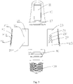
Fig. 3 is an exploded view of a bulb lamp according to an embodiment of the present invention. -
Fig. 4 is a sectional view of a bulb lamp according to an embodiment of the present invention. -
Fig. 5 is a partial enlarged view of a position II inFig. 4 . -
Fig. 6 is a partial enlarged view of a position III inFig. 4 . - Description of names and reference numerals of components in the drawings are provided as follows:
-
Lampshade 10, mounting window 11, limitingsurface 12, pressingsurface 13, guidingslope 14, slot 15,inner cavity 16,mounting end 17,axis 18,light source assembly 20,light source substrate 21,mounting surface 211,light emitting surface 212,light source 22,electrical element 23,lamp holder 30, andinsulating element 40. - To make the purpose, technical solutions and advantages of the present invention clearer, the technical solutions of the present invention are described clearly and completely below in combination with specific embodiments of the present invention and corresponding accompanying drawings. Apparently, the described embodiments are only some embodiments of the present invention, but not all embodiments. All other embodiments obtained by a person of ordinary skill in the art based on the embodiments of the present invention without creative efforts shall fall within the protection scope of the present invention.
- As illustrated by
Fig. 1 , the present embodiment discloses a bulb lamp. The bulb lamp includes alamp holder 30 and a lamp body, the lamp body includes alampshade 10 and alight source assembly 20, and thelampshade 10 is connected with thelamp holder 30. Specifically, referring toFig. 1 andFig. 3 , thelampshade 10 has a mountingend 17, themounting end 17 is an open end, and thelamp holder 30 is connected with themounting end 17. Aninsulating element 40 is arranged between thelamp holder 30 and themounting end 17. Two ends of theinsulating element 40 are open ends, themounting end 17 is inserted into theinsulating element 40 from one open end of theinsulating element 40, and the other end of theinsulating element 40 is connected with thelamp holder 30. A driving power supply is provided in thelamp holder 30. Thelight source assembly 20 includes anelectrical element 23, theelectrical element 23 passes through themounting end 17 to be electrically connected with the driving power supply, and the driving power supply is electrically connected with an external power supply through an electric wire so as to supply power to the whole bulb lamp. - The
light source assembly 20 is integrated on thelampshade 10. In the present embodiment, thelight source assembly 20 is integrated on thelampshade 10, so that a distance between thelight source assembly 20 and the external environment is reduced, and the heat dissipation efficiency is improved. Specifically, thelight source assembly 20 includes alight source substrate 21 and alight source 22 mounted on thelight source substrate 21, and thelight source substrate 21 is integrated on thelampshade 10. - Preferably, a method for integrating the
light source assembly 20 on thelampshade 10 is provided as follows: thelampshade 10 has a mounting window 11, and thelight source substrate 21 is mounted in the mounting window 11, so that thelight source assembly 20 can dissipate the heat directly to the external environment, the heat dissipation efficiency is high, and it is not needed to transfer the heat to thelampshade 10 first and then dissipate the heat to the external environment through thelampshade 10. - The number of the mounting window 11 may be 1, 2, 3, 4, 5, etc. The mounting windows 11 are arranged at intervals along a circumferential direction of the
lampshade 10. Onelight source substrate 21 is provided in each mounting window 11. - The
lampshade 10 is made of a transparent material, and a part of light of thelight source 22 can be irradiated to the external environment through thelampshade 10. Thelight source substrate 21 is a transparent light source substrate, for example, thelight source substrate 21 may be a glass light source substrate. As illustrated byFig. 4 , the surface of thelight source substrate 21 facing aninner cavity 16 of thelampshade 10 is amounting surface 211, an outer surface of thelight source substrate 21 is alight emitting surface 212, thelight source 22 is mounted on themounting surface 211, and the light emitted from thelight source 22 can be irradiated to the external environment through thelight emitting surface 212 of thelight source substrate 21. Thelight source substrate 21 not only can protect thelight source 22, but also can improve the light emitting efficiency of the bulb lamp. In other embodiments, thelight source substrate 21 may also be light-proof, and the light of thelight source 22 can be irradiated to the external environment only through thelampshade 10. - The
light source 22 is attached to themounting surface 211, and the heat of thelight source 22 is transferred directly to thelight source substrate 21, so that the heat transferring efficiency is high. For example, thelight source 22 may be a lamp filament, and the lamp filament is easy to attach to themounting surface 211. - The mounting window 11 may be a rectangular window, and the mounting window 11 has two side walls, one top wall and one bottom wall, a distance between the bottom wall and the
mounting end 17 is shorter than a distance between the top wall and themounting end 17. - The
light source substrate 21 is embedded on thelampshade 10. Specifically, as illustrated byFig. 6 , the bottom wall forms apressing surface 13, and the bottom end surface of thelight source substrate 21 presses thepressing surface 13. Thelampshade 10 includes alimiting surface 12 connected with thepressing surface 13, thelimiting surface 12 is located at an inner side of thepressing surface 13 and forms an angle with thepressing surface 13, and thelimiting surface 12 is in limiting fit with themounting surface 211, so thatlight source substrate 21 can be prevented from moving towards theinner cavity 16. Thelimiting surface 12 may be perpendicular to thepressing surface 13, and may also form an angle greater than 90° or less than 90° with thepressing surface 13. The specific angle may be determined according to an angle of themounting surface 211 with respect to thepressing surface 13. As illustrated byFig. 5 , the top wall of the mounting window 11 has a slot 15, and the top end of thelight source substrate 21 is inserted into the slot 15. - As illustrated by
Fig. 2 andFig. 6 , thelampshade 10 includes a guidingslope 14 connected with thepressing surface 13, and the guidingslope 14 is located at the outer side of thepressing surface 13. One end of the guidingslope 14 is connected with thepressing surface 13, and the other end of the guidingslope 14 faces outward in the radial direction and extends towards the mountingend 17. Thepressing surface 13 is a flat surface, and an angle between the guidingslope 14 and thepressing surface 13 is greater than 90° and less than 180°. - As illustrated by
Fig. 4 , the diameter of thelampshade 10 in a direction away from the mountingend 17 is reduced gradually, which makes the distance between the slot 15 and anaxis 18 of thelampshade 10 shorter than the distance between thepressing surface 13 and theaxis 18 of thelampshade 10, so that when the bottom end of thelight source substrate 21 slides towards the pressingsurface 13 along the guidingslope 14, the top end of thelight source substrate 21 can be inserted into the slot 15 easily, and thelight source substrate 21 is convenient to mount. - The surfaces, except for the mounting
surface 211, light-emittingsurface 212, top end surface and bottom end surface, of thelight source substrate 21 are side surfaces, the top end surface of thelight source substrate 21 is an end surface of an end inserted into the slot 15, and the bottom end surface of thelight source substrate 21 is a surface abutting thepressing surface 13. Two side surfaces of thelight source substrate 21 are spaced to the two side walls of the mounting window 11. - Because the
light source substrate 21 of the present embodiment is mounted in the mounting window 11 of thelampshade 10, thelight source substrate 21 and thelampshade 10 collectively form a lamp cavity, the outer surface of thelight source substrate 21 and the outer surface of thelampshade 10 collectively form an outer surface of the lamp body, and it may also be considered that the outer surface of thelight source substrate 21 is coplanar with the outer surface of thelampshade 10. - The
light source substrate 21 of the present embodiment is very convenient to mount in the mounting window 11, and it is not needed to arrange a connecting member, so that the bulb lamp of the present embodiment has fewer components, and the structure is simple. - In other embodiments, the
lampshade 10 may also be in other shapes, for example, the positions of the slot 15 and pressingsurface 13 may be exchanged, and then the diameter of thelampshade 10 in a direction away from the mountingend 17 is increased gradually. The guidingslope 14 is still connected with thepressing surface 13, the guidingslope 14 is convenient for the top end of thelight source substrate 21 to enter thepressing surface 13, and while the top end of thelight source substrate 21 enters thepressing surface 13, the bottom end of thelight source substrate 21 is inserted into the slot 15. - In other embodiments, the
light source substrate 21 may be mounted in the mounting window 11 in other methods, for example, thelight source substrate 21 may be pasted onto the outer surface or inner surface of thelampshade 10 and block the mounting window 11. Thelight source substrate 21 may also be mounted in the mounting window 11 through the connecting member. - The above description is only embodiments of the present invention and is not used to limit the present invention. For those skilled in the art, various changes and variations of the present invention can be made. Any modifications, equivalent substitution and improvements made within the spirit and principle of the present invention shall fall within the scope of claims of the present invention.
Claims (13)
- A lamp body, comprising a lampshade (10) and a light source assembly (20), wherein the light source assembly (20) is integrated on the lampshade (10).
- The lamp body according to claim 1, wherein the lampshade (10) comprises a mounting window (11), and the light source assembly (20) is mounted in the mounting window (11).
- The lamp body according to claim 2, wherein the light source assembly (20) comprises a light source (22) and a light source substrate (21), which is transparent; a surface of the light source substrate (21) facing an inner cavity (16) of the lampshade (10) is a mounting surface (211), and the light source (22) is mounted on the mounting surface (211).
- The lamp body according to claim 3, wherein the light source substrate (21) is embedded on the lampshade (10).
- The lamp body according to claim 3, wherein at least two light source substrates (21) are provided, and the at least two light source substrates (21) are arranged on the lampshade (10) at intervals.
- The lamp body according to claim 3, wherein the light source (22) is a filament structure, and the light source (22) is attached to the mounting surface (211).
- The lamp body according to claim 2, wherein the light source assembly (20) comprises a light source substrate (21) and a light source (22) mounted on the light source substrate (21), an inner wall of the mounting window (11) forms a pressing surface (13), and an end surface of the light source substrate (21) presses the pressing surface (13).
- The lamp body according to claim 7, wherein the lampshade (10) comprises a limiting surface (12) connected with the pressing surface (13), and the limiting surface (12) is in limiting fit with the mounting surface (211).
- The lamp body according to claim 7, wherein the lampshade (10) comprises a guiding slope (14), one end of the guiding slope (14) is connected with the pressing surface (13), and the other end of the guiding slope (14) inclines outward in a radial direction.
- The lamp body according to claim 7, wherein another inner wall of the mounting window (11) comprises a slot (15), and the other end of the light source substrate (21) is inserted into the slot (15).
- The lamp body according to claim 10, wherein a distance between the slot (15) and an axis (18) of the lampshade (10) is shorter than a distance between the pressing surface (13) and the axis (18).
- A bulb lamp, comprising a lamp holder (30) and the lamp body according to any one of claims 1-11, wherein the lampshade (10) is connected with the lamp holder (30), a driving power supply is provided in the lamp holder (30), and the light source assembly (20) is electrically connected with the driving power supply.
- The bulb lamp according to claim 12, wherein an insulating element (40) is arranged between the lampshade (10) and the lamp holder (30).
Applications Claiming Priority (2)
| Application Number | Priority Date | Filing Date | Title |
|---|---|---|---|
| CN201921546846.XU CN211344826U (en) | 2019-09-17 | 2019-09-17 | Lamp body and bulb |
| PCT/CN2020/111567 WO2021052135A1 (en) | 2019-09-17 | 2020-08-27 | Lamp body and bulb lamp |
Publications (2)
| Publication Number | Publication Date |
|---|---|
| EP3974702A1 true EP3974702A1 (en) | 2022-03-30 |
| EP3974702A4 EP3974702A4 (en) | 2022-05-25 |
Family
ID=72109057
Family Applications (1)
| Application Number | Title | Priority Date | Filing Date |
|---|---|---|---|
| EP20864867.5A Pending EP3974702A4 (en) | 2019-09-17 | 2020-08-27 | LAMP BODY AND BULB LAMP |
Country Status (4)
| Country | Link |
|---|---|
| US (1) | US11781729B2 (en) |
| EP (1) | EP3974702A4 (en) |
| CN (1) | CN211344826U (en) |
| WO (1) | WO2021052135A1 (en) |
Families Citing this family (2)
| Publication number | Priority date | Publication date | Assignee | Title |
|---|---|---|---|---|
| CN211344826U (en) * | 2019-09-17 | 2020-08-25 | 欧普照明股份有限公司 | Lamp body and bulb |
| USD1040378S1 (en) * | 2022-11-14 | 2024-08-27 | Guangdong Jiaduowang Lighting Tech Co., Ltd | Lamp |
Family Cites Families (16)
| Publication number | Priority date | Publication date | Assignee | Title |
|---|---|---|---|---|
| US6716140B2 (en) * | 2002-09-05 | 2004-04-06 | Huan-Yu Cheng | Display for an exercise device |
| JP2006244725A (en) * | 2005-02-28 | 2006-09-14 | Atex Co Ltd | LED lighting device |
| US8186852B2 (en) * | 2009-06-24 | 2012-05-29 | Elumigen Llc | Opto-thermal solution for multi-utility solid state lighting device using conic section geometries |
| WO2014191251A1 (en) * | 2013-05-28 | 2014-12-04 | Koninklijke Philips N.V. | Lighting device and method of manufacturing the same |
| CN203404744U (en) * | 2013-08-01 | 2014-01-22 | 佛山市康荣精细陶瓷有限公司 | Column type wide-angle luminous LED lamp |
| CN203757420U (en) * | 2014-01-25 | 2014-08-06 | 张晓峰 | Novel LED (light-emitting diode) illuminating lamp |
| US9488322B2 (en) * | 2014-04-23 | 2016-11-08 | Cree, Inc. | LED lamp with LED board heat sink |
| CN104654079A (en) * | 2015-01-27 | 2015-05-27 | 浙江英特来光电科技有限公司 | High-performance 360-degree LED (Light-Emitting Diode) lamp |
| US10082269B2 (en) * | 2015-06-08 | 2018-09-25 | Cree, Inc. | LED lamp |
| TW201721053A (en) * | 2015-12-02 | 2017-06-16 | 羅冠傑 | Shell integrated light-emitting diode, assembly and manufacturing method thereof |
| CN106641783A (en) * | 2016-12-30 | 2017-05-10 | 浙江锐迪生光电有限公司 | Zero-thermal-resistance LED filament lamp without core columns and supports |
| CN106678572A (en) * | 2017-01-10 | 2017-05-17 | 佛山电器照明股份有限公司 | Novel LED lamp bulb |
| CN109595480B (en) * | 2017-09-29 | 2020-10-27 | 朗德万斯公司 | CFL pins with a string of light engines |
| US10605412B1 (en) * | 2018-11-16 | 2020-03-31 | Emeryallen, Llc | Miniature integrated omnidirectional LED bulb |
| CN211344826U (en) * | 2019-09-17 | 2020-08-25 | 欧普照明股份有限公司 | Lamp body and bulb |
| US11168879B2 (en) * | 2020-02-28 | 2021-11-09 | Omachron Intellectual Property Inc. | Light source |
-
2019
- 2019-09-17 CN CN201921546846.XU patent/CN211344826U/en active Active
-
2020
- 2020-08-27 EP EP20864867.5A patent/EP3974702A4/en active Pending
- 2020-08-27 WO PCT/CN2020/111567 patent/WO2021052135A1/en not_active Ceased
-
2021
- 2021-12-27 US US17/562,989 patent/US11781729B2/en active Active
Also Published As
| Publication number | Publication date |
|---|---|
| US11781729B2 (en) | 2023-10-10 |
| EP3974702A4 (en) | 2022-05-25 |
| US20220120407A1 (en) | 2022-04-21 |
| WO2021052135A1 (en) | 2021-03-25 |
| CN211344826U (en) | 2020-08-25 |
Similar Documents
| Publication | Publication Date | Title |
|---|---|---|
| KR101375388B1 (en) | Tubular led lighting device | |
| CN101165396A (en) | semiconductor light | |
| US20150354776A1 (en) | Led automobile headlamp | |
| US11781729B2 (en) | Lamp body and bulb lamp | |
| CA2889834C (en) | Light emitting diode spotlight | |
| CN206904679U (en) | A R7s linear light source | |
| WO2019042360A1 (en) | Led lamp | |
| CN203671319U (en) | G4 lamp with LED light source | |
| CN204879505U (en) | Light and ligthing paraphernalia | |
| JP2012044176A (en) | Light-emitting diode lamp | |
| WO2016004723A1 (en) | Omni-directional led lamp | |
| CN224245970U (en) | LED lamp tube | |
| CN205208213U (en) | Can 360 luminous LED R7s light sources | |
| WO2018129858A1 (en) | Novel led bulb | |
| CN202901966U (en) | Light emitting diode (LED) lamp | |
| CN211344825U (en) | Bulb shell structure of LED filament lamp | |
| CN116336439B (en) | LED lamp capable of efficiently radiating | |
| US20210102669A1 (en) | Lighting device, luminaire and manufacturing method | |
| CN206369088U (en) | Low thermal resistance light-emitting device and LED filament lamp | |
| CN203731181U (en) | Straight tube-shaped LED (light-emitting diode) lamp | |
| CN209926049U (en) | Intelligent LED bulb lamp | |
| CN210398439U (en) | LED lamp with high heat dissipation performance | |
| CN209819369U (en) | Tubular ceiling lamp with efficient heat dissipation function | |
| CN209926088U (en) | Waterproof LED spotlight | |
| CN103727435A (en) | G4 lamp with LED light source |
Legal Events
| Date | Code | Title | Description |
|---|---|---|---|
| STAA | Information on the status of an ep patent application or granted ep patent |
Free format text: STATUS: THE INTERNATIONAL PUBLICATION HAS BEEN MADE |
|
| PUAI | Public reference made under article 153(3) epc to a published international application that has entered the european phase |
Free format text: ORIGINAL CODE: 0009012 |
|
| STAA | Information on the status of an ep patent application or granted ep patent |
Free format text: STATUS: REQUEST FOR EXAMINATION WAS MADE |
|
| 17P | Request for examination filed |
Effective date: 20211221 |
|
| AK | Designated contracting states |
Kind code of ref document: A1 Designated state(s): AL AT BE BG CH CY CZ DE DK EE ES FI FR GB GR HR HU IE IS IT LI LT LU LV MC MK MT NL NO PL PT RO RS SE SI SK SM TR |
|
| A4 | Supplementary search report drawn up and despatched |
Effective date: 20220426 |
|
| RIC1 | Information provided on ipc code assigned before grant |
Ipc: F21Y 115/10 20160101ALN20220420BHEP Ipc: F21Y 109/00 20160101ALN20220420BHEP Ipc: F21V 3/02 20060101ALI20220420BHEP Ipc: F21K 9/232 20160101ALI20220420BHEP Ipc: F21V 29/503 20150101ALI20220420BHEP Ipc: F21V 29/10 20150101ALI20220420BHEP Ipc: F21V 19/00 20060101ALI20220420BHEP Ipc: F21K 9/237 20160101AFI20220420BHEP |
|
| DAV | Request for validation of the european patent (deleted) | ||
| DAX | Request for extension of the european patent (deleted) | ||
| STAA | Information on the status of an ep patent application or granted ep patent |
Free format text: STATUS: EXAMINATION IS IN PROGRESS |
|
| 17Q | First examination report despatched |
Effective date: 20240424 |
|
| GRAP | Despatch of communication of intention to grant a patent |
Free format text: ORIGINAL CODE: EPIDOSNIGR1 |
|
| STAA | Information on the status of an ep patent application or granted ep patent |
Free format text: STATUS: GRANT OF PATENT IS INTENDED |
|
| RIC1 | Information provided on ipc code assigned before grant |
Ipc: F21K 9/237 20160101AFI20260312BHEP Ipc: F21V 19/00 20060101ALI20260312BHEP Ipc: F21V 29/10 20150101ALI20260312BHEP Ipc: F21V 29/503 20150101ALI20260312BHEP Ipc: F21K 9/232 20160101ALI20260312BHEP Ipc: F21V 3/02 20060101ALI20260312BHEP Ipc: F21Y 109/00 20160101ALN20260312BHEP Ipc: F21Y 115/10 20160101ALN20260312BHEP |
|
| RIC1 | Information provided on ipc code assigned before grant |
Ipc: F21K 9/237 20160101AFI20260326BHEP Ipc: F21V 19/00 20060101ALI20260326BHEP Ipc: F21V 29/10 20150101ALI20260326BHEP Ipc: F21V 29/503 20150101ALI20260326BHEP Ipc: F21K 9/232 20160101ALI20260326BHEP Ipc: F21V 3/02 20060101ALI20260326BHEP Ipc: F21Y 109/00 20160101ALN20260326BHEP Ipc: F21Y 115/10 20160101ALN20260326BHEP |
|
| INTG | Intention to grant announced |
Effective date: 20260408 |