EP3974653A1 - Centrifugal fan and clothing dryer - Google Patents
Centrifugal fan and clothing dryer Download PDFInfo
- Publication number
- EP3974653A1 EP3974653A1 EP20809669.3A EP20809669A EP3974653A1 EP 3974653 A1 EP3974653 A1 EP 3974653A1 EP 20809669 A EP20809669 A EP 20809669A EP 3974653 A1 EP3974653 A1 EP 3974653A1
- Authority
- EP
- European Patent Office
- Prior art keywords
- air
- impeller
- vanes
- centrifugal fan
- housing
- Prior art date
- Legal status (The legal status is an assumption and is not a legal conclusion. Google has not performed a legal analysis and makes no representation as to the accuracy of the status listed.)
- Pending
Links
- 210000002105 tongue Anatomy 0.000 claims description 121
- 239000010410 layer Substances 0.000 claims description 63
- 239000002356 single layer Substances 0.000 claims description 14
- 238000001035 drying Methods 0.000 description 8
- 230000000694 effects Effects 0.000 description 3
- 238000005381 potential energy Methods 0.000 description 2
- 238000004891 communication Methods 0.000 description 1
- 238000000034 method Methods 0.000 description 1
Images






Classifications
-
- F—MECHANICAL ENGINEERING; LIGHTING; HEATING; WEAPONS; BLASTING
- F04—POSITIVE - DISPLACEMENT MACHINES FOR LIQUIDS; PUMPS FOR LIQUIDS OR ELASTIC FLUIDS
- F04D—NON-POSITIVE-DISPLACEMENT PUMPS
- F04D29/00—Details, component parts, or accessories
- F04D29/40—Casings; Connections of working fluid
- F04D29/42—Casings; Connections of working fluid for radial or helico-centrifugal pumps
- F04D29/4206—Casings; Connections of working fluid for radial or helico-centrifugal pumps especially adapted for elastic fluid pumps
- F04D29/4226—Fan casings
-
- D—TEXTILES; PAPER
- D06—TREATMENT OF TEXTILES OR THE LIKE; LAUNDERING; FLEXIBLE MATERIALS NOT OTHERWISE PROVIDED FOR
- D06F—LAUNDERING, DRYING, IRONING, PRESSING OR FOLDING TEXTILE ARTICLES
- D06F58/00—Domestic laundry dryers
- D06F58/20—General details of domestic laundry dryers
-
- F—MECHANICAL ENGINEERING; LIGHTING; HEATING; WEAPONS; BLASTING
- F04—POSITIVE - DISPLACEMENT MACHINES FOR LIQUIDS; PUMPS FOR LIQUIDS OR ELASTIC FLUIDS
- F04D—NON-POSITIVE-DISPLACEMENT PUMPS
- F04D17/00—Radial-flow pumps, e.g. centrifugal pumps; Helico-centrifugal pumps
- F04D17/08—Centrifugal pumps
- F04D17/16—Centrifugal pumps for displacing without appreciable compression
-
- F—MECHANICAL ENGINEERING; LIGHTING; HEATING; WEAPONS; BLASTING
- F04—POSITIVE - DISPLACEMENT MACHINES FOR LIQUIDS; PUMPS FOR LIQUIDS OR ELASTIC FLUIDS
- F04D—NON-POSITIVE-DISPLACEMENT PUMPS
- F04D25/00—Pumping installations or systems
- F04D25/16—Combinations of two or more pumps ; Producing two or more separate gas flows
- F04D25/166—Combinations of two or more pumps ; Producing two or more separate gas flows using fans
-
- F—MECHANICAL ENGINEERING; LIGHTING; HEATING; WEAPONS; BLASTING
- F04—POSITIVE - DISPLACEMENT MACHINES FOR LIQUIDS; PUMPS FOR LIQUIDS OR ELASTIC FLUIDS
- F04D—NON-POSITIVE-DISPLACEMENT PUMPS
- F04D29/00—Details, component parts, or accessories
- F04D29/26—Rotors specially for elastic fluids
- F04D29/28—Rotors specially for elastic fluids for centrifugal or helico-centrifugal pumps for radial-flow or helico-centrifugal pumps
- F04D29/281—Rotors specially for elastic fluids for centrifugal or helico-centrifugal pumps for radial-flow or helico-centrifugal pumps for fans or blowers
-
- F—MECHANICAL ENGINEERING; LIGHTING; HEATING; WEAPONS; BLASTING
- F04—POSITIVE - DISPLACEMENT MACHINES FOR LIQUIDS; PUMPS FOR LIQUIDS OR ELASTIC FLUIDS
- F04D—NON-POSITIVE-DISPLACEMENT PUMPS
- F04D29/00—Details, component parts, or accessories
- F04D29/26—Rotors specially for elastic fluids
- F04D29/28—Rotors specially for elastic fluids for centrifugal or helico-centrifugal pumps for radial-flow or helico-centrifugal pumps
- F04D29/281—Rotors specially for elastic fluids for centrifugal or helico-centrifugal pumps for radial-flow or helico-centrifugal pumps for fans or blowers
- F04D29/282—Rotors specially for elastic fluids for centrifugal or helico-centrifugal pumps for radial-flow or helico-centrifugal pumps for fans or blowers the leading edge of each vane being substantially parallel to the rotation axis
-
- F—MECHANICAL ENGINEERING; LIGHTING; HEATING; WEAPONS; BLASTING
- F04—POSITIVE - DISPLACEMENT MACHINES FOR LIQUIDS; PUMPS FOR LIQUIDS OR ELASTIC FLUIDS
- F04D—NON-POSITIVE-DISPLACEMENT PUMPS
- F04D29/00—Details, component parts, or accessories
- F04D29/26—Rotors specially for elastic fluids
- F04D29/28—Rotors specially for elastic fluids for centrifugal or helico-centrifugal pumps for radial-flow or helico-centrifugal pumps
- F04D29/30—Vanes
-
- F—MECHANICAL ENGINEERING; LIGHTING; HEATING; WEAPONS; BLASTING
- F04—POSITIVE - DISPLACEMENT MACHINES FOR LIQUIDS; PUMPS FOR LIQUIDS OR ELASTIC FLUIDS
- F04D—NON-POSITIVE-DISPLACEMENT PUMPS
- F04D29/00—Details, component parts, or accessories
- F04D29/40—Casings; Connections of working fluid
- F04D29/42—Casings; Connections of working fluid for radial or helico-centrifugal pumps
- F04D29/4206—Casings; Connections of working fluid for radial or helico-centrifugal pumps especially adapted for elastic fluid pumps
- F04D29/422—Discharge tongues
-
- F—MECHANICAL ENGINEERING; LIGHTING; HEATING; WEAPONS; BLASTING
- F04—POSITIVE - DISPLACEMENT MACHINES FOR LIQUIDS; PUMPS FOR LIQUIDS OR ELASTIC FLUIDS
- F04D—NON-POSITIVE-DISPLACEMENT PUMPS
- F04D29/00—Details, component parts, or accessories
- F04D29/40—Casings; Connections of working fluid
- F04D29/42—Casings; Connections of working fluid for radial or helico-centrifugal pumps
- F04D29/4206—Casings; Connections of working fluid for radial or helico-centrifugal pumps especially adapted for elastic fluid pumps
- F04D29/4226—Fan casings
- F04D29/424—Double entry casings
-
- F—MECHANICAL ENGINEERING; LIGHTING; HEATING; WEAPONS; BLASTING
- F04—POSITIVE - DISPLACEMENT MACHINES FOR LIQUIDS; PUMPS FOR LIQUIDS OR ELASTIC FLUIDS
- F04D—NON-POSITIVE-DISPLACEMENT PUMPS
- F04D29/00—Details, component parts, or accessories
- F04D29/40—Casings; Connections of working fluid
- F04D29/42—Casings; Connections of working fluid for radial or helico-centrifugal pumps
- F04D29/44—Fluid-guiding means, e.g. diffusers
- F04D29/441—Fluid-guiding means, e.g. diffusers especially adapted for elastic fluid pumps
-
- F—MECHANICAL ENGINEERING; LIGHTING; HEATING; WEAPONS; BLASTING
- F04—POSITIVE - DISPLACEMENT MACHINES FOR LIQUIDS; PUMPS FOR LIQUIDS OR ELASTIC FLUIDS
- F04D—NON-POSITIVE-DISPLACEMENT PUMPS
- F04D29/00—Details, component parts, or accessories
- F04D29/40—Casings; Connections of working fluid
- F04D29/42—Casings; Connections of working fluid for radial or helico-centrifugal pumps
- F04D29/44—Fluid-guiding means, e.g. diffusers
- F04D29/46—Fluid-guiding means, e.g. diffusers adjustable
- F04D29/48—Fluid-guiding means, e.g. diffusers adjustable for unidirectional fluid flow in reversible pumps
- F04D29/483—Fluid-guiding means, e.g. diffusers adjustable for unidirectional fluid flow in reversible pumps especially adapted for elastic fluid pumps
Definitions
- the present disclosure belongs to the technical field of fans, and specifically provides a centrifugal fan and a dryer.
- a centrifugal fan uses a high-speed rotating impeller to accelerate gas, then decelerate it, and change a flow direction thereof, thus converting kinetic energy into potential energy.
- the centrifugal fan includes a motor, a housing, and an impeller arranged in the housing.
- the motor can drive the impeller to rotate at a high speed to accelerate the gas.
- a volute tongue is provided at an air outlet of the housing, and the volute tongue can cut an air flow driven by the impeller so that the air flow is discharged from the air outlet.
- the centrifugal fan is required to be able to achieve both forward and reverse rotations.
- existing dryers usually use one motor to simultaneously drive a drying cylinder and the impeller of the centrifugal fan to rotate.
- the drying cylinder needs to rotate in both forward and reverse directions during the working process of the dryer.
- the impeller rotates in the forward direction as the drying cylinder rotates in the forward direction (which is the design direction of the centrifugal fan)
- the volute tongue can cut the air flow driven by the impeller so that the air flow is discharged from the air outlet.
- the present disclosure provides a centrifugal fan, which includes a housing, as well as an impeller and volute tongues that are arranged in the housing, in which the housing is provided with an air inlet and an air outlet, the volute tongues include a first volute tongue and a second volute tongue that are stacked and offset from each other, and the impeller is arranged to be capable of suctioning air into the housing from the air inlet when rotating; the first volute tongue is arranged to be capable of cutting the air blown from the impeller and guiding the air to the air outlet when the impeller is rotating in a forward direction, and the second volute tongue is arranged to be capable of cutting the air blown from the impeller and guiding the air
- the impeller is a double-layer impeller which includes a first-layer impeller portion corresponding to the first volute tongue and a second-layer impeller portion corresponding to the second volute tongue, an axis of the first-layer impeller portion coinciding with an axis of the second-layer impeller portion.
- the first-layer impeller portion includes a plurality of first vanes arranged annularly, which are collectively arranged to be capable of guiding air entering the housing from the air inlet to the first volute tongue when the first-layer impeller portion is rotating in the forward direction; and the second-layer impeller portion includes a plurality of second vanes arranged annularly, which are collectively arranged to be capable of guiding the air entering the housing from the air inlet to the second volute tongue when the second-layer impeller portion is rotating in the reverse direction.
- the first vanes and the second vanes are all arc-shaped vanes, and an inclination direction of the first vanes is different from an inclination direction of the second vanes.
- the first vanes and the second vanes are all straight vanes, and an inclination direction of the first vanes is the same as or different from an inclination direction of the second vanes.
- the impeller is a single-layer impeller which includes an impeller portion corresponding to the first volute tongue and the second volute tongue, and the impeller portion includes a plurality of vanes arranged annularly, which are collectively arranged to be capable of guiding air entering the housing from the air inlet to the first volute tongue and the second volute tongue when the impeller portion rotates either in the forward direction or in the reverse direction.
- the plurality of vanes are all straight vanes and arranged in a radial direction of the single-layer impeller.
- the number of the air inlet is one, and the air inlet is provided on one side of the housing.
- an air guiding structure is provided in the impeller, and the air guiding structure is arranged to be capable of guiding the air entering the housing.
- the air guiding structure is an air guiding frustum, and a cone end of the air guiding frustum is arranged close to the air inlet.
- the number of the air inlet is two, and the air inlets include a first air inlet and a second air inlet which are respectively arranged on both sides of the housing.
- an air guiding structure is provided in the impeller, and the air guiding structure is arranged to be capable of guiding the air entering the housing.
- the air guiding structure includes a first air guiding frustum and a second air guiding frustum that are connected, in which a cone end of the first air guiding frustum is arranged close to the first air inlet, and a cone end of the second air guiding frustum is arranged close to the second air inlet.
- the present disclosure also provides a dryer, which includes the centrifugal fan described above.
- two volute tongue structures are provided in the housing of the centrifugal fan: a first volute tongue and a second volute tongue, and the first volute tongue and the second volute tongue are stacked and offset from each other.
- the first volute tongue is arranged on a left-side plate of the housing and close to a top plate of the housing
- the second volute tongue is arranged on a right-side plate of the housing and close to a bottom plate of the housing.
- the centrifugal fan can blow out a large amount of air when the impeller rotates either in the forward direction or in the reverse direction.
- the impeller is a double-layer impeller.
- the double-layer impeller includes a first-layer impeller portion and a second-layer impeller portion.
- the first-layer impeller portion corresponds to the first volute tongue
- the second-layer impeller portion corresponds to the second volute tongue.
- the first vanes can guide the air entering the housing from the air inlet to the first volute tongue, which can therefore increase the air volume discharged from the centrifugal fan.
- the second vanes can guide the air entering the housing from the air inlet to the second volute tongue, which can therefore increase the air volume discharged from the centrifugal fan. That is, the air volume discharged from the centrifugal fan can be increased when the impeller rotates either in the forward direction or in the reverse direction.
- the impeller is a single-layer impeller which includes an impeller portion corresponding to the first volute tongue and the second volute tongue, and the impeller portion includes a plurality of vanes arranged annularly.
- the plurality of vanes are all straight vanes and arranged in the radial direction of the single-layer impeller.
- the centrifugal fan can blow out the same amount of air when the impeller rotates either in the forward direction or in the reverse direction.
- an air guiding structure is provided in the impeller.
- the air guiding structure guides the air entering the housing, which is advantageous for the flow of air.
- the air inlet includes a first air inlet and a second air inlet, which are respectively provided on both sides of the housing.
- the air guiding structure includes a first air guiding frustum and a second air guiding frustum that are connected, with a cone end of the first air guiding frustum being arranged close to the first air inlet, and a cone end of the second air guiding frustum being arranged close to the second air inlet.
- the first air guiding frustum guides the air entering from the first air inlet
- the second air guiding frustum guides the air entering from the second air inlet, which can avoid air collision and turbulence in the impeller.
- the first air guiding frustum guides the air entering from the first air inlet to the first impeller portion
- the second air guiding frustum guides the air entering from the second air inlet to the second impeller portion, which can avoid air collision in the impeller.
- the first air guiding frustum guides the air entering from the first air inlet to the upper half of the impeller portion
- the second air guiding frustum guides the air entering from the second air inlet to the lower half of the impeller portion, which can avoid air collision in the impeller.
- the dryer further provided by the present disclosure on the basis of the above technical solutions due to the employment of the above centrifugal fan, has the technical effects of the above centrifugal fan.
- the dryer of the present disclosure can provide a sufficient amount of air when the drying cylinder rotates either in the forward direction or in the reverse direction, thereby improving the drying effect on the clothing.
- connection may be a fixed connection, or may also be a detachable connection, or an integral connection; it may be a mechanical connection, or an electrical connection; it may be a direct connection, or an indirect connection implemented through an intermediate medium, or it may be an internal communication between two elements.
- connection may be a fixed connection, or may also be a detachable connection, or an integral connection; it may be a mechanical connection, or an electrical connection; it may be a direct connection, or an indirect connection implemented through an intermediate medium, or it may be an internal communication between two elements.
- the present disclosure provides a centrifugal fan and a dryer, aiming at enabling the volute tongue of the centrifugal fan to cut the air flow driven by the impeller when the impeller rotates either in the forward direction or in the reverse direction and guaranteeing the demand on the air volume.
- the centrifugal fan of the present disclosure includes a housing, as well as an impeller and volute tongues that are arranged in the housing, in which the housing is provided with an air inlet and an air outlet, the volute tongues include a first volute tongue and a second volute tongue that are stacked and offset from each other, and the impeller is arranged to be capable of suctioning air into the housing from the air inlet when rotating; the first volute tongue is arranged to be capable of cutting the air blown from the impeller and guiding the air to the air outlet when the impeller is rotating in a forward direction, and the second volute tongue is arranged to be capable of cutting the air blown from the impeller and guiding the air to the air outlet when the impeller is rotating in a reverse direction.
- two volute tongue structures are provided in the housing of the centrifugal fan: a first volute tongue and a second volute tongue, and the first volute tongue and the second volute tongue are arranged in a layered and staggered manner.
- the first volute tongue is arranged on a left-side plate of the housing and close to a top plate of the housing
- the second volute tongue is arranged on a right-side plate of the housing and close to a bottom plate of the housing.
- the centrifugal fan can blow out a large amount of air when the impeller rotates either in the forward direction or in the reverse direction.
- FIG. 1 is a first schematic structural view of the first embodiment of the centrifugal fan of the present disclosure
- FIG. 2 is a second schematic structural view of the first embodiment of the centrifugal fan of the present disclosure
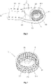
- FIG. 3 is a first schematic structural view of an impeller of the first embodiment of the centrifugal fan of the present disclosure
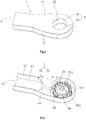
- FIG. 4 is a third schematic structural view of the first embodiment of the centrifugal fan of the present disclosure
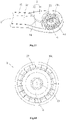
- FIG. 5 is a second schematic structural view of the impeller of the first embodiment of the centrifugal fan of the present disclosure.
- the centrifugal fan of this embodiment includes a housing 1, as well as an impeller 2 and volute tongues 3 that are arranged in the housing 1.
- the housing 1 is provided with an air inlet 4 and an air outlet 5.
- the volute tongues 3 include a first volute tongue 31 and a second volute tongue 32 that are stacked and offset from each other.
- the impeller 2 is a double-layer impeller which includes a first-layer impeller portion 21 corresponding to the first volute tongue 31 and a second-layer impeller portion 22 corresponding to the second volute tongue 32, an axis of the first-layer impeller portion 21 coinciding with an axis of the second-layer impeller portion 22.
- the number of the air inlet 4 is one, and the air inlet 4 is arranged on a top plate 11 of the housing 1. Of course, the air inlet 4 may also be arranged on a bottom plate 12 of the housing 1.
- the first volute tongue 31 is arranged at an upper part of a left-side plate 13 of the housing 1, that is, arranged close to the top plate 11, and the second volute tongue 32 is arranged at a lower part of a right-side plate 14 of the housing 1, that is, arranged close to the bottom plate 12.
- the first volute tongue 31 can cut the air blown from the first-layer impeller portion 21 and guide the air to the air outlet 5
- the second volute tongue 32 can cut the air blown from the second-layer impeller portion 22 and guide the air to the air outlet 5.
- the first-layer impeller portion 21 includes a plurality of first vanes 211 arranged annularly, which are collectively arranged to be capable of guiding the air entering the housing 1 from the air inlet 4 to the first volute tongue 31 when the first-layer impeller portion 21 is rotating in the forward direction; and the second-layer impeller portion 22 includes a plurality of second vanes 221 arranged annularly, which are collectively arranged to be capable of guiding the air entering the housing 1 from the air inlet 4 to the second volute tongue 32 when the second-layer impeller portion 22 is rotating in the reverse direction.
- first vanes 211 arranged annularly, which are collectively arranged to be capable of guiding the air entering the housing 1 from the air inlet 4 to the first volute tongue 31 when the first-layer impeller portion 21 is rotating in the forward direction
- the second-layer impeller portion 22 includes a plurality of second vanes 221 arranged annularly, which are collectively arranged to be capable of guiding the air entering the housing 1 from the air inlet
- the first vanes 211 and the second vanes 221 are all arc-shaped vanes.
- the first-layer impeller portion 21 rotates in the forward direction (rotating clockwise when viewed from the figure)
- the first vanes 211 can guide the air entering the housing 1 from the air inlet 4 to the first volute tongue 31.
- the second-layer impeller portion 22 rotates in the reverse direction (rotating counterclockwise when viewed from the figure)
- the second vanes 221 are inclined counterclockwise, the second vanes 221 can guide the air entering the housing 1 from the air inlet 4 to the second volute tongue 32.
- An inclination direction of the first vanes 211 is different from an inclination direction of the second vanes 221.
- the first vanes 211 and the second vanes 221 are all straight vanes.
- the second vanes 221 can guide the air entering the housing 1 from the air inlet 4 to the second volute tongue 32.
- the inclination direction of the first vanes 211 is different from the inclination direction of the second vanes 221.
- the first vanes 211 and the second vanes 221 are all straight vanes, and the first vanes 211 and the second vanes 221 are all arranged in the radial direction of the impeller 2.
- the inclination direction of the first vanes 211 is the same as the inclination direction of the second vanes 221.
- first vanes 211 and the second vanes 221 may also be configured into other shapes.
- first vanes 211 and the second vanes 221 may also be provided as "V"-shaped vanes or "L"-shaped vanes, etc.
- an air guiding structure 6 is provided in the impeller 2, and the air guiding structure 6 is arranged to be capable of guiding the air entering the housing 1.
- the air guiding structure 6 is an air guiding frustum 6, and a cone end 61 of the air guiding frustum 6 is arranged close to the air inlet 4.
- the air enters from the air inlet 4 and then flows to the first-layer impeller portion 21 and the second-layer impeller portion 22 under the guidance of the air guiding frustum 6.
- the air guiding structure 6 may also be provided as other air guiding structures such as a triangular pyramid. Such adjustments and changes to the specific structural form of the air guiding structure 6 do not deviate from the principle and scope of the present disclosure, and should be defined within the scope of protection of the present disclosure.
- FIG. 6 is a schematic structural view of a housing of the second embodiment of the centrifugal fan of the present disclosure
- FIG. 7 is a first schematic structural view of the second embodiment of the centrifugal fan of the present disclosure
- FIG. 8 is a second schematic structural view of the second embodiment of the centrifugal fan of the present disclosure
- FIG. 9 is a third schematic structural view of the second embodiment of the centrifugal fan of the present disclosure
- FIG. 10 is a schematic structural view of the impeller of the second embodiment of the centrifugal fan of the present disclosure
- FIG. 11 is a cross-sectional view of FIG. 10 .
- the centrifugal fan of this embodiment includes a housing 1, as well as an impeller 2 and volute tongues 3 that are arranged in the housing 1.
- the housing 1 is provided with air inlets 4 and an air outlet 5.
- the volute tongues 3 include a first volute tongue 31 and a second volute tongue 32 that are stacked and offset from each other.
- the impeller 2 is a double-layer impeller which includes a first-layer impeller portion 21 corresponding to the first volute tongue 31 and a second-layer impeller portion 22 corresponding to the second volute tongue 32, an axis of the first-layer impeller portion 21 coinciding with an axis of the second-layer impeller portion 22.
- the number of the air inlets 4 is two, and the air inlets 4 include a first air inlet 41 and a second air inlet 42.
- the first air inlet 41 and the second air inlet 42 are respectively provided on both sides of the housing 1, the first air inlet 41 may be provided on the top plate 11 of the housing 1, and the second air inlet 42 may be provided on the bottom plate 12 of the housing 1.
- the first volute tongue 31 is arranged at an upper part of the left-side plate 13 of the housing 1, that is, arranged close to the top plate 11, and the second volute tongue 32 is arranged at a lower part of the right-side plate 14 of the housing 1, that is, arranged close to the bottom plate 12.
- the first volute tongue 31 can cut the air blown from the first-layer impeller portion 21 and guide the air to the air outlet 5
- the second volute tongue 32 can cut the air blown from the second-layer impeller portion 22 and guide the air to the air outlet 5.
- an output shaft of a driving motor (not shown in the figure) used to drive the impeller 2 to rotate may extend from the first air inlet 41 or the second air inlet 42 so as to be connected connect with the impeller 2. If the output shaft of the driving motor extends from the first air inlet 41, it is necessary to set a gap between the driving motor and the first air inlet 41 to avoid impeding the air from entering the housing 1 from the first air inlet 41. Similarly, if the output shaft of the driving motor extends from the second air inlet 42, it is necessary to set a gap between the driving motor and the second air inlet 42 to avoid impeding the air from entering the housing 1 from the second air inlet 42.
- the first-layer impeller portion 21 includes a plurality of first vanes 211 arranged annularly, which are collectively arranged to be capable of guiding the air entering the housing 1 from the air inlet 4 to the first volute tongue 31 when the first-layer impeller portion 21 is rotating in the forward direction; and the second-layer impeller portion 22 includes a plurality of second vanes 221 arranged annularly, which are collectively arranged to be capable of guiding the air entering the housing 1 from the air inlet 4 to the second volute tongue 32 when the second-layer impeller portion 22 is rotating in the reverse direction.
- first vanes 211 arranged annularly, which are collectively arranged to be capable of guiding the air entering the housing 1 from the air inlet 4 to the first volute tongue 31 when the first-layer impeller portion 21 is rotating in the forward direction
- the second-layer impeller portion 22 includes a plurality of second vanes 221 arranged annularly, which are collectively arranged to be capable of guiding the air entering the housing 1 from the air inlet
- the first vanes 211 and the second vanes 221 are all arc-shaped vanes.
- the first-layer impeller portion 21 rotates in the forward direction (rotating clockwise when viewed from the figure)
- the first vanes 211 can guide the air entering the housing 1 from the air inlet 4 to the first volute tongue 31.
- the second-layer impeller portion 22 rotates in the reverse direction (rotating counterclockwise when viewed from the figure)
- the second vanes 221 are inclined counterclockwise
- the second vanes 221 can guide the air entering the housing 1 from the air inlet 4 to the second volute tongue 32.
- An inclination direction of the first vanes 211 is different from an inclination direction of the second vanes 221.
- the first vanes 211 and the second vanes 221 are all straight vanes.
- the first-layer impeller portion 21 rotates in the forward direction (rotating clockwise when viewed from the figure)
- the first vanes 211 can guide the air entering the housing 1 from the air inlet 4 to the first volute tongue 31.
- the second-layer impeller portion 22 rotates in the reverse direction (rotating counterclockwise when viewed from the figure)
- the second vanes 221 since the second vanes 221 are inclined counterclockwise, the second vanes 221 can guide the air entering the housing 1 from the air inlet 4 to the second volute tongue 32.
- the inclination direction of the first vanes 211 is different from the inclination direction of the second vanes 221.
- the first vanes 211 and the second vanes 221 are all straight vanes, and the first vanes 211 and the second vanes 221 are all arranged in the radial direction of the impeller 2.
- the inclination direction of the first vanes 211 is the same as the inclination direction of the second vanes 221. It should be noted that these above several situations are only preferred situations.
- the first vanes 211 and the second vanes 221 may also be configured into other shapes.
- first vanes 211 and the second vanes 221 may also be provided as "V"-shaped vanes or "L”-shaped vanes, etc.
- V vane-shaped vanes
- L vane-shaped vanes
- an air guiding structure 6 is provided in the impeller 2, and the air guiding structure 6 is arranged to be capable of guiding the air entering the housing 1.
- the air guiding structure 6 includes a first air guiding frustum 6A and a second air guiding frustum 6B that are connected, with a cone end 6A1 of the first air guiding frustum 6A being arranged close to the first air inlet 41, and a cone end 6B1 of the second air guiding frustum 6B being arranged close to the second air inlet 42.
- the air enters from the first air inlet 41 and then flows to the first-layer impeller portion 21 under the guidance of the first air guiding frustum 6A, and the air enters from the second air inlet 42 and then flows to the second-layer impeller portion 22 under the guidance of the second air guiding frustum 6B.
- the air guiding structure 6 may also be provided as other air guiding structures such as two triangular pyramids connected. Such adjustments and changes to the specific structural form of the air guiding structure 6 do not deviate from the principle and scope of the present disclosure, and should be defined within the scope of protection of the present disclosure.
- FIG. 12 is a first schematic structural view of the third embodiment of the centrifugal fan of the present disclosure
- FIG. 13 is a second schematic structural view of the third embodiment of the centrifugal fan of the present disclosure
- FIG. 14 is a first schematic structural view of the impeller of the third embodiment of the centrifugal fan of the present disclosure
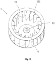
- FIG. 15 is a second schematic structural view of the impeller of the third embodiment of the centrifugal fan of the present disclosure.
- the centrifugal fan of this embodiment includes a housing 1, as well as an impeller 2 and volute tongues 3 that are arranged in the housing 1.
- the housing 1 is provided with an air inlet 4 and an air outlet 5.
- the volute tongues 3 include a first volute tongue 31 and a second volute tongue 32 that are stacked and offset from each other.
- the impeller 2 is a single-layer impeller which includes an impeller portion 23 corresponding to the first volute tongue 31 and the second volute tongue 32, and the impeller portion 23 includes a plurality of vanes 231 arranged annularly, which are collectively arranged to be capable of guiding air entering the housing 1 from the air inlet 4 to the first volute tongue 31 and the second volute tongue 32 when the impeller portion 23 rotates either in the forward direction or in the reverse direction.
- the air inlet 4 is arranged on the top plate 11 of the housing 1. Of course, the air inlet 4 may also be arranged on the bottom plate 12 of the housing 1.
- the first volute tongue 31 is arranged at an upper part of the left-side plate 13 of the housing 1, that is, arranged close to the top plate 11, and the second volute tongue 32 is arranged at a lower part of the right-side plate 14 of the housing 1, that is, arranged close to the bottom plate 12.
- the first volute tongue 31 can cut the air blown from an upper half of the impeller portion 23 and guide the air to the air outlet 5
- the second volute tongue 32 can cut the air blown from a lower half of the impeller portion 23 and guide the air to the air outlet 5.
- the plurality of vanes 231 are all straight vanes and are arranged in the radial direction of the single-layer impeller.
- the centrifugal fan can blow out the same amount of air when the impeller 2 rotates either in the forward direction or in the reverse direction.
- the vanes 231 may also be set to form a specific angle with the radial direction of the single-layer impeller, or the vanes 231 may be configured into other shapes.
- the vanes 231 may be provided as arc-shaped vanes (just as shown in FIG. 15 ), "V"-shaped vanes or “L”-shaped vanes, etc.
- Such flexible adjustments and changes do not deviate from the principle and scope of the present disclosure, and should be defined within the scope of protection of the present disclosure.
- an air guiding structure 6 is provided in the impeller 2, and the air guiding structure 6 is arranged to be capable of guiding the air entering the housing 1.
- the air guiding structure 6 is an air guiding frustum 6, and a cone end 61 of the air guiding frustum 6 is arranged close to the air inlet 4. The air enters from the air inlet 4 and then flows to the impeller portion 23 under the guidance of the air guiding frustum 6.
- the air guiding structure 6 may also be provided as other air guiding structures such as a triangular pyramid. Such adjustments and changes to the specific structural form of the air guiding structure 6 do not deviate from the principle and scope of the present disclosure, and should be defined within the scope of protection of the present disclosure.
- FIG. 16 is a first schematic structural view of the fourth embodiment of the centrifugal fan of the present disclosure
- FIG. 17 is a second schematic structural view of the fourth embodiment of the centrifugal fan of the present disclosure
- FIG. 18 is a schematic structural view of the impeller of the fourth embodiment of the centrifugal fan of the present disclosure
- FIG. 19 is a cross-sectional view of FIG. 18 .
- the centrifugal fan of this embodiment includes a housing 1, as well as an impeller 2 and volute tongues 3 that are arranged in the housing 1.
- the housing 1 is provided with air inlets 4 and an air outlet 5.
- the volute tongues 3 include a first volute tongue 31 and a second volute tongue 32 that are stacked and offset from each other.
- the impeller 2 is a single-layer impeller which includes an impeller portion 23 corresponding to the first volute tongue 31 and the second volute tongue 32, and the impeller portion 23 includes a plurality of vanes 231 arranged annularly, which are collectively arranged to be capable of guiding air entering the housing 1 from the air inlets 4 to the first volute tongue 31 and the second volute tongue 32 when the impeller portion 23 rotates either in the forward direction or in the reverse direction.
- the number of the air inlets 4 is two, and the air inlets 4 include a first air inlet 41 and a second air inlet (not shown in the figures).
- the first air inlet 41 and the second air inlet are respectively provided on both sides of the housing 1, the first air inlet 41 may be provided on the top plate 11 of the housing 1, and the second air inlet may be provided on the bottom plate 12 of the housing 1.
- the first volute tongue 31 is arranged at an upper part of the left-side plate 13 of the housing 1, that is, arranged close to the top plate 11, and the second volute tongue 32 is arranged at a lower part of the right-side plate 14 of the housing 1, that is, arranged close to the bottom plate 12.
- the first volute tongue 31 can cut the air blown from an upper half of the impeller portion 23 and guide the air to the air outlet 5, and when the impeller 2 is rotating in the reverse direction (rotating counterclockwise when viewed from the figure), the second volute tongue 32 can cut the air blown from a lower half of the impeller portion 23 and guide the air to the air outlet 5.
- an output shaft of a driving motor (not shown in the figure) used to drive the impeller 2 to rotate may extend from the first air inlet 41 or the second air inlet so as to be connected connect with the impeller 2. If the output shaft of the driving motor extends from the first air inlet 41, it is necessary to set a gap between the driving motor and the first air inlet 41 to avoid impeding the air from entering the housing 1 from the first air inlet 41. Similarly, if the output shaft of the driving motor extends from the second air inlet, it is necessary to set a gap between the driving motor and the second air inlet to avoid impeding the air from entering the housing 1 from the second air inlet.
- the plurality of vanes 231 are all straight vanes and are arranged in the radial direction of the single-layer impeller.
- the centrifugal fan can blow out the same amount of air when the impeller 2 rotates either in the forward direction or in the reverse direction.
- the vanes 231 may also be set to form a specific angle with the radial direction of the single-layer impeller, or the vanes 231 may be configured into other shapes.
- the vanes 231 may be provided as arc-shaped vanes, "V"-shaped vanes or "L”-shaped vanes, etc. Such flexible adjustments and changes do not deviate from the principle and scope of the present disclosure, and should be defined within the scope of protection of the present disclosure.
- an air guiding structure 6 is provided in the impeller 2, and the air guiding structure 6 is arranged to be capable of guiding the air entering the housing 1.
- the air guiding structure 6 includes a first air guiding frustum 6A and a second air guiding frustum 6B that are connected, with a cone end 6A1 of the first air guiding frustum 6A being arranged close to the first air inlet 41, and a cone end 6B1 of the second air guiding frustum 6B being arranged close to the second air inlet 42.
- the air enters from the first air inlet 41 and then flows to an upper half of the impeller portion 23 under the guidance of the first air guiding frustum 6A, and the air enters from the second air inlet and then flows to a lower half of the impeller portion 23 under the guidance of the second air guiding frustum 6B.
- the air guiding structure 6 may also be provided as other air guiding structures such as two triangular pyramids connected. Such adjustments and changes to the specific structural form of the air guiding structure 6 do not deviate from the principle and scope of the present disclosure, and should be defined within the scope of protection of the present disclosure.
- the present disclosure also provides a dryer, which includes the centrifugal fan of the first embodiment, the second embodiment, the third embodiment or the fourth embodiment.
Landscapes
- Engineering & Computer Science (AREA)
- Mechanical Engineering (AREA)
- General Engineering & Computer Science (AREA)
- Textile Engineering (AREA)
- Physics & Mathematics (AREA)
- Fluid Mechanics (AREA)
- Structures Of Non-Positive Displacement Pumps (AREA)
Abstract
Description
- The present disclosure belongs to the technical field of fans, and specifically provides a centrifugal fan and a dryer.
- Based on the principle of converting kinetic energy into potential energy, a centrifugal fan uses a high-speed rotating impeller to accelerate gas, then decelerate it, and change a flow direction thereof, thus converting kinetic energy into potential energy. The centrifugal fan includes a motor, a housing, and an impeller arranged in the housing. The motor can drive the impeller to rotate at a high speed to accelerate the gas. A volute tongue is provided at an air outlet of the housing, and the volute tongue can cut an air flow driven by the impeller so that the air flow is discharged from the air outlet.
- In some occasions, the centrifugal fan is required to be able to achieve both forward and reverse rotations. Taking dryers as an example, in order to reduce the cost, existing dryers usually use one motor to simultaneously drive a drying cylinder and the impeller of the centrifugal fan to rotate. In order to solve the problem of entangled clothing in the drying cylinder, the drying cylinder needs to rotate in both forward and reverse directions during the working process of the dryer. When the impeller rotates in the forward direction as the drying cylinder rotates in the forward direction (which is the design direction of the centrifugal fan), the volute tongue can cut the air flow driven by the impeller so that the air flow is discharged from the air outlet. However, when the impeller rotates in the reverse direction as the drying cylinder rotates in the reverse direction (which is opposite to the design direction), the volute tongue cannot cut the air flow driven by the impeller, resulting in a sharp decrease in the air volume discharged from the air outlet, thereby affecting a drying effect on the clothing.
- Accordingly, there is a need in the art for a new centrifugal fan and dryer to solve the above problem.
- In order to solve the above problem in the prior art, that is, to solve the problem that the volute tongue of the existing centrifugal fan cannot cut the air flow driven by the impeller when the rotation direction of the impeller is opposite to the design direction, which results in a sharp decrease in the air volume discharged from the centrifugal fan, the present disclosure provides a centrifugal fan, which includes a housing, as well as an impeller and volute tongues that are arranged in the housing, in which the housing is provided with an air inlet and an air outlet, the volute tongues include a first volute tongue and a second volute tongue that are stacked and offset from each other, and the impeller is arranged to be capable of suctioning air into the housing from the air inlet when rotating; the first volute tongue is arranged to be capable of cutting the air blown from the impeller and guiding the air to the air outlet when the impeller is rotating in a forward direction, and the second volute tongue is arranged to be capable of cutting the air blown from the impeller and guiding the air to the air outlet when the impeller is rotating in a reverse direction.
- In a preferred technical solution of the above centrifugal fan, the impeller is a double-layer impeller which includes a first-layer impeller portion corresponding to the first volute tongue and a second-layer impeller portion corresponding to the second volute tongue, an axis of the first-layer impeller portion coinciding with an axis of the second-layer impeller portion.
- In a preferred technical solution of the above centrifugal fan, the first-layer impeller portion includes a plurality of first vanes arranged annularly, which are collectively arranged to be capable of guiding air entering the housing from the air inlet to the first volute tongue when the first-layer impeller portion is rotating in the forward direction; and the second-layer impeller portion includes a plurality of second vanes arranged annularly, which are collectively arranged to be capable of guiding the air entering the housing from the air inlet to the second volute tongue when the second-layer impeller portion is rotating in the reverse direction.
- In a preferred technical solution of the above centrifugal fan, the first vanes and the second vanes are all arc-shaped vanes, and an inclination direction of the first vanes is different from an inclination direction of the second vanes.
- In a preferred technical solution of the above centrifugal fan, the first vanes and the second vanes are all straight vanes, and an inclination direction of the first vanes is the same as or different from an inclination direction of the second vanes.
- In a preferred technical solution of the above centrifugal fan, the impeller is a single-layer impeller which includes an impeller portion corresponding to the first volute tongue and the second volute tongue, and the impeller portion includes a plurality of vanes arranged annularly, which are collectively arranged to be capable of guiding air entering the housing from the air inlet to the first volute tongue and the second volute tongue when the impeller portion rotates either in the forward direction or in the reverse direction.
- In a preferred technical solution of the above centrifugal fan, the plurality of vanes are all straight vanes and arranged in a radial direction of the single-layer impeller.
- In a preferred technical solution of the above centrifugal fan, the number of the air inlet is one, and the air inlet is provided on one side of the housing.
- In a preferred technical solution of the above centrifugal fan, an air guiding structure is provided in the impeller, and the air guiding structure is arranged to be capable of guiding the air entering the housing.
- In a preferred technical solution of the above centrifugal fan, the air guiding structure is an air guiding frustum, and a cone end of the air guiding frustum is arranged close to the air inlet.
- In a preferred technical solution of the above centrifugal fan, the number of the air inlet is two, and the air inlets include a first air inlet and a second air inlet which are respectively arranged on both sides of the housing.
- In a preferred technical solution of the above centrifugal fan, an air guiding structure is provided in the impeller, and the air guiding structure is arranged to be capable of guiding the air entering the housing.
- In a preferred technical solution of the above centrifugal fan, the air guiding structure includes a first air guiding frustum and a second air guiding frustum that are connected, in which a cone end of the first air guiding frustum is arranged close to the first air inlet, and a cone end of the second air guiding frustum is arranged close to the second air inlet.
- In another aspect, the present disclosure also provides a dryer, which includes the centrifugal fan described above.
- It can be understood by those skilled in the art that in the preferred technical solutions of the present disclosure, two volute tongue structures are provided in the housing of the centrifugal fan: a first volute tongue and a second volute tongue, and the first volute tongue and the second volute tongue are stacked and offset from each other. For example, the first volute tongue is arranged on a left-side plate of the housing and close to a top plate of the housing, and the second volute tongue is arranged on a right-side plate of the housing and close to a bottom plate of the housing. When the impeller rotates in the forward direction, the first volute tongue can cut the air blown from an upper half of the impeller and guide the air to the air outlet, and when the impeller rotates in the reverse direction, the second worm tongue can cut the air blown from a lower half of the impeller and guide the air to the air outlet. Through such an arrangement, the centrifugal fan can blow out a large amount of air when the impeller rotates either in the forward direction or in the reverse direction.
- Further, the impeller is a double-layer impeller. The double-layer impeller includes a first-layer impeller portion and a second-layer impeller portion. The first-layer impeller portion corresponds to the first volute tongue, and the second-layer impeller portion corresponds to the second volute tongue. Through such an arrangement, the specific form of the vanes of the first-layer impeller portion and the specific form of the vanes of the second-layer impeller portion can be flexibly set in actual applications according to actual needs, and the design is more flexible and diversified, thereby enabling the centrifugal fan to meet more different requirements.
- Further, when the first-layer impeller portion rotates in the forward direction, the first vanes can guide the air entering the housing from the air inlet to the first volute tongue, which can therefore increase the air volume discharged from the centrifugal fan. Similarly, when the second-layer impeller portion rotates in the reverse direction, the second vanes can guide the air entering the housing from the air inlet to the second volute tongue, which can therefore increase the air volume discharged from the centrifugal fan. That is, the air volume discharged from the centrifugal fan can be increased when the impeller rotates either in the forward direction or in the reverse direction.
- Further, the impeller is a single-layer impeller which includes an impeller portion corresponding to the first volute tongue and the second volute tongue, and the impeller portion includes a plurality of vanes arranged annularly. By setting the impeller as a single-layer impeller, the design difficulty can be reduced, the processing is facilitated, and the cost is reduced.
- Further, the plurality of vanes are all straight vanes and arranged in the radial direction of the single-layer impeller. Through such an arrangement, the centrifugal fan can blow out the same amount of air when the impeller rotates either in the forward direction or in the reverse direction.
- Further, an air guiding structure is provided in the impeller. The air guiding structure guides the air entering the housing, which is advantageous for the flow of air.
- Further, the air inlet includes a first air inlet and a second air inlet, which are respectively provided on both sides of the housing. By arranging the two air inlets, air can enter from both sides of the housing at the same time, so that the air volume discharged from the centrifugal fan can be increased.
- Further, in a case where the number of the air inlet is two, the air guiding structure includes a first air guiding frustum and a second air guiding frustum that are connected, with a cone end of the first air guiding frustum being arranged close to the first air inlet, and a cone end of the second air guiding frustum being arranged close to the second air inlet. The first air guiding frustum guides the air entering from the first air inlet, and the second air guiding frustum guides the air entering from the second air inlet, which can avoid air collision and turbulence in the impeller. Specifically, in the structure of the double-layer impeller, the first air guiding frustum guides the air entering from the first air inlet to the first impeller portion, and the second air guiding frustum guides the air entering from the second air inlet to the second impeller portion, which can avoid air collision in the impeller. In the single-layer impeller structure, the first air guiding frustum guides the air entering from the first air inlet to the upper half of the impeller portion, and the second air guiding frustum guides the air entering from the second air inlet to the lower half of the impeller portion, which can avoid air collision in the impeller.
- In addition, the dryer further provided by the present disclosure on the basis of the above technical solutions, due to the employment of the above centrifugal fan, has the technical effects of the above centrifugal fan. As compared with the dryer before improvement, the dryer of the present disclosure can provide a sufficient amount of air when the drying cylinder rotates either in the forward direction or in the reverse direction, thereby improving the drying effect on the clothing.
- Preferred embodiments of the present disclosure will be described below with reference to the accompanying drawings, in which:
-
FIG. 1 is a first schematic structural view of a first embodiment of a centrifugal fan of the present disclosure; -
FIG. 2 is a second schematic structural view of the first embodiment of the centrifugal fan of the present disclosure; -
FIG. 3 is a first schematic structural view of an impeller of the first embodiment of the centrifugal fan of the present disclosure; -
FIG. 4 is a third schematic structural view of the first embodiment of the centrifugal fan of the present disclosure; -
FIG. 5 is a second schematic structural view of the impeller of the first embodiment of the centrifugal fan of the present disclosure; -
FIG. 6 is a schematic structural view of a housing of a second embodiment of the centrifugal fan of the present disclosure; -
FIG. 7 is a first schematic structural view of the second embodiment of the centrifugal fan of the present disclosure; -
FIG. 8 is a second schematic structural view of the second embodiment of the centrifugal fan of the present disclosure; -
FIG. 9 is a third schematic structural view of the second embodiment of the centrifugal fan of the present disclosure; -
FIG. 10 is a schematic structural view of the impeller of the second embodiment of the centrifugal fan of the present disclosure; -
FIG. 11 is a cross-sectional view ofFIG. 10 ; -
FIG. 12 is a first schematic structural view of a third embodiment of the centrifugal fan of the present disclosure; -
FIG. 13 is a second schematic structural view of the third embodiment of the centrifugal fan of the present disclosure; -
FIG. 14 is a first schematic structural view of the impeller of the third embodiment of the centrifugal fan of the present disclosure; -
FIG. 15 is a second schematic structural view of the impeller of the third embodiment of the centrifugal fan of the present disclosure; -
FIG. 16 is a first schematic structural view of a fourth embodiment of the centrifugal fan of the present disclosure; -
FIG. 17 is a second schematic structural view of the fourth embodiment of the centrifugal fan of the present disclosure; -
FIG. 18 is a schematic structural view of the impeller of the fourth embodiment of the centrifugal fan of the present disclosure; and -
FIG. 19 is a cross-sectional view ofFIG. 18 . - First, it should be understood by those skilled in the art that the embodiments described below are only used to explain the technical principles of the present disclosure, and are not intended to limit the scope of protection of the present disclosure.
- It should be noted that in the description of the present disclosure, terms indicating directional or positional relationships, such as "upper", "lower", "left", "right", "top", "bottom", "inner", "outer", "clockwise", "counterclockwise" and the like, are based on the directional or positional relationships shown in the accompanying drawings. They are only used for ease of description, and do not indicate or imply that the device or element must have a specific orientation, or be constructed or operated in a specific orientation. Therefore, they should not be considered as limitations to the present disclosure. In addition, terms "first" and "second" are merely used for description, and should not be construed as indicating or implying relative importance.
- In addition, it should also be noted that in the description of the present disclosure, unless otherwise clearly specified and defined, terms "install", "arrange", "connect" and "connection" should be understood in a broad sense; for example, the connection may be a fixed connection, or may also be a detachable connection, or an integral connection; it may be a mechanical connection, or an electrical connection; it may be a direct connection, or an indirect connection implemented through an intermediate medium, or it may be an internal communication between two elements. For those skilled in the art, the specific meaning of the above terms in the present disclosure can be understood according to specific situations.
- Based on the problem pointed out in the "BACKGROUND OF THE INVENTION" that the volute tongue of the existing centrifugal fan cannot cut the air flow driven by the impeller when the rotation direction of the impeller is opposite to the design direction, which results in a sharp decrease in the air volume discharged from the centrifugal fan, the present disclosure provides a centrifugal fan and a dryer, aiming at enabling the volute tongue of the centrifugal fan to cut the air flow driven by the impeller when the impeller rotates either in the forward direction or in the reverse direction and guaranteeing the demand on the air volume.
- Specifically, the centrifugal fan of the present disclosure includes a housing, as well as an impeller and volute tongues that are arranged in the housing, in which the housing is provided with an air inlet and an air outlet, the volute tongues include a first volute tongue and a second volute tongue that are stacked and offset from each other, and the impeller is arranged to be capable of suctioning air into the housing from the air inlet when rotating; the first volute tongue is arranged to be capable of cutting the air blown from the impeller and guiding the air to the air outlet when the impeller is rotating in a forward direction, and the second volute tongue is arranged to be capable of cutting the air blown from the impeller and guiding the air to the air outlet when the impeller is rotating in a reverse direction. That is, in the present disclosure, two volute tongue structures are provided in the housing of the centrifugal fan: a first volute tongue and a second volute tongue, and the first volute tongue and the second volute tongue are arranged in a layered and staggered manner. For example, the first volute tongue is arranged on a left-side plate of the housing and close to a top plate of the housing, and the second volute tongue is arranged on a right-side plate of the housing and close to a bottom plate of the housing. When the impeller rotates in the forward direction, the first volute tongue can cut the air blown from an upper half of the impeller and guide the air to the air outlet, and when the impeller rotates in the reverse direction, the second worm tongue can cut the air blown from a lower half of the impeller and guide the air to the air outlet. Through such an arrangement, the centrifugal fan can blow out a large amount of air when the impeller rotates either in the forward direction or in the reverse direction. The technical solutions of the present disclosure will be described in detail below in conjunction with specific embodiments.
- In the following, the technical solution of the first embodiment of the present disclosure will be described with reference to
FIGS. 1 to 5 , in whichFIG. 1 is a first schematic structural view of the first embodiment of the centrifugal fan of the present disclosure;FIG. 2 is a second schematic structural view of the first embodiment of the centrifugal fan of the present disclosure;FIG. 3 is a first schematic structural view of an impeller of the first embodiment of the centrifugal fan of the present disclosure;FIG. 4 is a third schematic structural view of the first embodiment of the centrifugal fan of the present disclosure; andFIG. 5 is a second schematic structural view of the impeller of the first embodiment of the centrifugal fan of the present disclosure. - As shown in
FIGS. 1 and2 , the centrifugal fan of this embodiment includes ahousing 1, as well as animpeller 2 andvolute tongues 3 that are arranged in thehousing 1. Thehousing 1 is provided with anair inlet 4 and anair outlet 5. Thevolute tongues 3 include afirst volute tongue 31 and asecond volute tongue 32 that are stacked and offset from each other. Theimpeller 2 is a double-layer impeller which includes a first-layer impeller portion 21 corresponding to thefirst volute tongue 31 and a second-layer impeller portion 22 corresponding to thesecond volute tongue 32, an axis of the first-layer impeller portion 21 coinciding with an axis of the second-layer impeller portion 22. The number of theair inlet 4 is one, and theair inlet 4 is arranged on atop plate 11 of thehousing 1. Of course, theair inlet 4 may also be arranged on abottom plate 12 of thehousing 1. Thefirst volute tongue 31 is arranged at an upper part of a left-side plate 13 of thehousing 1, that is, arranged close to thetop plate 11, and thesecond volute tongue 32 is arranged at a lower part of a right-side plate 14 of thehousing 1, that is, arranged close to thebottom plate 12. When theimpeller 2 is rotating in the forward direction (rotating clockwise when viewed from the figure), thefirst volute tongue 31 can cut the air blown from the first-layer impeller portion 21 and guide the air to theair outlet 5, and when theimpeller 2 is rotating in the reverse direction (rotating counterclockwise when viewed from the figure), thesecond volute tongue 32 can cut the air blown from the second-layer impeller portion 22 and guide the air to theair outlet 5. - Preferably, as shown in
FIGS. 2 to 5 , the first-layer impeller portion 21 includes a plurality offirst vanes 211 arranged annularly, which are collectively arranged to be capable of guiding the air entering thehousing 1 from theair inlet 4 to thefirst volute tongue 31 when the first-layer impeller portion 21 is rotating in the forward direction; and the second-layer impeller portion 22 includes a plurality ofsecond vanes 221 arranged annularly, which are collectively arranged to be capable of guiding the air entering thehousing 1 from theair inlet 4 to thesecond volute tongue 32 when the second-layer impeller portion 22 is rotating in the reverse direction. In a preferred situation, as shown inFIGS. 2 and 3 , thefirst vanes 211 and thesecond vanes 221 are all arc-shaped vanes. When the first-layer impeller portion 21 rotates in the forward direction (rotating clockwise when viewed from the figure), since thefirst vanes 211 are inclined clockwise, thefirst vanes 211 can guide the air entering thehousing 1 from theair inlet 4 to thefirst volute tongue 31. Similarly, when the second-layer impeller portion 22 rotates in the reverse direction (rotating counterclockwise when viewed from the figure), since thesecond vanes 221 are inclined counterclockwise, thesecond vanes 221 can guide the air entering thehousing 1 from theair inlet 4 to thesecond volute tongue 32. An inclination direction of thefirst vanes 211 is different from an inclination direction of thesecond vanes 221. In another preferred situation, as shown inFIGS. 4 and 5 , thefirst vanes 211 and thesecond vanes 221 are all straight vanes. When the first-layer impeller portion 21 rotates in the forward direction (rotating clockwise when viewed from the figure), since thefirst vanes 211 are inclined clockwise, thefirst vanes 211 can guide the air entering thehousing 1 from theair inlet 4 to thefirst volute tongue 31. Similarly, when the second-layer impeller portion 22 rotates in the reverse direction (rotating counterclockwise when viewed from the figure), since thesecond vanes 221 are inclined counterclockwise, thesecond vanes 221 can guide the air entering thehousing 1 from theair inlet 4 to thesecond volute tongue 32. The inclination direction of thefirst vanes 211 is different from the inclination direction of thesecond vanes 221. In another special preferred situation, thefirst vanes 211 and thesecond vanes 221 are all straight vanes, and thefirst vanes 211 and thesecond vanes 221 are all arranged in the radial direction of theimpeller 2. In this special situation, the inclination direction of thefirst vanes 211 is the same as the inclination direction of thesecond vanes 221. It should be noted that these above several situations are only preferred situations. Thefirst vanes 211 and thesecond vanes 221 may also be configured into other shapes. For example, thefirst vanes 211 and thesecond vanes 221 may also be provided as "V"-shaped vanes or "L"-shaped vanes, etc. Such flexible adjustments and changes do not deviate from the principle and scope of the present disclosure, and should be defined within the scope of protection of the present disclosure. - Preferably, as shown in
FIGS. 1 and2 , anair guiding structure 6 is provided in theimpeller 2, and theair guiding structure 6 is arranged to be capable of guiding the air entering thehousing 1. Theair guiding structure 6 is anair guiding frustum 6, and acone end 61 of theair guiding frustum 6 is arranged close to theair inlet 4. The air enters from theair inlet 4 and then flows to the first-layer impeller portion 21 and the second-layer impeller portion 22 under the guidance of theair guiding frustum 6. Of course, theair guiding structure 6 may also be provided as other air guiding structures such as a triangular pyramid. Such adjustments and changes to the specific structural form of theair guiding structure 6 do not deviate from the principle and scope of the present disclosure, and should be defined within the scope of protection of the present disclosure. - In the following, the technical solution of the second embodiment of the present disclosure will be described with reference to
FIGS. 6 to 11 , in whichFIG. 6 is a schematic structural view of a housing of the second embodiment of the centrifugal fan of the present disclosure;FIG. 7 is a first schematic structural view of the second embodiment of the centrifugal fan of the present disclosure;FIG. 8 is a second schematic structural view of the second embodiment of the centrifugal fan of the present disclosure;FIG. 9 is a third schematic structural view of the second embodiment of the centrifugal fan of the present disclosure;FIG. 10 is a schematic structural view of the impeller of the second embodiment of the centrifugal fan of the present disclosure; andFIG. 11 is a cross-sectional view ofFIG. 10 . - As shown in
FIGS. 6 to 9 , the centrifugal fan of this embodiment includes ahousing 1, as well as animpeller 2 andvolute tongues 3 that are arranged in thehousing 1. Thehousing 1 is provided withair inlets 4 and anair outlet 5. Thevolute tongues 3 include afirst volute tongue 31 and asecond volute tongue 32 that are stacked and offset from each other. Theimpeller 2 is a double-layer impeller which includes a first-layer impeller portion 21 corresponding to thefirst volute tongue 31 and a second-layer impeller portion 22 corresponding to thesecond volute tongue 32, an axis of the first-layer impeller portion 21 coinciding with an axis of the second-layer impeller portion 22. The number of theair inlets 4 is two, and theair inlets 4 include afirst air inlet 41 and asecond air inlet 42. Thefirst air inlet 41 and thesecond air inlet 42 are respectively provided on both sides of thehousing 1, thefirst air inlet 41 may be provided on thetop plate 11 of thehousing 1, and thesecond air inlet 42 may be provided on thebottom plate 12 of thehousing 1. Thefirst volute tongue 31 is arranged at an upper part of the left-side plate 13 of thehousing 1, that is, arranged close to thetop plate 11, and thesecond volute tongue 32 is arranged at a lower part of the right-side plate 14 of thehousing 1, that is, arranged close to thebottom plate 12. When theimpeller 2 is rotating in the forward direction (rotating clockwise when viewed from the figure), thefirst volute tongue 31 can cut the air blown from the first-layer impeller portion 21 and guide the air to theair outlet 5, and when theimpeller 2 is rotating in the reverse direction (rotating counterclockwise when viewed from the figure), thesecond volute tongue 32 can cut the air blown from the second-layer impeller portion 22 and guide the air to theair outlet 5. - It should be noted that in a case where two
air inlets 4 are provided, an output shaft of a driving motor (not shown in the figure) used to drive theimpeller 2 to rotate may extend from thefirst air inlet 41 or thesecond air inlet 42 so as to be connected connect with theimpeller 2. If the output shaft of the driving motor extends from thefirst air inlet 41, it is necessary to set a gap between the driving motor and thefirst air inlet 41 to avoid impeding the air from entering thehousing 1 from thefirst air inlet 41. Similarly, if the output shaft of the driving motor extends from thesecond air inlet 42, it is necessary to set a gap between the driving motor and thesecond air inlet 42 to avoid impeding the air from entering thehousing 1 from thesecond air inlet 42. - Preferably, as shown in
FIGS. 7 to 9 , similar to the first embodiment, in this embodiment, the first-layer impeller portion 21 includes a plurality offirst vanes 211 arranged annularly, which are collectively arranged to be capable of guiding the air entering thehousing 1 from theair inlet 4 to thefirst volute tongue 31 when the first-layer impeller portion 21 is rotating in the forward direction; and the second-layer impeller portion 22 includes a plurality ofsecond vanes 221 arranged annularly, which are collectively arranged to be capable of guiding the air entering thehousing 1 from theair inlet 4 to thesecond volute tongue 32 when the second-layer impeller portion 22 is rotating in the reverse direction. In a preferred situation, as shown inFIG. 7 , thefirst vanes 211 and thesecond vanes 221 are all arc-shaped vanes. When the first-layer impeller portion 21 rotates in the forward direction (rotating clockwise when viewed from the figure), since thefirst vanes 211 are inclined clockwise, thefirst vanes 211 can guide the air entering thehousing 1 from theair inlet 4 to thefirst volute tongue 31. Similarly, when the second-layer impeller portion 22 rotates in the reverse direction (rotating counterclockwise when viewed from the figure), since thesecond vanes 221 are inclined counterclockwise, thesecond vanes 221 can guide the air entering thehousing 1 from theair inlet 4 to thesecond volute tongue 32. An inclination direction of thefirst vanes 211 is different from an inclination direction of thesecond vanes 221. In another preferred situation, as shown inFIG. 8 , thefirst vanes 211 and thesecond vanes 221 are all straight vanes. When the first-layer impeller portion 21 rotates in the forward direction (rotating clockwise when viewed from the figure), since thefirst vanes 211 are inclined clockwise, thefirst vanes 211 can guide the air entering thehousing 1 from theair inlet 4 to thefirst volute tongue 31. Similarly, when the second-layer impeller portion 22 rotates in the reverse direction (rotating counterclockwise when viewed from the figure), since thesecond vanes 221 are inclined counterclockwise, thesecond vanes 221 can guide the air entering thehousing 1 from theair inlet 4 to thesecond volute tongue 32. The inclination direction of thefirst vanes 211 is different from the inclination direction of thesecond vanes 221. In another special preferred situation, as shown inFIG. 9 , thefirst vanes 211 and thesecond vanes 221 are all straight vanes, and thefirst vanes 211 and thesecond vanes 221 are all arranged in the radial direction of theimpeller 2. In this special situation, the inclination direction of thefirst vanes 211 is the same as the inclination direction of thesecond vanes 221. It should be noted that these above several situations are only preferred situations. Thefirst vanes 211 and thesecond vanes 221 may also be configured into other shapes. For example, thefirst vanes 211 and thesecond vanes 221 may also be provided as "V"-shaped vanes or "L"-shaped vanes, etc. Such flexible adjustments and changes do not deviate from the principle and scope of the present disclosure, and should be defined within the scope of protection of the present disclosure. - Preferably, as shown in
FIGS. 6 to 11 , anair guiding structure 6 is provided in theimpeller 2, and theair guiding structure 6 is arranged to be capable of guiding the air entering thehousing 1. Theair guiding structure 6 includes a firstair guiding frustum 6A and a secondair guiding frustum 6B that are connected, with a cone end 6A1 of the firstair guiding frustum 6A being arranged close to thefirst air inlet 41, and a cone end 6B1 of the secondair guiding frustum 6B being arranged close to thesecond air inlet 42. The air enters from thefirst air inlet 41 and then flows to the first-layer impeller portion 21 under the guidance of the firstair guiding frustum 6A, and the air enters from thesecond air inlet 42 and then flows to the second-layer impeller portion 22 under the guidance of the secondair guiding frustum 6B. Of course, theair guiding structure 6 may also be provided as other air guiding structures such as two triangular pyramids connected. Such adjustments and changes to the specific structural form of theair guiding structure 6 do not deviate from the principle and scope of the present disclosure, and should be defined within the scope of protection of the present disclosure. - In the following, the technical solution of the third embodiment of the present disclosure will be described with reference to
FIGS. 12 to 15 , in whichFIG. 12 is a first schematic structural view of the third embodiment of the centrifugal fan of the present disclosure;FIG. 13 is a second schematic structural view of the third embodiment of the centrifugal fan of the present disclosure;FIG. 14 is a first schematic structural view of the impeller of the third embodiment of the centrifugal fan of the present disclosure; andFIG. 15 is a second schematic structural view of the impeller of the third embodiment of the centrifugal fan of the present disclosure. - As shown in
FIGS. 12 to 14 , the centrifugal fan of this embodiment includes ahousing 1, as well as animpeller 2 andvolute tongues 3 that are arranged in thehousing 1. Thehousing 1 is provided with anair inlet 4 and anair outlet 5. Thevolute tongues 3 include afirst volute tongue 31 and asecond volute tongue 32 that are stacked and offset from each other. Theimpeller 2 is a single-layer impeller which includes animpeller portion 23 corresponding to thefirst volute tongue 31 and thesecond volute tongue 32, and theimpeller portion 23 includes a plurality ofvanes 231 arranged annularly, which are collectively arranged to be capable of guiding air entering thehousing 1 from theair inlet 4 to thefirst volute tongue 31 and thesecond volute tongue 32 when theimpeller portion 23 rotates either in the forward direction or in the reverse direction. Theair inlet 4 is arranged on thetop plate 11 of thehousing 1. Of course, theair inlet 4 may also be arranged on thebottom plate 12 of thehousing 1. Thefirst volute tongue 31 is arranged at an upper part of the left-side plate 13 of thehousing 1, that is, arranged close to thetop plate 11, and thesecond volute tongue 32 is arranged at a lower part of the right-side plate 14 of thehousing 1, that is, arranged close to thebottom plate 12. When theimpeller 2 is rotating in the forward direction (rotating clockwise when viewed from the figure), thefirst volute tongue 31 can cut the air blown from an upper half of theimpeller portion 23 and guide the air to theair outlet 5, and when theimpeller 2 is rotating in the reverse direction (rotating counterclockwise when viewed from the figure), thesecond volute tongue 32 can cut the air blown from a lower half of theimpeller portion 23 and guide the air to theair outlet 5. - Preferably, as shown in
FIGS. 13 and 14 , the plurality ofvanes 231 are all straight vanes and are arranged in the radial direction of the single-layer impeller. Through such an arrangement, the centrifugal fan can blow out the same amount of air when theimpeller 2 rotates either in the forward direction or in the reverse direction. Of course, thevanes 231 may also be set to form a specific angle with the radial direction of the single-layer impeller, or thevanes 231 may be configured into other shapes. For example, thevanes 231 may be provided as arc-shaped vanes (just as shown inFIG. 15 ), "V"-shaped vanes or "L"-shaped vanes, etc. Such flexible adjustments and changes do not deviate from the principle and scope of the present disclosure, and should be defined within the scope of protection of the present disclosure. - Preferably, as shown in
FIGS. 12 and13 , anair guiding structure 6 is provided in theimpeller 2, and theair guiding structure 6 is arranged to be capable of guiding the air entering thehousing 1. Theair guiding structure 6 is anair guiding frustum 6, and acone end 61 of theair guiding frustum 6 is arranged close to theair inlet 4. The air enters from theair inlet 4 and then flows to theimpeller portion 23 under the guidance of theair guiding frustum 6. Of course, theair guiding structure 6 may also be provided as other air guiding structures such as a triangular pyramid. Such adjustments and changes to the specific structural form of theair guiding structure 6 do not deviate from the principle and scope of the present disclosure, and should be defined within the scope of protection of the present disclosure. - In the following, the technical solution of the fourth embodiment of the present disclosure will be described with reference to
FIGS. 16 to 19 , in whichFIG. 16 is a first schematic structural view of the fourth embodiment of the centrifugal fan of the present disclosure;FIG. 17 is a second schematic structural view of the fourth embodiment of the centrifugal fan of the present disclosure;FIG. 18 is a schematic structural view of the impeller of the fourth embodiment of the centrifugal fan of the present disclosure; andFIG. 19 is a cross-sectional view ofFIG. 18 . - As shown in
FIG. 16 and FIG. 17 , the centrifugal fan of this embodiment includes ahousing 1, as well as animpeller 2 andvolute tongues 3 that are arranged in thehousing 1. Thehousing 1 is provided withair inlets 4 and anair outlet 5. Thevolute tongues 3 include afirst volute tongue 31 and asecond volute tongue 32 that are stacked and offset from each other. Theimpeller 2 is a single-layer impeller which includes animpeller portion 23 corresponding to thefirst volute tongue 31 and thesecond volute tongue 32, and theimpeller portion 23 includes a plurality ofvanes 231 arranged annularly, which are collectively arranged to be capable of guiding air entering thehousing 1 from theair inlets 4 to thefirst volute tongue 31 and thesecond volute tongue 32 when theimpeller portion 23 rotates either in the forward direction or in the reverse direction. The number of theair inlets 4 is two, and theair inlets 4 include afirst air inlet 41 and a second air inlet (not shown in the figures). Thefirst air inlet 41 and the second air inlet are respectively provided on both sides of thehousing 1, thefirst air inlet 41 may be provided on thetop plate 11 of thehousing 1, and the second air inlet may be provided on thebottom plate 12 of thehousing 1. Thefirst volute tongue 31 is arranged at an upper part of the left-side plate 13 of thehousing 1, that is, arranged close to thetop plate 11, and thesecond volute tongue 32 is arranged at a lower part of the right-side plate 14 of thehousing 1, that is, arranged close to thebottom plate 12. When theimpeller 2 is rotating in the forward direction (rotating clockwise when viewed from the figure), thefirst volute tongue 31 can cut the air blown from an upper half of theimpeller portion 23 and guide the air to theair outlet 5, and when theimpeller 2 is rotating in the reverse direction (rotating counterclockwise when viewed from the figure), thesecond volute tongue 32 can cut the air blown from a lower half of theimpeller portion 23 and guide the air to theair outlet 5. - It should be noted that in a case where two
air inlets 4 are provided, an output shaft of a driving motor (not shown in the figure) used to drive theimpeller 2 to rotate may extend from thefirst air inlet 41 or the second air inlet so as to be connected connect with theimpeller 2. If the output shaft of the driving motor extends from thefirst air inlet 41, it is necessary to set a gap between the driving motor and thefirst air inlet 41 to avoid impeding the air from entering thehousing 1 from thefirst air inlet 41. Similarly, if the output shaft of the driving motor extends from the second air inlet, it is necessary to set a gap between the driving motor and the second air inlet to avoid impeding the air from entering thehousing 1 from the second air inlet. - Preferably, as shown in
FIG. 17 , the plurality ofvanes 231 are all straight vanes and are arranged in the radial direction of the single-layer impeller. Through such an arrangement, the centrifugal fan can blow out the same amount of air when theimpeller 2 rotates either in the forward direction or in the reverse direction. Of course, thevanes 231 may also be set to form a specific angle with the radial direction of the single-layer impeller, or thevanes 231 may be configured into other shapes. For example, thevanes 231 may be provided as arc-shaped vanes, "V"-shaped vanes or "L"-shaped vanes, etc. Such flexible adjustments and changes do not deviate from the principle and scope of the present disclosure, and should be defined within the scope of protection of the present disclosure. - Preferably, as shown in
FIGS. 16 to 19 , anair guiding structure 6 is provided in theimpeller 2, and theair guiding structure 6 is arranged to be capable of guiding the air entering thehousing 1. Theair guiding structure 6 includes a firstair guiding frustum 6A and a secondair guiding frustum 6B that are connected, with a cone end 6A1 of the firstair guiding frustum 6A being arranged close to thefirst air inlet 41, and a cone end 6B1 of the secondair guiding frustum 6B being arranged close to thesecond air inlet 42. The air enters from thefirst air inlet 41 and then flows to an upper half of theimpeller portion 23 under the guidance of the firstair guiding frustum 6A, and the air enters from the second air inlet and then flows to a lower half of theimpeller portion 23 under the guidance of the secondair guiding frustum 6B. Of course, theair guiding structure 6 may also be provided as other air guiding structures such as two triangular pyramids connected. Such adjustments and changes to the specific structural form of theair guiding structure 6 do not deviate from the principle and scope of the present disclosure, and should be defined within the scope of protection of the present disclosure. - Finally, the present disclosure also provides a dryer, which includes the centrifugal fan of the first embodiment, the second embodiment, the third embodiment or the fourth embodiment.
- Hitherto, the technical solutions of the present disclosure have been described in conjunction with the preferred embodiments shown in the accompanying drawings, but it is easily understood by those skilled in the art that the scope of protection of the present disclosure is obviously not limited to these specific embodiments. Without departing from the principles of the present disclosure, those skilled in the art can make equivalent changes or replacements to relevant technical features, and all the technical solutions after these changes or replacements will fall within the scope of protection of the present disclosure.
Claims (14)
- A centrifugal fan, comprising a housing, as well as an impeller and volute tongues that are arranged in the housing, wherein the housing is provided with an air inlet and an air outlet, the volute tongues comprise a first volute tongue and a second volute tongue that are stacked and offset from each other, and the impeller is arranged to be capable of suctioning air into the housing from the air inlet when rotating; and wherein the first volute tongue is arranged to be capable of cutting the air blown from the impeller and guiding the air to the air outlet when the impeller is rotating in a forward direction, and the second volute tongue is arranged to be capable of cutting the air blown from the impeller and guiding the air to the air outlet when the impeller is rotating in a reverse direction.
- The centrifugal fan according to claim 1, wherein the impeller is a double-layer impeller which comprises a first-layer impeller portion corresponding to the first volute tongue and a second-layer impeller portion corresponding to the second volute tongue, an axis of the first-layer impeller portion coinciding with an axis of the second-layer impeller portion.
- The centrifugal fan according to claim 2, wherein the first-layer impeller portion comprises a plurality of first vanes arranged annularly, which are collectively arranged to be capable of guiding air entering the housing from the air inlet to the first volute tongue when the first-layer impeller portion is rotating in the forward direction; and the second-layer impeller portion comprises a plurality of second vanes arranged annularly, which are collectively arranged to be capable of guiding the air entering the housing from the air inlet to the second volute tongue when the second-layer impeller portion is rotating in the reverse direction.
- The centrifugal fan according to claim 3, wherein the first vanes and the second vanes are all arc-shaped vanes, and an inclination direction of the first vanes is different from an inclination direction of the second vanes.
- The centrifugal fan according to claim 3, wherein the first vanes and the second vanes are all straight vanes, and an inclination direction of the first vanes is the same as or different from an inclination direction of the second vanes.
- The centrifugal fan according to claim 1, wherein the impeller is a single-layer impeller which comprises an impeller portion corresponding to the first volute tongue and the second volute tongue, and the impeller portion comprises a plurality of vanes arranged annularly, which are collectively arranged to be capable of guiding air entering the housing from the air inlet to the first volute tongue and the second volute tongue when the impeller portion rotates either in the forward direction or in the reverse direction.
- The centrifugal fan according to claim 6, wherein the plurality of vanes are all straight vanes and arranged in a radial direction of the single-layer impeller.
- The centrifugal fan according to any one of claims 1 to 7, wherein the number of the air inlet is one, and the air inlet is provided on one side of the housing.
- The centrifugal fan according to claim 8, wherein an air guiding structure is provided in the impeller, and the air guiding structure is arranged to be capable of guiding the air entering the housing.
- The centrifugal fan according to claim 9, wherein the air guiding structure is an air guiding frustum, and a cone end of the air guiding frustum is arranged close to the air inlet.
- The centrifugal fan according to any one of claims 1 to 7, wherein the number of the air inlet is two, and the air inlets comprise a first air inlet and a second air inlet which are respectively arranged on both sides of the housing.
- The centrifugal fan according to claim 11, wherein an air guiding structure is provided in the impeller, and the air guiding structure is arranged to be capable of guiding the air entering the housing.
- The centrifugal fan according to claim 12, wherein the air guiding structure comprises a first air guiding frustum and a second air guiding frustum that are connected, a cone end of the first air guiding frustum is arranged close to the first air inlet, and a cone end of the second air guiding frustum is arranged close to the second air inlet.
- A dryer, comprising the centrifugal fan according to any one of claims 1 to 13.
Applications Claiming Priority (2)
| Application Number | Priority Date | Filing Date | Title |
|---|---|---|---|
| CN201910435945.9A CN111980940A (en) | 2019-05-23 | 2019-05-23 | Centrifugal fans and dryers |
| PCT/CN2020/090029 WO2020233471A1 (en) | 2019-05-23 | 2020-05-13 | Centrifugal fan and clothing dryer |
Publications (2)
| Publication Number | Publication Date |
|---|---|
| EP3974653A1 true EP3974653A1 (en) | 2022-03-30 |
| EP3974653A4 EP3974653A4 (en) | 2022-08-24 |
Family
ID=73437196
Family Applications (1)
| Application Number | Title | Priority Date | Filing Date |
|---|---|---|---|
| EP20809669.3A Pending EP3974653A4 (en) | 2019-05-23 | 2020-05-13 | CENTRIFUGAL FAN AND DRYER |
Country Status (4)
| Country | Link |
|---|---|
| US (1) | US11808280B2 (en) |
| EP (1) | EP3974653A4 (en) |
| CN (1) | CN111980940A (en) |
| WO (1) | WO2020233471A1 (en) |
Families Citing this family (4)
| Publication number | Priority date | Publication date | Assignee | Title |
|---|---|---|---|---|
| CN111980941A (en) * | 2019-05-23 | 2020-11-24 | 青岛海尔滚筒洗衣机有限公司 | Centrifugal fans and dryers |
| CN114876867A (en) * | 2022-04-08 | 2022-08-09 | 柴俊麟 | Double-layer bidirectional wind wheel, fan shell, fan and bathroom heater |
| CN116412165B (en) * | 2023-03-20 | 2025-11-14 | 奥普智能科技股份有限公司 | A double-layer wind turbine casing structure |
| CN117006079B (en) * | 2023-10-08 | 2023-12-01 | 恒驰环保设备(南京)有限公司 | Energy-saving explosion-proof fan based on auxiliary air inlet mechanism |
Family Cites Families (19)
| Publication number | Priority date | Publication date | Assignee | Title |
|---|---|---|---|---|
| US2247817A (en) * | 1938-04-30 | 1941-07-01 | Gen Electric | Centrifugal pump |
| JPS57206799A (en) * | 1981-06-12 | 1982-12-18 | Hitachi Ltd | Volute pump |
| JPS5997657A (en) | 1982-11-25 | 1984-06-05 | 藤田 欣也 | Dental orthodontic apparatus |
| CN1004572B (en) * | 1987-08-10 | 1989-06-21 | 青州水泵厂 | Centrifugal water pump that can rotate in both directions |
| JP3325280B2 (en) * | 1991-10-03 | 2002-09-17 | 松下電器産業株式会社 | Clothes dryer |
| JP2011252477A (en) | 2010-06-04 | 2011-12-15 | Mitsubishi Heavy Ind Ltd | Reverse prewhirl double-suction centrifugal pump |
| CN102758795A (en) | 2011-04-26 | 2012-10-31 | 安徽理工大学 | Volute of centrifugal fan |
| CN202520657U (en) | 2012-03-29 | 2012-11-07 | 仨亿电器有限公司 | Double-volute-tongue fan |
| CN104196761A (en) * | 2014-08-22 | 2014-12-10 | 广东海信家电有限公司 | Double-air-inlet centrifugal fan |
| DE102014220388A1 (en) * | 2014-10-08 | 2016-04-14 | BSH Hausgeräte GmbH | Radial fan and laundry machine with a radial fan |
| CN106637872B (en) * | 2015-10-28 | 2021-06-11 | 青岛胶南海尔洗衣机有限公司 | Clothes dryer |
| CN107022890B (en) * | 2016-01-29 | 2020-01-21 | 青岛海尔洗衣机有限公司 | Clothes dryer |
| DE102016203536A1 (en) * | 2016-03-03 | 2017-09-07 | Bombardier Transportation Gmbh | Centrifugal fan with adjustable flow pattern |
| CN106089805B (en) | 2016-08-18 | 2018-11-30 | 苏州倍安电子科技有限公司 | A kind of air flow drive device of air purifier |
| CN107805928A (en) * | 2016-09-09 | 2018-03-16 | 青岛海尔洗衣机有限公司 | Dryer |
| CN107869033B (en) * | 2016-09-26 | 2020-10-02 | 青岛胶南海尔洗衣机有限公司 | A kind of forward and reverse fan for clothes dryer and clothes dryer |
| CN106402974B (en) * | 2016-11-11 | 2019-02-15 | 宁波方太厨具有限公司 | A kind of noise reduction range hood |
| CN208533192U (en) | 2018-07-16 | 2019-02-22 | 无锡小天鹅股份有限公司 | The fan assembly and device for clothing processing of device for clothing processing |
| CN210343751U (en) * | 2019-05-23 | 2020-04-17 | 青岛海尔滚筒洗衣机有限公司 | Centrifugal fan and clothes dryer |
-
2019
- 2019-05-23 CN CN201910435945.9A patent/CN111980940A/en active Pending
-
2020
- 2020-05-13 US US17/613,635 patent/US11808280B2/en active Active
- 2020-05-13 WO PCT/CN2020/090029 patent/WO2020233471A1/en not_active Ceased
- 2020-05-13 EP EP20809669.3A patent/EP3974653A4/en active Pending
Also Published As
| Publication number | Publication date |
|---|---|
| CN111980940A (en) | 2020-11-24 |
| WO2020233471A1 (en) | 2020-11-26 |
| US20220228601A1 (en) | 2022-07-21 |
| EP3974653A4 (en) | 2022-08-24 |
| US11808280B2 (en) | 2023-11-07 |
Similar Documents
| Publication | Publication Date | Title |
|---|---|---|
| US11808280B2 (en) | Centrifugal fan and clothing dryer | |
| US20090263238A1 (en) | Ducted fan with inlet vanes and deswirl vanes | |
| US11384766B2 (en) | Diffuser vane geometry for a centrifugal compressor and turbocharger | |
| EP3974654B1 (en) | Centrifugal fan and clothes dryer | |
| CN101403396A (en) | Air inlet cover | |
| CN210343751U (en) | Centrifugal fan and clothes dryer | |
| US9638211B2 (en) | Scroll tongue part and rotary machine including the same | |
| JP7616702B2 (en) | Diffusers, blowers and dust collection equipment | |
| EP3019742B1 (en) | Vertical axis wind turbine | |
| US12158073B2 (en) | Variable geometry turbine and turbocharger | |
| EP0074068B1 (en) | Cooling device of automotive alternator | |
| GB2048382A (en) | Fan unit particularly for extractor hoods | |
| US11512710B2 (en) | Propeller fan | |
| WO2014153748A1 (en) | Centrifugal fan and clothes dryer having same | |
| US11143199B2 (en) | Compressor impeller, compressor, and turbocharger | |
| CN111911425B (en) | Centrifugal fans and air conditioners | |
| US11898575B2 (en) | Housing of centrifugal fan, centrifugal fan and clothes dryer | |
| AU2019389594B2 (en) | Propeller fan | |
| US11313382B2 (en) | Propeller fan | |
| KR102000258B1 (en) | 2 step radial blower | |
| CN222363147U (en) | Volute structure for centrifugal fan, centrifugal fan and air conditioner | |
| KR102260315B1 (en) | Centrifugal compressor | |
| US12228038B2 (en) | Variable geometry turbine and turbocharger | |
| US20240018945A1 (en) | Labyrinth seal device for an air passage for cooling air of a cooling system of a generator of a wind power installation and use thereof, and air passage, generator and wind power installation | |
| CN211599030U (en) | Bladeless superstrong high-efficient high pressure positive blower |
Legal Events
| Date | Code | Title | Description |
|---|---|---|---|
| STAA | Information on the status of an ep patent application or granted ep patent |
Free format text: STATUS: THE INTERNATIONAL PUBLICATION HAS BEEN MADE |
|
| PUAI | Public reference made under article 153(3) epc to a published international application that has entered the european phase |
Free format text: ORIGINAL CODE: 0009012 |
|
| STAA | Information on the status of an ep patent application or granted ep patent |
Free format text: STATUS: REQUEST FOR EXAMINATION WAS MADE |
|
| 17P | Request for examination filed |
Effective date: 20211220 |
|
| AK | Designated contracting states |
Kind code of ref document: A1 Designated state(s): AL AT BE BG CH CY CZ DE DK EE ES FI FR GB GR HR HU IE IS IT LI LT LU LV MC MK MT NL NO PL PT RO RS SE SI SK SM TR |
|
| A4 | Supplementary search report drawn up and despatched |
Effective date: 20220725 |
|
| RIC1 | Information provided on ipc code assigned before grant |
Ipc: D06F 58/20 20060101ALI20220719BHEP Ipc: F04D 29/30 20060101ALI20220719BHEP Ipc: F04D 29/28 20060101ALI20220719BHEP Ipc: F04D 29/48 20060101ALI20220719BHEP Ipc: F04D 29/42 20060101ALI20220719BHEP Ipc: F04D 17/16 20060101AFI20220719BHEP |
|
| DAV | Request for validation of the european patent (deleted) | ||
| DAX | Request for extension of the european patent (deleted) | ||
| STAA | Information on the status of an ep patent application or granted ep patent |
Free format text: STATUS: EXAMINATION IS IN PROGRESS |
|
| 17Q | First examination report despatched |
Effective date: 20240702 |