EP3974642A1 - Straddled vehicle - Google Patents
Straddled vehicle Download PDFInfo
- Publication number
- EP3974642A1 EP3974642A1 EP21193222.3A EP21193222A EP3974642A1 EP 3974642 A1 EP3974642 A1 EP 3974642A1 EP 21193222 A EP21193222 A EP 21193222A EP 3974642 A1 EP3974642 A1 EP 3974642A1
- Authority
- EP
- European Patent Office
- Prior art keywords
- canister
- vehicle
- purge valve
- throttle body
- hose
- Prior art date
- Legal status (The legal status is an assumption and is not a legal conclusion. Google has not performed a legal analysis and makes no representation as to the accuracy of the status listed.)
- Granted
Links
- 238000010926 purge Methods 0.000 claims abstract description 79
- 239000002828 fuel tank Substances 0.000 claims abstract description 26
- 239000007858 starting material Substances 0.000 claims description 25
- 238000007599 discharging Methods 0.000 claims description 3
- 239000003502 gasoline Substances 0.000 description 8
- 230000008878 coupling Effects 0.000 description 5
- 238000010168 coupling process Methods 0.000 description 5
- 238000005859 coupling reaction Methods 0.000 description 5
- 238000001816 cooling Methods 0.000 description 4
- 239000013013 elastic material Substances 0.000 description 1
- 230000037361 pathway Effects 0.000 description 1
- 230000000149 penetrating effect Effects 0.000 description 1
- 230000002093 peripheral effect Effects 0.000 description 1
Images


Classifications
-
- F—MECHANICAL ENGINEERING; LIGHTING; HEATING; WEAPONS; BLASTING
- F02—COMBUSTION ENGINES; HOT-GAS OR COMBUSTION-PRODUCT ENGINE PLANTS
- F02M—SUPPLYING COMBUSTION ENGINES IN GENERAL WITH COMBUSTIBLE MIXTURES OR CONSTITUENTS THEREOF
- F02M25/00—Engine-pertinent apparatus for adding non-fuel substances or small quantities of secondary fuel to combustion-air, main fuel or fuel-air mixture
- F02M25/08—Engine-pertinent apparatus for adding non-fuel substances or small quantities of secondary fuel to combustion-air, main fuel or fuel-air mixture adding fuel vapours drawn from engine fuel reservoir
- F02M25/089—Layout of the fuel vapour installation
-
- F—MECHANICAL ENGINEERING; LIGHTING; HEATING; WEAPONS; BLASTING
- F02—COMBUSTION ENGINES; HOT-GAS OR COMBUSTION-PRODUCT ENGINE PLANTS
- F02M—SUPPLYING COMBUSTION ENGINES IN GENERAL WITH COMBUSTIBLE MIXTURES OR CONSTITUENTS THEREOF
- F02M25/00—Engine-pertinent apparatus for adding non-fuel substances or small quantities of secondary fuel to combustion-air, main fuel or fuel-air mixture
- F02M25/08—Engine-pertinent apparatus for adding non-fuel substances or small quantities of secondary fuel to combustion-air, main fuel or fuel-air mixture adding fuel vapours drawn from engine fuel reservoir
- F02M25/0836—Arrangement of valves controlling the admission of fuel vapour to an engine, e.g. valve being disposed between fuel tank or absorption canister and intake manifold
-
- F—MECHANICAL ENGINEERING; LIGHTING; HEATING; WEAPONS; BLASTING
- F02—COMBUSTION ENGINES; HOT-GAS OR COMBUSTION-PRODUCT ENGINE PLANTS
- F02M—SUPPLYING COMBUSTION ENGINES IN GENERAL WITH COMBUSTIBLE MIXTURES OR CONSTITUENTS THEREOF
- F02M25/00—Engine-pertinent apparatus for adding non-fuel substances or small quantities of secondary fuel to combustion-air, main fuel or fuel-air mixture
- F02M25/08—Engine-pertinent apparatus for adding non-fuel substances or small quantities of secondary fuel to combustion-air, main fuel or fuel-air mixture adding fuel vapours drawn from engine fuel reservoir
- F02M25/0872—Details of the fuel vapour pipes or conduits
-
- F—MECHANICAL ENGINEERING; LIGHTING; HEATING; WEAPONS; BLASTING
- F02—COMBUSTION ENGINES; HOT-GAS OR COMBUSTION-PRODUCT ENGINE PLANTS
- F02M—SUPPLYING COMBUSTION ENGINES IN GENERAL WITH COMBUSTIBLE MIXTURES OR CONSTITUENTS THEREOF
- F02M35/00—Combustion-air cleaners, air intakes, intake silencers, or induction systems specially adapted for, or arranged on, internal-combustion engines
- F02M35/16—Combustion-air cleaners, air intakes, intake silencers, or induction systems specially adapted for, or arranged on, internal-combustion engines characterised by use in vehicles
- F02M35/162—Motorcycles; All-terrain vehicles, e.g. quads, snowmobiles; Small vehicles, e.g. forklifts
Definitions
- the present invention relates to a straddled vehicle.
- a straddled vehicle disclosed in Japan Laid-open Patent Application Publication No. 2012-1119 includes a canister and a purge valve.
- the canister is installed on the rear side of a cylinder of an engine.
- the purge valve is disposed in alignment with the canister in a vehicle width direction.
- the purge valve is connected, through a hose connected thereto, to both the canister and a throttle body of the engine.
- the purge valve is disposed in alignment with the canister in the vehicle width direction. This results in increase in length of the hose that connects the purge valve and the throttle body to each other, whereby an efficient layout is made difficult for the hose.
- a straddled vehicle includes a vehicle body frame, an engine, a fuel tank, a canister, a purge valve, and a hose.
- the vehicle body frame includes a head pipe.
- the engine includes a throttle body. The engine is supported by the vehicle body frame.
- the fuel tank is disposed behind the head pipe.
- the canister is disposed on a more rear side than the throttle body, while being disposed directly below the fuel tank.
- the purge valve is disposed directly above the canister, overlaps the throttle body in a vehicle back-and-forth direction in a vehicle side view, and is connected to the canister and the throttle body.
- the hose connects the throttle body and the purge valve to each other.
- the canister is disposed on a more rear side than the throttle body, whereas the purge valve is disposed directly above the canister, while overlapping the throttle body in the vehicle back-and-forth direction in the vehicle side view. Because of this, the purge valve is enabled to be disposed in a position adjacent to the throttle body, whereby it is possible to shorten the hose connecting the throttle body and the purge valve to each other. Accordingly, an efficient layout is enabled for the hose connecting the throttle body and the purge valve to each other. Besides, the canister is disposed directly below the fuel tank, whereby it is possible to shorten another hose connecting the canister and the fuel tank to each other.
- the canister and the purge valve may be disposed inside the vehicle body frame. In this case, an impact can be prevented from directly acting on the canister, for instance, when the vehicle falls over.
- the purge valve may overlap the vehicle body frame in the vehicle side view. In this case, an impact can be prevented from directly acting on the canister, for instance, when the vehicle falls over, and simultaneously, external aesthetics can be enhanced.
- the canister may not overlap the throttle body in a vehicle plan view. In this case, an efficient layout is enabled for hoses disposed in the surroundings of the canister.
- the straddled vehicle may further include a starter motor and a holder.
- the starter motor may be attached to the engine.
- the holder may collectively hold the canister, the purge valve, and the starter motor. In this case, it is possible to shorten yet another hose connecting the purge valve and the canister to each other. Besides, increase in number of components can be inhibited.
- the purge valve may include a connection port, to which the hose is connected, and that extends forward and downward toward the head pipe.
- the hose may include a first portion and a second portion.
- the first portion may be connected to the connection port of the purge valve and may extend forward and downward toward the throttle body.
- the second portion may extend forward and upward from the first portion. In this case, gasoline can be inhibited from accumulating in and sticking to the connection port.
- the throttle body may include a connection port to which the hose is connected.
- the connection port of the throttle body may be disposed on an upper side than the connection port of the purge valve. In this case, it becomes likely that volatilized gasoline is led to the throttle body.
- the throttle body may further include a throttle.
- the connection port of the throttle body may be disposed on a more front side than the throttle and may extend forward and upward toward the head pipe. In this case, it becomes likely that volatilized gasoline is led to the throttle body.
- the straddled vehicle may further include a discharge hose for discharging air inside the canister.
- the discharge hose may be connected to the canister in a position located behind the engine. In this case, rainwater, flying toward the vehicle from ahead during traveling, is unlikely to hit the discharge hose.
- FIG. 1 is a left side view of the straddled vehicle 100.
- the straddled vehicle 100 includes a vehicle body frame 2, a steering device 3, a front wheel 4, a rear wheel 5, an engine 6, a fuel tank 7, and a seat 8.
- the vehicle body frame 2 includes a head pipe 11, a main frame 12, and a cross frame 13 (see FIG. 4 ).
- the head pipe 11 extends forward and downward.
- the head pipe 11 is disposed in the center of the straddled vehicle 100 in a vehicle width direction.
- connection is not limited to direct connection and encompasses indirect connection. Besides, the term “connection” is not limited to a condition that separate members are fixed to each other and encompasses a condition that a plurality of portions in an integrated member continue to each other.
- the main frame 12 includes a left main frame 12L and a right main frame 12R (see FIG. 2 ).
- the left main frame 12L is disposed on the left side of the center of the straddled vehicle 100 in the vehicle width direction.
- the right main frame 12R is disposed on the right side of the center of the straddled vehicle 100 in the vehicle width direction.
- the cross frame 13 extends in the vehicle width direction and connects the left main frame 12L and the right main frame 12R to each other. The cross frame 13 overlaps the engine 6 in a vehicle plan view.
- the steering device 3 is supported by the head pipe 11 so as to be turnable.
- the steering device 3 includes a front fork 14 and a handle portion 15.
- the front fork 14 extends forward and downward.
- the front fork 14 is connected at the lower end thereof to the front wheel 4.
- the handle portion 15 is connected to the front fork 14.
- the handle portion 15 includes a handlebar 15a extending in the right-and-left direction.
- the handlebar 15a is provided with grips on both ends thereof.
- the front wheel 4 is supported by the front fork 14 so as to be rotatable.
- the rear wheel 5 is supported by a swing arm 16 disposed behind the engine 6 so as to be rotatable.
- the engine 6 is supported by the vehicle body frame 2.
- the engine 6 is disposed directly below the main frame 12.
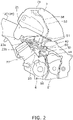
- FIG. 2 is a left side view of the engine 6 and the surroundings thereof.
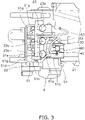
- FIG. 3 is a top view of the engine 6 and the surroundings thereof.
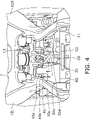
- FIG. 4 is a view of the engine 6 and the surroundings thereof seen from behind the vehicle.
- FIG. 5 is an enlarged view of portion of FIG. 2 .
- the engine 6 includes a crankcase 21, a cylinder 22, and a throttle body 23.
- the cylinder 22 extends forward and upward from a front portion of the crankcase 21.
- the throttle body 23 is connected to the cylinder 22.
- the throttle body 23 is disposed directly below the fuel tank 7.
- the throttle body 23 regulates the amount of air taken into the engine 6.
- An air cleaner 25 is connected to the throttle body 23.
- the air cleaner 25 is disposed directly above the cylinder 22.
- the throttle body 23 includes a plurality of throttles 23a and a plurality of connection ports 23b provided to the plural throttles 23a on a one-to-one basis.
- the plural throttles 23a are disposed away from each other at intervals in the right-and-left direction.
- the plural throttles 23a each have a cylindrical shape and extend rearward and upward from the cylinder 22.
- the plural throttles 23a are each provided with a throttle valve (not shown in the drawings) disposed in the interior thereof. It should be noted that the throttle body 23 may employ a configuration including only one throttle 23a.
- a first hose 51 (to be described) is connected to each connection port 23b.
- Each connection port 23b is disposed on a more front side than each throttle 23a.
- Each connection port 23b extends forward and upward from the outer peripheral portion of each throttle 23a toward the head pipe 11.
- a front end 231b of each connection port 23b is located on a more front side than each throttle 23a.
- the fuel tank 7 is disposed behind the head pipe 11.
- the fuel tank 7 is disposed directly above the engine 6 and the main frame 12.
- the seat 8 is disposed behind the fuel tank 7.
- the seat 8 extends in the back-and-forth direction.
- the straddled vehicle 100 includes a canister 30, a purge valve 40, first to fourth hoses 51 to 54, a starter motor 56, and a holder 60.
- the canister 30 is held by the holder 60.
- the canister 30 is disposed on a more rear side than the throttle body 23, while being disposed directly below the fuel tank 7.
- the canister 30 is disposed behind the throttle body 23.
- the canister 30 overlaps the cylinder 22 in the back-and-forth direction.
- the canister 30 is disposed directly above the crankcase 21. As shown in FIG. 3 , the canister 30 does not overlap the throttle body 23 in the vehicle plan view.
- the canister 30 is disposed inside the vehicle body frame 2.
- the canister 30 is disposed directly below the main frame 12.
- the canister 30 does not overlap the main frame 12 in the vehicle side view.
- the canister 30 is disposed between the left main frame 12L and the right main frame 12R.
- FIG. 6 is a left side view of the canister 30, the purge valve 40, the starter motor 56, and the holder 60.
- FIG. 7 is a top view of the canister 30, the purge valve 40, and the holder 60.
- the canister 30 includes a body 30a, a plurality of ribs 30b, first to third connection ports 30c to 30e, and a plurality of cooling fins 30f.
- the body 30a has an approximately cubic shape and slants with respect to a horizontal direction in the vehicle side view.
- the body 30a slants such that a front portion thereof is located on an upper side than a rear portion thereof.
- the body 30a includes a front surface portion 301a, a rear surface portion 301b, a left surface portion 301c, a right surface portion 301d, an upper surface portion 301e, and a lower surface portion 301f.
- the front and rear surface portions 301a and 301b, the left and right surface portions 301c and 301d, and the upper and lower surface portions 301e and 301f are pairs of outer surface portions of the body 30a and are located in the back-and-forth direction, the right-and-left direction, and the up-and-down direction, respectively.
- the surface portions 301a to 301f are each made in shape of a plane slanting with respect to the horizontal direction in the vehicle side view.
- the front end of the upper surface portion 301e is located on an upper side than the rear end thereof.
- the front end of the lower surface portion 301f is located on an upper side than the rear end thereof.
- the front surface portion 301a extends upward and rearward from the front end of the lower surface portion 301f.
- the rear surface portion 301b extends upward and rearward from the rear end of the lower surface portion 301f.
- the body 30a is greater in dimension in both the right-and-left direction and the back-and-forth direction than in the up-and-down direction.
- the body 30a is greater in dimension in the right-and-left direction than in the back-and-forth direction.
- the left surface portion 301c is shaped to have a greater diameter than the right surface portion 301d.
- the plural ribs 30b are composed of two or more ribs 30b provided on the upper surface portion 301e of the body 30a and two or more ribs 30b provided on the lower surface portion 301f of the body 30a.
- the plural ribs 30b each extend in the back-and-forth direction.
- the first and second connection ports 30c and 30d protrude from the right surface portion 301d of the body 30a in the vehicle width direction.
- the first connection port 30c is a port that the third hose 53 extending from the fuel tank 7 is connected.
- the second connection port 30d is disposed behind the first connection port 30c.
- the second connection port 30d is connected to the purge valve 40 through the second hose 52.
- the third connection port 30e protrudes from the left surface portion 301c of the body 30a in the vehicle width direction.
- the third connection port 30e is a port that the fourth hose 54 is connected for discharging air in the canister 30.
- the plural cooling fins 30f protrude from the left surface portion 301c of the body 30a in the vehicle width direction, while extending in the back-and-forth direction.
- the plural cooling fins 30f downwardly slant from front to rear.
- the plural cooling fins 30f are disposed away from each other at intervals in the up-and-down direction.
- the purge valve 40 is connected to both the canister 30 and the throttle body 23.
- the purge valve 40 is disposed in an intake pathway that connects the canister 30 and the throttle body 23 to each other.
- the purge valve 40 regulates the flow rate of volatilized gasoline to be supplied to the throttle body 23 from the canister 30.
- the purge valve 40 is controlled by an engine control unit (not shown in the drawings).
- the purge valve 40 is held by the holder 60.
- the purge valve 40 is disposed directly above the canister 30.
- the purge valve 40 entirely overlaps the canister 30 in the vehicle plan view.
- the purge valve 40 entirely overlaps the upper surface portion 301e of the body 30a of the canister 30 in the vehicle plan view.
- the purge valve 40 is disposed on a more rear side than the throttle body 23.
- the purge valve 40 overlaps the throttle body 23 in the vehicle back-and-forth direction in the vehicle side view.
- the purge valve 40 is disposed inside the vehicle body frame 2.
- the purge valve 40 overlaps the vehicle body frame 2 in the vehicle side view.
- the purge valve 40 overlaps the main frame 12 in the vehicle side view.
- the purge valve 40 overlaps the cross frame 13 in the vehicle plan view. It should be noted that the purge valve 40 may entirely overlap the main frame 12 in the vehicle side view, or alternatively, may not overlap the main frame 12 in the vehicle side view.
- the purge valve 40 includes a body 40a, a coupling portion 40b, a first connection port 40c, a second connection port 40d, and a third connection port 40e.
- the body 40a is greater in dimension in the right-and-left direction than in both the back-and-forth direction and the up-and-down direction.
- the body 40a is held by the holder 60 while in contact therewith. As shown in FIG. 7 , the body 40a is disposed on a more rear side than the first connection port 30c of the canister 30, while being disposed on a more front side than the second connection port 30d of the canister 30.
- the coupling portion 40b extends from the left end of the body 40a in the vehicle width direction.
- the first and second connection ports 40c and 40d are connected to the body 40a through the coupling portion 40b.
- the first and second connection ports 40c and 40d extend forward and downward from the coupling portion 40b. It should be noted that the coupling portion 40b may be omitted. In other words, the first and second connection ports 40c and 40d may be directly connected to the body 40a.
- the first connection port 40c is connected to the throttle body 23 through the first hose 51.
- the first connection port 40c is disposed on a lower side than the connection ports 23b of the throttle body 23.
- the connection ports 23b of the throttle body 23 are disposed on an upper side than the first connection port 40c.
- the second connection port 40d is connected to the canister 30 through the second hose 52.
- the second connection port 40d is disposed between the body 40a and the first connection port 40c.
- the second connection port 40d is located on an upper side than the second connection port 30d of the canister 30.
- the third connection port 40e is a port to which an electric cable (not shown in the drawings) is plugged for connecting the purge valve 40 and the engine control unit to each other.
- the third connection port 40e extends forward and downward from the right end of the body 40a.
- the first hose 51 is an exemplary hose.
- the first hose 51 connects the throttle body 23 and the purge valve 40 to each other.
- the first hose 51 is connected at one end thereof to the connection ports 23b of the throttle body 23, while being connected at the other end thereof to the first connection port 40c of the purge valve 40.
- the first hose 51 includes a first portion 51a, a second portion 51b, a third portion 51c, and a fourth portion 51d.
- the first portion 51a is connected at the rear end thereof to the first connection port 40c of the purge valve 40 and extends forward and downward toward the throttle body 23.
- the second portion 51b extends forward and upward from the front end of the first portion 51a.
- the front end of the second portion 51b is located outside the rear end thereof in the vehicle width direction.
- the front end of the second portion 51b overlaps the throttles 23a of the throttle body 23 in the vehicle side view.
- the second portion 51b is greater in dimension than the first portion 51a.
- the third portion 51c extends forward and upward from the front end of the second portion 51b.
- the third portion 51c slants more gently than the second portion 51b.
- the front end of the third portion 51c is disposed both on a more front side and an upper side than the connection ports 23b of the throttle body 23.
- the fourth portion 51d is connected to the connection ports 23b that are provided for the throttles 23a on a one-to-one basis.
- the fourth portion 51d includes a first extended portion 51e and a plurality of extended portions 51g.
- the first extended portion 51e extends from the front end of the third portion 51c in the vehicle width direction.
- the plural extended portions 51g are branched from the first extended portion 51e.
- the plural extended portions 51g extend downward and rearward toward the connection ports 23b of the throttle body 23.
- the second hose 52 connects the canister 30 and the purge valve 40 to each other.
- the second hose 52 is connected at one end thereof to the second connection port 30d of the canister 30, while being connected at the other end thereof to the second connection port 40d of the purge valve 40.
- a portion of the second hose 52 overlaps the front surface portion 301a in the vehicle plan view.
- the third hose 53 connects the fuel tank 7 and the canister 30 to each other.
- the third hose 53 is connected at one end thereof to a cap 7a of the fuel tank 7, while being connected at the other end thereof to the first connection port 30c of the canister 30.
- the third hose 53 extends downward from the cap 7a of the fuel tank 7.
- the fourth hose 54 is an exemplary discharge hose.
- the fourth hose 54 discharges the air in the canister 30. As shown in FIGS. 5 and 6 , the fourth hose 54 is connected at one end thereof to the third connection port 30e of the canister 30, while being opened at the other end thereof.
- the fourth hose 54 is connected to the canister 30 in a position located behind the engine 6.
- the fourth hose 54 extends downward from the third connection port 30e.
- the starter motor 56 is held by the holder 60.
- the starter motor 56 is attached to the engine 6.
- the starter motor 56 is attached to a motor mount (not shown in the drawings) provided on the crankcase 21.
- the starter motor 56 is disposed directly below the canister 30.
- the starter motor 56 is disposed on a more front side than the purge valve 40.
- the front end of the starter motor 56 is disposed on a more front side than the front surface portion 301a of the canister 30.
- the rear end of the starter motor 56 is located on a more front side than the rear surface portion 301b of the canister 30.
- the starter motor 56 overlaps the purge valve 40 in the vehicle plan view.
- FIG. 8 is a perspective view of the crankcase 21, the starter motor 56, and the holder 60 seen from the right rear of the vehicle. It should be noted that in FIG. 8 , the canister 30 and the purge valve 40 are omitted.
- the starter motor 56 includes a motor body 56a, a rotational shaft 56b, a first bracket portion 56c, and a second bracket portion 56d.
- the motor body 56a has an approximately cylindrical shape.
- the rotational shaft 56b extends in the vehicle width direction.
- the first and second bracket portions 56c and 56d protrude from the right end of the motor body 56a in the vehicle width direction.
- the first and second bracket portions 56c and 56d include holes, respectively, into which fixation members such as bolts are inserted.
- the first and second bracket portions 56c and 56d are fixed to the crankcase 21 by the fixation members inserted into the holes.
- the first and second bracket portions 56c and 56d are disposed at an interval in the back-and-forth direction.
- FIG. 9 is a perspective view of the holder 60.
- the holder 60 is made of elastic material such as rubber.
- the holder 60 collectively holds the canister 30, the purge valve 40, and the starter motor 56.
- the holder 60 includes a canister holding portion 61, a valve holding portion 62, and a motor holding portion 63.
- the canister holding portion 61, the valve holding portion 62, and the motor holding portion 63 are each made in shape of a hole penetrating the holder 60 in the vehicle width direction.
- the canister holding portion 61, the valve holding portion 62, and the motor holding portion 63 are formed independently in the holder 60.
- the canister holding portion 61 is disposed between the valve holding portion 62 and the motor holding portion 63.
- the canister holding portion 61 is shaped to fit the contour of the body 30a of the canister 30. Therefore, the canister holding portion 61 is made in shape of an approximately rectangular hole in the vehicle side view.
- the canister 30 is inserted into the canister holding portion 61 along the vehicle width direction and is held by the canister holding portion 61.
- the canister holding portion 61 includes a fitting portion 61a, to which the upper surface portion 301e of the canister 30 is fitted, and a plurality of slits 61b, to which the plural ribs 30b of the canister 30 are locked.
- An inner surface 61c of the fitting portion 61a is shaped to fit the upper surface portion 301e of the canister 30 so as to be in contact therewith.
- the fitting portion 61a slants with respect to the horizontal direction in the vehicle side view.
- the fitting portion 61a slants such that a front portion thereof is located on an upper side than a rear portion thereof.
- the plural slits 61b are composed of two or more slits 61b provided in a lower portion of the canister holding portion 61 and two or more slits 61b provided in the fitting portion 61a.
- the valve holding portion 62 is disposed on the upper side of the canister holding portion 61.
- the valve holding portion 62 is shaped to protrude upward from the fitting portion 61a of the canister holding portion 61.
- the valve holding portion 62 is eccentric to the second connection port 30d on the fitting portion 61a.
- the valve holding portion 62 entirely overlaps the canister holding portion 61 in the vehicle plan view.
- the valve holding portion 62 overlaps the motor holding portion 63 in the vehicle plan view.
- the purge valve 40 is inserted into the valve holding portion 62 along the vehicle width direction and is held by the valve holding portion 62.
- the valve holding portion 62 is shaped to fit the contour of the body 40a of the purge valve 40, whereby the body 40a of the purge valve 40 is held by the valve holding portion 62 while in contact therewith.
- the motor holding portion 63 is disposed on the lower side of the canister holding portion 61.
- the starter motor 56 is inserted into the motor holding portion 63 along the vehicle width direction and is held by the motor holding portion 63.
- the motor holding portion 63 is shaped to fit the contour of the motor body 56a of the starter motor 56. Therefore, the motor holding portion 63 has an approximately cylindrical shape in the vehicle side view.
- the motor body 56a of the starter motor 56 is held by the motor holding portion 63 while in contact therewith.
- the holder 60 includes a plurality of support protrusions 64a to 64c, a protruding portion 65, and a guide portion 66.
- the support protrusion 64a protrudes from a front lower portion of the motor holding portion 63.
- the support protrusions 64b and 64c protrude from a rear lower portion of the motor holding portion 63.
- the support protrusions 64b and 64c are separated in the vehicle width direction. As shown in FIG. 8 , the support protrusion 64a makes contact with the cylinder 22, whereas the support protrusions 64b and 64c make contact with the crankcase 21.
- the protruding portion 65 protrudes from a lower portion of the motor holding portion 63 in the vehicle width direction. As shown in FIG. 8 , the protruding portion 65 is sandwiched between the first bracket portion 56c and the second bracket portion 56d of the starter motor 56.
- the guide portion 66 guides a hose 58 connected to the fuel tank 7.
- the hose 58 is connected at one end thereof to the fuel tank 7, while being opened at the other end thereof.
- the hose 58 extends approximately downward from the fuel tank 7.
- the other end of the hose 58 is disposed behind the engine 6.
- the guide portion 66 is made in shape of a clamp and clamps the hose 58. A portion of the hose 58 guided by the guide portion 66 overlaps the fourth hose 54 in the vehicle side view.
- the canister 30 is disposed on a more rear side than the throttle body 23, whereas the purge valve 40 is disposed directly above the canister 30, while overlapping the throttle body 23 in the vehicle back-and-forth direction in the vehicle side view. Because of this, the purge valve 40 is enabled to be disposed in a position adjacent to the throttle body 23, whereby it is possible to shorten the first hose 51 that connects the throttle body 23 and the purge valve 40 to each other. Consequently, an efficient layout is enabled for the first hose 51. Besides, the canister 30 is disposed directly below the fuel tank 7, whereby it is possible to shorten the third hose 53 connecting the canister 30 and the fuel tank 7 to each other.
- the canister 30 and the purge valve 40 are disposed inside the vehicle body frame 2. Hence, an impact can be prevented from directly acting on the canister 30, for instance, when the vehicle falls over.
- the purge valve 40 overlaps the vehicle body frame 2 in the vehicle side view. Hence, an impact can be prevented from directly acting on the canister 30, for instance, when the vehicle falls over, and simultaneously, external aesthetics can be enhanced.
- the canister 30 does not overlap the throttle body 23 in the vehicle plan view. Hence, an efficient layout is enabled for the first to fourth hoses 51 to 54 disposed in the surroundings of the canister 30.
- the holder 60 collectively holds the canister 30, the purge valve 40, and the starter motor 56. Hence, the purge valve 40 can be disposed near the canister 30. Accordingly, it is possible to shorten the second hose 52 connecting the purge valve 40 and the canister 30 to each other. Besides, increase in number of components can be inhibited.
- the first hose 51 connecting the throttle body 23 and the purge valve 40 to each other, includes the first portion 51a and the second portion 51b.
- the first portion 51a is connected to the first connection port 40c of the purge valve 40 and extends forward and downward toward the throttle body 23.
- the second portion 51b extends forward and upward from the first portion 51a. Accordingly, gasoline can be inhibited from accumulating in and sticking to the first connection port 40c.
- connection ports 23b of the throttle body 23 are disposed on an upper side than the first connection port 40c of the purge valve 40. Hence, volatilized gasoline is likely to be led to the throttle body 23.
- connection ports 23b of the throttle body 23 are disposed on a more front side than the throttles 23a, while extending forward and upward toward the head pipe 11. Hence, volatilized gasoline is likely to be led to the throttle body 23.
- the fourth hose 54 is connected to the canister 30 in the position behind the engine 6. Hence, rainwater, flying toward the vehicle from ahead during traveling, is unlikely to hit the fourth hose 54.
- the straddled vehicle 100 is not limited to a scooter type vehicle, and alternatively, may be another type of vehicle.
- the vehicle body frame 2 and the engine 6 may be changed in structure.
- the body 30a of the canister 30 has an approximately cubic shape.
- the body 30a may have a cylindrical shape.
Abstract
Description
- The present invention relates to a straddled vehicle.
- A straddled vehicle disclosed in
Japan Laid-open Patent Application Publication No. 2012-1119 - In such a well-known straddled vehicle, the purge valve is disposed in alignment with the canister in the vehicle width direction. This results in increase in length of the hose that connects the purge valve and the throttle body to each other, whereby an efficient layout is made difficult for the hose.
- It is an object of the present invention to provide a straddled vehicle that enables an efficient layout for a hose connecting a purge valve and a throttle body to each other.
- A straddled vehicle according to an aspect of the present invention includes a vehicle body frame, an engine, a fuel tank, a canister, a purge valve, and a hose. The vehicle body frame includes a head pipe. The engine includes a throttle body. The engine is supported by the vehicle body frame. The fuel tank is disposed behind the head pipe. The canister is disposed on a more rear side than the throttle body, while being disposed directly below the fuel tank. The purge valve is disposed directly above the canister, overlaps the throttle body in a vehicle back-and-forth direction in a vehicle side view, and is connected to the canister and the throttle body. The hose connects the throttle body and the purge valve to each other.
- In the straddled vehicle according to the present aspect, the canister is disposed on a more rear side than the throttle body, whereas the purge valve is disposed directly above the canister, while overlapping the throttle body in the vehicle back-and-forth direction in the vehicle side view. Because of this, the purge valve is enabled to be disposed in a position adjacent to the throttle body, whereby it is possible to shorten the hose connecting the throttle body and the purge valve to each other. Accordingly, an efficient layout is enabled for the hose connecting the throttle body and the purge valve to each other. Besides, the canister is disposed directly below the fuel tank, whereby it is possible to shorten another hose connecting the canister and the fuel tank to each other.
- The canister and the purge valve may be disposed inside the vehicle body frame. In this case, an impact can be prevented from directly acting on the canister, for instance, when the vehicle falls over.
- The purge valve may overlap the vehicle body frame in the vehicle side view. In this case, an impact can be prevented from directly acting on the canister, for instance, when the vehicle falls over, and simultaneously, external aesthetics can be enhanced.
- The canister may not overlap the throttle body in a vehicle plan view. In this case, an efficient layout is enabled for hoses disposed in the surroundings of the canister.
- The straddled vehicle may further include a starter motor and a holder. The starter motor may be attached to the engine. The holder may collectively hold the canister, the purge valve, and the starter motor. In this case, it is possible to shorten yet another hose connecting the purge valve and the canister to each other. Besides, increase in number of components can be inhibited.
- The purge valve may include a connection port, to which the hose is connected, and that extends forward and downward toward the head pipe. The hose may include a first portion and a second portion. The first portion may be connected to the connection port of the purge valve and may extend forward and downward toward the throttle body. The second portion may extend forward and upward from the first portion. In this case, gasoline can be inhibited from accumulating in and sticking to the connection port.
- The throttle body may include a connection port to which the hose is connected. The connection port of the throttle body may be disposed on an upper side than the connection port of the purge valve. In this case, it becomes likely that volatilized gasoline is led to the throttle body.
- The throttle body may further include a throttle. The connection port of the throttle body may be disposed on a more front side than the throttle and may extend forward and upward toward the head pipe. In this case, it becomes likely that volatilized gasoline is led to the throttle body.
- The straddled vehicle may further include a discharge hose for discharging air inside the canister. The discharge hose may be connected to the canister in a position located behind the engine. In this case, rainwater, flying toward the vehicle from ahead during traveling, is unlikely to hit the discharge hose.
-
-
FIG. 1 is a left side view of a straddled vehicle. -
FIG. 2 is a left side view of an engine and the surroundings thereof. -
FIG. 3 is a top view of the engine and the surroundings thereof. -
FIG. 4 is a view of the engine and the surroundings thereof seen from behind the straddled vehicle. -
FIG. 5 is an enlarged view of portion ofFIG. 2 . -
FIG. 6 is a left side view of a canister, a purge valve, a starter motor, and a holder. -
FIG. 7 is a top view of the canister, the purge valve, and the holder. -
FIG. 8 is a perspective view of a crankcase, the starter motor, and the holder seen from the right rear of the straddled vehicle. -
FIG. 9 is a perspective view of the holder. - A preferred embodiment of a straddled vehicle according to an aspect of the present invention will be hereinafter explained with reference to drawings. It should be noted that in the following explanation, terms indicating such directions as "back and forth", "up and down" and "right and left" are explained based on directions seen from a rider in operation of a straddled
vehicle 100. -
FIG. 1 is a left side view of the straddledvehicle 100. The straddledvehicle 100 includes avehicle body frame 2, asteering device 3, afront wheel 4, a rear wheel 5, anengine 6, afuel tank 7, and a seat 8. - The
vehicle body frame 2 includes ahead pipe 11, amain frame 12, and a cross frame 13 (seeFIG. 4 ). Thehead pipe 11 extends forward and downward. Thehead pipe 11 is disposed in the center of the straddledvehicle 100 in a vehicle width direction. - The
main frame 12 is connected at the front end thereof to thehead pipe 11. Themain frame 12 is composed of components provided right and left. Themain frame 12 extends rearward from thehead pipe 11, while branching therefrom right and left into the components. It should be noted that the term "connection" is not limited to direct connection and encompasses indirect connection. Besides, the term "connection" is not limited to a condition that separate members are fixed to each other and encompasses a condition that a plurality of portions in an integrated member continue to each other. - The
main frame 12 includes a leftmain frame 12L and a rightmain frame 12R (seeFIG. 2 ). The leftmain frame 12L is disposed on the left side of the center of the straddledvehicle 100 in the vehicle width direction. The rightmain frame 12R is disposed on the right side of the center of the straddledvehicle 100 in the vehicle width direction. Thecross frame 13 extends in the vehicle width direction and connects the leftmain frame 12L and the rightmain frame 12R to each other. Thecross frame 13 overlaps theengine 6 in a vehicle plan view. - The
steering device 3 is supported by thehead pipe 11 so as to be turnable. Thesteering device 3 includes afront fork 14 and ahandle portion 15. Thefront fork 14 extends forward and downward. Thefront fork 14 is connected at the lower end thereof to thefront wheel 4. Thehandle portion 15 is connected to thefront fork 14. Thehandle portion 15 includes ahandlebar 15a extending in the right-and-left direction. Thehandlebar 15a is provided with grips on both ends thereof. - The
front wheel 4 is supported by thefront fork 14 so as to be rotatable. The rear wheel 5 is supported by aswing arm 16 disposed behind theengine 6 so as to be rotatable. - The
engine 6 is supported by thevehicle body frame 2. Theengine 6 is disposed directly below themain frame 12. -
FIG. 2 is a left side view of theengine 6 and the surroundings thereof.FIG. 3 is a top view of theengine 6 and the surroundings thereof.FIG. 4 is a view of theengine 6 and the surroundings thereof seen from behind the vehicle.FIG. 5 is an enlarged view of portion ofFIG. 2 . Theengine 6 includes acrankcase 21, acylinder 22, and athrottle body 23. - The
cylinder 22 extends forward and upward from a front portion of thecrankcase 21. Thethrottle body 23 is connected to thecylinder 22. Thethrottle body 23 is disposed directly below thefuel tank 7. Thethrottle body 23 regulates the amount of air taken into theengine 6. Anair cleaner 25 is connected to thethrottle body 23. Theair cleaner 25 is disposed directly above thecylinder 22. - The
throttle body 23 includes a plurality ofthrottles 23a and a plurality ofconnection ports 23b provided to the plural throttles 23a on a one-to-one basis. The plural throttles 23a are disposed away from each other at intervals in the right-and-left direction. The plural throttles 23a each have a cylindrical shape and extend rearward and upward from thecylinder 22. The plural throttles 23a are each provided with a throttle valve (not shown in the drawings) disposed in the interior thereof. It should be noted that thethrottle body 23 may employ a configuration including only onethrottle 23a. A first hose 51 (to be described) is connected to eachconnection port 23b. Eachconnection port 23b is disposed on a more front side than eachthrottle 23a. Eachconnection port 23b extends forward and upward from the outer peripheral portion of eachthrottle 23a toward thehead pipe 11. As shown inFIG. 5 , afront end 231b of eachconnection port 23b is located on a more front side than eachthrottle 23a. - The
fuel tank 7 is disposed behind thehead pipe 11. Thefuel tank 7 is disposed directly above theengine 6 and themain frame 12. The seat 8 is disposed behind thefuel tank 7. The seat 8 extends in the back-and-forth direction. - As shown in
FIGS. 2 to 5 , the straddledvehicle 100 includes acanister 30, apurge valve 40, first tofourth hoses 51 to 54, astarter motor 56, and aholder 60. - The
canister 30 is held by theholder 60. Thecanister 30 is disposed on a more rear side than thethrottle body 23, while being disposed directly below thefuel tank 7. In the present preferred embodiment, thecanister 30 is disposed behind thethrottle body 23. In the vehicle side view, thecanister 30 overlaps thecylinder 22 in the back-and-forth direction. Thecanister 30 is disposed directly above thecrankcase 21. As shown inFIG. 3 , thecanister 30 does not overlap thethrottle body 23 in the vehicle plan view. - As shown in
FIGS. 2 and4 , thecanister 30 is disposed inside thevehicle body frame 2. Thecanister 30 is disposed directly below themain frame 12. Thecanister 30 does not overlap themain frame 12 in the vehicle side view. As seen from behind the vehicle, thecanister 30 is disposed between the leftmain frame 12L and the rightmain frame 12R. -
FIG. 6 is a left side view of thecanister 30, thepurge valve 40, thestarter motor 56, and theholder 60.FIG. 7 is a top view of thecanister 30, thepurge valve 40, and theholder 60. Thecanister 30 includes abody 30a, a plurality ofribs 30b, first tothird connection ports 30c to 30e, and a plurality ofcooling fins 30f. - The
body 30a has an approximately cubic shape and slants with respect to a horizontal direction in the vehicle side view. Thebody 30a slants such that a front portion thereof is located on an upper side than a rear portion thereof. When described in detail, thebody 30a includes afront surface portion 301a, arear surface portion 301b, aleft surface portion 301c, aright surface portion 301d, anupper surface portion 301e, and alower surface portion 301f. The front andrear surface portions right surface portions lower surface portions body 30a and are located in the back-and-forth direction, the right-and-left direction, and the up-and-down direction, respectively. Thesurface portions 301a to 301f are each made in shape of a plane slanting with respect to the horizontal direction in the vehicle side view. - The front end of the
upper surface portion 301e is located on an upper side than the rear end thereof. The front end of thelower surface portion 301f is located on an upper side than the rear end thereof. Thefront surface portion 301a extends upward and rearward from the front end of thelower surface portion 301f. Therear surface portion 301b extends upward and rearward from the rear end of thelower surface portion 301f. Thebody 30a is greater in dimension in both the right-and-left direction and the back-and-forth direction than in the up-and-down direction. Thebody 30a is greater in dimension in the right-and-left direction than in the back-and-forth direction. Theleft surface portion 301c is shaped to have a greater diameter than theright surface portion 301d. Theplural ribs 30b are composed of two ormore ribs 30b provided on theupper surface portion 301e of thebody 30a and two ormore ribs 30b provided on thelower surface portion 301f of thebody 30a. Theplural ribs 30b each extend in the back-and-forth direction. - As shown in
FIG. 7 , the first andsecond connection ports right surface portion 301d of thebody 30a in the vehicle width direction. Thefirst connection port 30c is a port that thethird hose 53 extending from thefuel tank 7 is connected. Thesecond connection port 30d is disposed behind thefirst connection port 30c. Thesecond connection port 30d is connected to thepurge valve 40 through thesecond hose 52. Thethird connection port 30e protrudes from theleft surface portion 301c of thebody 30a in the vehicle width direction. Thethird connection port 30e is a port that thefourth hose 54 is connected for discharging air in thecanister 30. - The
plural cooling fins 30f protrude from theleft surface portion 301c of thebody 30a in the vehicle width direction, while extending in the back-and-forth direction. Theplural cooling fins 30f downwardly slant from front to rear. Theplural cooling fins 30f are disposed away from each other at intervals in the up-and-down direction. - The
purge valve 40 is connected to both thecanister 30 and thethrottle body 23. Thepurge valve 40 is disposed in an intake pathway that connects thecanister 30 and thethrottle body 23 to each other. Thepurge valve 40 regulates the flow rate of volatilized gasoline to be supplied to thethrottle body 23 from thecanister 30. Thepurge valve 40 is controlled by an engine control unit (not shown in the drawings). - The
purge valve 40 is held by theholder 60. Thepurge valve 40 is disposed directly above thecanister 30. Thepurge valve 40 entirely overlaps thecanister 30 in the vehicle plan view. In more detail, thepurge valve 40 entirely overlaps theupper surface portion 301e of thebody 30a of thecanister 30 in the vehicle plan view. As shown inFIG. 5 , thepurge valve 40 is disposed on a more rear side than thethrottle body 23. Thepurge valve 40 overlaps thethrottle body 23 in the vehicle back-and-forth direction in the vehicle side view. Thepurge valve 40 is disposed inside thevehicle body frame 2. Thepurge valve 40 overlaps thevehicle body frame 2 in the vehicle side view. When described in detail, a portion of thepurge valve 40 overlaps themain frame 12 in the vehicle side view. Thepurge valve 40 overlaps thecross frame 13 in the vehicle plan view. It should be noted that thepurge valve 40 may entirely overlap themain frame 12 in the vehicle side view, or alternatively, may not overlap themain frame 12 in the vehicle side view. - The
purge valve 40 includes abody 40a, acoupling portion 40b, afirst connection port 40c, asecond connection port 40d, and athird connection port 40e. Thebody 40a is greater in dimension in the right-and-left direction than in both the back-and-forth direction and the up-and-down direction. Thebody 40a is held by theholder 60 while in contact therewith. As shown inFIG. 7 , thebody 40a is disposed on a more rear side than thefirst connection port 30c of thecanister 30, while being disposed on a more front side than thesecond connection port 30d of thecanister 30. Thecoupling portion 40b extends from the left end of thebody 40a in the vehicle width direction. The first andsecond connection ports body 40a through thecoupling portion 40b. The first andsecond connection ports coupling portion 40b. It should be noted that thecoupling portion 40b may be omitted. In other words, the first andsecond connection ports body 40a. - As shown in
FIG. 5 , thefirst connection port 40c is connected to thethrottle body 23 through thefirst hose 51. Thefirst connection port 40c is disposed on a lower side than theconnection ports 23b of thethrottle body 23. In other words, theconnection ports 23b of thethrottle body 23 are disposed on an upper side than thefirst connection port 40c. As shown inFIG. 7 , thesecond connection port 40d is connected to thecanister 30 through thesecond hose 52. Thesecond connection port 40d is disposed between thebody 40a and thefirst connection port 40c. Thesecond connection port 40d is located on an upper side than thesecond connection port 30d of thecanister 30. Thethird connection port 40e is a port to which an electric cable (not shown in the drawings) is plugged for connecting thepurge valve 40 and the engine control unit to each other. Thethird connection port 40e extends forward and downward from the right end of thebody 40a. - Next, the
first hose 51 will be explained in detail with reference toFIGS. 3 and5 . Thefirst hose 51 is an exemplary hose. Thefirst hose 51 connects thethrottle body 23 and thepurge valve 40 to each other. Thefirst hose 51 is connected at one end thereof to theconnection ports 23b of thethrottle body 23, while being connected at the other end thereof to thefirst connection port 40c of thepurge valve 40. Thefirst hose 51 includes afirst portion 51a, asecond portion 51b, athird portion 51c, and afourth portion 51d. - The
first portion 51a is connected at the rear end thereof to thefirst connection port 40c of thepurge valve 40 and extends forward and downward toward thethrottle body 23. Thesecond portion 51b extends forward and upward from the front end of thefirst portion 51a. The front end of thesecond portion 51b is located outside the rear end thereof in the vehicle width direction. The front end of thesecond portion 51b overlaps thethrottles 23a of thethrottle body 23 in the vehicle side view. Thesecond portion 51b is greater in dimension than thefirst portion 51a. - The
third portion 51c extends forward and upward from the front end of thesecond portion 51b. Thethird portion 51c slants more gently than thesecond portion 51b. The front end of thethird portion 51c is disposed both on a more front side and an upper side than theconnection ports 23b of thethrottle body 23. Thefourth portion 51d is connected to theconnection ports 23b that are provided for thethrottles 23a on a one-to-one basis. As shown inFIG. 3 , thefourth portion 51d includes a firstextended portion 51e and a plurality ofextended portions 51g. The firstextended portion 51e extends from the front end of thethird portion 51c in the vehicle width direction. The pluralextended portions 51g are branched from the firstextended portion 51e. The pluralextended portions 51g extend downward and rearward toward theconnection ports 23b of thethrottle body 23. - As shown in
FIG. 7 , thesecond hose 52 connects thecanister 30 and thepurge valve 40 to each other. Thesecond hose 52 is connected at one end thereof to thesecond connection port 30d of thecanister 30, while being connected at the other end thereof to thesecond connection port 40d of thepurge valve 40. A portion of thesecond hose 52 overlaps thefront surface portion 301a in the vehicle plan view. - As shown in
FIGS. 2 and4 , thethird hose 53 connects thefuel tank 7 and thecanister 30 to each other. Thethird hose 53 is connected at one end thereof to acap 7a of thefuel tank 7, while being connected at the other end thereof to thefirst connection port 30c of thecanister 30. The gasoline, volatilized inside thefuel tank 7, flows through thethird hose 53 to thecanister 30 and is absorbed therein. Thethird hose 53 extends downward from thecap 7a of thefuel tank 7. - The
fourth hose 54 is an exemplary discharge hose. Thefourth hose 54 discharges the air in thecanister 30. As shown inFIGS. 5 and6 , thefourth hose 54 is connected at one end thereof to thethird connection port 30e of thecanister 30, while being opened at the other end thereof. Thefourth hose 54 is connected to thecanister 30 in a position located behind theengine 6. Thefourth hose 54 extends downward from thethird connection port 30e. - As shown in
FIG. 6 , thestarter motor 56 is held by theholder 60. Thestarter motor 56 is attached to theengine 6. When described in detail, thestarter motor 56 is attached to a motor mount (not shown in the drawings) provided on thecrankcase 21. Thestarter motor 56 is disposed directly below thecanister 30. Thestarter motor 56 is disposed on a more front side than thepurge valve 40. The front end of thestarter motor 56 is disposed on a more front side than thefront surface portion 301a of thecanister 30. The rear end of thestarter motor 56 is located on a more front side than therear surface portion 301b of thecanister 30. Thestarter motor 56 overlaps thepurge valve 40 in the vehicle plan view. -
FIG. 8 is a perspective view of thecrankcase 21, thestarter motor 56, and theholder 60 seen from the right rear of the vehicle. It should be noted that inFIG. 8 , thecanister 30 and thepurge valve 40 are omitted. As shown inFIGS. 6 and8 , thestarter motor 56 includes amotor body 56a, arotational shaft 56b, afirst bracket portion 56c, and asecond bracket portion 56d. Themotor body 56a has an approximately cylindrical shape. Therotational shaft 56b extends in the vehicle width direction. The first andsecond bracket portions motor body 56a in the vehicle width direction. The first andsecond bracket portions second bracket portions crankcase 21 by the fixation members inserted into the holes. The first andsecond bracket portions -
FIG. 9 is a perspective view of theholder 60. Theholder 60 is made of elastic material such as rubber. Theholder 60 collectively holds thecanister 30, thepurge valve 40, and thestarter motor 56. Theholder 60 includes acanister holding portion 61, avalve holding portion 62, and amotor holding portion 63. Thecanister holding portion 61, thevalve holding portion 62, and themotor holding portion 63 are each made in shape of a hole penetrating theholder 60 in the vehicle width direction. Thecanister holding portion 61, thevalve holding portion 62, and themotor holding portion 63 are formed independently in theholder 60. - The
canister holding portion 61 is disposed between thevalve holding portion 62 and themotor holding portion 63. Thecanister holding portion 61 is shaped to fit the contour of thebody 30a of thecanister 30. Therefore, thecanister holding portion 61 is made in shape of an approximately rectangular hole in the vehicle side view. Thecanister 30 is inserted into thecanister holding portion 61 along the vehicle width direction and is held by thecanister holding portion 61. Thecanister holding portion 61 includes afitting portion 61a, to which theupper surface portion 301e of thecanister 30 is fitted, and a plurality ofslits 61b, to which theplural ribs 30b of thecanister 30 are locked. Aninner surface 61c of thefitting portion 61a is shaped to fit theupper surface portion 301e of thecanister 30 so as to be in contact therewith. Thefitting portion 61a slants with respect to the horizontal direction in the vehicle side view. Thefitting portion 61a slants such that a front portion thereof is located on an upper side than a rear portion thereof. The plural slits 61b are composed of two ormore slits 61b provided in a lower portion of thecanister holding portion 61 and two ormore slits 61b provided in thefitting portion 61a. - The
valve holding portion 62 is disposed on the upper side of thecanister holding portion 61. Thevalve holding portion 62 is shaped to protrude upward from thefitting portion 61a of thecanister holding portion 61. Thevalve holding portion 62 is eccentric to thesecond connection port 30d on thefitting portion 61a. As shown inFIG. 7 , thevalve holding portion 62 entirely overlaps thecanister holding portion 61 in the vehicle plan view. Thevalve holding portion 62 overlaps themotor holding portion 63 in the vehicle plan view. Thepurge valve 40 is inserted into thevalve holding portion 62 along the vehicle width direction and is held by thevalve holding portion 62. In the present preferred embodiment, thevalve holding portion 62 is shaped to fit the contour of thebody 40a of thepurge valve 40, whereby thebody 40a of thepurge valve 40 is held by thevalve holding portion 62 while in contact therewith. - The
motor holding portion 63 is disposed on the lower side of thecanister holding portion 61. Thestarter motor 56 is inserted into themotor holding portion 63 along the vehicle width direction and is held by themotor holding portion 63. In the present preferred embodiment, themotor holding portion 63 is shaped to fit the contour of themotor body 56a of thestarter motor 56. Therefore, themotor holding portion 63 has an approximately cylindrical shape in the vehicle side view. Themotor body 56a of thestarter motor 56 is held by themotor holding portion 63 while in contact therewith. - The
holder 60 includes a plurality ofsupport protrusions 64a to 64c, a protrudingportion 65, and aguide portion 66. Thesupport protrusion 64a protrudes from a front lower portion of themotor holding portion 63. The support protrusions 64b and 64c protrude from a rear lower portion of themotor holding portion 63. The support protrusions 64b and 64c are separated in the vehicle width direction. As shown inFIG. 8 , thesupport protrusion 64a makes contact with thecylinder 22, whereas thesupport protrusions crankcase 21. - As shown in
FIG. 7 , the protrudingportion 65 protrudes from a lower portion of themotor holding portion 63 in the vehicle width direction. As shown inFIG. 8 , the protrudingportion 65 is sandwiched between thefirst bracket portion 56c and thesecond bracket portion 56d of thestarter motor 56. - The
guide portion 66 guides ahose 58 connected to thefuel tank 7. Thehose 58 is connected at one end thereof to thefuel tank 7, while being opened at the other end thereof. Thehose 58 extends approximately downward from thefuel tank 7. The other end of thehose 58 is disposed behind theengine 6. Theguide portion 66 is made in shape of a clamp and clamps thehose 58. A portion of thehose 58 guided by theguide portion 66 overlaps thefourth hose 54 in the vehicle side view. - In the straddled
vehicle 100 according to the present aspect, thecanister 30 is disposed on a more rear side than thethrottle body 23, whereas thepurge valve 40 is disposed directly above thecanister 30, while overlapping thethrottle body 23 in the vehicle back-and-forth direction in the vehicle side view. Because of this, thepurge valve 40 is enabled to be disposed in a position adjacent to thethrottle body 23, whereby it is possible to shorten thefirst hose 51 that connects thethrottle body 23 and thepurge valve 40 to each other. Consequently, an efficient layout is enabled for thefirst hose 51. Besides, thecanister 30 is disposed directly below thefuel tank 7, whereby it is possible to shorten thethird hose 53 connecting thecanister 30 and thefuel tank 7 to each other. - The
canister 30 and thepurge valve 40 are disposed inside thevehicle body frame 2. Hence, an impact can be prevented from directly acting on thecanister 30, for instance, when the vehicle falls over. - The
purge valve 40 overlaps thevehicle body frame 2 in the vehicle side view. Hence, an impact can be prevented from directly acting on thecanister 30, for instance, when the vehicle falls over, and simultaneously, external aesthetics can be enhanced. - The
canister 30 does not overlap thethrottle body 23 in the vehicle plan view. Hence, an efficient layout is enabled for the first tofourth hoses 51 to 54 disposed in the surroundings of thecanister 30. - The
holder 60 collectively holds thecanister 30, thepurge valve 40, and thestarter motor 56. Hence, thepurge valve 40 can be disposed near thecanister 30. Accordingly, it is possible to shorten thesecond hose 52 connecting thepurge valve 40 and thecanister 30 to each other. Besides, increase in number of components can be inhibited. - The
first hose 51, connecting thethrottle body 23 and thepurge valve 40 to each other, includes thefirst portion 51a and thesecond portion 51b. Thefirst portion 51a is connected to thefirst connection port 40c of thepurge valve 40 and extends forward and downward toward thethrottle body 23. Thesecond portion 51b extends forward and upward from thefirst portion 51a. Accordingly, gasoline can be inhibited from accumulating in and sticking to thefirst connection port 40c. - The
connection ports 23b of thethrottle body 23 are disposed on an upper side than thefirst connection port 40c of thepurge valve 40. Hence, volatilized gasoline is likely to be led to thethrottle body 23. - The
connection ports 23b of thethrottle body 23 are disposed on a more front side than thethrottles 23a, while extending forward and upward toward thehead pipe 11. Hence, volatilized gasoline is likely to be led to thethrottle body 23. - The
fourth hose 54 is connected to thecanister 30 in the position behind theengine 6. Hence, rainwater, flying toward the vehicle from ahead during traveling, is unlikely to hit thefourth hose 54. - One preferred embodiment of the present invention has been explained above. However, the present invention is not limited to the preferred embodiment described above, and a variety of changes can be made without departing from the gist of the present invention.
- The straddled
vehicle 100 is not limited to a scooter type vehicle, and alternatively, may be another type of vehicle. Thevehicle body frame 2 and theengine 6 may be changed in structure. - In the preferred embodiment described above, the
body 30a of thecanister 30 has an approximately cubic shape. However, thebody 30a may have a cylindrical shape.
Claims (9)
- A straddled vehicle (100) comprising:a vehicle body frame (2) including a head pipe (11);an engine (6) including a throttle body (23), the engine (6) being supported by the vehicle body frame (2);a fuel tank (7) disposed behind the head pipe (11);a canister (30) disposed on a more rear side than the throttle body (23), the canister (30) disposed directly below the fuel tank (7);a purge valve (40) disposed directly above the canister (30), the purge valve (40) overlapping the throttle body (23) in a vehicle back-and-forth direction in a vehicle side view, the purge valve (40) being connected to the canister (30) and the throttle body (23); anda hose (51) connecting the throttle body (23) and the purge valve (40) to each other.
- The straddled vehicle according to claim 1, wherein the canister (30) and the purge valve (40) are disposed inside the vehicle body frame (2).
- The straddled vehicle according to claim 1 or 2, wherein the purge valve (40) overlaps the vehicle body frame (2) in the vehicle side view.
- The straddled vehicle according to any one of claims 1 to 3, wherein the canister (30) does not overlap the throttle body (23) in a vehicle plan view.
- The straddled vehicle according to any one of claims 1 to 4, further comprising:a starter motor (56) attached to the engine (6); anda holder (60) collectively holding the canister (30), the purge valve (40), and the starter motor (56).
- The straddled vehicle according to any one of claims 1 to 5, whereinthe purge valve (40) includes a connection port (40c) to which the hose (51) is connected, the connection port (40c) extending forward and downward toward the head pipe (11), andthe hose (51) includes a first portion (51a) and a second portion (51b), the first portion (51) being connected to the connection port (40c) of the purge valve (40), the first portion (51a) extending forward and downward toward the throttle body (23), the second portion (51b) extending forward and upward from the first portion (51a).
- The straddled vehicle according to claim 6, whereinthe throttle body (23) includes a connection port (23b) to which the hose (51) is connected, andthe connection port (23b) of the throttle body (23) is disposed on an upper side than the connection port (40c) of the purge valve (40).
- The straddled vehicle according to claim 6 or 7, whereinthe throttle body (23) includes a throttle (23a) and a connection port (23b) to which the hose (51) is connected, andthe connection port (23b) of the throttle body (23) is disposed on a more front side than the throttle (23a), the connection port (23b) of the throttle body (23) extending forward and upward toward the head pipe (11).
- The straddled vehicle according to any one of claims 1 to 8, further comprising:
a discharge hose (54) for discharging air inside the canister (30), the discharge hose (54) being connected to the canister (30) in a position located behind the engine (6).
Applications Claiming Priority (1)
| Application Number | Priority Date | Filing Date | Title |
|---|---|---|---|
| JP2020161187A JP2022054151A (en) | 2020-09-25 | 2020-09-25 | Saddle-riding type vehicle |
Publications (2)
| Publication Number | Publication Date |
|---|---|
| EP3974642A1 true EP3974642A1 (en) | 2022-03-30 |
| EP3974642B1 EP3974642B1 (en) | 2024-03-13 |
Family
ID=77910522
Family Applications (1)
| Application Number | Title | Priority Date | Filing Date |
|---|---|---|---|
| EP21193222.3A Active EP3974642B1 (en) | 2020-09-25 | 2021-08-26 | Straddled vehicle |
Country Status (2)
| Country | Link |
|---|---|
| EP (1) | EP3974642B1 (en) |
| JP (1) | JP2022054151A (en) |
Citations (4)
| Publication number | Priority date | Publication date | Assignee | Title |
|---|---|---|---|---|
| JP2012001119A (en) | 2010-06-17 | 2012-01-05 | Suzuki Motor Corp | Canister arrangement structure of motorcycle |
| EP2860089A1 (en) * | 2013-10-10 | 2015-04-15 | Yamaha Hatsudoki Kabushiki Kaisha | Saddle-ride type vehicle |
| DE102017219422A1 (en) * | 2016-11-14 | 2018-05-17 | Suzuki Motor Corporation | ARRANGEMENT STRUCTURE FOR A CANISTER IN A VEHICLE WITH SADDLE |
| EP3450291A1 (en) * | 2017-08-30 | 2019-03-06 | Honda Motor Co., Ltd. | Canister structure for saddle riding vehicle |
-
2020
- 2020-09-25 JP JP2020161187A patent/JP2022054151A/en active Pending
-
2021
- 2021-08-26 EP EP21193222.3A patent/EP3974642B1/en active Active
Patent Citations (4)
| Publication number | Priority date | Publication date | Assignee | Title |
|---|---|---|---|---|
| JP2012001119A (en) | 2010-06-17 | 2012-01-05 | Suzuki Motor Corp | Canister arrangement structure of motorcycle |
| EP2860089A1 (en) * | 2013-10-10 | 2015-04-15 | Yamaha Hatsudoki Kabushiki Kaisha | Saddle-ride type vehicle |
| DE102017219422A1 (en) * | 2016-11-14 | 2018-05-17 | Suzuki Motor Corporation | ARRANGEMENT STRUCTURE FOR A CANISTER IN A VEHICLE WITH SADDLE |
| EP3450291A1 (en) * | 2017-08-30 | 2019-03-06 | Honda Motor Co., Ltd. | Canister structure for saddle riding vehicle |
Also Published As
| Publication number | Publication date |
|---|---|
| EP3974642B1 (en) | 2024-03-13 |
| JP2022054151A (en) | 2022-04-06 |
Similar Documents
| Publication | Publication Date | Title |
|---|---|---|
| US9199684B2 (en) | Straddle type vehicle | |
| EP2216239B1 (en) | Motorcycle | |
| US8752661B2 (en) | Saddle seat type vehicle | |
| EP3006313B1 (en) | Straddled vehicle | |
| US10252637B2 (en) | Saddle-ride vehicle | |
| JP5546897B2 (en) | Intake air temperature sensor arrangement structure for motorcycles | |
| JP2008222079A (en) | Motorcycle | |
| BR102012031833B1 (en) | SEAT-MOUNTED VEHICLE | |
| EP2075179B1 (en) | Motorcycle | |
| US20150053495A1 (en) | Saddle-ride-type vehicle | |
| EP3974642A1 (en) | Straddled vehicle | |
| JP2009161017A (en) | Motorcycle | |
| EP3974303A1 (en) | Straddled vehicle | |
| US11718171B2 (en) | Saddled vehicle | |
| JP2012020633A (en) | Flexible member wiring structure of vehicle | |
| US20220204109A1 (en) | Straddled vehicle | |
| JPWO2019059257A1 (en) | Saddle type vehicle | |
| EP2921689B1 (en) | Saddle-riding or straddle-type vehicle | |
| US11795895B2 (en) | Air intake structure for engine | |
| CN111615485B (en) | Saddle-ride type vehicle | |
| EP2692617B1 (en) | Saddle riding type vehicle | |
| JP2016107930A (en) | Motor cycle | |
| EP4212716A1 (en) | Straddled vehicle | |
| JP3792925B2 (en) | Breather structure of combine fuel tank | |
| JP3157098U (en) | Motorcycle |
Legal Events
| Date | Code | Title | Description |
|---|---|---|---|
| PUAI | Public reference made under article 153(3) epc to a published international application that has entered the european phase |
Free format text: ORIGINAL CODE: 0009012 |
|
| STAA | Information on the status of an ep patent application or granted ep patent |
Free format text: STATUS: REQUEST FOR EXAMINATION WAS MADE |
|
| 17P | Request for examination filed |
Effective date: 20210826 |
|
| AK | Designated contracting states |
Kind code of ref document: A1 Designated state(s): AL AT BE BG CH CY CZ DE DK EE ES FI FR GB GR HR HU IE IS IT LI LT LU LV MC MK MT NL NO PL PT RO RS SE SI SK SM TR |
|
| STAA | Information on the status of an ep patent application or granted ep patent |
Free format text: STATUS: EXAMINATION IS IN PROGRESS |
|
| 17Q | First examination report despatched |
Effective date: 20220920 |
|
| P01 | Opt-out of the competence of the unified patent court (upc) registered |
Effective date: 20230527 |
|
| GRAP | Despatch of communication of intention to grant a patent |
Free format text: ORIGINAL CODE: EPIDOSNIGR1 |
|
| STAA | Information on the status of an ep patent application or granted ep patent |
Free format text: STATUS: GRANT OF PATENT IS INTENDED |
|
| INTG | Intention to grant announced |
Effective date: 20231002 |
|
| GRAS | Grant fee paid |
Free format text: ORIGINAL CODE: EPIDOSNIGR3 |
|
| GRAA | (expected) grant |
Free format text: ORIGINAL CODE: 0009210 |
|
| STAA | Information on the status of an ep patent application or granted ep patent |
Free format text: STATUS: THE PATENT HAS BEEN GRANTED |
|
| AK | Designated contracting states |
Kind code of ref document: B1 Designated state(s): AL AT BE BG CH CY CZ DE DK EE ES FI FR GB GR HR HU IE IS IT LI LT LU LV MC MK MT NL NO PL PT RO RS SE SI SK SM TR |
|
| REG | Reference to a national code |
Ref country code: GB Ref legal event code: FG4D |
|
| REG | Reference to a national code |
Ref country code: CH Ref legal event code: EP |
|
| REG | Reference to a national code |
Ref country code: DE Ref legal event code: R096 Ref document number: 602021010315 Country of ref document: DE |