EP3974636A1 - Method for controlling a bi-fuelled power system for a motor vehicle and associated processing unit - Google Patents
Method for controlling a bi-fuelled power system for a motor vehicle and associated processing unit Download PDFInfo
- Publication number
- EP3974636A1 EP3974636A1 EP21196808.6A EP21196808A EP3974636A1 EP 3974636 A1 EP3974636 A1 EP 3974636A1 EP 21196808 A EP21196808 A EP 21196808A EP 3974636 A1 EP3974636 A1 EP 3974636A1
- Authority
- EP
- European Patent Office
- Prior art keywords
- temperature
- fuel
- engine
- nozzle
- injector
- Prior art date
- Legal status (The legal status is an assumption and is not a legal conclusion. Google has not performed a legal analysis and makes no representation as to the accuracy of the status listed.)
- Pending
Links
- 238000000034 method Methods 0.000 title claims abstract description 27
- 238000012545 processing Methods 0.000 title claims description 21
- 239000000446 fuel Substances 0.000 claims abstract description 130
- 239000007924 injection Substances 0.000 claims abstract description 110
- 238000002347 injection Methods 0.000 claims abstract description 110
- 238000002485 combustion reaction Methods 0.000 claims abstract description 33
- 238000012937 correction Methods 0.000 claims description 11
- 239000002826 coolant Substances 0.000 claims description 10
- 239000000203 mixture Substances 0.000 claims description 6
- 230000006870 function Effects 0.000 description 13
- 238000001816 cooling Methods 0.000 description 9
- 239000003502 gasoline Substances 0.000 description 9
- 239000003915 liquefied petroleum gas Substances 0.000 description 9
- CURLTUGMZLYLDI-UHFFFAOYSA-N Carbon dioxide Chemical compound O=C=O CURLTUGMZLYLDI-UHFFFAOYSA-N 0.000 description 8
- 230000001276 controlling effect Effects 0.000 description 7
- 238000012360 testing method Methods 0.000 description 5
- 238000012546 transfer Methods 0.000 description 5
- 229910002092 carbon dioxide Inorganic materials 0.000 description 4
- 239000001569 carbon dioxide Substances 0.000 description 4
- 239000003949 liquefied natural gas Substances 0.000 description 4
- 238000005259 measurement Methods 0.000 description 4
- 230000008901 benefit Effects 0.000 description 3
- 239000007788 liquid Substances 0.000 description 3
- 238000013507 mapping Methods 0.000 description 3
- 230000001052 transient effect Effects 0.000 description 3
- 238000011144 upstream manufacturing Methods 0.000 description 3
- QVGXLLKOCUKJST-UHFFFAOYSA-N atomic oxygen Chemical compound [O] QVGXLLKOCUKJST-UHFFFAOYSA-N 0.000 description 2
- 239000000110 cooling liquid Substances 0.000 description 2
- 239000003517 fume Substances 0.000 description 2
- 229910052760 oxygen Inorganic materials 0.000 description 2
- 239000001301 oxygen Substances 0.000 description 2
- 230000002123 temporal effect Effects 0.000 description 2
- 230000015556 catabolic process Effects 0.000 description 1
- 239000003054 catalyst Substances 0.000 description 1
- 238000006731 degradation reaction Methods 0.000 description 1
- 230000000593 degrading effect Effects 0.000 description 1
- 230000006866 deterioration Effects 0.000 description 1
- 230000000694 effects Effects 0.000 description 1
- 239000003344 environmental pollutant Substances 0.000 description 1
- 238000011156 evaluation Methods 0.000 description 1
- 231100000719 pollutant Toxicity 0.000 description 1
- 230000001105 regulatory effect Effects 0.000 description 1
- 230000002000 scavenging effect Effects 0.000 description 1
- 238000004088 simulation Methods 0.000 description 1
Images

Classifications
-
- F—MECHANICAL ENGINEERING; LIGHTING; HEATING; WEAPONS; BLASTING
- F02—COMBUSTION ENGINES; HOT-GAS OR COMBUSTION-PRODUCT ENGINE PLANTS
- F02D—CONTROLLING COMBUSTION ENGINES
- F02D19/00—Controlling engines characterised by their use of non-liquid fuels, pluralities of fuels, or non-fuel substances added to the combustible mixtures
- F02D19/06—Controlling engines characterised by their use of non-liquid fuels, pluralities of fuels, or non-fuel substances added to the combustible mixtures peculiar to engines working with pluralities of fuels, e.g. alternatively with light and heavy fuel oil, other than engines indifferent to the fuel consumed
- F02D19/0663—Details on the fuel supply system, e.g. tanks, valves, pipes, pumps, rails, injectors or mixers
- F02D19/0686—Injectors
- F02D19/0692—Arrangement of multiple injectors per combustion chamber
-
- F—MECHANICAL ENGINEERING; LIGHTING; HEATING; WEAPONS; BLASTING
- F02—COMBUSTION ENGINES; HOT-GAS OR COMBUSTION-PRODUCT ENGINE PLANTS
- F02D—CONTROLLING COMBUSTION ENGINES
- F02D19/00—Controlling engines characterised by their use of non-liquid fuels, pluralities of fuels, or non-fuel substances added to the combustible mixtures
- F02D19/06—Controlling engines characterised by their use of non-liquid fuels, pluralities of fuels, or non-fuel substances added to the combustible mixtures peculiar to engines working with pluralities of fuels, e.g. alternatively with light and heavy fuel oil, other than engines indifferent to the fuel consumed
- F02D19/0639—Controlling engines characterised by their use of non-liquid fuels, pluralities of fuels, or non-fuel substances added to the combustible mixtures peculiar to engines working with pluralities of fuels, e.g. alternatively with light and heavy fuel oil, other than engines indifferent to the fuel consumed characterised by the type of fuels
- F02D19/0642—Controlling engines characterised by their use of non-liquid fuels, pluralities of fuels, or non-fuel substances added to the combustible mixtures peculiar to engines working with pluralities of fuels, e.g. alternatively with light and heavy fuel oil, other than engines indifferent to the fuel consumed characterised by the type of fuels at least one fuel being gaseous, the other fuels being gaseous or liquid at standard conditions
- F02D19/0647—Controlling engines characterised by their use of non-liquid fuels, pluralities of fuels, or non-fuel substances added to the combustible mixtures peculiar to engines working with pluralities of fuels, e.g. alternatively with light and heavy fuel oil, other than engines indifferent to the fuel consumed characterised by the type of fuels at least one fuel being gaseous, the other fuels being gaseous or liquid at standard conditions the gaseous fuel being liquefied petroleum gas [LPG], liquefied natural gas [LNG], compressed natural gas [CNG] or dimethyl ether [DME]
-
- F—MECHANICAL ENGINEERING; LIGHTING; HEATING; WEAPONS; BLASTING
- F02—COMBUSTION ENGINES; HOT-GAS OR COMBUSTION-PRODUCT ENGINE PLANTS
- F02D—CONTROLLING COMBUSTION ENGINES
- F02D19/00—Controlling engines characterised by their use of non-liquid fuels, pluralities of fuels, or non-fuel substances added to the combustible mixtures
- F02D19/06—Controlling engines characterised by their use of non-liquid fuels, pluralities of fuels, or non-fuel substances added to the combustible mixtures peculiar to engines working with pluralities of fuels, e.g. alternatively with light and heavy fuel oil, other than engines indifferent to the fuel consumed
- F02D19/0663—Details on the fuel supply system, e.g. tanks, valves, pipes, pumps, rails, injectors or mixers
- F02D19/0686—Injectors
- F02D19/0689—Injectors for in-cylinder direct injection
-
- F—MECHANICAL ENGINEERING; LIGHTING; HEATING; WEAPONS; BLASTING
- F02—COMBUSTION ENGINES; HOT-GAS OR COMBUSTION-PRODUCT ENGINE PLANTS
- F02D—CONTROLLING COMBUSTION ENGINES
- F02D19/00—Controlling engines characterised by their use of non-liquid fuels, pluralities of fuels, or non-fuel substances added to the combustible mixtures
- F02D19/06—Controlling engines characterised by their use of non-liquid fuels, pluralities of fuels, or non-fuel substances added to the combustible mixtures peculiar to engines working with pluralities of fuels, e.g. alternatively with light and heavy fuel oil, other than engines indifferent to the fuel consumed
- F02D19/08—Controlling engines characterised by their use of non-liquid fuels, pluralities of fuels, or non-fuel substances added to the combustible mixtures peculiar to engines working with pluralities of fuels, e.g. alternatively with light and heavy fuel oil, other than engines indifferent to the fuel consumed simultaneously using pluralities of fuels
- F02D19/081—Adjusting the fuel composition or mixing ratio; Transitioning from one fuel to the other
-
- F—MECHANICAL ENGINEERING; LIGHTING; HEATING; WEAPONS; BLASTING
- F02—COMBUSTION ENGINES; HOT-GAS OR COMBUSTION-PRODUCT ENGINE PLANTS
- F02D—CONTROLLING COMBUSTION ENGINES
- F02D2200/00—Input parameters for engine control
- F02D2200/02—Input parameters for engine control the parameters being related to the engine
- F02D2200/021—Engine temperature
-
- F—MECHANICAL ENGINEERING; LIGHTING; HEATING; WEAPONS; BLASTING
- F02—COMBUSTION ENGINES; HOT-GAS OR COMBUSTION-PRODUCT ENGINE PLANTS
- F02D—CONTROLLING COMBUSTION ENGINES
- F02D2200/00—Input parameters for engine control
- F02D2200/02—Input parameters for engine control the parameters being related to the engine
- F02D2200/06—Fuel or fuel supply system parameters
-
- F—MECHANICAL ENGINEERING; LIGHTING; HEATING; WEAPONS; BLASTING
- F02—COMBUSTION ENGINES; HOT-GAS OR COMBUSTION-PRODUCT ENGINE PLANTS
- F02D—CONTROLLING COMBUSTION ENGINES
- F02D41/00—Electrical control of supply of combustible mixture or its constituents
- F02D41/02—Circuit arrangements for generating control signals
- F02D41/14—Introducing closed-loop corrections
- F02D41/1438—Introducing closed-loop corrections using means for determining characteristics of the combustion gases; Sensors therefor
- F02D41/1444—Introducing closed-loop corrections using means for determining characteristics of the combustion gases; Sensors therefor characterised by the characteristics of the combustion gases
- F02D41/1454—Introducing closed-loop corrections using means for determining characteristics of the combustion gases; Sensors therefor characterised by the characteristics of the combustion gases the characteristics being an oxygen content or concentration or the air-fuel ratio
-
- Y—GENERAL TAGGING OF NEW TECHNOLOGICAL DEVELOPMENTS; GENERAL TAGGING OF CROSS-SECTIONAL TECHNOLOGIES SPANNING OVER SEVERAL SECTIONS OF THE IPC; TECHNICAL SUBJECTS COVERED BY FORMER USPC CROSS-REFERENCE ART COLLECTIONS [XRACs] AND DIGESTS
- Y02—TECHNOLOGIES OR APPLICATIONS FOR MITIGATION OR ADAPTATION AGAINST CLIMATE CHANGE
- Y02T—CLIMATE CHANGE MITIGATION TECHNOLOGIES RELATED TO TRANSPORTATION
- Y02T10/00—Road transport of goods or passengers
- Y02T10/10—Internal combustion engine [ICE] based vehicles
- Y02T10/30—Use of alternative fuels, e.g. biofuels
Definitions
- the present invention relates to dual-fuel heat engines of motor vehicles, and more particularly to a method for controlling a dual-fuel supply system of a heat engine and a processing unit implementing the control method.
- a motor vehicle internal combustion heat engine can be equipped with two separate fuel injection systems generally comprising a direct injection system and an indirect injection system to supply the engine with fuels of two different types.
- the direct injection system introduces a first type of fuel, generally gasoline, into the combustion chambers of the engine, and the indirect injection system introduces a second type of fuel, generally liquefied petroleum gas LPG or liquefied natural gas LNG, upstream of the engine intake valves, for example in air intake pipes of the engine cylinder head or even in an engine intake distributor.
- a first type of fuel generally gasoline
- a second type of fuel generally liquefied petroleum gas LPG or liquefied natural gas LNG
- injectors inject the first type of fuel into the combustion chamber.
- the first fuel cools each of the injectors so that the temperature of the injectors remains below their maximum allowable temperature, preventing their deterioration.
- the injectors of the direct injection system heat up under the effect of the temperature generated in the combustion chamber of the engine, but are no longer cooled by the first fuel.
- the temperature of the injectors of the direct injection system increases sharply so that, under certain conditions, in particular on certain highly loaded operating points of the engine and after a certain period of time, the temperature of the nozzles of the injectors may come to exceed the maximum temperature allowable nozzles.
- the method disclosed makes it possible to lower the temperature of the injectors of the direct injection system.
- the fumes of combustion residues in particular the fumes of carbon dioxide, are greater than those which are released when the engine is supplied by the injection system.
- indirect delivering a gaseous fuel when the engine is supplied with gasoline by the direct injection system, the fumes of combustion residues, in particular the fumes of carbon dioxide, are greater than those which are released when the engine is supplied by the injection system.
- Carbon dioxide emissions are about 10% higher when gasoline fueling is exclusive.
- the document US2009/0292443 discloses a method for controlling the fuel supply to an engine, the method possibly comprising the injection of a first fuel by injectors of an indirect injection system and the injection of a second fuel by injectors of a direct injection system.
- the simultaneous injection of fuel from the injectors of the direct and indirect injection systems makes it possible to reduce the temperature of the injectors of the direct injection system.
- the invention proposes a method for controlling a dual-fuel supply system of a thermal internal combustion engine for a motor vehicle comprising at least a first injector located in an intake duct of at least one combustion chamber of said engine, and a second injector comprising an injection nozzle located in said combustion chamber, the method comprising injecting a first fuel through the first injector into the intake pipe to operate said engine and the simultaneous injection of a second fuel by the second injector into the combustion chamber.
- the second fuel is injected when the temperature of the injection nozzle of the second injector is greater than a first threshold for a predetermined duration, the flow rate of the second injected fuel being determined to cool the injection nozzle so that the temperature of the injection nozzle is below a second threshold.
- At least a first map links the first temperature of the injection nozzle to the speed and to the load of the engine, according to the fuel mode of the engine.
- At least one second map links a correction coefficient to the temperature of the engine coolant, the second temperature of the injection nozzle being equal to the correction coefficient multiplied by the first temperature of the injection nozzle.
- the determination of the second corrected temperature of the nozzle comprises the multiplication of the second temperature of the nozzle by a first order filter modeling the temporal evolution of the temperature of the nozzle when the motor is not supplied in fuel.
- the flow rate of the second fuel injected is determined from the temperature difference between the temperature of the nozzle and a maximum admissible temperature of the nozzle, and from the speed and the load of the engine.
- At least a third map links the flow rate of the second injected fuel to the temperature difference, and to the engine speed and load.
- the flow rate of the first fuel injected is reduced and the flow rate of the second fuel is adjusted so that the richness of the mixture of air and of the first and second fuels is equal to 1.
- the temperature of the injection nozzle of the second injector is determined at each engine cycle.
- the invention also relates to a processing unit for a dual-fuel supply system of an internal combustion heat engine for a motor vehicle.
- the processing unit is configured to determine a flow rate of a second fuel and inject said flow rate, the second fuel being intended to be injected by at least one second injector comprising an injection nozzle located in at least one combustion chamber of the engine when at least one first injector located in an intake pipe of the combustion chamber injects a first fuel into the intake pipe to operate said engine, the second fuel being injected simultaneously with the first fuel when the temperature of the injection nozzle of the second injector is greater than a first threshold for a predetermined duration, the flow rate of the second injected fuel being determined to cool the injection nozzle so that the temperature of the injection nozzle is below a second threshold.
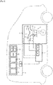
- the figure 1 illustrates a motor vehicle 1 comprising a dual-fuel internal combustion heat engine 2, and a dual-fuel supply system for the engine 2 comprising an engine control device 3 and an injector cooling device 4.
- the engine 2 comprises a cylinder 5 comprising a combustion chamber 6 fed by an intake duct 7 and connected to an exhaust duct 8.
- the engine 2 can comprise more than one cylinder, the cylinders being identical.
- the engine 2 comprises an indirect fuel injection system comprising a first injector 9 located in the intake duct 7, and a direct fuel injection system comprising a second injector 10 equipped with an injection nozzle 11 located in the intake pipe 7.
- the intake duct 7 further comprises a throttle body 12 upstream of the first injector 9 to regulate the flow of air admitted into the combustion chamber 6.
- the engine 2 further comprises a device for measuring the richness of the air/fuel mixture comprising at least one oxygen sensor 14 located in the exhaust pipe 8, in particular upstream of a pollution control device of the three-way catalyst type (not shown) in the figure.
- the oxygen sensor 14 is a lambda sensor (that is to say of the proportional type).
- the first injector 9 delivers a first fuel, for example a gaseous fuel such as liquefied petroleum gas LPG or liquefied natural gas LNG or a fuel of the liquid type, for example gasoline
- a first fuel for example a gaseous fuel such as liquefied petroleum gas LPG or liquefied natural gas LNG or a fuel of the liquid type, for example gasoline
- the second injector 10 delivers a second fuel, for example a liquid fuel such as gasoline or a fuel of the gaseous type, for example liquid LPG.
- the first fuel comprises a gaseous fuel and the second fuel comprises gasoline, which corresponds for example to the case of numerous engines operating on LPG placed on the market.
- An inlet valve 15 located between the first injector 9 and the combustion chamber 6 regulates the admission of the air/first fuel mixture or air into the combustion chamber 6.
- Motor 2 is cooled by a cooling liquid.
- the engine control device 3 controls the engine 2, in particular the first and second injectors 9, 10 and the throttle body 12 as a function in particular of the richness measuring device, of instructions from the driver of the vehicle 1 provided for example by the pedal vehicle accelerator, and the injector cooling device 4.
- the engine control device 3 comprises a first injection controller 16 controlling the first injector 9 and a second injection controller 17 controlling the second injector 10, which can be combined with each other.
- the injector cooling device 4 comprises a processing unit 18 and a memory 19 connected to the processing unit 19.
- the processing unit 18 determines a flow rate Qp of second fuel intended to be injected by the second injector 10 simultaneously with a flow rate of the first fuel when the temperature T-11 of the injection nozzle 11 of the second injector 10 is greater than a first threshold SI for a predetermined duration Tp.
- the flow of second fuel is determined to cool the nozzle 11 so that the temperature of the nozzle 11 is lower than the first threshold S1.
- the second fuel flow Qp cools the injection nozzle 11 when the combustion chamber 6 is supplied by the first injector 9.
- Maps 20, 21, 22, a transfer function H(P) of a first order filter 23, the first threshold SI and the predetermined duration Tp are saved in the memory 19.
- the interest of the maps and of the function transfer is specified below.
- the first threshold SI is for example determined from the maximum allowable temperature Tmax-11 of the nozzle 11 to operate without degrading, the maximum allowable temperature Tmax-11 generally being provided by the manufacturer of the injector 10.
- a first map 20 links a first temperature Temp1 of the injection nozzle 11 of the second injector 10 to the speed and to the load of the engine 2 according to the fuel mode of the engine.
- the load of engine 2 corresponds in a manner known per se to the torque delivered by the engine or to the average effective pressure of cylinder 5.
- a second map 21 linking a correction coefficient COEF to the temperature of the engine coolant 2 is saved in the memory 19.
- the temperature of the coolant makes it possible to estimate the temperature of the nozzle 11 more precisely than by the first mapping alone, the coolant of the nozzle 11 cooling the nozzle 11 via the intermediary of the engine cylinder head 2.
- a third map 22 connects a flow rate of the second fuel to a temperature difference and to the engine speed and load.
- the third map 22 takes into account the cooling of the nozzle 11 generated by the passage of gasoline through said nozzle.
- the transfer function H(p) models the time evolution of the temperature of the nozzle 11 when the engine 2 is not supplied with fuel, for example when the driver of vehicle 1 completely releases the accelerator pedal of vehicle 1 , for example on a downhill slope to benefit from engine braking.
- the complete release of the accelerator pedal is interpreted by the engine control device 3 as a zero setpoint of the torque delivered by the engine 1 so that the engine control device 3 cuts off the fuel injection, the device 3 controlling in generally besides the throttle housing 12 so as to close the throttle to maximize engine braking.
- the time constant of the transfer function H(p) is determined from readings of cooling duration measurements of the nozzle 11 carried out on a test bench when the engine 2 passes from an operating point where it is supplied by the first injector 9 to a point of zero fuel flow.
- the maximum cooling time of the nozzle is equal to the time necessary for the temperature of the nozzle 11 to stabilize at a temperature close to that of the cooling liquid.
- the first map 20 one begins with a first phase in which the temperature of the nozzle 11 is raised for each operating point of the engine 2 when said temperature is stabilized, the engine 2 being supplied with fuel by the second injector 11 in order to to establish a first part of the first stabilized temperature map.
- the temperature of the nozzle 11 is raised for each operating point of the engine 2 when said temperature has stabilized, the engine 2 being supplied with fuel by the first injector 9 in order to establish a second part of the first stabilized temperature map.
- the first map 20 makes it possible to estimate the temperature of the nozzle 11 as a function of the carburetion mode of the engine 2, that is to say, when the engine is supplied with fuel exclusively by the first injector (mode d indirect injection) or exclusively by the second injector (direct injection mode) and according to the duration of a changeover from indirect injection mode to direct injection mode or vice versa (transient mode).
- the evolution over time of the temperature of the nozzle 11 can be noted in a similar manner during the passage from the indirect supply mode to the direct supply mode.
- Temperature and time measurements can be performed on a test bench.
- the second map 21 is determined by measuring the temperature of the nozzle 11 calculated by the digital model for different temperatures of the coolant, the coefficient COEFF being determined by varying the cooling temperature for an engine operating point, the simulations being repeated for each operating point.
- the determination of the coefficient COEFF can be carried out from measurements carried out on an engine test bench.
- This coefficient is used to correct in a simple manner the values of the temperature of the nozzle 11 resulting from the first mapping.
- the third map aims to know the temperature of the nozzle 11 that can be obtained if, instead of operating the engine in exclusive indirect injection mode, a proportion of fuel injected in direct injection mode is combined.
- a map of the temperature of the nozzle 11 in at least partially indirect injection mode is determined by noting the temperature of the nozzle 11 during the variation of the flow rate of second fuel injected by the second injector 10 for each engine operating point, engine 2 operating in at least partially indirect injection mode.
- the temperature readings are for example taken on an engine test bench.
- the figure 2 illustrates for a given operating point the evolution of the temperature T-11 of the nozzle 11 as a function of the second fuel flow Q2, and the straight lines D1 and D2 modeling said evolution of the temperature T-11 of the nozzle 11.
- a temperature gain to be achieved so that the temperature of the nozzle 11 is less than or equal to the first threshold SI in at least partially indirect injection mode is determined by determining a temperature gain map of the nozzle 11.
- the gain map is determined by calculating the difference between each temperature of the first stabilized temperature map and the first threshold S1.
- the third map 22 includes all of the coefficients C1, D1, C2 and D2 for each operating point.
- the third map 22 makes it possible to precisely determine for each operating point a flow rate of second fuel to be injected in order to reach the temperature gain of the nozzle 11.
- the fuel flow to be injected by the second injector 10 to reach the determined temperature gain corresponds to the maximum of the values determined by the straight lines D3, D4.
- the picture 3 illustrates for a given operating point the evolution of the second fuel flow rate Q2 modeled by the straight lines D3, D4 as a function of the temperature T-11 of the nozzle 11.
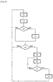
- the figure 4 shows an example of a dual-fuel fuel system control method.
- the processing unit 18 determines a first temperature of the nozzle 11 from the first map 20, the speed and the load of the engine 2, and the time elapsed since the moment of the mode switchover. direct feed mode to indirect feed mode.
- the engine speed and load 2 are for example transmitted to the processing unit by the engine control device 3.
- the processing unit 18 determines the value of the correction coefficient COEF from the temperature of the coolant provided for example by the engine control device 3.
- the processing unit 18 determines a second temperature of injection nozzle 11 by multiplying the correction coefficient COEFF by the first temperature of nozzle 11.
- the temperature of the nozzle 11 is known while the engine is operating without any injection of fuel through said nozzle.
- the temperature of nozzle 11 tends to increase with time spent in pure indirect injection mode.
- the temporal evolution profile of said temperature depends on the regime-load operating point of the engine, which depends in particular on the depression of the accelerator pedal of the vehicle.
- the processing unit 18 multiplies the second temperature by the first order filter 23 (step 33), the temperature T-11 of the nozzle 11 being equal to the second temperature multiplied by the first order filter 23.
- the temperature T-11 of the nozzle 11 is equal to the second temperature.
- the motor control device 3 provides, for example, motor power information.
- a step 34 the processing unit 18 compares the temperature T-11 of the nozzle 11 with the first threshold S1.
- the first threshold SI is for example equal to the maximum admissible temperature Tmax-11 plus a hysteresis value.
- step 34 If the temperature T-11 of the nozzle 11 is lower than the first threshold SI (step 34), the engine 2 remains supplied by the first injector 9.
- the processing unit 18 determines the flow rate Q2 of second fuel to be injected to cool the second injector 11 from the temperature T-11 of the nozzle, the speed and the load of the engine 2, and the third map 22 (step 35).
- the hysteresis makes it possible to avoid untimely switching when the operating point of motor 2 is around a boundary zone between the indirect engine supply mode and the dual-fuel supply mode of engine 2 (simultaneous injection of the first and second fuels into the combustion chamber 6).
- the hysteresis value is for example determined by calibration tests on vehicle 1.
- the processing unit 18 transmits the second fuel flow rate Q2 to the engine control device 3.
- the first injection controller 16 controls the first injector 9 and the second injection controller 17 controls the second injector 10 so that the second injector 10 injects the flow Q2 of second fuel, the flow of first fuel injected by the first injector 9 being injected so that the richness setpoint of the air mixture and the first and second fuels is equal to 1.
- the engine 2 is supplied by the first and second injectors 9, 10 simultaneously in dual-fuel supply mode (“dual-fuel” mode).
- the flow of first fuel can be injected in an open loop, and the flow of second fuel is adjusted by adding to a prepositioning value an injection quantity correction capable of regulating the richness around the stoichiometric value.
- the processing unit 18 controls the device 3 from so that the second injector 10 is cut off.
- the first injection controller 16 drives the first injector 9 so that the richness setpoint of the air and first fuel mixture is equal to 1, the temperature of the nozzle 11 being lower than the maximum allowable temperature (step 38). The process then continues at step 30.
- step 36 If the temperature T-11 of the nozzle 11 is greater than the second threshold S2, the method goes to step 36.
- the processing unit 18 determines the temperature T-11 of the nozzle 11, and if necessary determines and injects the flow rate Q2 of second fuel at regular time intervals, for example at each injection cycle of the first fuel equal for example to 10 ms.
- the condition on the predetermined duration Tp before switching to dual-fuel supply mode makes it possible to filter out a rapid transient phase from the estimation of the temperature of the nozzle 11.
- the second threshold S2 makes it possible to inject the second fuel to cool the nozzle 11 to a temperature lower than that of the first threshold S1 to prevent incessant switching of the supply mode as the temperature of the nozzle 11 evolves.
- the control method of the bi-fuel supply system makes it possible to inject the necessary quantity of second fuel to cool the nozzle 11 so that it does not deteriorate while reducing the emissions of polluting residues, in particular carbon dioxide.
Abstract
L'invention concerne un procédé de commande d'un système d'alimentation à bicarburation d'un moteur thermique (2) à combustion interne pour véhicule automobile (1) comprenant au moins un premier injecteur (9) situé dans une conduite d'admission (7) d'au moins une chambre de combustion (6) dudit moteur, et un deuxième injecteur (10) comprenant une buse d'injection (11) située dans ladite chambre de combustion. Ce procédé comprend l'injection d'un premier carburant par le premier injecteur dans la conduite d'admission pour faire fonctionner ledit moteur et l'injection simultanée d'un deuxième carburant par le deuxième injecteur dans la chambre de combustion est proposé.The invention relates to a method for controlling a dual-fuel supply system of an internal combustion heat engine (2) for a motor vehicle (1) comprising at least a first injector (9) located in an intake duct (7) of at least one combustion chamber (6) of said engine, and a second injector (10) comprising an injection nozzle (11) located in said combustion chamber. This method comprises the injection of a first fuel by the first injector into the intake pipe to operate said engine and the simultaneous injection of a second fuel by the second injector into the combustion chamber is proposed.
Le deuxième carburant est injecté lorsque la température de la buse d'injection du deuxième injecteur est supérieure à un premier seuil pendant une durée prédéterminée (Tp), le débit de deuxième carburant injecté étant déterminé pour refroidir la buse d'injection de sorte que la température de la buse d'injection soit inférieure à un deuxième seuil.

Description
La présente invention concerne les moteurs thermiques à bicarburation de véhicules automobiles, et plus particulièrement un procédé de commande d'un système d'alimentation à bicarburation d'un moteur thermique et une unité de traitement mettant en œuvre le procédé de commande.The present invention relates to dual-fuel heat engines of motor vehicles, and more particularly to a method for controlling a dual-fuel supply system of a heat engine and a processing unit implementing the control method.
Un moteur thermique à combustion interne de véhicule automobile peut être équipé de deux systèmes d'injection de carburant distincts comprenant généralement un système d'injection directe et un système d'injection indirecte pour alimenter le moteur en carburants de deux types différents.A motor vehicle internal combustion heat engine can be equipped with two separate fuel injection systems generally comprising a direct injection system and an indirect injection system to supply the engine with fuels of two different types.
Le système d'injection directe introduit un premier type de carburant, généralement de l'essence, dans les chambres de combustion du moteur, et le système d'injection indirecte introduit un deuxième type de carburant, généralement du gaz de pétrole liquéfié GPL ou du gaz naturel liquéfié GNL, en amont des soupapes d'admission du moteur, par exemple dans des pipes d'admission d'air de la culasse du moteur ou encore dans un répartiteur d'admission du moteur.The direct injection system introduces a first type of fuel, generally gasoline, into the combustion chambers of the engine, and the indirect injection system introduces a second type of fuel, generally liquefied petroleum gas LPG or liquefied natural gas LNG, upstream of the engine intake valves, for example in air intake pipes of the engine cylinder head or even in an engine intake distributor.
Lorsque le moteur est alimenté par le système d'injection directe, des injecteurs injectent le premier type de carburant dans la chambre de combustion.When the engine is fed by the direct injection system, injectors inject the first type of fuel into the combustion chamber.
En traversant chaque injecteur, le premier carburant refroidit chacun des injecteurs de sorte que la température des injecteurs reste inférieure à leur température maximale admissible, empêchant leur détérioration.Passing through each injector, the first fuel cools each of the injectors so that the temperature of the injectors remains below their maximum allowable temperature, preventing their deterioration.
Lorsque le moteur est alimenté par le système d'injection indirecte, les injecteurs du système d'injection directe se réchauffent sous l'effet de la température générée dans la chambre de combustion du moteur, mais ne sont plus refroidis par le premier carburant.When the engine is fed by the indirect injection system, the injectors of the direct injection system heat up under the effect of the temperature generated in the combustion chamber of the engine, but are no longer cooled by the first fuel.
La température des injecteurs du système d'injection directe augmente fortement de sorte que, dans certaines conditions, notamment sur certains points de fonctionnement très chargés du moteur et après une certaine durée, la température des buses des injecteurs peut en arriver à excéder la température maximale admissible des buses.The temperature of the injectors of the direct injection system increases sharply so that, under certain conditions, in particular on certain highly loaded operating points of the engine and after a certain period of time, the temperature of the nozzles of the injectors may come to exceed the maximum temperature allowable nozzles.
On pourra se référer au document
Lorsque le moteur fonctionne en injection indirecte et que la température des injecteurs d'injection directe devient excessive, le système d'injection indirecte est coupé et le système d'injection direct est mis en route pour alimenter le moteur de manière exclusive.When the engine is running on indirect injection and the temperature of the direct injection injectors becomes excessive, the indirect injection system is shut down and the direct injection system is started up to supply the engine exclusively.
Le procédé divulgué permet de baisser la température des injecteurs du système d'injection direct.The method disclosed makes it possible to lower the temperature of the injectors of the direct injection system.
Cependant, lorsque le moteur est alimenté en essence par le système d'injection direct, les émanations de résidus de combustion, notamment les émanations de dioxyde de carbone, sont supérieures à celles qui sont rejetées lorsque le moteur est alimenté par le système d'injection indirect délivrant un carburant gazeux.However, when the engine is supplied with gasoline by the direct injection system, the fumes of combustion residues, in particular the fumes of carbon dioxide, are greater than those which are released when the engine is supplied by the injection system. indirect delivering a gaseous fuel.
Les émanations de dioxyde de carbone sont supérieures d'environ 10% quand l'alimentation en essence est exclusive.Carbon dioxide emissions are about 10% higher when gasoline fueling is exclusive.
Le document
L'injection simultanée de carburant à partir des injecteurs des systèmes d'injection directe et indirecte permet de diminuer la température des injecteurs du système d'injection directe.The simultaneous injection of fuel from the injectors of the direct and indirect injection systems makes it possible to reduce the temperature of the injectors of the direct injection system.
Cependant, ce document ne divulgue pas une méthode précise de réglage de la quantité de deuxième carburant à injecter pour contrôler la température des injecteurs du systèmes d'injection directe.However, this document does not disclose a precise method for adjusting the quantity of second fuel to be injected in order to control the temperature of the injectors of the direct injection systems.
Si la quantité de deuxième carburant injectée est trop faible, lesdits injecteurs sont insuffisamment refroidis, et si la quantité de deuxième carburant injectée est trop élevée, le refroidissement est plus que suffisant, mais les émanations de dioxyde de carbone augmentent indument.If the quantity of second fuel injected is too low, said injectors are insufficiently cooled, and if the quantity of second fuel injected is too high, the cooling is more than sufficient, but the carbon dioxide emissions increase unduly.
Il est donc proposé de pallier tout ou partie des inconvénients précités et, en particulier, d'empêcher la dégradation des injecteurs du système d'injection direct tout en minimisant les émanations de résidus de combustion.It is therefore proposed to overcome all or part of the aforementioned drawbacks and, in particular, to prevent the degradation of the injectors of the direct injection system while minimizing the emissions of combustion residues.
Au vu de ce qui précède, l'invention propose un procédé de commande d'un système d'alimentation à bicarburation d'un moteur thermique à combustion interne pour véhicule automobile comprenant au moins un premier injecteur situé dans une conduite d'admission d'au moins une chambre de combustion dudit moteur, et un deuxième injecteur comprenant une buse d'injection située dans ladite chambre de combustion, le procédé comprenant l'injection d'un premier carburant par le premier injecteur dans la conduite d'admission pour faire fonctionner ledit moteur et l'injection simultanée d'un deuxième carburant par le deuxième injecteur dans la chambre de combustion.In view of the foregoing, the invention proposes a method for controlling a dual-fuel supply system of a thermal internal combustion engine for a motor vehicle comprising at least a first injector located in an intake duct of at least one combustion chamber of said engine, and a second injector comprising an injection nozzle located in said combustion chamber, the method comprising injecting a first fuel through the first injector into the intake pipe to operate said engine and the simultaneous injection of a second fuel by the second injector into the combustion chamber.
Le deuxième carburant est injecté lorsque la température de la buse d'injection du deuxième injecteur est supérieure à un premier seuil pendant une durée prédéterminée, le débit de deuxième carburant injecté étant déterminé pour refroidir la buse d'injection de sorte que la température de la buse d'injection soit inférieure à un deuxième seuil.The second fuel is injected when the temperature of the injection nozzle of the second injector is greater than a first threshold for a predetermined duration, the flow rate of the second injected fuel being determined to cool the injection nozzle so that the temperature of the injection nozzle is below a second threshold.
Selon une caractéristique, la détermination de la température de la buse d'injection du deuxième injecteur comprend :
- la détermination d'une première température de la buse d'injection à partir du régime et de la charge du moteur, et du mode de carburation du moteur,
- la détermination d'une deuxième température de la buse d'injection à partir de la première température de la buse d'injection et de la température d'un liquide de refroidissement du moteur,
- la correction de la deuxième température de la buse d'injection lorsque le moteur n'est pas alimenté en carburant, la température de la buse étant égale à la deuxième température de la buse ou à la deuxième température corrigée de la buse.
- the determination of a first temperature of the injection nozzle from the speed and the load of the engine, and the fuel mode of the engine,
- determining a second temperature of the injection nozzle from the first temperature of the injection nozzle and the temperature of an engine coolant,
- the correction of the second temperature of the injection nozzle when the engine is not supplied with fuel, the nozzle temperature being equal to the second nozzle temperature or the second corrected nozzle temperature.
De préférence, au moins une première cartographie relie la première température de la buse d'injection au régime et à la charge du moteur, selon le mode de carburation du moteur.Preferably, at least a first map links the first temperature of the injection nozzle to the speed and to the load of the engine, according to the fuel mode of the engine.
Avantageusement, au moins une deuxième cartographie relie un coefficient de correction à la température du liquide de refroidissement du moteur, la deuxième température de la buse d'injection étant égale au coefficient de correction multiplié par la première température de la buse d'injection.Advantageously, at least one second map links a correction coefficient to the temperature of the engine coolant, the second temperature of the injection nozzle being equal to the correction coefficient multiplied by the first temperature of the injection nozzle.
Selon une autre caractéristique, la détermination de la deuxième température corrigée de la buse comprend la multiplication de la deuxième température de la buse par un filtre du premier ordre modélisant l'évolution temporelle de la température de la buse lorsque le moteur n'est pas alimenté en carburant.According to another characteristic, the determination of the second corrected temperature of the nozzle comprises the multiplication of the second temperature of the nozzle by a first order filter modeling the temporal evolution of the temperature of the nozzle when the motor is not supplied in fuel.
De préférence, le débit du deuxième carburant injecté est déterminé à partir de la différence de température entre la température de la buse et d'une température maximale admissible de la buse, et du régime et de la charge du moteur.Preferably, the flow rate of the second fuel injected is determined from the temperature difference between the temperature of the nozzle and a maximum admissible temperature of the nozzle, and from the speed and the load of the engine.
Avantageusement, au moins une troisième cartographie relie le débit du deuxième carburant injecté à la différence de température, et au régime et à la charge du moteur.Advantageously, at least a third map links the flow rate of the second injected fuel to the temperature difference, and to the engine speed and load.
De préférence, lorsque le deuxième carburant est injecté, le débit de premier carburant injecté est réduit et le débit du deuxième carburant est ajusté de sorte que la richesse du mélange d'air et des premier et deuxième carburants soit égale à 1.Preferably, when the second fuel is injected, the flow rate of the first fuel injected is reduced and the flow rate of the second fuel is adjusted so that the richness of the mixture of air and of the first and second fuels is equal to 1.
Avantageusement, la température de la buse d'injection du deuxième injecteur est déterminée à chaque cycle moteur.Advantageously, the temperature of the injection nozzle of the second injector is determined at each engine cycle.
L'invention a également pour objet une unité de traitement pour système d'alimentation à bicarburation d'un moteur thermique à combustion interne pour véhicule automobile.The invention also relates to a processing unit for a dual-fuel supply system of an internal combustion heat engine for a motor vehicle.
L'unité de traitement est configurée pour déterminer un débit d'un deuxième carburant et injecter ledit débit, le deuxième carburant étant destiné à être injecté par au moins un deuxième injecteur comprenant une buse d'injection située dans au moins une chambre de combustion du moteur lorsque au moins un premier injecteur situé dans une conduite d'admission de la chambre de combustion injecte un premier carburant dans la conduite d'admission pour faire fonctionner ledit moteur, le deuxième carburant étant injecté simultanément avec le premier carburant lorsque la température de la buse d'injection du deuxième injecteur est supérieure à un premier seuil pendant une durée prédéterminée, le débit de deuxième carburant injecté étant déterminé pour refroidir la buse d'injection de sorte que la température de la buse d'injection soit inférieure à un deuxième seuil.The processing unit is configured to determine a flow rate of a second fuel and inject said flow rate, the second fuel being intended to be injected by at least one second injector comprising an injection nozzle located in at least one combustion chamber of the engine when at least one first injector located in an intake pipe of the combustion chamber injects a first fuel into the intake pipe to operate said engine, the second fuel being injected simultaneously with the first fuel when the temperature of the injection nozzle of the second injector is greater than a first threshold for a predetermined duration, the flow rate of the second injected fuel being determined to cool the injection nozzle so that the temperature of the injection nozzle is below a second threshold.
D'autres buts, caractéristiques et avantages de l'invention apparaîtront à la lecture de la description suivante, donnée uniquement à titre d'exemple non limitatif, et faite en référence aux dessins annexés sur lesquels :
- [
Fig 1 ] illustre schématiquement un véhicule automobile doté d'une unité de traitement selon l'invention, - [
Fig 2 ] illustre un exemple de modélisation de l'évolution de la température de la buse d'injection du deuxième injecteur en fonction du débit de deuxième carburant selon l'invention, - [
Fig 3 ] illustre un exemple de modélisation de l'évolution du débit de deuxième carburant en fonction de la température de la buse d'injection du deuxième injecteur selon l'invention, et - [
Fig 4 ] illustre un exemple de procédé de commande du système d'alimentation à bicarburation selon l'invention.
- [
Fig 1 ] schematically illustrates a motor vehicle equipped with a processing unit according to the invention, - [
Fig 2 ] illustrates an example of modeling the evolution of the temperature of the injection nozzle of the second injector as a function of the flow rate of the second fuel according to the invention, - [
Fig.3 ] illustrates an example of modeling the evolution of the second fuel flow as a function of the temperature of the injection nozzle of the second injector according to the invention, and - [
Fig 4 ] illustrates an example of a method for controlling the dual-fuel supply system according to the invention.
La
Dans ce qui suit, on considère que le moteur 2 comprend un cylindre 5 comprenant une chambre de combustion 6 alimentée par une conduite d'admission 7 et reliée à une conduite d'échappement 8.In what follows, it is considered that the engine 2 comprises a cylinder 5 comprising a combustion chamber 6 fed by an intake duct 7 and connected to an
Bien entendu, le moteur 2 peut comprendre plus d'un cylindre, les cylindres étant identiques.Of course, the engine 2 can comprise more than one cylinder, the cylinders being identical.
Le moteur 2 comprend un système d'injection de carburant indirect comprenant un premier injecteur 9 situé dans la conduite d'admission 7, et un système d'injection de carburant direct comprenant un deuxième injecteur 10 équipé d'une buse d'injection 11 située dans la conduite d'admission 7.The engine 2 comprises an indirect fuel injection system comprising a
La conduite d'admission 7 comprend en outre un boîtier papillon 12 en amont du premier injecteur 9 pour réguler le débit d'air admis dans la chambre de combustion 6.The intake duct 7 further comprises a
Le moteur 2 comprend en outre un dispositif de mesure de richesse du mélange air/carburant comprenant au moins une sonde à oxygène 14 située dans la conduite d'échappement 8, notamment en amont d'un dispositif de dépollution de type catalyseur trois voies (non représenté) sur la figure.The engine 2 further comprises a device for measuring the richness of the air/fuel mixture comprising at least one
De préférence, la sonde à oxygène 14 est une sonde lambda (c'est-à-dire de type proportionnel).Preferably, the
Le premier injecteur 9 délivre un premier carburant, par exemple un carburant gazeux tel que du gaz de pétrole liquéfié GPL ou du gaz naturel liquéfié GNL ou un carburant du type liquide, par exemple de l'essence, et le deuxième injecteur 10 délivre un deuxième carburant, par exemple un carburant liquide tel que de l'essence ou un carburant du type gazeux, par exemple du GPL liquide.The
On suppose par exemple dans ce qui suit que le premier carburant comprend un carburant gazeux et le deuxième carburant comprend de l'essence, ce qui correspond par exemple au cas de nombreux moteurs fonctionnant au GPL mis sur le marché.It is assumed for example in what follows that the first fuel comprises a gaseous fuel and the second fuel comprises gasoline, which corresponds for example to the case of numerous engines operating on LPG placed on the market.
Une soupape d'admission 15 située entre le premier injecteur 9 et la chambre de combustion 6 régule l'admission du mélange air/premier carburant ou de l'air dans la chambre de combustion 6.An
Le moteur 2 est refroidi par un liquide de refroidissement.Motor 2 is cooled by a cooling liquid.
Le dispositif de contrôle moteur 3 pilote le moteur 2, notamment les premier et deuxième injecteurs 9, 10 et le boîtier papillon 12 en fonction notamment du dispositif de mesure de richesse, d'instructions du conducteur du véhicule 1 fournies par exemple par la pédale d'accélérateur du véhicule, et du dispositif de refroidissement d'injecteurs 4.The engine control device 3 controls the engine 2, in particular the first and
Le dispositif de contrôle moteur 3 comprend un premier contrôleur 16 d'injection pilotant le premier injecteur 9 et un deuxième contrôleur 17 d'injection pilotant le deuxième injecteur 10, qui peuvent être confondus l'un avec l'autre.The engine control device 3 comprises a
Le dispositif de refroidissement d'injecteurs 4 comprend une unité de traitement 18 et une mémoire 19 reliée à l'unité de traitement 19.The injector cooling device 4 comprises a
L'unité de traitement 18 détermine un débit Qp de deuxième carburant destiné à être injecté par le deuxième injecteur 10 simultanément avec un débit du premier carburant lorsque la température T-11 de la buse d'injection 11 du deuxième injecteur 10 est supérieure à un premier seuil SI pendant une durée prédéterminée Tp.The
Le débit de deuxième carburant est déterminé pour refroidir la buse 11 de sorte que la température de la buse 11 soit inférieure au premier seuil S1.The flow of second fuel is determined to cool the
Le débit Qp de deuxième carburant refroidit la buse d'injection 11 lorsque la chambre de combustion 6 est alimentée par le premier injecteur 9.The second fuel flow Qp cools the
Des cartographies 20, 21, 22, une fonction de transfert H(P) d'un filtre 23 de premier ordre, le premier seuil SI et la durée prédéterminée Tp sont sauvegardés dans la mémoire 19. L'intérêt des cartographies et de la fonction de transfert est précisé par la suite.
Le premier seuil SI est par exemple déterminé à partir de la température maximale admissible Tmax-11 de la buse 11 pour fonctionner sans se dégrader, la température maximale admissible Tmax-11 étant généralement fournie par le constructeur de l'injecteur 10.The first threshold SI is for example determined from the maximum allowable temperature Tmax-11 of the
Une première cartographie 20 relie une première température Temp1 de la buse d'injection 11 du deuxième injecteur 10 au régime et à la charge du moteur 2 selon le mode de carburation du moteur.A
La charge du moteur 2 correspond de manière connue en soi au couple délivré par le moteur ou à la pression moyenne effective du cylindre 5.The load of engine 2 corresponds in a manner known per se to the torque delivered by the engine or to the average effective pressure of cylinder 5.
Une deuxième cartographie 21 reliant un coefficient COEF de correction à la température du liquide de refroidissement du moteur 2 est sauvegardée dans la mémoire 19.A
La prise en compte de la température du liquide de refroidissement permet d'estimer la température de la buse 11 de manière plus précise que par la seule première cartographie, le liquide de refroidissement de la buse 11 refroidissant la buse 11 par l'intermédiaire de la culasse du moteur 2.Taking into account the temperature of the coolant makes it possible to estimate the temperature of the
Une troisième cartographie 22 relie un débit du deuxième carburant à une différence de température et au régime et à la charge du moteur.A
La troisième cartographie 22 prend en compte le refroidissement de la buse 11 engendré par le passage d'essence à travers ladite buse.The
La détermination des première, deuxième et troisième cartographies est détaillée dans ce qui suit.The determination of the first, second and third maps is detailed in the following.
La fonction de transfert H(p) modélise l'évolution temporelle de la température de la buse 11 lorsque le moteur 2 n'est pas alimenté en carburant, par exemple lorsque le conducteur du véhicule 1 relâche complètement la pédale d'accélérateur du véhicule 1, par exemple dans une pente descendante pour bénéficier du frein moteur.The transfer function H(p) models the time evolution of the temperature of the
Le relâchement complet de la pédale d'accélérateur est interprété par le dispositif de contrôle moteur 3 comme une consigne nulle du couple délivré par le moteur 1 de sorte que le dispositif de contrôle moteur 3 coupe l'injection de carburant, le dispositif 3 pilotant en outre généralement le boîtier papillon 12 de manière à fermer le papillon pour maximiser le frein moteur.The complete release of the accelerator pedal is interpreted by the engine control device 3 as a zero setpoint of the torque delivered by the engine 1 so that the engine control device 3 cuts off the fuel injection, the device 3 controlling in generally besides the
L'absence de combustion dans la chambre de combustion 6 et le balayage du cylindre 5 par de l'air s'écoulant à travers le boîtier papillon 12 fermé refroidissent la buse 11.The absence of combustion in the combustion chamber 6 and the scavenging of the cylinder 5 by air flowing through the
La constante de temps de la fonction de transfert H(p) est déterminée à partir de relevés de mesures de durée de refroidissement de la buse 11 réalisées sur banc d'essai lorsque le moteur 2 passe d'un point de fonctionnement où il est alimenté par le premier injecteur 9 à un point de débit de carburant nul.The time constant of the transfer function H(p) is determined from readings of cooling duration measurements of the
Pour chaque point de fonctionnement stabilisé du moteur 2 défini par un couple régime et charge, et pour différentes températures connues stabilisées de la buse 11, la pédale d'accélérateur est complètement relâchée.For each stabilized operating point of the engine 2 defined by a speed and load pair, and for different stabilized known temperatures of the
La durée de refroidissement maximale de la buse est égale à la durée nécessaire pour que la température de la buse 11 se stabilise à une température proche de celle du liquide de refroidissement.The maximum cooling time of the nozzle is equal to the time necessary for the temperature of the
A présent sont détaillées les étapes d'obtention des trois cartographies 20, 21 et 22.The steps for obtaining the three
Pour obtenir la première cartographie 20, on commence par une première phase dans laquelle la température de la buse 11 est relevée pour chaque point de fonctionnement du moteur 2 lorsque ladite température est stabilisée, le moteur 2 étant alimenté en carburant par le deuxième injecteur 11 afin d'établir une première partie de la première cartographie de température stabilisée.To obtain the
En outre, dans une deuxième phase, la température de la buse 11 est relevée pour chaque point de fonctionnement du moteur 2 lorsque ladite température est stabilisée, le moteur 2 étant alimenté en carburant par le premier injecteur 9 afin d'établir une deuxième partie de la première cartographie de température stabilisée.In addition, in a second phase, the temperature of the
Lorsque les première et deuxième parties de la première cartographie de température stabilisée sont établies, on passe à une troisième phase dans laquelle, pour chaque point de fonctionnement, le moteur 2 est tout d'abord alimenté par le deuxième injecteur 10. Lorsque la température de la buse 11 a atteint la valeur stabilisée correspondant audit point de fonctionnement déterminée par la première cartographie de température stabilisée, le deuxième injecteur 10 est coupé et le premier injecteur 9 est actionné pour alimenter le moteur 2. Le basculement du premier vers le deuxième injecteur s'effectue brutalement.When the first and second parts of the first map of stabilized temperature are established, we pass to a third phase in which, for each operating point, the engine 2 is first of all supplied by the
Puis, l'évolution temporelle de la température de la buse 11 est relevée jusqu'à ce que la température de la buse 11 atteigne la température correspondante de la deuxième cartographie de température stabilisée. On obtient ainsi une troisième partie de la cartographie qui donne la température de la buse 11 lors d'une phase transitoire de mode de carburation.Then, the evolution over time of the temperature of the
En résumé, la première cartographie 20 permet d'estimer la température de la buse 11 en fonction du mode de carburation du moteur 2, c'est-à-dire, lorsque le moteur est alimenté en carburant exclusivement par le premier injecteur (mode d'injection indirecte) ou exclusivement par le deuxième injecteur (mode d'injection directe) et selon la durée d'un basculement du mode d'injection indirecte au mode d'injection directe ou inversement (mode transitoire).In summary, the
Afin de déterminer la première cartographie 20 de manière plus précise, l'évolution temporelle de la température de la buse 11 peut être relevée de manière similaire lors du passage du mode d'alimentation indirect vers le mode d'alimentation direct.In order to determine the
Les mesures de températures et de durées peuvent être réalisées sur un banc d'essai.Temperature and time measurements can be performed on a test bench.
A présent la détermination de la deuxième cartographie 21 est détaillée.Now the determination of the
Afin de simplifier la détermination de la deuxième cartographie 21, un modèle thermique numérique de la culasse du moteur 2 est réalisé.In order to simplify the determination of the
La deuxième cartographie 21 est déterminée en mesurant la température de la buse 11 calculée par le modèle numérique pour différentes températures du liquide de refroidissement, le coefficient COEFF étant déterminé en faisant varier la température de refroidissement pour un point de fonctionnement du moteur, les simulations étant réitérées pour chaque point de fonctionnement.The
En variante, la détermination du coefficient COEFF peut être réalisée à partir de mesures effectuées sur un banc d'essai moteur.As a variant, the determination of the coefficient COEFF can be carried out from measurements carried out on an engine test bench.
Ce coefficient sert à corriger de manière simple les valeurs de la température de la buse 11 issues de la première cartographie. En variante, il est aussi possible de faire toutes les mesures de la première cartographie en balayant les différentes valeurs possibles de température de liquide de refroidissement en plus des valeurs de régime et de charge. Cela est plus fastidieux.This coefficient is used to correct in a simple manner the values of the temperature of the
La troisième cartographie vise à connaître la température de la buse 11 que l'on peut obtenir si, au lieu de faire fonctionner le moteur en mode d'injection indirecte exclusive, on combine une proportion de carburant injecté en mode d'injection directe.The third map aims to know the temperature of the
Pour déterminer la troisième cartographie 22, une cartographie de la température de la buse 11 en mode d'injection au moins partiellement indirecte est déterminée en relevant la température de la buse 11 lors de la variation du débit de deuxième carburant injectée par le deuxième injecteur 10 pour chaque point de fonctionnement du moteur, le moteur 2 fonctionnant en mode d'injection au moins partiellement indirecte.To determine the
Les relevés de température sont par exemple effectués sur un banc d'essai moteur.The temperature readings are for example taken on an engine test bench.
A partir des relevés de température obtenus et pour chaque point de fonctionnement du moteur, l'évolution de la température de la buse 11 en fonction du débit de deuxième carburant injecté est modélisée par deux droites D1 et D2 ayant pour équation : ![]()
![]()
les coefficients A1, B1, C1 et D1 étant des constantes.From the temperature readings obtained and for each engine operating point, the evolution of the temperature of the ![]()
![]()
the coefficients A1, B1, C1 and D1 being constants.
La
Un gain en température à atteindre pour que la température de la buse 11 soit inférieure ou égale au premier seuil SI en mode d'injection au moins partiellement indirecte est déterminé en déterminant une cartographie de gain en température de la buse 11. La cartographie de gain est déterminée en calculant la différence entre chaque température de la première cartographie de température stabilisée et le premier seuil S1.A temperature gain to be achieved so that the temperature of the
A partir des droites D1 et D2 et de la cartographie de gain en température, pour chaque point de fonctionnement du moteur 2, l'évolution du débit de deuxième carburant Q2 en fonction du gain en température de la buse 11 est modélisée par deux droites D3 et D4 ayant pour équation : ![]()
![]()
les coefficients C1, D1, C2 et D2 étant des constantes.From the straight lines D1 and D2 and the temperature gain map, for each operating point of the engine 2, the evolution of the flow rate of second fuel Q2 as a function of the temperature gain of the ![]()
![]()
the coefficients C1, D1, C2 and D2 being constants.
La troisième cartographie 22 comprend l'ensemble des coefficients C1, D1, C2 et D2 pour chaque point de fonctionnement.The
La troisième cartographie 22 permet de déterminer précisément pour chaque point de fonctionnement un débit de deuxième carburant à injecter pour atteindre le gain de température de la buse 11.The
Le débit d'essence à injecter par le deuxième injecteur 10 pour atteindre le gain de température déterminé correspond au maximum des valeurs déterminées par les droites D3, D4.The fuel flow to be injected by the
La
La
On suppose que les première, deuxième et troisième cartographies 20, 21 et 22, la fonction de transfert H(P) du filtre 23, le premier seuil SI et la durée prédéterminée Tp sont sauvegardés dans la mémoire 19.It is assumed that the first, second and
On suppose qu'un basculement du mode d'alimentation direct au mode d'alimentation indirect se produit, l'instant de basculement étant sauvegardé par l'unité de traitement 18.It is assumed that a switchover from the direct supply mode to the indirect supply mode occurs, the switchover instant being saved by the
Par exemple, sur un moteur fonctionnant à l'essence en injection directe et au GPL en injection indirecte, cela se produit quelques secondes après le démarrage du moteur à l'essence, notamment pour des raisons légales. Dans la suite du parcours du véhicule, si la quantité de carburant GPL dans le réservoir concerné le permet, le dispositif de contrôle moteur 3 tend à privilégier le mode de fonctionnement du moteur en mode d'injection indirecte de GPL qui minimise les émissions de polluants.For example, on an engine running on gasoline with direct injection and LPG with indirect injection, this happens a few seconds after starting the gasoline engine, in particular for legal reasons. In the rest of the journey of the vehicle, if the quantity of LPG fuel in the tank concerned allows it, the engine control device 3 tends to favor the operating mode of the engine in indirect injection mode of LPG which minimizes the emissions of pollutants .
Durant une étape 30, l'unité de traitement 18 détermine une première température de la buse 11 à partir de la première cartographie 20, du régime et de la charge du moteur 2, et de la durée écoulée depuis l'instant du basculement du mode d'alimentation direct au mode d'alimentation indirect.During a
Le régime et la charge du moteur 2 sont par exemple transmis à l'unité de traitement par le dispositif de contrôle moteur 3.The engine speed and load 2 are for example transmitted to the processing unit by the engine control device 3.
Puis, dans une étape 31, l'unité de traitement 18 détermine la valeur du coefficient COEF de correction à partir de la température du liquide de refroidissement fournie par exemple par le dispositif de contrôle moteur 3. L'unité de traitement 18 détermine une deuxième température de la buse 11 d'injection en multipliant le coefficient COEFF de correction par la première température de la buse 11.Then, in a
A ce stade, on connaît la température de la buse 11 pendant que le moteur fonctionne sans aucune injection de carburant à travers ladite buse. La température de la buse 11 tend à augmenter avec le temps passé en mode d'injection indirecte pure. Le profil d'évolution temporelle de ladite température dépend du point de fonctionnement régime -charge du moteur, qui dépend notamment de l'enfoncement de la pédale d'accélérateur du véhicule.At this stage, the temperature of the
Cependant il se peut aussi que, pendant que le moteur fonctionne dans ce mode d'injection indirecte, le conducteur relève brutalement le pied de la pédale d'accélérateur, par exemple si le véhicule s'engage sur une pente descendante dans laquelle le conducteur souhaite bénéficier du frein moteur. La coupure d'injection de carburant tend alors, au contraire, à refroidir la température des injecteurs. Le procédé tient compte d'un tel événement pour corriger l'évaluation de la température da la buse 11.However, it is also possible that, while the engine is operating in this indirect injection mode, the driver suddenly takes his foot off the accelerator pedal, for example if the vehicle is entering a downward slope on which the driver wishes benefit from engine braking. Fuel injection cut-off then tends, on the contrary, to cool the temperature of the injectors. The method takes account of such an event to correct the evaluation of the temperature of the
Si le moteur 2 n'est pas alimenté en carburant (étape 32), l'unité de traitement 18 multiplie la deuxième température par le filtre du premier ordre 23 (étape 33), la température T-11 de la buse 11 étant égale à la deuxième température multipliée par le filtre du premier ordre 23.If the engine 2 is not supplied with fuel (step 32), the
Si le moteur 2 est alimenté en carburant (étape 32), la température T-11 de la buse 11 est égale à la deuxième température.If the engine 2 is supplied with fuel (step 32), the temperature T-11 of the
Le dispositif de contrôle moteur 3 fournit par exemple l'information d'alimentation du moteur.The motor control device 3 provides, for example, motor power information.
Dans une étape 34, l'unité de traitement 18 compare la température T-11 de la buse 11 au premier seuil S1.In a
Le premier seuil SI est par exemple égal à la température maximale admissible Tmax-11 plus une valeur d'hystérésis.The first threshold SI is for example equal to the maximum admissible temperature Tmax-11 plus a hysteresis value.
Si la température T-11 de la buse 11 est inférieure au premier seuil SI (étape 34), le moteur 2 reste alimenté par le premier injecteur 9.If the temperature T-11 of the
Si la température T-11 de la buse 11 est supérieure au premier seuil SI (étape 34) pendant la durée prédéterminée Tp, l'unité de traitement 18 détermine le débit Q2 de deuxième carburant à injecter pour refroidir le deuxième injecteur 11 à partir de la température T-11 de la buse, du régime et de la charge du moteur 2, et de la troisième cartographie 22 (étape 35).If the temperature T-11 of the
L'hystérésis permet d'éviter des basculements intempestifs lorsque le point de fonctionnement du moteur 2 se situe autour d'une zone frontière entre le mode d'alimentation indirect du moteur et le mode d'alimentation bicarburant du moteur 2 (injection simultanée des premier et deuxième carburants dans la chambre de combustion 6).The hysteresis makes it possible to avoid untimely switching when the operating point of motor 2 is around a boundary zone between the indirect engine supply mode and the dual-fuel supply mode of engine 2 (simultaneous injection of the first and second fuels into the combustion chamber 6).
La valeur d'hystérésis est par exemple déterminée par des essais de calibration sur le véhicule 1.The hysteresis value is for example determined by calibration tests on vehicle 1.
Puis, dans une étape 36, l'unité de traitement 18 transmet le débit Q2 de deuxième carburant au dispositif de contrôle moteur 3.Then, in a
Le premier contrôleur 16 d'injection pilote le premier injecteur 9 et le deuxième contrôleur 17 d'injection pilote le deuxième injecteur 10 de sorte que le deuxième injecteur 10 injecte le débit Q2 de deuxième carburant, le débit de premier carburant injecté par le premier injecteur 9 étant injecté de sorte que la consigne de richesse du mélange d'air et des premier et deuxième carburants soit égale à 1.The
Le moteur 2 est alimenté par les premier et deuxième injecteurs 9, 10 simultanément en mode d'alimentation bicarburant (mode « dual-fuel »).The engine 2 is supplied by the first and
Par exemple, le débit de premier carburant peut être injecté en boucle ouverte, et le débit de deuxième carburant est ajusté en ajoutant à une valeur de prépositionnement une correction de quantité injectée apte à réguler la richesse autour de la valeur stœchiométrique.For example, the flow of first fuel can be injected in an open loop, and the flow of second fuel is adjusted by adding to a prepositioning value an injection quantity correction capable of regulating the richness around the stoichiometric value.
Si la température T-11 de la buse 11 est inférieure à un deuxième seuil S2 égal par exemple à la température maximale admissible Tmax-11 moins la valeur d'hystérésis (étape 37), l'unité de traitement 18 pilote le dispositif 3 de sorte que le deuxième injecteur 10 soit coupé.If the temperature T-11 of the
Le premier contrôleur 16 d'injection pilote le premier injecteur 9 de sorte que la consigne de richesse du mélange d'air et premier carburant soit égale à 1, la température de la buse 11 étant inférieure à la température maximale admissible (étape 38). Le procédé se poursuit alors à l'étape 30.The
Si la température T-11 de la buse 11 est supérieure au deuxième seuil S2, le procédé passe à l'étape 36.If the temperature T-11 of the
L'unité de traitement 18 détermine la température T-11 de la buse 11, et le cas échéant détermine et injecte le débit Q2 de deuxième carburant à intervalle de temps régulier, par exemple à chaque cycle d'injection du premier carburant égal par exemple à 10 ms.The
La condition sur la durée prédéterminée Tp avant de basculer en mode d'alimentation bicarburant permet de filtrer une phase transitoire rapide de l'estimation de la température de la buse 11.The condition on the predetermined duration Tp before switching to dual-fuel supply mode makes it possible to filter out a rapid transient phase from the estimation of the temperature of the
Le deuxième seuil S2 permet d'injecteur le deuxième carburant pour refroidir la buse 11 à une température inférieure à celle du premier seuil SI pour empêcher des basculements incessants de mode d'alimentation à mesure que la température de la buse 11 évolue.The second threshold S2 makes it possible to inject the second fuel to cool the
Le procédé de commande du système d'alimentation à bicarburation permet d'injecter la quantité nécessaire de deuxième carburant pour refroidir la buse 11 de sorte qu'elle ne se détériore pas tout en réduisant les émissions de résidus polluants, notamment de dioxyde de carbone.The control method of the bi-fuel supply system makes it possible to inject the necessary quantity of second fuel to cool the
Claims (10)
Applications Claiming Priority (1)
| Application Number | Priority Date | Filing Date | Title |
|---|---|---|---|
| FR2009671A FR3114354B1 (en) | 2020-09-23 | 2020-09-23 | Method for controlling a bi-fuel supply system for a motor vehicle and associated processing unit |
Publications (1)
| Publication Number | Publication Date |
|---|---|
| EP3974636A1 true EP3974636A1 (en) | 2022-03-30 |
Family
ID=73793384
Family Applications (1)
| Application Number | Title | Priority Date | Filing Date |
|---|---|---|---|
| EP21196808.6A Pending EP3974636A1 (en) | 2020-09-23 | 2021-09-15 | Method for controlling a bi-fuelled power system for a motor vehicle and associated processing unit |
Country Status (2)
| Country | Link |
|---|---|
| EP (1) | EP3974636A1 (en) |
| FR (1) | FR3114354B1 (en) |
Citations (7)
| Publication number | Priority date | Publication date | Assignee | Title |
|---|---|---|---|---|
| US20090292443A1 (en) | 2008-05-20 | 2009-11-26 | Ford Global Technologies, Llc | Approach for reducing overheating of direct injection fuel injectors |
| US20120174891A1 (en) * | 2011-01-12 | 2012-07-12 | GM Global Technology Operations LLC | Bi-fuel engine including system and method for reducing component temperature |
| WO2013185234A1 (en) * | 2012-06-14 | 2013-12-19 | Westport Power Inc. | Fuel system protection in a multi-fuel system internal combustion engine |
| DE102012221046A1 (en) * | 2012-11-19 | 2014-05-22 | Robert Bosch Gmbh | Method for operating internal combustion engine of motor car, involves correcting intermediate value of temperature based on value of specific operational parameter of engine |
| US9453474B2 (en) * | 2013-06-12 | 2016-09-27 | Ford Global Technologies, Llc | Method for operating a direct fuel injection system |
| KR20170124358A (en) | 2016-05-02 | 2017-11-10 | 현대오트론 주식회사 | Fuel Injection Control Method for Protecting Injector Tip |
| US20190107074A1 (en) * | 2016-11-28 | 2019-04-11 | Ford Global Technologies, Llc | Methods and systems for fuel injection control |
-
2020
- 2020-09-23 FR FR2009671A patent/FR3114354B1/en active Active
-
2021
- 2021-09-15 EP EP21196808.6A patent/EP3974636A1/en active Pending
Patent Citations (7)
| Publication number | Priority date | Publication date | Assignee | Title |
|---|---|---|---|---|
| US20090292443A1 (en) | 2008-05-20 | 2009-11-26 | Ford Global Technologies, Llc | Approach for reducing overheating of direct injection fuel injectors |
| US20120174891A1 (en) * | 2011-01-12 | 2012-07-12 | GM Global Technology Operations LLC | Bi-fuel engine including system and method for reducing component temperature |
| WO2013185234A1 (en) * | 2012-06-14 | 2013-12-19 | Westport Power Inc. | Fuel system protection in a multi-fuel system internal combustion engine |
| DE102012221046A1 (en) * | 2012-11-19 | 2014-05-22 | Robert Bosch Gmbh | Method for operating internal combustion engine of motor car, involves correcting intermediate value of temperature based on value of specific operational parameter of engine |
| US9453474B2 (en) * | 2013-06-12 | 2016-09-27 | Ford Global Technologies, Llc | Method for operating a direct fuel injection system |
| KR20170124358A (en) | 2016-05-02 | 2017-11-10 | 현대오트론 주식회사 | Fuel Injection Control Method for Protecting Injector Tip |
| US20190107074A1 (en) * | 2016-11-28 | 2019-04-11 | Ford Global Technologies, Llc | Methods and systems for fuel injection control |
Also Published As
| Publication number | Publication date |
|---|---|
| FR3114354B1 (en) | 2023-03-03 |
| FR3114354A1 (en) | 2022-03-25 |
Similar Documents
| Publication | Publication Date | Title |
|---|---|---|
| FR2852631A1 (en) | Thermal engine controlling method, involves monitoring input variable/internal size of physical model based on deviation between calculated and measured values of physical size of model, to correct input variable/internal size | |
| FR3004493A1 (en) | METHOD FOR IMPLEMENTING A LEARNING FUNCTION IN A MOTOR VEHICLE AND MEANS FOR APPLYING THE METHOD | |
| EP0954689B1 (en) | Device for controlling an internal combustion engine with controlled ignition and direct injection | |
| EP3974636A1 (en) | Method for controlling a bi-fuelled power system for a motor vehicle and associated processing unit | |
| EP3574194B1 (en) | Method for controlling the nitrogen oxides emissions of an internal combustion engine | |
| FR2796670A1 (en) | Method for controlling internal combustion engine in car includes establishing efficiency estimation of combustion based on information relative to rotation regime, power, and temperature of engine | |
| FR3101673A1 (en) | Method of adjusting the richness of a spark-ignition internal combustion engine | |
| EP3816427B1 (en) | Method for diagnosing a gas leak from a low-pressure exhaust gas partial recirculation circuit of an internal combustion engine | |
| EP1375880A1 (en) | Method and system for controlling an internal combustion engine | |
| FR2890112A1 (en) | Diesel engine e.g. homogenous charge compression ignition engine, operation controlling system for motor vehicle, has control unit for controlling exhaust gas recirculation loop based on determined noise level | |
| FR2916229A1 (en) | Pollutant e.g. soot, emission controlling method for motor vehicle, involves estimating quantity of injected fuel based on injection set point, and estimating soot mass from estimation of injected fuel quantity | |
| FR2851298A1 (en) | Thermal engine control process, involves defining mass charging that should be applied to combustion chamber, from bunch of curve characteristics, desired torque, and size explaining desired air/fuel ratio | |
| EP0637685B1 (en) | Process and apparatus for auto-adaptation of air/fuel ratio in an internal combustion engine with canister purge system | |
| EP4303409A1 (en) | Method for optimizing catalyst heating to limit fuel consumption | |
| EP2299094A1 (en) | Method for controlling a supercharged diesel engine with low-pressure exhaust gas recirculation | |
| EP2078840B1 (en) | Strategy for implementing a quick-heating process of a catalyst | |
| EP1411228A1 (en) | Method for regenerating a particulate filter and device for same | |
| FR3139366A1 (en) | Method and system for controlling engine torque of an internal combustion engine | |
| WO2020048657A1 (en) | Device and method for controlling the operational state of a processing unit for gaseous effluents from an internal combustion engine exhaust line | |
| FR3027347A1 (en) | METHOD FOR DETERMINING A QUANTITY OF FUEL TO BE INJECTED IN AN INTERNAL COMBUSTION ENGINE | |
| EP3980634A1 (en) | Method for controlling an indirect injection engine | |
| EP4133170A1 (en) | Method for correcting the richness of an air/fuel mixture supplying an internal combustion engine | |
| EP2058492B1 (en) | Method of cold-starting an internal combustion engine | |
| FR2957978A1 (en) | Method for regulating direct injection flow rate of e.g. oil in common ramp type engine of motor vehicle, involves increasing temperature in chamber until thermal conditions in chamber authorize combustion of injected fuel | |
| FR3141215A1 (en) | Process for reducing polluting emissions from a hybrid engine device |
Legal Events
| Date | Code | Title | Description |
|---|---|---|---|
| PUAI | Public reference made under article 153(3) epc to a published international application that has entered the european phase |
Free format text: ORIGINAL CODE: 0009012 |
|
| STAA | Information on the status of an ep patent application or granted ep patent |
Free format text: STATUS: THE APPLICATION HAS BEEN PUBLISHED |
|
| AK | Designated contracting states |
Kind code of ref document: A1 Designated state(s): AL AT BE BG CH CY CZ DE DK EE ES FI FR GB GR HR HU IE IS IT LI LT LU LV MC MK MT NL NO PL PT RO RS SE SI SK SM TR |
|
| STAA | Information on the status of an ep patent application or granted ep patent |
Free format text: STATUS: REQUEST FOR EXAMINATION WAS MADE |
|
| 17P | Request for examination filed |
Effective date: 20220406 |
|
| RAP3 | Party data changed (applicant data changed or rights of an application transferred) |
Owner name: RENAULT S.A.S |
|
| RBV | Designated contracting states (corrected) |
Designated state(s): AL AT BE BG CH CY CZ DE DK EE ES FI FR GB GR HR HU IE IS IT LI LT LU LV MC MK MT NL NO PL PT RO RS SE SI SK SM TR |
|
| P01 | Opt-out of the competence of the unified patent court (upc) registered |
Effective date: 20230608 |
|
| STAA | Information on the status of an ep patent application or granted ep patent |
Free format text: STATUS: EXAMINATION IS IN PROGRESS |
|
| 17Q | First examination report despatched |
Effective date: 20231106 |
|
| RAP1 | Party data changed (applicant data changed or rights of an application transferred) |
Owner name: NEW H POWERTRAIN HOLDING, S.L.U. |