EP3974368A1 - Elevator system and a method for operating an elevator system - Google Patents
Elevator system and a method for operating an elevator system Download PDFInfo
- Publication number
- EP3974368A1 EP3974368A1 EP20198924.1A EP20198924A EP3974368A1 EP 3974368 A1 EP3974368 A1 EP 3974368A1 EP 20198924 A EP20198924 A EP 20198924A EP 3974368 A1 EP3974368 A1 EP 3974368A1
- Authority
- EP
- European Patent Office
- Prior art keywords
- elevator
- shaft
- elevator car
- landing
- car
- Prior art date
- Legal status (The legal status is an assumption and is not a legal conclusion. Google has not performed a legal analysis and makes no representation as to the accuracy of the status listed.)
- Pending
Links
- 238000000034 method Methods 0.000 title claims description 13
- 230000003993 interaction Effects 0.000 claims description 3
- 238000012423 maintenance Methods 0.000 abstract description 17
- 229910000831 Steel Inorganic materials 0.000 description 1
- 230000001419 dependent effect Effects 0.000 description 1
- 230000007257 malfunction Effects 0.000 description 1
- 230000011664 signaling Effects 0.000 description 1
- 239000010959 steel Substances 0.000 description 1
- 238000004804 winding Methods 0.000 description 1
Images

Classifications
-
- B—PERFORMING OPERATIONS; TRANSPORTING
- B66—HOISTING; LIFTING; HAULING
- B66B—ELEVATORS; ESCALATORS OR MOVING WALKWAYS
- B66B5/00—Applications of checking, fault-correcting, or safety devices in elevators
- B66B5/0087—Devices facilitating maintenance, repair or inspection tasks
-
- B—PERFORMING OPERATIONS; TRANSPORTING
- B66—HOISTING; LIFTING; HAULING
- B66B—ELEVATORS; ESCALATORS OR MOVING WALKWAYS
- B66B13/00—Doors, gates, or other apparatus controlling access to, or exit from, cages or lift well landings
- B66B13/22—Operation of door or gate contacts
Definitions
- This invention relates to an elevator system and more precisely to service and maintenance of an elevator system.
- the invention will be mainly described by referring to a multicar elevator system.
- this is only by way of example, and that the present invention in praxis can be implemented also in connection with other types of elevator systems.
- a previously known solution to facilitate maintenance work for an elevator car is to drive the elevator car to a dedicated service area in the elevator shaft. This location has been prepared to make it possible to access the devices that need maintenance.
- a drawback with the above-mentioned solution is that reserving a dedicated space in the elevator shaft for maintenance work requires additional space from the building, which is not easy to realize in a cost-efficient way.
- An alternative solution is to carry out maintenance work by providing the maintenance personnel with a route via which they can access the roof of the elevator car. In this way service personal standing on top of the elevator can carry out maintenance work.
- a drawback with such a solution is, however, that with this solution it is difficult to access all parts that need maintenance.
- An object of the present invention is to solve the above-mentioned problems. This object is achieved with an elevator system according to independent claim 1 and a method according to independent claim 12.
- a large shaft opening at a landing in the elevator shaft makes it possible to release and remove the elevator car to the landing for maintenance work without a need to reserve any additional dedicated space from the building for maintenance purpose.
- Figures 1 to 4 illustrate a first embodiment of an elevator system and a method for operating an elevator system 1.
- Figure 1 illustrates a front view of a cross-section of an elevator shaft 2
- Figure 2 is a top view of an elevator car along line II - II in Figure 1
- Figure 3 is a side view of an elevator car along line III - III in Figure 2
- Figure 4 is a similar side view of an elevator car as in Figure 3 , but with the elevator car removed from the elevator shaft.
- a frame 6 with a drive unit 4 is provided to the elevator shaft 2.
- the elevator car 3 is connected to the frame 6, such that the drive unit 4 of the frame moves the elevator car 3 in the elevator shaft.
- the frame 6 is engaged to a rail 5 attached to a wall in the elevator shaft such that interaction between the rail 5 and the drive unit 4 moves the frame with the elevator car in the shaft.
- a rail 5 attached to a wall in the elevator shaft such that interaction between the rail 5 and the drive unit 4 moves the frame with the elevator car in the shaft.
- two rails 5 are illustrated in Figure 1 though the number of rails may vary depending on the implementation.
- the drive unit may include a propulsion motor a power converter and a battery, for instance, in other words all devices needed to move the elevator car in the elevator shaft.
- the power converter and the battery may be provided stationary in the shaft.
- the propulsion motor may be a linear motor having a mover co-acting with a stator beam at the rail 5, for instance. At least one of the stator beam and the mover may be provided with windings.
- the drive unit may be provided with drive wheels engaging the rail by friction or teeth, for instance, to provide the interaction for moving the frame and elevator car in the elevator shaft.
- the connection between the elevator car 3 and the frame 6 may be released such that the elevator car can be removed from the elevator shaft to a landing 7 at a floor in a building, which also is used to load or unload passengers or cargo to/from the elevator car 3 via the elevator car door 14 and the landing door 9. Tough in some implementations it may be sufficient that such removal can be done at one specific landing only, it may be advantageous to provide the elevator system 1 with as many landings as possible which facilitate removal of the elevator car. In that way, in case a malfunction occurs in the elevator car due to which it remains stuck in the elevator shaft, the distance that the elevator car needs to be moved in the elevator shaft 2 before it can be removed to a landing is minimized. In the example of Figures 1 to 4 it is assumed that the elevator shaft has three landings 7 at which the elevator car can be removed.
- a landing 7 where the elevator car 3 can be removed is provided with a large shaft opening 8.
- a large shaft opening 8 has larger dimensions than the elevator car 3 to allow removal of the elevator car via this large shaft opening 8.
- An advantageous solution is to dimension the large shaft opening 8 to have a width W corresponding to the width of the elevator shaft 2, as illustrated in Figure 1 , and to have a height H corresponding to the height of the landing 7 (distance from floor to roof at the floor in the building where the landing is located), as illustrated in Figure 3 .
- no intermediate wall exists between the interior of the elevator shaft 2 and the space where the landing 7 is located.
- This is also advantageous, as it facilitates saving of concrete, for instance, which would be needed to build such an intermediate wall. Consequently, the elevator car in the elevator shaft is enclosed by elevator shaft walls from three sides, while the large opening 8 is located at the position where no elevator shaft wall is provided, as illustrated in Figure 2 .
- the landing door assembly 9 which during use of the elevator system is attached to cover the shaft opening 8 as shown in Figures 2 and 3 , is removed and moved away to an other location when the elevator car 3 is removed.
- the landing door assembly 9 which may include one or more door panels, side panels, a top panel and a lower frame part, for instance, is arranged to rest against a back wall at the landing 7.
- the door assembly 9 is designed for quick removal to simplify maintenance work.
- Landing door assembly may contain a landing door safety contact, which may be connected to elevator safety chain by using an easily detachable socket or sockets. Therefore, the safety contact is operable to indicate to the elevator safety chain whether the removable landing door assembly is installed in its place or not. When the removable landing door assembly is not installed, safety chain remains open, preventing elevator service.
- the landing door assembly may comprise also other detachable electrical circuits, such as a call input circuit.
- the elevator car 3 is released from the frame 6. This may be done my loosening mechanical fasteners 11, such as bolts, and electrical connections 10 from an inside of the elevator car 3, as illustrated in Figure 3 .
- the electrical connections 10 which ensure electric connection between the elevator system 1 and the control panel, elevator safety chain, signaling lights and the light sources in the elevator car 3, for instance, are preferably provided by using an easily detachable socket or sockets.
- Figure 4 illustrates the situation with the elevator car 3 already removed and supported by the landing 7.
- the landing or elevator car may be provided with a suitable support device 12.
- the support device 12 includes rails along which the elevator car may slide on the landing. These rails may be temporary, which means that they can be removed from the landing 7 when not needed.
- the rails may extend into the elevator shaft during removal, to support the elevator in the elevator shaft before it is released from the frame. Alternatively or in addition, it is possible that rolls or wheels are used as the support device. After maintenance is completed, elevator car may be returned to the frame 6 by using the same support device 12.
- the frame 6 is revealed.
- the frame is a generally L shaped part made of steel for instance. This makes it possible for maintenance personnel to access all sides of the elevator car 3 via the landing, and also the drive unit 4 and all other parts of the frame and rail, as well as other parts in immediate vicinity in the elevator shaft, via the lower part of the frame, for instance.
- a frame which is differently shaped than the frame 6 illustrated by way of example.
- One possibility is to use a sling, which may surround the elevator car, for instance.
- the location where the connection between the frame and the elevator car is provided may vary.
- the frame can be mainly located above the elevator car, and the connection between the frame and the elevator car is implemented via the roof of the elevator car as illustrated in Figure 6 , for instance.
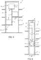
- Figure 5 illustrates a second embodiment of an elevator system and a method for operating an elevator system.
- the elevator system of Figure 5 is very similar to the one explained in connection with Figures 1 - 4 . Therefore, in the following explanation the embodiment of Figure 5 is mainly explained by pointing out the differences between these embodiments.
- the elevator system 1' of Figure 5 is a multicar elevator system where a plurality of elevator cars 3 of the same type as in Figures 1-4 are operated simultaneously.
- Each elevator car 3 is releasably connected to a respective frame 6 and can be removed via a landing opening provided at a plurality of landings 7, in a similar way as has been explained in connection with Figures 1 - 4 .
- the rails along which the frames move by the drive units are not shown, though they may be similarly implemented as in the embodiment of Figures 1 - 4 .
- the embodiment of Figure 5 is provided with a second elevator shaft 2', which is parallel with drive shaft 2.
- these two elevator shafts are connected by two transfer stations 13'.
- the transfer stations 13' are provided with additional rails or other suitable devices in order to facilitate that each elevator car 3 with the corresponding frame 6 may be transferred horizontally between the two elevator shafts 2, 2'. This makes it possible to provide a circulating motion where elevator cars 3 move upwards with one of the shafts 3 and downwards with the other one of the shafts 2' while transporting passengers or cargo, as illustrated with arrows in Figure 5 .
- Figures 1 to 5 show a rucksack-type elevator having guide rails or stator beams at the same side of the car.
- the present invention is suitable also for elevators having guide rails or stator beams at different sides of the car, such as at opposite sides of the car.
- Such an embodiment is illustrated in Figure 6 .
- the embodiment of Figure 6 is very similar to the one explained previously in connection with Figures 1 to 4 . Therefore, in the following the embodiment of Figure 6 is illustrated mainly by pointing out the differences between these embodiments.
- the elevator car 3" moves in an elevator shaft 2 where the rails 5 are arranged to the side walls of the elevator shaft 2, on opposite sides of the elevator car 3".
- Gliding parts 15" which preferably glide along the rails 5 by means of wheels, are arranged on opposite sides of the elevator car 3".
- the drive unit 4" is stationary in the elevator shaft 2 and moves the elevator car 3" and a counterweight 16'" by means of a rope 17"'.
- Mechanical fasteners 11" for releasing the elevator car 3" may be located in connection with a frame 6" connecting the elevator car 3" roof to the rope 17", and at the side walls of the elevator car 3". Also the electrical connections 10" may be implemented via the roof or side walls, or via both the roof and side walls, as illustrated by example.
Abstract
The invention relates to a solution for operating an elevator system. In order to simplify maintenance work of an elevator car, a landing door assembly (9) separating an elevator shaft from a landing (7) is removed to reveal a large shaft opening (8). An elevator car (3) located in the elevator shaft at the landing (7) is released from a frame (6) which is provided with a drive unit (4) moving the frame (6) and the elevator car (3) in the elevator shaft. The released elevator car (3) is moved out of the elevator shaft to the landing (7) via the large shaft opening (8).
Description
- This invention relates to an elevator system and more precisely to service and maintenance of an elevator system. In the following the invention will be mainly described by referring to a multicar elevator system. However, it needs to be observed, that this is only by way of example, and that the present invention in praxis can be implemented also in connection with other types of elevator systems.
- A previously known solution to facilitate maintenance work for an elevator car is to drive the elevator car to a dedicated service area in the elevator shaft. This location has been prepared to make it possible to access the devices that need maintenance.
- A drawback with the above-mentioned solution is that reserving a dedicated space in the elevator shaft for maintenance work requires additional space from the building, which is not easy to realize in a cost-efficient way.
- An alternative solution is to carry out maintenance work by providing the maintenance personnel with a route via which they can access the roof of the elevator car. In this way service personal standing on top of the elevator can carry out maintenance work. A drawback with such a solution is, however, that with this solution it is difficult to access all parts that need maintenance.
- An object of the present invention is to solve the above-mentioned problems. This object is achieved with an elevator system according to
independent claim 1 and a method according toindependent claim 12. - A large shaft opening at a landing in the elevator shaft makes it possible to release and remove the elevator car to the landing for maintenance work without a need to reserve any additional dedicated space from the building for maintenance purpose.
- Preferred embodiments of the invention are disclosed in the dependent claims.
- In the following the present invention will be described in closer detail by way of example and with reference to the attached drawings, in which
-
Figures 1 to 4 illustrate a first embodiment of an elevator system and a method for operating an elevator system, -
Figure 5 illustrates a second embodiment of an elevator system and a method for operating an elevator system, and -
Figure 6 illustrates a third embodiment of an elevator system and a method for operating an elevator system. -
Figures 1 to 4 illustrate a first embodiment of an elevator system and a method for operating anelevator system 1.Figure 1 illustrates a front view of a cross-section of anelevator shaft 2,Figure 2 is a top view of an elevator car along line II - II inFigure 1, Figure 3 is a side view of an elevator car along line III - III inFigure 2, and Figure 4 is a similar side view of an elevator car as inFigure 3 , but with the elevator car removed from the elevator shaft. - In the illustrated example, a
frame 6 with adrive unit 4 is provided to theelevator shaft 2. Theelevator car 3 is connected to theframe 6, such that thedrive unit 4 of the frame moves theelevator car 3 in the elevator shaft. - The
frame 6 is engaged to arail 5 attached to a wall in the elevator shaft such that interaction between therail 5 and thedrive unit 4 moves the frame with the elevator car in the shaft. By way of example, tworails 5 are illustrated inFigure 1 though the number of rails may vary depending on the implementation. - The drive unit may include a propulsion motor a power converter and a battery, for instance, in other words all devices needed to move the elevator car in the elevator shaft. Alternatively, the power converter and the battery may be provided stationary in the shaft. The propulsion motor may be a linear motor having a mover co-acting with a stator beam at the
rail 5, for instance. At least one of the stator beam and the mover may be provided with windings. Alternatively, in other implementations the drive unit may be provided with drive wheels engaging the rail by friction or teeth, for instance, to provide the interaction for moving the frame and elevator car in the elevator shaft. - In order to facilitate efficient maintenance of the elevator car, the connection between the
elevator car 3 and theframe 6 may be released such that the elevator car can be removed from the elevator shaft to alanding 7 at a floor in a building, which also is used to load or unload passengers or cargo to/from theelevator car 3 via theelevator car door 14 and thelanding door 9. Tough in some implementations it may be sufficient that such removal can be done at one specific landing only, it may be advantageous to provide theelevator system 1 with as many landings as possible which facilitate removal of the elevator car. In that way, in case a malfunction occurs in the elevator car due to which it remains stuck in the elevator shaft, the distance that the elevator car needs to be moved in theelevator shaft 2 before it can be removed to a landing is minimized. In the example ofFigures 1 to 4 it is assumed that the elevator shaft has threelandings 7 at which the elevator car can be removed. - A
landing 7 where theelevator car 3 can be removed is provided with a large shaft opening 8. Such a large shaft opening 8 has larger dimensions than theelevator car 3 to allow removal of the elevator car via this large shaft opening 8. An advantageous solution is to dimension the large shaft opening 8 to have a width W corresponding to the width of theelevator shaft 2, as illustrated inFigure 1 , and to have a height H corresponding to the height of the landing 7 (distance from floor to roof at the floor in the building where the landing is located), as illustrated inFigure 3 . In praxis, with such a dimensioning no intermediate wall exists between the interior of theelevator shaft 2 and the space where thelanding 7 is located. This is also advantageous, as it facilitates saving of concrete, for instance, which would be needed to build such an intermediate wall. Consequently, the elevator car in the elevator shaft is enclosed by elevator shaft walls from three sides, while thelarge opening 8 is located at the position where no elevator shaft wall is provided, as illustrated inFigure 2 . - In the illustrated example it is assumed that the
landing door assembly 9, which during use of the elevator system is attached to cover the shaft opening 8 as shown inFigures 2 and 3 , is removed and moved away to an other location when theelevator car 3 is removed. This is illustrated inFigure 4 , where thelanding door assembly 9, which may include one or more door panels, side panels, a top panel and a lower frame part, for instance, is arranged to rest against a back wall at thelanding 7. Preferably, thedoor assembly 9 is designed for quick removal to simplify maintenance work. Landing door assembly may contain a landing door safety contact, which may be connected to elevator safety chain by using an easily detachable socket or sockets. Therefore, the safety contact is operable to indicate to the elevator safety chain whether the removable landing door assembly is installed in its place or not. When the removable landing door assembly is not installed, safety chain remains open, preventing elevator service. The landing door assembly may comprise also other detachable electrical circuits, such as a call input circuit. - At this stage the
elevator car 3 is released from theframe 6. This may be done my looseningmechanical fasteners 11, such as bolts, andelectrical connections 10 from an inside of theelevator car 3, as illustrated inFigure 3 . Theelectrical connections 10 which ensure electric connection between theelevator system 1 and the control panel, elevator safety chain, signaling lights and the light sources in theelevator car 3, for instance, are preferably provided by using an easily detachable socket or sockets. -
Figure 4 illustrates the situation with theelevator car 3 already removed and supported by thelanding 7. To simplify the removal, the landing or elevator car may be provided with asuitable support device 12. In the illustrated example it is assumed that thesupport device 12 includes rails along which the elevator car may slide on the landing. These rails may be temporary, which means that they can be removed from thelanding 7 when not needed. In some implementations the rails may extend into the elevator shaft during removal, to support the elevator in the elevator shaft before it is released from the frame. Alternatively or in addition, it is possible that rolls or wheels are used as the support device. After maintenance is completed, elevator car may be returned to theframe 6 by using thesame support device 12. - As illustrated in
Figure 4 , once the elevator car is removed, theframe 6 is revealed. In this example the frame is a generally L shaped part made of steel for instance. This makes it possible for maintenance personnel to access all sides of theelevator car 3 via the landing, and also thedrive unit 4 and all other parts of the frame and rail, as well as other parts in immediate vicinity in the elevator shaft, via the lower part of the frame, for instance. Naturally, it is possible to use a frame which is differently shaped than theframe 6 illustrated by way of example. One possibility is to use a sling, which may surround the elevator car, for instance. Also the location where the connection between the frame and the elevator car is provided may vary. In some implementations the frame can be mainly located above the elevator car, and the connection between the frame and the elevator car is implemented via the roof of the elevator car as illustrated inFigure 6 , for instance. -
Figure 5 illustrates a second embodiment of an elevator system and a method for operating an elevator system. The elevator system ofFigure 5 is very similar to the one explained in connection withFigures 1 - 4 . Therefore, in the following explanation the embodiment ofFigure 5 is mainly explained by pointing out the differences between these embodiments. - The elevator system 1' of
Figure 5 is a multicar elevator system where a plurality ofelevator cars 3 of the same type as inFigures 1-4 are operated simultaneously. Eachelevator car 3 is releasably connected to arespective frame 6 and can be removed via a landing opening provided at a plurality oflandings 7, in a similar way as has been explained in connection withFigures 1 - 4 . For simplicity, the rails along which the frames move by the drive units are not shown, though they may be similarly implemented as in the embodiment ofFigures 1 - 4 . - In addition to the
elevator shaft 2, illustrated inFigures 1 - 4 , the embodiment ofFigure 5 is provided with a second elevator shaft 2', which is parallel withdrive shaft 2. In the upper and lower part of theelevator shafts 2, 2', these two elevator shafts are connected by two transfer stations 13'. - The transfer stations 13' are provided with additional rails or other suitable devices in order to facilitate that each
elevator car 3 with thecorresponding frame 6 may be transferred horizontally between the twoelevator shafts 2, 2'. This makes it possible to provide a circulating motion whereelevator cars 3 move upwards with one of theshafts 3 and downwards with the other one of the shafts 2' while transporting passengers or cargo, as illustrated with arrows inFigure 5 . - In such a multicar elevator system 1' it is advantageous to have the possibility of removing an
elevator car 3 to anearby landing 7 as has previously been explained, because this simplifies and speeds up maintenance work of asingle elevator car 3, and also makes it possible to minimize the time that the entire elevator system 1' is out of use due to such maintenance work. -
Figures 1 to 5 show a rucksack-type elevator having guide rails or stator beams at the same side of the car. However, the present invention is suitable also for elevators having guide rails or stator beams at different sides of the car, such as at opposite sides of the car. Such an embodiment is illustrated inFigure 6 . The embodiment ofFigure 6 is very similar to the one explained previously in connection withFigures 1 to 4 . Therefore, in the following the embodiment ofFigure 6 is illustrated mainly by pointing out the differences between these embodiments. - In the
elevator system 1" ofFigure 6 , theelevator car 3" moves in anelevator shaft 2 where therails 5 are arranged to the side walls of theelevator shaft 2, on opposite sides of theelevator car 3".Gliding parts 15" which preferably glide along therails 5 by means of wheels, are arranged on opposite sides of theelevator car 3". Thedrive unit 4" is stationary in theelevator shaft 2 and moves theelevator car 3" and a counterweight 16'" by means of a rope 17"'. -
Mechanical fasteners 11" for releasing theelevator car 3" may be located in connection with aframe 6" connecting theelevator car 3" roof to the rope 17", and at the side walls of theelevator car 3". Also theelectrical connections 10" may be implemented via the roof or side walls, or via both the roof and side walls, as illustrated by example. - It is to be understood that the above description and the accompanying figures are only intended to illustrate the present invention. It will be obvious to a person skilled in the art that the invention can be varied and modified without departing from the scope of the invention.
Claims (16)
- An elevator system (1, 1', 1") comprising:an elevator car (3, 3"),a drive unit (4, 4") moving the elevator car (3, 3") in an elevator shaft (2, 2') between landings at different levels, characterized in thatthe elevator system (1, 1', 1") comprises a landing (7) provided with a large shaft opening (8) into the elevator shaft (2, 2',) with larger dimensions than the elevator car (3, 3") to allow removal of the elevator car (3, 3") via said large shaft opening to the landing (7).
- The elevator system according to claim 1, wherein
each landing (7) is provided with a large shaft opening (8) into the elevator shaft (2, 2') with larger dimensions than the elevator car (3, 3") to allow removal of the elevator car via said large shaft opening (8). - The elevator system according to claim 1 or 2, wherein the large shaft opening (8) is provided with a removable landing door assembly (9) covering the large shaft opening (8) during operation of the elevator system (1, 1', 1").
- The elevator system according to one of claims 1 to 3, wherein the large shaft opening (8) has a width (W) corresponding to the width of the elevator shaft (2, 2') and a height (H) corresponding to the height of the landing (7).
- The elevator system according to one of claims 1 to 4, wherein the landing (7) or elevator car (3, 3") is provided with a support device (12) carrying the elevator car (3, 3") removed via the large shaft opening (8) to the landing (7).
- The elevator system according to one of claims 1 to 5, wherein
the elevator system comprises a frame (6) provided in the elevator shaft (2, 2'),
the drive unit (4) is provided to the frame (6), and
the elevator car (3, 3') is releasably connected to the frame (6) to move with the frame (6) in the elevator shaft (2, 2'). - The elevator system according to one of claims 1 to5, wherein
the elevator system comprises a frame (6, 6") releasably connected to the elevator car (3, 3")
the drive unit moves the elevator car (3, 3") in the shaft via the frame (6, 6"), and
the connection (10, 11; 10", 11") between the elevator car (3, 3") and the frame (6, 6") is releasable from an inside of the elevator car (3, 3"). - The elevator system according to one of claims 6, wherein
the elevator shaft (2, 2') is provided with a rail (5) along a wall of the elevator shaft, and
the drive unit (4) is connected to the rail (5) to move the frame (6) with the elevator car (3) in the elevator shaft (2, 2') along the rail by a force provided by interaction between the drive unit (4) and the rail (5). - The elevator system according to one of claims 1 to 8, wherein the elevator system (1') is a multicar system wherein a plurality of elevator cars (3) are simultaneously operated in the same elevator shaft.
- The elevator system according to one of claims 1 to 9, wherein the elevator system (1') comprises a second elevator shaft (2') and at least two transfer stations (13') transferring elevator cars (3) of the system between the elevator shafts (2, 2') to provide a circulating motion where elevator cars (3) move upwards with one of the shafts (2) and downwards with the other one of the shafts (2').
- The elevator system according to any of the preceding claims, wherein the removable landing door assembly comprises a landing door safety contact provided with a detachable socket, to connect the safety contact to an elevator safety chain.
- A method for operating an elevator system, characterized in that the method comprises:removing a landing door assembly (9) separating an elevator shaft (2, 2') from a landing (7) to reveal a large shaft opening (8),releasing an elevator car (3, 3") located in the elevator shaft (2, 2') at the landing (7) from a frame (6, 6") which is moved with a drive unit (4, 4") in the elevator shaft (2, 2'), andmoving the released elevator car (3, 3") out of the elevator shaft (2, 2') to the landing (7) via the large shaft opening (8).
- The method according to claim 12, wherein the moving of the released elevator car (3, 3") is carried out by using a support device (12) carrying the elevator car (3, 3") on the landing (7).
- The method according to claim 12 or 13, wherein the moving of the release elevator car (3, 3") is carried out by using a support device (12) including rails.
- The method according to one of claims 12 to 13, wherein releasing of the elevator car (3, 3") from the frame (6, 6") is carried out from an inside of the elevator car (3, 3").
- The method according to one of claims 12 to 15, wherein said releasing comprises releasing mechanical fasteners (11) and electrical connections (10).
Priority Applications (2)
| Application Number | Priority Date | Filing Date | Title |
|---|---|---|---|
| EP20198924.1A EP3974368A1 (en) | 2020-09-29 | 2020-09-29 | Elevator system and a method for operating an elevator system |
| CN202110972751.XA CN114314229A (en) | 2020-09-29 | 2021-08-24 | Elevator system and method for operating an elevator system |
Applications Claiming Priority (1)
| Application Number | Priority Date | Filing Date | Title |
|---|---|---|---|
| EP20198924.1A EP3974368A1 (en) | 2020-09-29 | 2020-09-29 | Elevator system and a method for operating an elevator system |
Publications (1)
| Publication Number | Publication Date |
|---|---|
| EP3974368A1 true EP3974368A1 (en) | 2022-03-30 |
Family
ID=72670547
Family Applications (1)
| Application Number | Title | Priority Date | Filing Date |
|---|---|---|---|
| EP20198924.1A Pending EP3974368A1 (en) | 2020-09-29 | 2020-09-29 | Elevator system and a method for operating an elevator system |
Country Status (2)
| Country | Link |
|---|---|
| EP (1) | EP3974368A1 (en) |
| CN (1) | CN114314229A (en) |
Citations (4)
| Publication number | Priority date | Publication date | Assignee | Title |
|---|---|---|---|---|
| EP0842888A1 (en) * | 1996-11-14 | 1998-05-20 | Otis Elevator Company | Horizontal and vertical passenger transport |
| WO2017058954A1 (en) * | 2015-09-28 | 2017-04-06 | Smart Lifts, Llc | Vertically and horizontally mobile elevator cabins |
| WO2019115269A1 (en) * | 2017-12-12 | 2019-06-20 | Thyssenkrupp Elevator Ag | Traveling unit for an elevator system |
| JP2019167214A (en) * | 2018-03-23 | 2019-10-03 | 積水化学工業株式会社 | Modification method of elevator |
-
2020
- 2020-09-29 EP EP20198924.1A patent/EP3974368A1/en active Pending
-
2021
- 2021-08-24 CN CN202110972751.XA patent/CN114314229A/en active Pending
Patent Citations (4)
| Publication number | Priority date | Publication date | Assignee | Title |
|---|---|---|---|---|
| EP0842888A1 (en) * | 1996-11-14 | 1998-05-20 | Otis Elevator Company | Horizontal and vertical passenger transport |
| WO2017058954A1 (en) * | 2015-09-28 | 2017-04-06 | Smart Lifts, Llc | Vertically and horizontally mobile elevator cabins |
| WO2019115269A1 (en) * | 2017-12-12 | 2019-06-20 | Thyssenkrupp Elevator Ag | Traveling unit for an elevator system |
| JP2019167214A (en) * | 2018-03-23 | 2019-10-03 | 積水化学工業株式会社 | Modification method of elevator |
Also Published As
| Publication number | Publication date |
|---|---|
| CN114314229A (en) | 2022-04-12 |
Similar Documents
| Publication | Publication Date | Title |
|---|---|---|
| US10118799B2 (en) | Multicar self-propelled elevator system | |
| EP3372547B1 (en) | Electric linear motor | |
| CN1187254C (en) | Small machine shop elevator | |
| EP0631968B1 (en) | Traction sheave elevator with drive machine below | |
| CN107000991B (en) | Device and method for independently moving at least two elevator cars in at least one shaft | |
| US20180029832A1 (en) | Vehicle and method for elevator system installation | |
| KR20110053468A (en) | Carrying device for relocating a car of an elevator | |
| EP3194319B1 (en) | Elevator car with removable battery | |
| CN108137281B (en) | Transportation system and method for ropeless elevator hoistway | |
| CN112955397A (en) | Elevator installation and method for operating an elevator installation with an auxiliary device | |
| US9415974B2 (en) | Method and arrangement for moving a heavy load | |
| EP3124419A1 (en) | Elevator recovery car | |
| US20210061612A1 (en) | Elevator system | |
| US5816368A (en) | Elevator cars switch hoistways while traveling vertically | |
| EP3974368A1 (en) | Elevator system and a method for operating an elevator system | |
| JP2017007778A (en) | Elevator system | |
| CN112888647A (en) | Elevator system with a first part of an elevator system and a second part of an elevator system | |
| EP3216735A1 (en) | Pulsed opening of elevator brake enabling passenger evacuation | |
| JPH05124781A (en) | Elevator | |
| CN114096480A (en) | Method and elevator arrangement | |
| CN115465737B (en) | Parallel double-car elevator system and control method | |
| WO2018042638A1 (en) | Elevator system | |
| EP1428784A2 (en) | Machineroomless elevator with belt and/or chain traction | |
| EP3892577A1 (en) | Elevator control cabinet and method for installation of an electrical apparatus into an elevator control cabinet | |
| EP3705442A1 (en) | An elevator car energy storage mounting arrangement and a maintenance method |
Legal Events
| Date | Code | Title | Description |
|---|---|---|---|
| PUAI | Public reference made under article 153(3) epc to a published international application that has entered the european phase |
Free format text: ORIGINAL CODE: 0009012 |
|
| STAA | Information on the status of an ep patent application or granted ep patent |
Free format text: STATUS: REQUEST FOR EXAMINATION WAS MADE |
|
| 17P | Request for examination filed |
Effective date: 20210708 |
|
| AK | Designated contracting states |
Kind code of ref document: A1 Designated state(s): AL AT BE BG CH CY CZ DE DK EE ES FI FR GB GR HR HU IE IS IT LI LT LU LV MC MK MT NL NO PL PT RO RS SE SI SK SM TR |
|
| STAA | Information on the status of an ep patent application or granted ep patent |
Free format text: STATUS: EXAMINATION IS IN PROGRESS |
|
| 17Q | First examination report despatched |
Effective date: 20220930 |
|
| P01 | Opt-out of the competence of the unified patent court (upc) registered |
Effective date: 20230525 |