EP3974322B1 - Boom-pod mit berührungssensitivem bildschirm - Google Patents
Boom-pod mit berührungssensitivem bildschirm Download PDFInfo
- Publication number
- EP3974322B1 EP3974322B1 EP21198913.2A EP21198913A EP3974322B1 EP 3974322 B1 EP3974322 B1 EP 3974322B1 EP 21198913 A EP21198913 A EP 21198913A EP 3974322 B1 EP3974322 B1 EP 3974322B1
- Authority
- EP
- European Patent Office
- Prior art keywords
- data
- processor
- boom
- further configured
- flight refueling
- Prior art date
- Legal status (The legal status is an assumption and is not a legal conclusion. Google has not performed a legal analysis and makes no representation as to the accuracy of the status listed.)
- Active
Links
Images




Classifications
-
- G—PHYSICS
- G06—COMPUTING OR CALCULATING; COUNTING
- G06F—ELECTRIC DIGITAL DATA PROCESSING
- G06F3/00—Input arrangements for transferring data to be processed into a form capable of being handled by the computer; Output arrangements for transferring data from processing unit to output unit, e.g. interface arrangements
- G06F3/14—Digital output to display device ; Cooperation and interconnection of the display device with other functional units
- G06F3/1423—Digital output to display device ; Cooperation and interconnection of the display device with other functional units controlling a plurality of local displays, e.g. CRT and flat panel display
-
- B—PERFORMING OPERATIONS; TRANSPORTING
- B64—AIRCRAFT; AVIATION; COSMONAUTICS
- B64D—EQUIPMENT FOR FITTING IN OR TO AIRCRAFT; FLIGHT SUITS; PARACHUTES; ARRANGEMENT OR MOUNTING OF POWER PLANTS OR PROPULSION TRANSMISSIONS IN AIRCRAFT
- B64D39/00—Refuelling during flight
-
- B—PERFORMING OPERATIONS; TRANSPORTING
- B64—AIRCRAFT; AVIATION; COSMONAUTICS
- B64D—EQUIPMENT FOR FITTING IN OR TO AIRCRAFT; FLIGHT SUITS; PARACHUTES; ARRANGEMENT OR MOUNTING OF POWER PLANTS OR PROPULSION TRANSMISSIONS IN AIRCRAFT
- B64D39/00—Refuelling during flight
- B64D39/02—Means for paying-in or out hose
-
- B—PERFORMING OPERATIONS; TRANSPORTING
- B64—AIRCRAFT; AVIATION; COSMONAUTICS
- B64U—UNMANNED AERIAL VEHICLES [UAV]; EQUIPMENT THEREFOR
- B64U20/00—Constructional aspects of UAVs
- B64U20/80—Arrangement of on-board electronics, e.g. avionics systems or wiring
- B64U20/87—Mounting of imaging devices, e.g. mounting of gimbals
-
- G—PHYSICS
- G06—COMPUTING OR CALCULATING; COUNTING
- G06F—ELECTRIC DIGITAL DATA PROCESSING
- G06F3/00—Input arrangements for transferring data to be processed into a form capable of being handled by the computer; Output arrangements for transferring data from processing unit to output unit, e.g. interface arrangements
- G06F3/01—Input arrangements or combined input and output arrangements for interaction between user and computer
- G06F3/03—Arrangements for converting the position or the displacement of a member into a coded form
- G06F3/041—Digitisers, e.g. for touch screens or touch pads, characterised by the transducing means
-
- G—PHYSICS
- G06—COMPUTING OR CALCULATING; COUNTING
- G06F—ELECTRIC DIGITAL DATA PROCESSING
- G06F3/00—Input arrangements for transferring data to be processed into a form capable of being handled by the computer; Output arrangements for transferring data from processing unit to output unit, e.g. interface arrangements
- G06F3/01—Input arrangements or combined input and output arrangements for interaction between user and computer
- G06F3/048—Interaction techniques based on graphical user interfaces [GUI]
- G06F3/0484—Interaction techniques based on graphical user interfaces [GUI] for the control of specific functions or operations, e.g. selecting or manipulating an object, an image or a displayed text element, setting a parameter value or selecting a range
- G06F3/04845—Interaction techniques based on graphical user interfaces [GUI] for the control of specific functions or operations, e.g. selecting or manipulating an object, an image or a displayed text element, setting a parameter value or selecting a range for image manipulation, e.g. dragging, rotation, expansion or change of colour
-
- G—PHYSICS
- G06—COMPUTING OR CALCULATING; COUNTING
- G06T—IMAGE DATA PROCESSING OR GENERATION, IN GENERAL
- G06T11/00—Two-dimensional [2D] image generation
-
- G—PHYSICS
- G06—COMPUTING OR CALCULATING; COUNTING
- G06T—IMAGE DATA PROCESSING OR GENERATION, IN GENERAL
- G06T3/00—Geometric image transformations in the plane of the image
- G06T3/60—Rotation of whole images or parts thereof
-
- G—PHYSICS
- G06—COMPUTING OR CALCULATING; COUNTING
- G06T—IMAGE DATA PROCESSING OR GENERATION, IN GENERAL
- G06T7/00—Image analysis
- G06T7/70—Determining position or orientation of objects or cameras
-
- B—PERFORMING OPERATIONS; TRANSPORTING
- B64—AIRCRAFT; AVIATION; COSMONAUTICS
- B64D—EQUIPMENT FOR FITTING IN OR TO AIRCRAFT; FLIGHT SUITS; PARACHUTES; ARRANGEMENT OR MOUNTING OF POWER PLANTS OR PROPULSION TRANSMISSIONS IN AIRCRAFT
- B64D47/00—Equipment not otherwise provided for
- B64D47/08—Arrangements of cameras
-
- G—PHYSICS
- G06—COMPUTING OR CALCULATING; COUNTING
- G06T—IMAGE DATA PROCESSING OR GENERATION, IN GENERAL
- G06T2207/00—Indexing scheme for image analysis or image enhancement
- G06T2207/10—Image acquisition modality
- G06T2207/10016—Video; Image sequence
-
- G—PHYSICS
- G06—COMPUTING OR CALCULATING; COUNTING
- G06T—IMAGE DATA PROCESSING OR GENERATION, IN GENERAL
- G06T2207/00—Indexing scheme for image analysis or image enhancement
- G06T2207/20—Special algorithmic details
- G06T2207/20081—Training; Learning
-
- G—PHYSICS
- G06—COMPUTING OR CALCULATING; COUNTING
- G06T—IMAGE DATA PROCESSING OR GENERATION, IN GENERAL
- G06T2207/00—Indexing scheme for image analysis or image enhancement
- G06T2207/20—Special algorithmic details
- G06T2207/20084—Artificial neural networks [ANN]
Definitions
- Boom pods used to control in-flight refueling operations currently include banks of gauges, knobs, and switches that individually control aspects of the refueling boom. Such boom pods offer insufficient flexibility and situational awareness to the operator. Furthermore, many of the physical knobs and switches are not needed during any given operational phase, but continue to clutter the control surface ad may contribute to user error.
- US 9 150 310 B1 describes methods and systems for directing remote aerial refueling operations.
- EP 2 300 321 A2 describes a system and method for displaying aerial refueling symbology.
- WO 2009/082400 A1 describes an aircraft command and control system.
- embodiments of the inventive concepts disclosed herein are directed to a boom pod with an adaptable user interface that automatically reconfigures based on operation phase. Elements of the user interface may also be manually reconfigured based on operator preference. Operator reconfigurations may be recorded for use during similar phases in subsequent operations.
- a controller automatically records system status during a refueling operation and prepares a digital log entry.
- portions of the use interface are dedicated to augmented displays to assist the operator at any given operational phase.
- inventive concepts are not limited in their application to the details of construction and the arrangement of the components or steps or methodologies set forth in the following description or illustrated in the drawings.
- inventive concepts disclosed herein may be practiced without these specific details.
- well-known features may not be described in detail to avoid unnecessarily complicating the instant disclosure.
- inventive concepts disclosed herein are capable of other embodiments or of being practiced or carried out in various ways. Also, it is to be understood that the phraseology and terminology employed herein is for the purpose of description and should not be regarded as limiting.
- a letter following a reference numeral is intended to reference an embodiment of the feature or element that may be similar, but not necessarily identical, to a previously described element or feature bearing the same reference numeral (e.g., 1, 1a, 1b).
- reference numeral e.g. 1, 1a, 1b
- Such shorthand notations are used for purposes of convenience only, and should not be construed to limit the inventive concepts disclosed herein in any way unless expressly stated to the contrary.
- any reference to "one embodiment,” or “some embodiments” means that a particular element, feature, structure, or characteristic described in connection with the embodiment is included in at least one embodiment of the inventive concepts disclosed herein.
- the appearances of the phrase “in some embodiments” in various places in the specification are not necessarily all referring to the same embodiment, and embodiments of the inventive concepts disclosed may include one or more of the features expressly described or inherently present herein, or any combination of sub-combination of two or more such features, along with any other features which may not necessarily be expressly described or inherently present in the instant disclosure.
- embodiments of the inventive concepts disclosed herein are directed to a boom pod with an adaptable user interface that automatically reconfigures based on operation phase. Elements of the user interface may also be manually reconfigured based on operator preference. Operator reconfigurations may be recorded for use during similar phases in subsequent operations.
- a controller automatically records system status during a refueling operation and prepares a digital log entry. Portions of the use interface are dedicated to augmented displays to assist the operator at any given operational phase.
- FIG. 1 a block diagram of a system according to an exemplary embodiment is shown.
- the system embodied in an aircraft refueling boom pod, includes a processor 100, memory 102 in data communication with the processor 100 for embodying processor executable code, and one or more displays 104.
- the displays 104 may be touch sensitive to allow for input and interaction with the functionality of the processor 100.
- one or more cameras 106 are in data communication with the processor 100 to provide a real-time image or data derived from a real-time image to the displays 104.
- a data storage element 108 in data commination with the processor 100 may store a record of refueling interactions in a log for later contemporaneous or subsequent transmission via a data communication element 110. Furthermore, the data storage element 108 may record changes to a user interface via operator interaction with the touch sensitive displays 104 to maintain a persistent, desired layout for each operator during each phase of a refueling operation.
- the processor 100 may apply one or more augmented reality overlays to images from the cameras 106.
- a camera 106 at a relatively fixed location corresponding to a refueling boom arm may produce an image to assist in positioning the boom arm; the processor 100 may apply an augmented reality overlay to the image that corresponds to the maximum movement of the boom arm.
- the processor 100 may apply image processing algorithms such as edge detection to apply an augmented reality overlay of the aircraft being refueled to enhance the operator's view of the aircraft, possibly including low-light enhancement.
- the processor 100 may determine an aircraft type based on a database of known aircraft from the data storage element 108, and apply an augmented reality overlay to enhance important features of the aircraft.
- the processor 100 may utilize image processing algorithms or other onboard sensors to determine the location of the boom arm with respect to the images from the cameras 104; in such embodiments, the processor 100 may render an enhanced view of the boom arm and / or an indication of a calculated distance and direction between the boom arm and the corresponding refueling port on the aircraft.
- the processor 100 may use an image from one or more of the cameras 104 to determine certain image overlays such as the boundaries of the boom arm and / or a current location of the boom, but render those overlays on a blank portion of the display without the image.
- FIG. 2 a perspective view of a boom pod 200 according to an exemplary embodiment is shown.
- the boom pod 200 may be divided into an informational panel 202 and a control panel 206; in at least one embodiment, the control panel 206 may be substantially similar to existing control panels 206.
- boom pods 200 may have included an ancillary control panel 204; but in at least one embodiment, the ancillary control panel 204 is not needed.
- existing controls may be obviated and removed.
- the informational panel 202 comprises one or more displays 208, 210 in place of existing gauges, indicator lights, control knobs, and switches of existing boom pods 200.
- the displays 208, 210 maybe stacked vertically or arranged horizontally.
- One or more of the displays 208, 210 may include a touch sensitive screen for selecting inputs that generally correspond to the functionality of the existing switches and knobs. Alternatively, such inputs may correspond to sets of functions that previously required multiple switch and / or knob inputs.
- one or more of the displays 208, 210, or some portion thereof may include a relatively fixed layout while other displays 208, 210 or portions of displays 208, 210 may be reconfigurable via touch inputs.
- layouts may be operator specific or operational phase specific such that layouts may be automatically reconfigured to present inputs in an ergonomically efficient way at each operational phase.
- the user interface 300 may be divided into a layout display control element 302 and one or more informational display elements 304, 306.
- the layout display control element 302 may comprise a control group for selecting layouts to render in the one or more informational display elements 304, 306.
- Each layout may be associated with one of the informational display elements 304, 306 by default, and may be permanently or temporarily reconfigurable to another of the informational display elements 304, 306.
- one of the informational display elements 304, 306 may include comms controls. Furthermore, one of informational display elements 304, 306 may include a fuel widget or layout element 308 generally corresponding to fuel transfer metrics; likewise, a boom widget of layout element 310 may generally correspond to the disposition and orientation of the boom arm. Such fuel and boom layout elements 308, 310 may be generally associated with a singular layout element that may be selected by the operator; alternatively, or in addition, fuel and boom layout elements 308, 310 may be associated with an operational phase to automatically render during that operational phase and de-render outside of that operational phase to remove unneeded visual clutter and improve situational awareness.
- data elements that may be displayed in one or more of the available layouts may be bounded by safe operational ranges; the processor rendering the user interface 300 may determine when an undisplayed data point is outside of a bounded range and provide a indicator to the operator such as illuminating a corresponding control in the layout display control element 302 or automatically rendering the corresponding layout.
- the layout display control element 302 and one or more informational display elements 304, 306 may be repositionable by an operator such as via tap-and-hold.
- data corresponding to data being displayed, and / or actual recorded representations may be recorded in a log.
- data and representations of undisplayed data may be recorded in the log also.
- one or more of the layouts may include lighting controls.
- lighting controls may be persistent in one or more of the informational display elements 304, 306 and / or the layout display control element 302.
- Lighting controls may be associated with an operation phase such that light levels are set to predetermined levels at each operational phase, potentially based on a time of day and / or mission requirements. Increment and decrement controls may allow light levels to be set at certain predefined levels. Lighting controls may include light positioning where available.
- certain lights may be dedicated to giving the pilot of the fueling aircraft directional signals; those lights may be automated according to positioning algorithms, potentially utilizing one or more onboard cameras, with the option to allow an operator to give further instructions by manipulating a touch screen control that is translated to light indicators.
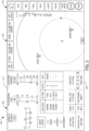
- a graphical user interface 400 according to an exemplary embodiment is shown.
- the user interface 400 may be rendered as a predefined layout including boom arm position data 408, boom arm controls 406 and indicators, and fuel transfer data 404.
- Such user interface 400 may be rendered in response to a specific refueling operation phase.
- a layout display control element 402 comprises a control group for selecting layouts to render in the user interface 400, including the boom arm position data 408.
- layout display control element 402 may be repositioned by an operator; furthermore, individual data display and control elements 408, 406, 404 may be repositioned within the larger layout. Such repositioning may be recorded along with an operational phase and an operator identify such that in subsequent refueling operations, the repositioned elements 408, 406, 404 will be rendered in those new positions.
- the user interface 500 may be divided into a layout display control element 502 and one or more informational display elements 504, 506.
- the layout display control element 502 may comprise a control group for selecting layouts to render in the one or more informational display elements 504, 506.
- Each layout may be associated with one of the informational display elements 504, 506 by default, and may be permanently or temporarily reconfigurable to another of the informational display elements 504, 506.
- a processor may automatically determine which layouts to render based on the operation phase of the refueling operation. Where an operator selects other than the automatically determine layout, the processor may record the altered layout paradigm for subsequent operations.
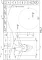
- the user interface 600 may be divided into a layout display control element 602 and one or more informational display elements 604, 606. At least one of the informational display elements 604, 606 may render a boom arm position graphic derived from one or more image streams from cameras on the refueling aircraft.
- the graphic may comprise one or more boom arm boundary indicators 608 defined by the maximum movement range of the boom arm as would be visible in the image stream.
- a boom arm position indicator 610 may also be rendered.
- the one or more boom arm boundary indicators 608 and boom arm position indicator 610 may be rendered with real-time positions in the informational display element 606 corresponding to where they would be displayed as an overlay to a streaming image, but the streaming image is not rendered.
- features of the refueling aircraft may be identified via reference to a database of aircraft, image processing algorithms such as edge detection, a trained neural network, etc., and called out in the rendered overlay.
- image processing algorithms such as edge detection, a trained neural network, etc.
- appropriate gauge limits may be identified and continuously or periodically monitored with corresponding indications whenever a gauge is outside such limits.
Landscapes
- Engineering & Computer Science (AREA)
- Theoretical Computer Science (AREA)
- Physics & Mathematics (AREA)
- General Physics & Mathematics (AREA)
- General Engineering & Computer Science (AREA)
- Aviation & Aerospace Engineering (AREA)
- Human Computer Interaction (AREA)
- Microelectronics & Electronic Packaging (AREA)
- Mechanical Engineering (AREA)
- Remote Sensing (AREA)
- Computer Vision & Pattern Recognition (AREA)
- User Interface Of Digital Computer (AREA)
Claims (14)
- Boom-Pod zur Luftbetankung, umfassend:eine Vielzahl von Anzeigen (104), von denen mindestens eine berührungsempfindlich ist;ein Datenspeicherelement undmindestens einen Prozessor (100) in Datenkommunikation mit der Vielzahl von Anzeigen, das Datenspeicherelement und einen Speicher, der prozessorausführbaren Code speichert, um den mindestens einen Prozessor (100) zu Folgendem zu konfigurieren:Bestimmen einer Betriebsphase einer Betankungsoperation;Bestimmen eines oder mehrerer Daten- und Steuerungslayouts, die der Betriebsphase entsprechen;Rendern des einen oder der mehreren Daten- und Steuerungslayouts auf der Vielzahl von Anzeigen während der Betriebsphase;und dadurch gekennzeichnet, dass es ferner dazu konfiguriert ist, eine Eingabe über die berührungsempfindliche Anzeige zu empfangen, die eine Neupositionierung eines Daten- und Steuerungslayouts angibt;Zuordnen des neu positionierten Daten- und Steuerungslayouts einer Bedieneridentität und der Betriebsphase; undAufzeichnen eines Standorts des neu positionierten Daten- und Steuerungslayouts und der zugeordneten Bedieneridentität und Betriebsphase in dem Datenspeicherelement.
- Boom-Pod zur Luftbetankung nach Anspruch 1, ferner umfassend eine oder mehrere Kameras in Datenkommunikation mit dem mindestens einen Prozessor, wobei der mindestens eine Prozessor (100) ferner zu Folgendem konfiguriert ist:Empfangen eines Bildstroms von der einen oder den mehreren Kameras;Bestimmen einer begrenzten Reichweite eines Boom-Arms innerhalb des Bildstroms;Bestimmen eines aktuellen Standorts des Boom-Arms innerhalb des Bildstroms; undRendern eines Boom-Positionslayouts auf der Vielzahl von Anzeigen, das die begrenzte Reichweite und den aktuellen Standort beinhaltet.
- Boom-Pod zur Luftbetankung nach Anspruch 2, wobei der mindestens eine Prozessor (100) ferner zu Folgendem konfiguriert ist:Rendern des Bildstroms; undÜberlagern des Boom-Positionslayouts über den Bildstrom.
- Boom-Pod zur Luftbetankung nach Anspruch 3, wobei der mindestens eine Prozessor (100) ferner dazu konfiguriert ist, eine Bildtransformationsoperation an dem Bildstrom durchzuführen, um das Bild entlang einer Achse zu spiegeln.
- Boom-Pod zur Luftbetankung nach einem der Ansprüche 1 bis 4, ferner umfassend ein Datenkommunikationselement in Datenkommunikation mit dem mindestens einen Prozessor, wobei der mindestens eine Prozessor ferner zu Folgendem konfiguriert ist:Aufzeichnen eines Protokolls von Datenpunkten, die den Daten- und Steuerungslayouts entsprechen, in dem Datenspeicherelement; undperiodisches Übertragen der aufgezeichneten Protokolle in einen zentralen Datenspeicher.
- Boom-Pod zur Luftbetankung nach Anspruch 5, wobei der mindestens eine Prozessor (100) ferner dazu konfiguriert ist, ein Protokoll von Datenpunkten, die nicht gerenderten Daten- und Steuerungslayouts entsprechen, in dem Datenspeicherelement aufzuzeichnen.
- Boom-Pod zur Luftbetankung nach einem der Ansprüche 1 bis 6, wobei der mindestens eine Prozessor (100) ferner zu Folgendem konfiguriert ist:Bestimmen, dass ein Datenpunkt, der nicht in einem beliebigen gerenderten Daten- und Steuerungslayout beinhaltet ist, außerhalb einer vorgegebenen Grenze liegt; undRendern einer Angabe, dass ein anderes Daten- und Steuerungslayout, das den Datenpunkt beinhaltet, gerendert werden soll.
- System zur Luftbetankung von Flugzeugen, umfassend einen Boom-Pod zur Luftbetankung nach Anspruch 1.
- System zur Luftbetankung von Flugzeugen nach Anspruch 8, ferner umfassend eine oder mehrere Kameras (106) in Datenkommunikation mit dem mindestens einen Prozessor, wobei der mindestens eine Prozessor (100) ferner zu Folgendem konfiguriert ist:Empfangen eines Bildstroms von der einen oder den mehreren Kameras;Bestimmen einer begrenzten Reichweite eines Boom-Arms innerhalb des Bildstroms;Bestimmen eines aktuellen Standorts des Boom-Arms innerhalb des Bildstroms; undRendern eines Boom-Positionslayouts auf der mindestens einen Anzeige, das die begrenzte Reichweite und den aktuellen Standort beinhaltet.
- System zur Luftbetankung von Flugzeugen nach Anspruch 9, wobei der mindestens eine Prozessor (100) ferner zu Folgendem konfiguriert ist:Rendern des Bildstroms; undÜberlagern des Boom-Positionslayouts über den Bildstrom.
- System zur Luftbetankung von Flugzeugen nach Anspruch 10, wobei der mindestens eine Prozessor ferner dazu konfiguriert ist, eine Bildtransformationsoperation an dem Bildstrom durchzuführen, um das Bild entlang einer Achse zu spiegeln.
- System zur Luftbetankung von Flugzeugen nach Anspruch 8 bis 11, ferner umfassend ein Datenspeicherelement und ein Datenkommunikationselement in Datenkommunikation mit dem mindestens einen Prozessor, wobei der mindestens eine Prozessor ferner zu Folgendem konfiguriert ist:Aufzeichnen eines Protokolls von Datenpunkten, die den Daten- und Steuerungslayouts entsprechen, in dem Datenspeicherelement; undperiodisches Übertragen der aufgezeichneten Protokolle in einen zentralen Datenspeicher.
- System zur Luftbetankung von Flugzeugen nach Anspruch 12, wobei der mindestens eine Prozessor (100) ferner dazu konfiguriert ist, ein Protokoll von Datenpunkten, die nicht gerenderten Daten- und Steuerungslayouts entsprechen, in dem Datenspeicherelement aufzuzeichnen.
- System zur Luftbetankung von Flugzeugen nach einem der Ansprüche 8 bis 13, wobei der mindestens eine Prozessor (100) ferner zu Folgendem konfiguriert ist:Bestimmen, dass ein Datenpunkt, der nicht in einem beliebigen gerenderten Daten- und Steuerungslayout beinhaltet ist, außerhalb einer vorgegebenen Grenze liegt; undRendern einer Angabe, dass ein anderes Daten- und Steuerungslayout, das den Datenpunkt beinhaltet, gerendert werden soll.
Applications Claiming Priority (1)
| Application Number | Priority Date | Filing Date | Title |
|---|---|---|---|
| US17/034,372 US11599323B2 (en) | 2020-09-28 | 2020-09-28 | Touchscreen boom pod |
Publications (2)
| Publication Number | Publication Date |
|---|---|
| EP3974322A1 EP3974322A1 (de) | 2022-03-30 |
| EP3974322B1 true EP3974322B1 (de) | 2025-03-19 |
Family
ID=77951568
Family Applications (1)
| Application Number | Title | Priority Date | Filing Date |
|---|---|---|---|
| EP21198913.2A Active EP3974322B1 (de) | 2020-09-28 | 2021-09-24 | Boom-pod mit berührungssensitivem bildschirm |
Country Status (2)
| Country | Link |
|---|---|
| US (1) | US11599323B2 (de) |
| EP (1) | EP3974322B1 (de) |
Families Citing this family (5)
| Publication number | Priority date | Publication date | Assignee | Title |
|---|---|---|---|---|
| US12077314B1 (en) | 2021-04-08 | 2024-09-03 | Onstation Corporation | Transforming aircraft using low-cost attritable aircraft modified with adaptive suites |
| US12077313B1 (en) | 2021-05-28 | 2024-09-03 | Onstation Corporation | Low-cost attritable aircraft modified with adaptive suites |
| USD1126224S1 (en) * | 2022-09-14 | 2026-05-12 | Boston Scientific Scimed, Inc. | Display panel for a co-registration imaging system with graphical user interface |
| USD1109764S1 (en) * | 2022-09-14 | 2026-01-20 | Boston Scientific Scimed, Inc. | Display panel for a co-registration imaging system with graphical user interface |
| USD1113948S1 (en) * | 2024-03-15 | 2026-02-17 | Gestalt Diagnostics, LLC | Display screen or portion thereof with an animated graphical user interface |
Citations (1)
| Publication number | Priority date | Publication date | Assignee | Title |
|---|---|---|---|---|
| EP2300321B1 (de) * | 2008-06-13 | 2015-05-20 | The Boeing Company | System und verfahren zur symbologieanzeige für auftanken während des fluges |
Family Cites Families (55)
| Publication number | Priority date | Publication date | Assignee | Title |
|---|---|---|---|---|
| US4025193A (en) | 1974-02-11 | 1977-05-24 | The Boeing Company | Apparatus suitable for use in orienting aircraft in-flight for refueling or other purposes |
| US4298176A (en) | 1979-03-01 | 1981-11-03 | Mcdonnell Douglas Corporation | Remote refueling station |
| DE3440812C2 (de) | 1984-11-08 | 1987-04-30 | Messerschmitt-Bölkow-Blohm GmbH, 8012 Ottobrunn | Steuerstand für eine Betankungseinrichtung für Flugzeuge während des Fluges |
| US5530650A (en) | 1992-10-28 | 1996-06-25 | Mcdonnell Douglas Corp. | Computer imaging system and method for remote in-flight aircraft refueling |
| FR2705082B1 (fr) | 1993-05-12 | 1995-08-04 | Aerospatiale | Système de ravitaillement en vol. |
| US5904729A (en) | 1997-03-04 | 1999-05-18 | The Boeing Company | Automated director light system for aerial refueling operations |
| US6512527B1 (en) | 1999-09-08 | 2003-01-28 | Rockwell Collins, Inc. | Method and apparatus for interactively selecting display parameters for an avionices flight display |
| USD485279S1 (en) | 2002-10-28 | 2004-01-13 | Groxis, Inc. | Knowledge map user interface for a display |
| US7834819B2 (en) * | 2004-04-01 | 2010-11-16 | Polyvision Corporation | Virtual flip chart method and apparatus |
| US7309048B2 (en) * | 2005-07-29 | 2007-12-18 | The Boeing Company | Vision system and method incorporating graphics symbology for use in a tanker refueling system |
| US7298291B2 (en) | 2005-07-29 | 2007-11-20 | The Boeing Company | Graphical symbology apparatus for use in an airborne refueling system |
| USD549722S1 (en) | 2006-11-17 | 2007-08-28 | Hitachi Construction Machinery Co., Ltd. | Graphic user interface for display for construction machine |
| USD589526S1 (en) | 2007-01-29 | 2009-03-31 | Johnson Controls Technology Company | Graphical user interface for a display screen |
| JP2011507755A (ja) | 2007-12-21 | 2011-03-10 | ザ・ボーイング・カンパニー | 航空機のコマンド及び制御システム |
| USD614192S1 (en) | 2008-07-22 | 2010-04-20 | Hitachi High-Technologies Corporation | Graphical user interface for a computer display |
| US8370002B2 (en) | 2009-04-03 | 2013-02-05 | The Boeing Company | Multi-mission remote aerial refueling operator system |
| IT1394808B1 (it) | 2009-06-04 | 2012-07-13 | Galileo Avionica S P A Ora Selex Galileo Spa | Sistema di rifornimento assistito in volo |
| EP2336028A1 (de) | 2009-12-18 | 2011-06-22 | EADS Construcciones Aeronauticas, S.A. | Verfahren und System für verbesserte visuelle Überwachung der Luftbetankung |
| US9150310B1 (en) * | 2010-09-10 | 2015-10-06 | The Boeing Company | Methods and systems for directing remote aerial refueling operations |
| USD714339S1 (en) | 2010-12-03 | 2014-09-30 | Life Technologies Corporation | Display screen with graphical user interface of a cell counter |
| USD695303S1 (en) | 2011-12-22 | 2013-12-10 | Blackberry Limited | Display screen with a graphical user interface |
| USD753684S1 (en) | 2012-07-20 | 2016-04-12 | Siemens Aktiengesellschaft | Display screen with graphical user interface for a train operator control |
| USD742418S1 (en) | 2012-11-13 | 2015-11-03 | Wartsila Finland Oy | Propulsion control system for ship with a display |
| USD790558S1 (en) | 2013-05-30 | 2017-06-27 | P&W Solutions Co., Ltd. | Display screen for a personal digital assistant with graphical user interface |
| EP2808260B1 (de) | 2013-05-31 | 2018-04-25 | Airbus Defence and Space SA | Anzeigesystem für Luftbetankung und entsprechendes Verfahren |
| USD760237S1 (en) | 2013-12-05 | 2016-06-28 | Airwatch Llc | Display screen with a graphical user interface for a management console application |
| USD754680S1 (en) | 2013-12-05 | 2016-04-26 | Lg Electronics Inc. | Display of a television receiver with graphical user interface |
| USD750123S1 (en) | 2014-02-14 | 2016-02-23 | Aspen Technology, Inc. | Display screen with graphical user interface |
| USD785016S1 (en) | 2014-06-23 | 2017-04-25 | Deutsche Bank Ag | Display screen with graphical user interface |
| USD823312S1 (en) | 2014-08-11 | 2018-07-17 | Sony Corporation | Display panel or screen with graphical user interface |
| USD828845S1 (en) | 2015-01-05 | 2018-09-18 | Dolby International Ab | Display screen or portion thereof with transitional graphical user interface |
| USD778935S1 (en) | 2015-03-27 | 2017-02-14 | Kruss GmbH, Wissenschaftliche Laborgerate | Display screen with transitional graphical user interface |
| US11106329B2 (en) | 2015-09-18 | 2021-08-31 | Honeywell International Inc. | Flight deck display systems and methods for generating cockpit displays including dynamic taxi turnoff icons |
| USD784391S1 (en) | 2015-11-30 | 2017-04-18 | Mitsubishi Electric Corporation | Display screen with animated graphical user interface for converting machine |
| USD800739S1 (en) | 2016-02-16 | 2017-10-24 | General Electric Company | Display screen with graphical user interface for displaying test details of an engine control test |
| JP1622396S (ja) | 2016-04-19 | 2019-01-21 | 生体情報モニター機能付き電子計算機 | |
| USD826977S1 (en) | 2016-07-27 | 2018-08-28 | Beckman Coulter, Inc. | Display screen with graphical user interface for a laboratory instrument |
| US9997078B2 (en) | 2016-09-09 | 2018-06-12 | Garmin International, Inc. | Obstacle determination and display system |
| USD823869S1 (en) | 2016-10-14 | 2018-07-24 | Life Technologies Corporation | Blot and gel imaging instrument display screen with graphical user interface |
| CN106428583A (zh) | 2016-10-14 | 2017-02-22 | 北京蓝天多维科技有限公司 | 空中加油中的受油机末端引导与记录装置 |
| US10088998B2 (en) | 2017-01-26 | 2018-10-02 | Honeywell International Inc. | Methods and apparatus for dynamically updating drop zone data during flight |
| US10332294B2 (en) | 2017-08-16 | 2019-06-25 | The Boeing Company | Methods and systems for head up display (HUD) of aerial refueling operation status and signaling |
| US10761674B2 (en) | 2018-01-18 | 2020-09-01 | Honeywell International Inc. | Systems and methods for providing user-manipulated primary flight display (PFD) data onboard an aircraft |
| USD876448S1 (en) | 2018-07-06 | 2020-02-25 | Revotek Co., Ltd | Display screen with graphical user interface for bio-printer |
| TWD197848S (zh) | 2018-07-26 | 2019-06-01 | 台達電子工業股份有限公司 | 顯示螢幕之圖形化使用者介面 |
| US11262900B1 (en) | 2018-07-30 | 2022-03-01 | The Boeing Company | Graphical user interface in a computer system in an aircraft |
| US11120694B2 (en) | 2018-12-19 | 2021-09-14 | Honeywell International Inc. | Systems and methods for providing thrust guidance related to flight path angle |
| US20210020055A1 (en) | 2019-07-16 | 2021-01-21 | Honeywell International Inc. | Drone detection systems and related presentation methods |
| US11577828B2 (en) | 2020-04-30 | 2023-02-14 | Lockheed Martin Corporation | Power display for compound aircraft using shared engine torque |
| US11915603B2 (en) | 2020-06-16 | 2024-02-27 | Honeywell International Inc. | Docking guidance display methods and systems |
| US11740864B2 (en) | 2020-09-30 | 2023-08-29 | Honeywell International Inc. | Method and systems for providing contextual visual and aural feedback and awareness to flight crews using a voice activated flight deck |
| USD946024S1 (en) | 2020-10-19 | 2022-03-15 | Splunk Inc. | Display screen or portion thereof having a graphical user interface for an application home page |
| USD946021S1 (en) | 2020-10-19 | 2022-03-15 | Splunk Inc. | Display screen or portion thereof having a graphical user interface for a sunburst-based presentation of information |
| US11574549B2 (en) | 2020-10-19 | 2023-02-07 | Honeywell International Inc. | Composite vertical profile display systems and methods |
| USD951980S1 (en) | 2020-11-23 | 2022-05-17 | The Boeing Company | Display screen or portion thereof with graphical user interface |
-
2020
- 2020-09-28 US US17/034,372 patent/US11599323B2/en active Active
-
2021
- 2021-09-24 EP EP21198913.2A patent/EP3974322B1/de active Active
Patent Citations (1)
| Publication number | Priority date | Publication date | Assignee | Title |
|---|---|---|---|---|
| EP2300321B1 (de) * | 2008-06-13 | 2015-05-20 | The Boeing Company | System und verfahren zur symbologieanzeige für auftanken während des fluges |
Also Published As
| Publication number | Publication date |
|---|---|
| EP3974322A1 (de) | 2022-03-30 |
| US20220100454A1 (en) | 2022-03-31 |
| US11599323B2 (en) | 2023-03-07 |
Similar Documents
| Publication | Publication Date | Title |
|---|---|---|
| US11599323B2 (en) | Touchscreen boom pod | |
| US7321318B2 (en) | Methods and systems for controlling the display of information at an aircraft flight deck | |
| US8694184B1 (en) | Methods, systems, and apparatus for layered and multi-indexed flight management interface | |
| EP3910293B1 (de) | Visualisierung zur echtzeitpositionsüberwachung im formationsflug | |
| US9032319B1 (en) | Methods, systems, and apparatus for handling of flight deck data | |
| US10540902B2 (en) | Flight planning and communication | |
| US9772712B2 (en) | Touch screen instrument panel | |
| US8484576B2 (en) | System and method for customizing multiple windows of information on a display | |
| US20180232097A1 (en) | Touch Screen Instrument Panel | |
| EP2300321B1 (de) | System und verfahren zur symbologieanzeige für auftanken während des fluges | |
| US9555896B2 (en) | Aircraft flight control | |
| EP3663998B1 (de) | Besatzungsalarmierungssysteme und -verfahren für mobile plattformen | |
| US20190265067A1 (en) | Avionics systems with event responsive synoptics | |
| US20170158345A1 (en) | System for displaying information relative to an aircraft flight and related method | |
| US20150127198A1 (en) | Ship Having A Window As Computer User Interface | |
| US20140033107A1 (en) | Method for displaying the geographical situation of an aircraft | |
| US10453234B2 (en) | System for displaying avionic data on at least one display space, aircraft cockpit including such a system, related display method and computer program product | |
| EP3728042B1 (de) | System und verfahren zur unterstützung einer flugbesatzung mit steuerung-pilot-datenverbindungskommunikation | |
| EP2602765B1 (de) | System und Verfahren zur Darstellung eines Himmelschleiers auf einer Fahrzeuganzeige | |
| US9758256B1 (en) | Pilot-configurable information on a display unit | |
| US8166419B2 (en) | Apparatus and method for navigating amongst a plurality of symbols on a display device | |
| FR3054315B1 (fr) | Systeme d'affichage de donnees avioniques sur une pluralite d'espaces d'affichage, cockpit d'aeronef comportant un tel systeme, procede d'affichage et programme d'ordinateur associes |
Legal Events
| Date | Code | Title | Description |
|---|---|---|---|
| PUAI | Public reference made under article 153(3) epc to a published international application that has entered the european phase |
Free format text: ORIGINAL CODE: 0009012 |
|
| STAA | Information on the status of an ep patent application or granted ep patent |
Free format text: STATUS: THE APPLICATION HAS BEEN PUBLISHED |
|
| AK | Designated contracting states |
Kind code of ref document: A1 Designated state(s): AL AT BE BG CH CY CZ DE DK EE ES FI FR GB GR HR HU IE IS IT LI LT LU LV MC MK MT NL NO PL PT RO RS SE SI SK SM TR |
|
| STAA | Information on the status of an ep patent application or granted ep patent |
Free format text: STATUS: REQUEST FOR EXAMINATION WAS MADE |
|
| 17P | Request for examination filed |
Effective date: 20220929 |
|
| RBV | Designated contracting states (corrected) |
Designated state(s): AL AT BE BG CH CY CZ DE DK EE ES FI FR GB GR HR HU IE IS IT LI LT LU LV MC MK MT NL NO PL PT RO RS SE SI SK SM TR |
|
| STAA | Information on the status of an ep patent application or granted ep patent |
Free format text: STATUS: EXAMINATION IS IN PROGRESS |
|
| 17Q | First examination report despatched |
Effective date: 20230807 |
|
| GRAP | Despatch of communication of intention to grant a patent |
Free format text: ORIGINAL CODE: EPIDOSNIGR1 |
|
| STAA | Information on the status of an ep patent application or granted ep patent |
Free format text: STATUS: GRANT OF PATENT IS INTENDED |
|
| RIC1 | Information provided on ipc code assigned before grant |
Ipc: B64D 47/08 20060101ALN20240923BHEP Ipc: B64D 39/00 20060101AFI20240923BHEP |
|
| INTG | Intention to grant announced |
Effective date: 20241011 |
|
| GRAS | Grant fee paid |
Free format text: ORIGINAL CODE: EPIDOSNIGR3 |
|
| GRAA | (expected) grant |
Free format text: ORIGINAL CODE: 0009210 |
|
| STAA | Information on the status of an ep patent application or granted ep patent |
Free format text: STATUS: THE PATENT HAS BEEN GRANTED |
|
| AK | Designated contracting states |
Kind code of ref document: B1 Designated state(s): AL AT BE BG CH CY CZ DE DK EE ES FI FR GB GR HR HU IE IS IT LI LT LU LV MC MK MT NL NO PL PT RO RS SE SI SK SM TR |
|
| REG | Reference to a national code |
Ref country code: GB Ref legal event code: FG4D |
|
| REG | Reference to a national code |
Ref country code: CH Ref legal event code: EP |
|
| REG | Reference to a national code |
Ref country code: DE Ref legal event code: R096 Ref document number: 602021027737 Country of ref document: DE |
|
| REG | Reference to a national code |
Ref country code: IE Ref legal event code: FG4D |
|
| PG25 | Lapsed in a contracting state [announced via postgrant information from national office to epo] |
Ref country code: RS Free format text: LAPSE BECAUSE OF FAILURE TO SUBMIT A TRANSLATION OF THE DESCRIPTION OR TO PAY THE FEE WITHIN THE PRESCRIBED TIME-LIMIT Effective date: 20250619 |
|
| PG25 | Lapsed in a contracting state [announced via postgrant information from national office to epo] |
Ref country code: FI Free format text: LAPSE BECAUSE OF FAILURE TO SUBMIT A TRANSLATION OF THE DESCRIPTION OR TO PAY THE FEE WITHIN THE PRESCRIBED TIME-LIMIT Effective date: 20250319 |
|
| REG | Reference to a national code |
Ref country code: LT Ref legal event code: MG9D |
|
| PG25 | Lapsed in a contracting state [announced via postgrant information from national office to epo] |
Ref country code: NO Free format text: LAPSE BECAUSE OF FAILURE TO SUBMIT A TRANSLATION OF THE DESCRIPTION OR TO PAY THE FEE WITHIN THE PRESCRIBED TIME-LIMIT Effective date: 20250619 |
|
| PG25 | Lapsed in a contracting state [announced via postgrant information from national office to epo] |
Ref country code: HR Free format text: LAPSE BECAUSE OF FAILURE TO SUBMIT A TRANSLATION OF THE DESCRIPTION OR TO PAY THE FEE WITHIN THE PRESCRIBED TIME-LIMIT Effective date: 20250319 |
|
| PG25 | Lapsed in a contracting state [announced via postgrant information from national office to epo] |
Ref country code: LV Free format text: LAPSE BECAUSE OF FAILURE TO SUBMIT A TRANSLATION OF THE DESCRIPTION OR TO PAY THE FEE WITHIN THE PRESCRIBED TIME-LIMIT Effective date: 20250319 |
|
| PG25 | Lapsed in a contracting state [announced via postgrant information from national office to epo] |
Ref country code: GR Free format text: LAPSE BECAUSE OF FAILURE TO SUBMIT A TRANSLATION OF THE DESCRIPTION OR TO PAY THE FEE WITHIN THE PRESCRIBED TIME-LIMIT Effective date: 20250620 Ref country code: BG Free format text: LAPSE BECAUSE OF FAILURE TO SUBMIT A TRANSLATION OF THE DESCRIPTION OR TO PAY THE FEE WITHIN THE PRESCRIBED TIME-LIMIT Effective date: 20250319 |
|
| REG | Reference to a national code |
Ref country code: NL Ref legal event code: MP Effective date: 20250319 |
|
| REG | Reference to a national code |
Ref country code: AT Ref legal event code: MK05 Ref document number: 1776788 Country of ref document: AT Kind code of ref document: T Effective date: 20250319 |
|
| PG25 | Lapsed in a contracting state [announced via postgrant information from national office to epo] |
Ref country code: NL Free format text: LAPSE BECAUSE OF FAILURE TO SUBMIT A TRANSLATION OF THE DESCRIPTION OR TO PAY THE FEE WITHIN THE PRESCRIBED TIME-LIMIT Effective date: 20250319 |
|
| PG25 | Lapsed in a contracting state [announced via postgrant information from national office to epo] |
Ref country code: SE Free format text: LAPSE BECAUSE OF FAILURE TO SUBMIT A TRANSLATION OF THE DESCRIPTION OR TO PAY THE FEE WITHIN THE PRESCRIBED TIME-LIMIT Effective date: 20250319 |
|
| PG25 | Lapsed in a contracting state [announced via postgrant information from national office to epo] |
Ref country code: SM Free format text: LAPSE BECAUSE OF FAILURE TO SUBMIT A TRANSLATION OF THE DESCRIPTION OR TO PAY THE FEE WITHIN THE PRESCRIBED TIME-LIMIT Effective date: 20250319 |
|
| PG25 | Lapsed in a contracting state [announced via postgrant information from national office to epo] |
Ref country code: ES Free format text: LAPSE BECAUSE OF FAILURE TO SUBMIT A TRANSLATION OF THE DESCRIPTION OR TO PAY THE FEE WITHIN THE PRESCRIBED TIME-LIMIT Effective date: 20250319 Ref country code: PT Free format text: LAPSE BECAUSE OF FAILURE TO SUBMIT A TRANSLATION OF THE DESCRIPTION OR TO PAY THE FEE WITHIN THE PRESCRIBED TIME-LIMIT Effective date: 20250721 |
|
| PGFP | Annual fee paid to national office [announced via postgrant information from national office to epo] |
Ref country code: DE Payment date: 20250820 Year of fee payment: 5 |
|
| PG25 | Lapsed in a contracting state [announced via postgrant information from national office to epo] |
Ref country code: IT Free format text: LAPSE BECAUSE OF FAILURE TO SUBMIT A TRANSLATION OF THE DESCRIPTION OR TO PAY THE FEE WITHIN THE PRESCRIBED TIME-LIMIT Effective date: 20250319 Ref country code: PL Free format text: LAPSE BECAUSE OF FAILURE TO SUBMIT A TRANSLATION OF THE DESCRIPTION OR TO PAY THE FEE WITHIN THE PRESCRIBED TIME-LIMIT Effective date: 20250319 |
|
| PGFP | Annual fee paid to national office [announced via postgrant information from national office to epo] |
Ref country code: GB Payment date: 20250820 Year of fee payment: 5 |
|
| PG25 | Lapsed in a contracting state [announced via postgrant information from national office to epo] |
Ref country code: AT Free format text: LAPSE BECAUSE OF FAILURE TO SUBMIT A TRANSLATION OF THE DESCRIPTION OR TO PAY THE FEE WITHIN THE PRESCRIBED TIME-LIMIT Effective date: 20250319 |
|
| PGFP | Annual fee paid to national office [announced via postgrant information from national office to epo] |
Ref country code: FR Payment date: 20250820 Year of fee payment: 5 |
|
| PG25 | Lapsed in a contracting state [announced via postgrant information from national office to epo] |
Ref country code: CZ Free format text: LAPSE BECAUSE OF FAILURE TO SUBMIT A TRANSLATION OF THE DESCRIPTION OR TO PAY THE FEE WITHIN THE PRESCRIBED TIME-LIMIT Effective date: 20250319 Ref country code: EE Free format text: LAPSE BECAUSE OF FAILURE TO SUBMIT A TRANSLATION OF THE DESCRIPTION OR TO PAY THE FEE WITHIN THE PRESCRIBED TIME-LIMIT Effective date: 20250319 |
|
| PG25 | Lapsed in a contracting state [announced via postgrant information from national office to epo] |
Ref country code: RO Free format text: LAPSE BECAUSE OF FAILURE TO SUBMIT A TRANSLATION OF THE DESCRIPTION OR TO PAY THE FEE WITHIN THE PRESCRIBED TIME-LIMIT Effective date: 20250319 |
|
| PG25 | Lapsed in a contracting state [announced via postgrant information from national office to epo] |
Ref country code: SK Free format text: LAPSE BECAUSE OF FAILURE TO SUBMIT A TRANSLATION OF THE DESCRIPTION OR TO PAY THE FEE WITHIN THE PRESCRIBED TIME-LIMIT Effective date: 20250319 |
|
| PG25 | Lapsed in a contracting state [announced via postgrant information from national office to epo] |
Ref country code: IS Free format text: LAPSE BECAUSE OF FAILURE TO SUBMIT A TRANSLATION OF THE DESCRIPTION OR TO PAY THE FEE WITHIN THE PRESCRIBED TIME-LIMIT Effective date: 20250719 |
|
| REG | Reference to a national code |
Ref country code: DE Ref legal event code: R097 Ref document number: 602021027737 Country of ref document: DE |
|
| PG25 | Lapsed in a contracting state [announced via postgrant information from national office to epo] |
Ref country code: DK Free format text: LAPSE BECAUSE OF FAILURE TO SUBMIT A TRANSLATION OF THE DESCRIPTION OR TO PAY THE FEE WITHIN THE PRESCRIBED TIME-LIMIT Effective date: 20250319 |
|
| PLBE | No opposition filed within time limit |
Free format text: ORIGINAL CODE: 0009261 |
|
| STAA | Information on the status of an ep patent application or granted ep patent |
Free format text: STATUS: NO OPPOSITION FILED WITHIN TIME LIMIT |
|
| REG | Reference to a national code |
Ref country code: CH Ref legal event code: L10 Free format text: ST27 STATUS EVENT CODE: U-0-0-L10-L00 (AS PROVIDED BY THE NATIONAL OFFICE) Effective date: 20260128 |
|
| 26N | No opposition filed |
Effective date: 20251222 |
|
| REG | Reference to a national code |
Ref country code: CH Ref legal event code: H13 Free format text: ST27 STATUS EVENT CODE: U-0-0-H10-H13 (AS PROVIDED BY THE NATIONAL OFFICE) Effective date: 20260504 |