EP3974274A2 - Motorcycle - Google Patents
Motorcycle Download PDFInfo
- Publication number
- EP3974274A2 EP3974274A2 EP21198366.3A EP21198366A EP3974274A2 EP 3974274 A2 EP3974274 A2 EP 3974274A2 EP 21198366 A EP21198366 A EP 21198366A EP 3974274 A2 EP3974274 A2 EP 3974274A2
- Authority
- EP
- European Patent Office
- Prior art keywords
- torque
- limit
- rotation position
- speed
- speed limiter
- Prior art date
- Legal status (The legal status is an assumption and is not a legal conclusion. Google has not performed a legal analysis and makes no representation as to the accuracy of the status listed.)
- Granted
Links
Images





Classifications
-
- B—PERFORMING OPERATIONS; TRANSPORTING
- B60—VEHICLES IN GENERAL
- B60W—CONJOINT CONTROL OF VEHICLE SUB-UNITS OF DIFFERENT TYPE OR DIFFERENT FUNCTION; CONTROL SYSTEMS SPECIALLY ADAPTED FOR HYBRID VEHICLES; ROAD VEHICLE DRIVE CONTROL SYSTEMS FOR PURPOSES NOT RELATED TO THE CONTROL OF A PARTICULAR SUB-UNIT
- B60W30/00—Purposes of road vehicle drive control systems not related to the control of a particular sub-unit, e.g. of systems using conjoint control of vehicle sub-units
- B60W30/14—Adaptive cruise control
- B60W30/143—Speed control
- B60W30/146—Speed limiting
-
- B—PERFORMING OPERATIONS; TRANSPORTING
- B62—LAND VEHICLES FOR TRAVELLING OTHERWISE THAN ON RAILS
- B62J—CYCLE SADDLES OR SEATS; AUXILIARY DEVICES OR ACCESSORIES SPECIALLY ADAPTED TO CYCLES AND NOT OTHERWISE PROVIDED FOR, e.g. ARTICLE CARRIERS OR CYCLE PROTECTORS
- B62J45/00—Electrical equipment arrangements specially adapted for use as accessories on cycles, not otherwise provided for
- B62J45/20—Cycle computers as cycle accessories
-
- B—PERFORMING OPERATIONS; TRANSPORTING
- B62—LAND VEHICLES FOR TRAVELLING OTHERWISE THAN ON RAILS
- B62J—CYCLE SADDLES OR SEATS; AUXILIARY DEVICES OR ACCESSORIES SPECIALLY ADAPTED TO CYCLES AND NOT OTHERWISE PROVIDED FOR, e.g. ARTICLE CARRIERS OR CYCLE PROTECTORS
- B62J50/00—Arrangements specially adapted for use on cycles not provided for in main groups B62J1/00 - B62J45/00
- B62J50/20—Information-providing devices
- B62J50/21—Information-providing devices intended to provide information to rider or passenger
- B62J50/22—Information-providing devices intended to provide information to rider or passenger electronic, e.g. displays
-
- B—PERFORMING OPERATIONS; TRANSPORTING
- B62—LAND VEHICLES FOR TRAVELLING OTHERWISE THAN ON RAILS
- B62K—CYCLES; CYCLE FRAMES; CYCLE STEERING DEVICES; RIDER-OPERATED TERMINAL CONTROLS SPECIALLY ADAPTED FOR CYCLES; CYCLE AXLE SUSPENSIONS; CYCLE SIDECARS, FORECARS, OR THE LIKE
- B62K11/00—Motorcycles, engine-assisted cycles or motor scooters with one or two wheels
- B62K11/14—Handlebar constructions, or arrangements of controls thereon, specially adapted thereto
-
- B—PERFORMING OPERATIONS; TRANSPORTING
- B62—LAND VEHICLES FOR TRAVELLING OTHERWISE THAN ON RAILS
- B62K—CYCLES; CYCLE FRAMES; CYCLE STEERING DEVICES; RIDER-OPERATED TERMINAL CONTROLS SPECIALLY ADAPTED FOR CYCLES; CYCLE AXLE SUSPENSIONS; CYCLE SIDECARS, FORECARS, OR THE LIKE
- B62K23/00—Rider-operated controls specially adapted for cycles, i.e. means for initiating control operations, e.g. levers, grips
- B62K23/02—Rider-operated controls specially adapted for cycles, i.e. means for initiating control operations, e.g. levers, grips hand actuated
- B62K23/04—Twist grips
-
- B—PERFORMING OPERATIONS; TRANSPORTING
- B62—LAND VEHICLES FOR TRAVELLING OTHERWISE THAN ON RAILS
- B62M—RIDER PROPULSION OF WHEELED VEHICLES OR SLEDGES; POWERED PROPULSION OF SLEDGES OR SINGLE-TRACK CYCLES; TRANSMISSIONS SPECIALLY ADAPTED FOR SUCH VEHICLES
- B62M7/00—Motorcycles characterised by position of motor or engine
- B62M7/02—Motorcycles characterised by position of motor or engine with engine between front and rear wheels
-
- B—PERFORMING OPERATIONS; TRANSPORTING
- B60—VEHICLES IN GENERAL
- B60W—CONJOINT CONTROL OF VEHICLE SUB-UNITS OF DIFFERENT TYPE OR DIFFERENT FUNCTION; CONTROL SYSTEMS SPECIALLY ADAPTED FOR HYBRID VEHICLES; ROAD VEHICLE DRIVE CONTROL SYSTEMS FOR PURPOSES NOT RELATED TO THE CONTROL OF A PARTICULAR SUB-UNIT
- B60W50/00—Details of control systems for road vehicle drive control not related to the control of a particular sub-unit, e.g. process diagnostic or vehicle driver interfaces
- B60W50/08—Interaction between the driver and the control system
- B60W50/14—Means for informing the driver, warning the driver or prompting a driver intervention
- B60W2050/146—Display means
-
- B—PERFORMING OPERATIONS; TRANSPORTING
- B60—VEHICLES IN GENERAL
- B60W—CONJOINT CONTROL OF VEHICLE SUB-UNITS OF DIFFERENT TYPE OR DIFFERENT FUNCTION; CONTROL SYSTEMS SPECIALLY ADAPTED FOR HYBRID VEHICLES; ROAD VEHICLE DRIVE CONTROL SYSTEMS FOR PURPOSES NOT RELATED TO THE CONTROL OF A PARTICULAR SUB-UNIT
- B60W2300/00—Indexing codes relating to the type of vehicle
- B60W2300/36—Cycles; Motorcycles; Scooters
-
- B—PERFORMING OPERATIONS; TRANSPORTING
- B60—VEHICLES IN GENERAL
- B60W—CONJOINT CONTROL OF VEHICLE SUB-UNITS OF DIFFERENT TYPE OR DIFFERENT FUNCTION; CONTROL SYSTEMS SPECIALLY ADAPTED FOR HYBRID VEHICLES; ROAD VEHICLE DRIVE CONTROL SYSTEMS FOR PURPOSES NOT RELATED TO THE CONTROL OF A PARTICULAR SUB-UNIT
- B60W2510/00—Input parameters relating to a particular sub-units
- B60W2510/10—Change speed gearings
-
- B—PERFORMING OPERATIONS; TRANSPORTING
- B60—VEHICLES IN GENERAL
- B60W—CONJOINT CONTROL OF VEHICLE SUB-UNITS OF DIFFERENT TYPE OR DIFFERENT FUNCTION; CONTROL SYSTEMS SPECIALLY ADAPTED FOR HYBRID VEHICLES; ROAD VEHICLE DRIVE CONTROL SYSTEMS FOR PURPOSES NOT RELATED TO THE CONTROL OF A PARTICULAR SUB-UNIT
- B60W2510/00—Input parameters relating to a particular sub-units
- B60W2510/10—Change speed gearings
- B60W2510/1005—Transmission ratio engaged
-
- B—PERFORMING OPERATIONS; TRANSPORTING
- B60—VEHICLES IN GENERAL
- B60W—CONJOINT CONTROL OF VEHICLE SUB-UNITS OF DIFFERENT TYPE OR DIFFERENT FUNCTION; CONTROL SYSTEMS SPECIALLY ADAPTED FOR HYBRID VEHICLES; ROAD VEHICLE DRIVE CONTROL SYSTEMS FOR PURPOSES NOT RELATED TO THE CONTROL OF A PARTICULAR SUB-UNIT
- B60W2520/00—Input parameters relating to overall vehicle dynamics
- B60W2520/18—Roll
-
- B—PERFORMING OPERATIONS; TRANSPORTING
- B60—VEHICLES IN GENERAL
- B60W—CONJOINT CONTROL OF VEHICLE SUB-UNITS OF DIFFERENT TYPE OR DIFFERENT FUNCTION; CONTROL SYSTEMS SPECIALLY ADAPTED FOR HYBRID VEHICLES; ROAD VEHICLE DRIVE CONTROL SYSTEMS FOR PURPOSES NOT RELATED TO THE CONTROL OF A PARTICULAR SUB-UNIT
- B60W2540/00—Input parameters relating to occupants
- B60W2540/10—Accelerator pedal position
- B60W2540/103—Accelerator thresholds, e.g. kickdown
-
- B—PERFORMING OPERATIONS; TRANSPORTING
- B60—VEHICLES IN GENERAL
- B60W—CONJOINT CONTROL OF VEHICLE SUB-UNITS OF DIFFERENT TYPE OR DIFFERENT FUNCTION; CONTROL SYSTEMS SPECIALLY ADAPTED FOR HYBRID VEHICLES; ROAD VEHICLE DRIVE CONTROL SYSTEMS FOR PURPOSES NOT RELATED TO THE CONTROL OF A PARTICULAR SUB-UNIT
- B60W2540/00—Input parameters relating to occupants
- B60W2540/10—Accelerator pedal position
- B60W2540/106—Rate of change
-
- B—PERFORMING OPERATIONS; TRANSPORTING
- B60—VEHICLES IN GENERAL
- B60W—CONJOINT CONTROL OF VEHICLE SUB-UNITS OF DIFFERENT TYPE OR DIFFERENT FUNCTION; CONTROL SYSTEMS SPECIALLY ADAPTED FOR HYBRID VEHICLES; ROAD VEHICLE DRIVE CONTROL SYSTEMS FOR PURPOSES NOT RELATED TO THE CONTROL OF A PARTICULAR SUB-UNIT
- B60W2710/00—Output or target parameters relating to a particular sub-units
- B60W2710/10—Change speed gearings
- B60W2710/105—Output torque
- B60W2710/1055—Output torque change rate
Definitions
- the present teaching relates to a motorcycle including a speed limiter that limits vehicle speed such that the vehicle speed does not exceed an upper limit.
- a rider can release either of cruise control or speed limit control during traveling of a motorcycle.
- the rider can release the cruise control or the speed limit control by pressing a button of a switch box.
- the rider does not operate an accelerator grip. Releasing of the cruise control is performed regardless of an operation of the accelerator grip.
- the speed limit control the rider operates the accelerator grip both before and after releasing the speed limit control. In releasing the speed limit control, depending on a situation of operating the accelerator grip by the rider, it is difficult for the rider to press the button in some cases.
- a behavior of a vehicle body more quickly follows an accelerator operation. There is a probability that, if an operation of the accelerator grip is temporarily stopped when the rider presses the button, a riding feeling is deteriorated. Therefore, it is preferable that the speed limit control can be released in conjunction with the operation of the accelerator grip.
- a motorcycle disclosed herein includes a driving source configured to output a torque that drives a drive wheel, an accelerator grip that is operated by a rider and is rotatable at least between a first rotation position and a second rotation position in an opening direction that is a rotation direction from the first rotation position to the second rotation position and in a closing direction that is a rotation direction from the second rotation position to the first rotation position, an energizing member configured to energize the accelerator grip toward the first rotation position, an accelerator detector configured to detect a rotation position of the accelerator grip, a vehicle speed detector configured to detect vehicle speed, a driving source controller configured to control the driving source, based on the rotation position of the accelerator grip, such that, when the rotation position of the accelerator grip is the first rotation position, the output torque of the driving source is minimum and, when the rotation position of the accelerator grip is the second rotation position, the output torque of the driving source is maximum, a speed limiter configured to limit the output torque of the driving source such that the vehicle speed does not exceed an upper limit, and a speed limiter stopping device configured
- the speed limiter stopping device turns off the speed limiter, based on the rotation position of the accelerator grip, and therefore, the rider can turn off the speed limiter by operating the accelerator grip. Therefore, speed limit control can be easily released. The rider can continue operating the accelerator grip before and after releasing the speed limit control. Therefore, in releasing the speed limit control, a riding feeling is less likely to be deteriorated.
- the accelerator grip is configured to be rotatable farther in the closing direction than the first rotation position.
- the speed limiter stopping device is configured to turn off the speed limiter when the rotation position of the accelerator grip becomes a predetermined rotation position located farther in the closing direction than the first rotation position.
- the rider wants to release the speed limit control while the motorcycle decelerates in some cases.
- the rider can reduce the vehicle speed by rotating the accelerator grip in the closing direction, and furthermore, can release the speed limit control by rotating the accelerator grip farther in the closing direction than the first rotation position.
- the speed limiter stopping device is configured to turn off the speed limiter when the rotation position of the accelerator grip becomes the second rotation position.
- the rider when the rider wants to pass a preceding vehicle, the rider wants to accelerate the motorcycle and also release the speed limit control in some cases.
- the rider can increase the vehicle speed by rotating the accelerator grip in the opening direction, and furthermore, can release the speed limit control by rotating the acceleration grip to the second rotation position.
- the accelerator grip is configured to be rotatable farther in the opening direction than the second rotation position.
- the speed limiter stopping device is configured to turn off the speed limiter when the rotation position of the accelerator grip becomes a predetermined rotation position located farther in the opening direction than the second rotation position.
- the rider can increase the vehicle speed by rotating the accelerator grip in the opening direction, and furthermore, can release the speed limit control by rotating the acceleration grip farther in the opening direction than the second rotation position.
- acceleration and releasing of the speed limit control can be easily and smoothly performed without deteriorating the riding feeling.
- the speed limiter stopping device is configured to turn off the speed limiter when a change amount of the rotation position of the accelerator grip per unit time becomes a preset threshold or more.
- the rider can release the speed limit control by quickly rotating the accelerator grip in the opening direction. Even when an operation amount of the accelerator grip is not large, the speed limit control can be released. Thus, releasing of the speed limit control can be easily and smoothly performed without deteriorating the riding feeling.
- the speed limiter stopping device is configured to turn off the speed limiter when the rotation position of the accelerator grip changes in the opening direction by a preset change amount or more and then changes in the closing direction by a preset change amount or more within a preset specified time.
- the rider can release the speed limit control even when the operation amount of the acceleration grip in the opening direction and the operation amount of the acceleration grip in the closing direction are not large. Moreover, the speed limit control can be released substantially without changing the vehicle speed. Thus, releasing of the speed limit control can be easily and smoothly performed without deteriorating the riding feeling.
- the motorcycle further includes an indicator including a first display area configured to display the vehicle speed and a second display area configured to display other information, and a display switching device configured to cause the second display area to display the other information when the speed limiter is off and, cause the second display area to display, instead of the other information, that the speed limiter has been turned on when the speed limiter is on.
- an indicator including a first display area configured to display the vehicle speed and a second display area configured to display other information
- a display switching device configured to cause the second display area to display the other information when the speed limiter is off and, cause the second display area to display, instead of the other information, that the speed limiter has been turned on when the speed limiter is on.
- the indicator using the second display area that displays the other information, it can be displayed that the speed limiter has been turned on.
- a dedicated display area that displays that the speed limiter has been turned on is not needed. Therefore, the indicator can be reduced in size.
- the indicator includes a display area configured to display alternative information of the other information.
- the alternative information of the other information is displayed in the display area. Therefore, while the speed limiter is on, the rider can know at least the alternative information.
- the motorcycle further includes a cruise controller configured to control the driving source such that the vehicle speed is constant set vehicle speed, a selection switch configured to select a normal operation, a cruise control operation, or a speed limit operation, and a set switch configured to turn on the cruise controller when being operated while the cruise control operation is selected and turn on the speed limiter when being operated while the speed limit operation is selected.
- a cruise controller configured to control the driving source such that the vehicle speed is constant set vehicle speed
- a selection switch configured to select a normal operation, a cruise control operation, or a speed limit operation
- a set switch configured to turn on the cruise controller when being operated while the cruise control operation is selected and turn on the speed limiter when being operated while the speed limit operation is selected.
- the selection switch is used as a switch used for selecting the cruise control operation and a switch used for selecting the speed limit operation.
- the set switch is used as a switch used for turning on the cruise controller and a switch used for turning on the speed limiter. The same selection switch and the same set switch can be used for the cruise controller and the speed limiter, and therefore, the number of switches can be reduced.
- the motorcycle further includes a handle bar extending to left and right, a left grip provided in a left end portion of the handle bar, and a switch box arranged rightward of the left grip and leftward of a vehicle center line in the handle bar.
- the accelerator grip is provided in a right end portion of the handle bar, and the selection switch and the set switch are provided in the switch box.
- the rider can turn on the cruise controller or the speed limiter by operating the selection switch and the set switch with his/her left hand and can turn off the speed limiter by operating the accelerator grip with his/her right hand.
- the motorcycle further includes a torque change reducer configured to reduce a change of the output torque of the driving source when the speed limiter is turned off during traveling.
- the speed limiter includes a memory that stores the upper limit, a deviation calculator configured to calculate a deviation from the upper limit of the vehicle speed detected by the vehicle speed detector, and a limit torque calculator configured to calculate a limit torque, based on the deviation.
- the torque change reducer includes a limit value setter configured to set a limit value of a change amount of the limit torque in accordance with a vehicle state and a limit torque adjuster configured to receive the limit torque from the limit torque calculator and adjust the limit torque such that the change amount of the limit torque does not exceed the limit value.
- the driving source controller includes a rider request torque calculator configured to calculate a rider request torque, based on the rotation position of the accelerator grip, and a target torque calculator configured to receive an adjusted limit torque from the limit torque adjuster and calculate the target torque, based on the adjusted limit torque and the rider request torque.
- the speed limiter if the speed limiter is turned off during traveling, the change amount of the limit torque is limited in accordance with a vehicle state.
- a rapid change of the target torque is reduced, and accordingly, a change of the output torque of the driving source is reduced.
- the speed limiter is turned off, a rapid change of the output torque of the driving source can be suppressed, and therefore, a riding feeling can be improved.
- the target torque calculator is configured to, if the speed limiter is turned off during traveling, set the adjusted limit torque to the target torque when the adjusted limit torque is smaller than the rider request torque and set the rider request torque to the target torque when the adjusted limit torque is equal to or more than the rider request torque.
- an excessive increase of the output torque of the driving source is reduced during acceleration. Therefore, the riding feeling during acceleration can be improved.
- the motorcycle further includes a transmission including a driving member connected to the driving source and a driven member connected to the drive wheel and configured to change a deceleration rate between the driving member and the driven member, and a deceleration rate detector configured to detect a deceleration rate of the transmission.
- the limit value setter is configured to set the limit value in accordance with the deceleration rate of the transmission.
- the limit value setter may be configured to set a first limit value as the limit value if the deceleration rate of the transmission is a first deceleration rate, and set a second limit value that is smaller than the first limit value as the limit value if the deceleration rate of the transmission is a second deceleration rate that is higher than the first deceleration rate.
- the speed limiter if the speed limiter is turned off in turning left or right, rapid acceleration can be avoided in accordance with a degree of a lean of the vehicle body, so that the riding feeling can be improved.
- the motorcycle further includes a lean state detector configured to detect a lean parameter related to a lean state of the vehicle body.
- the limit value setter is configured to set the limit value in accordance with a value of the lean parameter.
- the speed limiter if the speed limiter is turned off while traveling, rapid acceleration can be avoided in accordance with a bank angle or an angular velocity of the bank angle, so that the riding feeling can be improved.
- the lean parameter may be a bank angle of the vehicle body or an angular velocity of the bank angle.
- the limit value setter may be configured to set a third limit value as the limit value if the value of the lean parameter is a first value, and set a fourth limit value that is smaller than the third limit value as the limit value if the value of the lean parameter is a second value that is larger than the first value.
- a motorcycle configured such that an operation of releasing speed limit control is easy and a riding feeling is less likely to be deteriorated in releasing the speed limit control can be provided.
- FIG. 1 is a side view of a motorcycle 1 according to an embodiment.
- the motorcycle 1 includes a front wheel 2, a rear wheel 3, a vehicle body 4 supported by the front wheel 2 and the rear wheel 3, and an internal combustion engine (which will be hereinafter referred to as an engine) 5 supported by the vehicle body 4.
- the engine 5 is an example of a "driving source” that outputs a torque that drives the rear wheel 3.
- the vehicle body 4 includes a handle bar 7, a steering shaft 8 with the handle bar 7 attached thereto, a seat 9 on which a rider sits, and an indicator 20 that displays vehicle speed or the like.
- the engine 5 includes a piston 19 and a crank shaft 10 connected to the piston 19.
- a clutch 40 is coupled to the crank shaft 10.
- a transmission 18 is coupled to the clutch 40.
- the transmission 18 includes a driving member 18A coupled to the engine 5 and a driven member 18B connected to the rear wheel 3.
- the transmission 18 is a multistep transmission.
- the driving member 18A includes a driving shaft 18a and a plurality of driving gears 18b.
- the driven member 18B includes a driven shaft 18c and a plurality of driven gears 18d.
- a torque is transmitted from the driving member 18A to the driven member 18B.
- the transmission 18 is configured to change a deceleration rate.
- the driven member 18B of the transmission 18 and the rear wheel 3 are connected to each other via a power transmission member, such as a chain or the like.
- a power transmission member such as a chain or the like.
- the transmission 18 is not limited to a multistep transmission and may be a continuously variable transmission, such as a CVT or the like.
- a rotatable accelerator grip 11 is provided in a right end portion of the handle bar 7.
- the accelerator grip 11 is rotatable in an opening direction A1 and a closing direction A2.
- the opening direction A1 is a counterclockwise direction when viewed from a right side.
- the closing direction A2 is a direction opposite to the opening direction A1, that is, a clockwise direction when viewed from a right side.
- the accelerator grip 11 is rotatable at least between a first rotation position and a second rotation position.
- the first rotation position is a so-called full close position.
- the second rotation position is a so-called full open position.
- the accelerator position is the second rotation position
- the output torque of the engine 5 is maximum.
- a return spring 14 that energizes the accelerator position toward the first rotation position is provided in the accelerator grip 11.
- the return spring 14 is an example of an "energizing member".
- a nonrotatable fixed grip 12 and a switch box 13 are provided in a left end portion of the handle bar 7.
- the switch box 13 is arranged rightward of the fixed grip 12 and leftward of a vehicle center line CL.
- a selection switch 41, a set switch 42, an up switch 43, and a down switch 44 are provided in the switch box 13 in the switch box 13.
- the switches 41 to 44 are constituted by button type switches herein. Switches provided in the switch box 13 are not limited to the switches 41 to 44. Some other switch may be provided in the switch box 13.
- the selection switch 41 is a switch used for selecting a type of operation. Herein, each time the selection switch 41 is pressed, the normal operation, the cruise control operation, and the speed limit operation are selected in order.
- the set switch 42 is a switch used for switching on and off of the cruise control operation or the speed limit operation.
- the up switch 43 and the down switch 44 are used, for example, for setting or changing an upper limit of vehicle speed of the limit operation (which will be hereinafter referred to as an upper limit vehicle speed). When the rider operates the up switch 43, the upper limit vehicle speed is increased and, when the rider operates the down switch 44, the upper limit vehicle speed is reduced.
- the indicator 20 includes a display screen 50 that displays information.
- the display screen 50 includes first to sixth display areas 51 to 56.
- the vehicle speed is displayed in the first display area 51.
- a fuel remaining amount can be displayed in the second display area 52.
- a gear position can be displayed in the third display areas 53.
- a character, a symbol, or the like (which will be hereinafter referred to as an empty mark) that indicates that the fuel remaining amount is a predetermined amount or less is displayed in the sixth display area 56.
- FIG. 4 , FIG. 5, and FIG. 6 illustrate a display when the normal operation is selected, a display when the cruise control operation is selected, and a display when the speed limit operation is selected, respectively.
- FIG. 5 a character, a symbol, or the like that indicates that the cruise control operation has been selected is displayed in the fourth display are 54.
- FIG. 7 illustrates a display when the cruise control operation is turned on.
- the set switch 42 is pressed in a state where the cruise control operation has been selected as illustrated in FIG. 5
- a character, a symbol, or the like that indicates that the cruise control operation is being executed is displayed in the fifth display area 55.
- a display of the fifth display area 55 is cleared (see FIG. 5 ).
- a character, a symbol, or the like that indicates that the speed limit operation has been selected is displayed in the second display area 52.
- the set switch 42 is pressed in a state where the speed limit operation is selected, as illustrated in FIG. 8 , a character or a symbol that indicates that the speed limit operation is being executed and the upper limit vehicle speed are further displayed in the second display area 52.
- a display of the second display area 52 is switched from a display of the character or the like that indicates that the speed limit operation is being executed and the upper limit vehicle speed to a display of the fuel remaining amount. That is, a display of the indicator 20 is switched from a display illustrated in FIG. 8 to a display illustrated in FIG. 6 .
- the empty mark is displayed in the sixth display area 56.
- Information represented by the empty mark indicates whether the fuel remaining amount is the predetermined amount or less, that is, alternative information of the information that is the fuel remaining amount. That is, when it is assumed that the fuel remaining amount displayed in the second display area 52 is "the other information," information displayed in the sixth display area 56 is "alternative information" of "the other information.”
- the alternative information is information including a part or a whole of information included in the other information. If the speed limit operation is being executed, in the second display area 52, instead of the fuel remaining amount, it is displayed that the speed limit operation is being executed or the like.
- the empty mark is displayed in the sixth display area 56. Therefore, even when the fuel remaining amount is not displayed in the second display area 52, the rider can easily know that the fuel remaining amount is the predetermined amount or less.
- the engine 5 includes an ignition device 15, a fuel injector 16, and an electric throttle valve 17.
- the ignition device 15, the fuel injector 16, and the electric throttle valve 17 are operated, so that a torque output by the engine 5 (which will be hereinafter referred to as an output torque) is controlled.
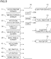
- the motorcycle 1 includes an accelerator sensor 21 that detects an operation amount of the accelerator grip 11, a vehicle speed sensor 22 that detects vehicle speed, a rotation speed sensor 23 that detects rotation speed of the engine 5, a throttle sensor 24 that detects an opening of the electric throttle valve 17 (which will be hereinafter referred to as a throttle opening), a gear position sensor 25 that detects a gear position of the transmission 18, and a bank angle sensor 26 that detects a bank angle.
- the operation amount of the accelerator grip 11 means a rotation position of the accelerator grip 11 from the first rotation position.
- a rotation position from the first rotation position in the opening direction A1 is a positive rotation position
- a rotation position from the first rotation position in the closing direction A2 is a negative rotation position.
- the rotation speed of the engine 5 is rotation speed of the crank shaft 10.
- the accelerator sensor 21, the vehicle speed sensor 22, the gear position sensor 25, and the bank angle sensor 26 are examples of "an accelerator detector,” “a vehicle speed detector,” “a deceleration rate detector,” and “a lean state detector,” respectively.
- the motorcycle 1 includes an electronic control unit (ECU) 30 as a control unit that performs various controls.
- the ECU 30 includes a CPU 30A, a ROM 30B, a RAM 30C, or the like.
- the ECU 30 is communicably coupled to the accelerator sensor 21, the vehicle speed sensor 22, the rotation speed sensor 23, the throttle sensor 24, the gear position sensor 25, and the bank angle sensor 26 and is configured to receive signals from the sensors.
- the ECU 30 is also communicably coupled to the selection switch 41, the set switch 42, the up switch 43, and the down switch 44 and is configured to receive signals from the switches.
- the ECU 30 is communicably coupled to the ignition device 15, the fuel injector 16, and the electric throttle valve 17 and is configured to transmit signals to these components. By controlling the ignition device 15, the fuel injector 16, and the electric throttle valve 17, the ECU 30 controls the output torque of the engine 5.
- the ECU 30 is communicably coupled to the indicator 20 and is configured to transmit a signal to the indicator 20.
- FIG. 10 is a functional block diagram of the ECU 30.
- the ECU 30 executes a computer program stored in the ROM 30B or the like to function as a driving source controller 31, a speed limiter 32, a speed limiter stopping device 34, a display switching device 36, and a cruise controller 35.
- the driving source controller 31 controls the engine 5 such that the output torque of the engine 5 becomes a target torque Tt.
- the speed limiter 32 limits the output torque of the engine 5 such that the vehicle speed does not exceed an upper limit vehicle speed Vs.
- the speed limiter stopping device 34 turns off the speed limiter 32, based on the operation of the accelerator grip 11 by the rider.
- the display switching device 36 receives signals from the switches 41 to 44 and the speed limiter stopping device 34 and switches the display of the indicator 20.
- the cruise controller 35 controls the output torque of the engine 5 such that the vehicle speed is constant set vehicle speed.
- the memory 321 is configured such that the upper limit vehicle speed Vs is rewritable therein. When the rider operates the up switch 43 or the down switch 44 to change the upper limit vehicle speed Vs, the memory 321 stores the changed upper limit vehicle speed Vs.
- the driving source controller 31 includes a rider request torque calculator 311 that calculates a rider request torque Tr, based on the operation amount A of the accelerator grip 11 (which will be hereinafter referred to as an accelerator operation amount), a target torque calculator 312 that calculates the target torque Tt, and a driving controller 313 that controls the engine 5 such that the output torque of the engine 5 becomes the target torque Tt.
- the rider request torque Tr is input to the target torque calculator 312 from the rider request torque calculator 311 and the limit torque Tm is input to the target torque calculator 312 from the limit torque calculator 322.
- the target torque calculator 312 sets the limit torque Tm to the target torque Tt if it is needed to impose a limit on the rider request torque Tr and sets the rider request torque Tr to the target torque Tt if it is not needed to impose a limit on the rider request torque Tr. That is, the target torque calculator 312 sets the rider request torque Tr to the target torque Tt if the limit torque Tm is larger than the rider request torque Tr, and sets the limit torque Tm to the target torque Tt if the limit torque Tm is equal to or less than the rider request torque Tr.
- the target torque Tt calculated in the above-described manner is input to the driving controller 313.
- the driving controller 313 controls the engine 5 such that the engine output torque becomes the target torque Tt.
- the rider can turn off the speed limiter 32 by operating the accelerator grip 11.
- the speed limiter stopping device 34 transmits an off signal to turn off the speed limiter 32, based on the rotation position of the accelerator grip 11.
- the phrase "based on the rotation position of the accelerator grip 11" encompasses both of a case where the off signal is transmitted based on a value of the rotation position of the accelerator grip 11 and a case where the off signal is transmitted based on a change of the value of the rotation position.
- the speed limiter 32 can be turned off.
- As conditions for turning off the speed limiter 32 there are various possible determination conditions. Next, examples of the determination conditions will be described.
- FIG. 11 is a graph illustrating a relationship between an accelerator position ⁇ and a voltage E output by the accelerator sensor 21.
- ⁇ 1 denotes the first rotation position
- ⁇ 2 denotes the second rotation position.
- the speed limiter stopping device 34 may be configured to turn off the speed limiter 32 when the output voltage E of the accelerator sensor 21 becomes E3.
- the rider wants to end the speed limit operation and return to the normal operation while the rider is decelerating the motorcycle 1.
- the rider travels in a designated maximum speed set zone where maximum speed is designated by a road sign or a road mark or a zone where a legal maximum speed is designated.
- the rider wants to return to the normal operation in some cases.
- the rider can turn off the speed limiter 32 by moving the accelerator grip 11 toward the first rotation position ⁇ 1 in the closing direction A2 in order to decelerate and then further moving the accelerator grip 11 to the rotation position ⁇ 3.
- the rider can turn off the speed limiter 32 only by operating the accelerator grip 11 (which will be hereinafter referred to as an accelerator operation) even without operating the set switch 42 of the switch box 13.
- the rider also can turn off the speed limiter 32 by the accelerator operation continuous to the accelerator operation performed for deceleration.
- a smooth accelerator operation is enabled and the speed limit operation can be released without deteriorating the riding feeling.
- an accelerator pedal of an automobile As an accelerator operator of a vehicle, an accelerator pedal of an automobile is known. However, the accelerator pedal is different from the accelerator grip 11 of the motorcycle 1 and cannot be moved farther in the closing direction than a position where an output torque of an engine is minimum. Therefore, in the accelerator pedal, the above-described operation is not possible.
- the speed limiter 32 when the accelerator position ⁇ becomes the second rotation position ⁇ 2, the speed limiter 32 may be turned off.
- the speed limiter stopping device 34 may be configured to turn off the speed limiter 32 when the output voltage of the accelerator sensor 21 becomes E2.
- the rider wants to pass a preceding vehicle during traveling with a vehicle speed limit imposed by the speed limiter 32.
- the vehicle speed does not exceed the upper limit vehicle speed even at acceleration, and therefore, the rider cannot pass the preceding vehicle in some cases.
- the rider can accelerate the motorcycle 1 by rotating the accelerator grip 11 in the opening direction A1 and can turn off the speed limiter 32 by continuously rotating the accelerator grip 11 to the second rotation position ⁇ 2.
- the vehicle speed can be increased to higher speed than the upper limit vehicle speed, so that the rider can pass the preceding vehicle.
- the rider can turn off the speed limiter 32 by the accelerator operation continuous to the accelerator operation performed for acceleration.
- a smooth accelerator operation is enabled and the speed limit operation can be released without deteriorating the riding feeling.
- the rider in order to turn off the speed limiter 32, the rider needs to return the accelerator grip 11 to the rotation position ⁇ 3 that is smaller than the first rotation position ⁇ (see FIG. 11 ). Therefore, the vehicle speed is temporarily reduced. In order to pass the preceding vehicle, the rider needs to decelerate the motorcycle 1 once, and then, accelerate the motorcycle 1.
- the speed limiter 32 can be turned off without decelerating. Therefore, the rider can pass the preceding vehicle without decelerating once.
- the speed limiter stopping device 34 may be configured to turn off the speed limiter 32 immediately after the accelerator position ⁇ has become the second rotation position ⁇ 2 and may be configured to turn off the speed limiter 32 when the accelerator position ⁇ has continued to be the second rotation position ⁇ 2 for a predetermined time. An operation of keeping the accelerator position ⁇ to be the second rotation position ⁇ 2 is not performed without the rider's clear intension. Therefore, the speed limiter 32 can be turned off after the rider's intension is sufficiently confirmed.
- the accelerator grip 11 may be configured to be rotatable farther in the opening direction A1 than the second rotation position ⁇ 2 and the speed limiter 32 may be configured to be turned off when the accelerator position ⁇ becomes a predetermined position ⁇ 4 located farther in the opening direction than the second rotation position ⁇ .
- the speed limiter stopping device 34 may be configured to turn off the speed limiter 32 when the output voltage E of the accelerator sensor 21 becomes E4.
- the rider can accelerate the motorcycle 1 by rotating the accelerator grip 11 toward the second rotation position ⁇ 2 in the opening direction A1.
- the rider can turn off the speed limiter 32 by further rotating the accelerator grip 11 to the rotation position ⁇ 4.
- the rider can turn off the speed limiter 32 by the accelerator operation continuous to the accelerator operation performed for acceleration.
- the speed limiter 32 can be turned off by the smooth accelerator operation.
- the speed limit operation can be released without deteriorating the riding feeling. For example, the rider can smoothly pass the preceding vehicle.
- the speed limiter 32 is not turned off, and it is not until the accelerator position ⁇ becomes the rotation position ⁇ 4 that the speed limiter 32 is turned off. Therefore, the speed limiter 32 can be turned off after the rider's intention has been sufficiently confirmed.
- a resistance force that increases in a stepwise manner may be caused to act on the accelerator grip 11 when the accelerator grip 11 is rotated from the second rotation position ⁇ 2 to the rotation position ⁇ 4.
- a mechanism that applies such a resistance force may be provided in the accelerator grip 11.
- the rider can move the accelerator grip 11 to the rotation position ⁇ 4 by rotating the accelerator grip 11 toward the second rotation position ⁇ 2 and discontinuously increasing a force applied to the accelerator grip 11 after the accelerator grip 11 has reached the second rotation position ⁇ 2.
- the rider can easily recognize that the acceleration position ⁇ has become the second rotation position ⁇ 2 before turning off the speed limiter 32. Therefore, the speed limiter 32 can be turned off after the rider's intention has been sufficiently confirmed.
- the speed limiter 32 may be turned off when ⁇ becomes a preset threshold ⁇ c or more.
- the accelerator position ⁇ is specified by the output voltage of the accelerator sensor 21.
- the speed limiter stopping device 34 may be configured to turn off the speed limiter 32 when a change amount of the output voltage of the accelerator sensor 21 per unit time becomes a preset threshold or more.
- the rider When the rider tries to turn off the speed limiter 32 in accordance with the second determination condition or the third determination condition, the rider needs to change the accelerator position ⁇ to the second rotation position ⁇ 2 or to the rotation position ⁇ 4 that is larger than the second rotation position ⁇ 2. In this case, a large accelerator operation amount is also needed. Accordingly, it takes a relatively long time to perform the accelerator operation. In order to largely change the accelerator position, the rider needs to re-grip the accelerator grip 11 in some cases.
- the rider can turn off the speed limiter 32 only by quickly changing the accelerator position ⁇ . There is no need to largely change the accelerator ⁇ . Accordingly, only a short time is required for the accelerator operation. The rider does not need to re-grip the accelerator grip 11. Thus, a smooth accelerator operation is enabled and the speed limit operation can be released without deteriorating the riding feeling.
- an accelerator pedal of an automobile As described above, as an accelerator operator of a vehicle, an accelerator pedal of an automobile is known.
- the accelerator pedal is stepped on by a driver's foot and not is rotated by a rider's hand.
- the driver can largely move the accelerator pedal only by stepping down the accelerator pedal with the foot kept on the accelerator pedal.
- the driver does not re-step on the accelerator pedal in order to make the accelerator position maximum.
- the rider re-grips the accelerator grip 11 in middle of the accelerator operation in some cases. Therefore, the above-described effect that the rider does not need to re-grip the accelerator grip 11 is an effect unique to a motorcycle that cannot be achieved in an automobile.
- the speed limiter 32 is turned off when the change amount ⁇ of the accelerator position ⁇ per unit time becomes the threshold ⁇ c or more such that the rider can turn off the speed limiter 32 by quickly rotating the accelerator grip 11 in the opening direction A1.
- the speed limiter 32 may be configured to be turned off when the change amount of the accelerator position ⁇ per unit time is a preset negative threshold or less such that the rider can turn off the speed limiter 32 by quickly rotating the accelerator grip 11 in the closing direction A2. That is, the speed limiter 32 may be configured to be turned off when a reduction amount of the accelerator position ⁇ per unit time becomes a predetermined value or more.
- the speed limiter stopping device 34 may be configured to turn off the speed limiter 32 when the accelerator position ⁇ changes in the closing direction by a preset change amount or more after changing in the opening direction by a preset change amount or more within a preset specified time.
- an abscissa indicates the time t and an ordinate indicates the acceleration position ⁇ .
- the rider can turn off the speed limiter 32 by quickly performing an operation of increasing the accelerator position ⁇ and then reducing the accelerator position ⁇ . Similar to the fourth determination condition, there is no need to largely change the accelerator position ⁇ . Therefore, according to the fifth determination condition, only a short time is required for the accelerator operation and the rider does not need to re-grip the accelerator grip 11.
- the speed limiter 32 can be turned off by a smooth accelerator operation. Thus, the speed limit operation can be released without deteriorating the riding feeling.
- the determination conditions when the speed limiter 32 is turned off have been described above.
- the above-described first to fifth determination conditions are merely examples.
- Various other determination conditions are possible.
- a determination condition when the speed limiter 32 is turned off only one of the first to fifth determination conditions may be used. For example, if the first determination condition is satisfied, the speed limiter stopping device 34 turns off the speed limiter 32, but the speed limiter stopping device 34 may be configured not to turn off the speed limiter 32 even if an arbitrary one of the second to fifth determination conditions is satisfied.
- two or more of the first to fifth determination conditions may be used.
- the speed limiter stopping device 34 may be configured to turn off the speed limiter 32 if an arbitrary one of the first determination condition, the third determination condition, or the fifth determination condition is satisfied.
- the rider can turn off the speed limiter 32 by operating the accelerator grip 11.
- the rider does not need to operate the set switch 42 of the switch box 13. Therefore, the rider can easily release the speed limit control.
- the rider can continue the operation of the accelerator grip 11 before and after releasing the speed limit control. Therefore, at a time of releasing the speed limit control, the riding feeling is less likely to be deteriorated.
- the fuel remaining amount is displayed in the second display area 52 of the indicator 20 (see FIG. 4 and FIG. 7 ) and, when the speed limiter 32 is on, it is displayed in the second display area 52 that the speed limiter 32 has been turned on (see FIG. 8 ).
- the second display area 52 that displays the fuel remaining amount it is displayed that the speed limiter 32 has been turned on.
- a dedicated display area that displays that the speed limiter 32 has been turned on is not needed. Therefore, the indicator 20 can be reduced in size.
- the indicator 20 includes the sixth display area 56 in which it is displayed that the fuel remaining amount is a predetermined amount or less. Even in a case where, instead of the fuel remaining amount, it is displayed that the speed limiter 32 has been turned on in the second display area 52, when the fuel remaining amount becomes the predetermined amount or less, the empty mark is displayed in the sixth display area 65 (see FIG. 8 ). Therefore, even when the fuel display amount is not displayed in the second display area 52, the rider can easily know that the duel remaining amount has become the predetermined amount or less.
- the motorcycle 1 includes the selection switch 41 and the set switch 42.
- the selection switch 41 is used as a switch used for selecting the cruise control operation and a switch used for selecting the speed limit operation.
- the set switch 42 is used as a switch used for turning on the cruise controller 35 and a switch used for turning on the speed limiter. According to the motorcycle 1, the same selection switch 41 and the same set switch 42 can be used for both of the cruise controller 35 and the speed limiter 32, and therefore, the number of switches can be reduced.
- the accelerator grip 11 is provided in the right end portion of the handle bar 7 and the selection switch 41 and the set switch 42 are provided in the switch box 13 arranged rightward of a left grip 12 and leftward of the vehicle center line CL.
- the rider can turn on the cruise controller 35 or the speed limiter 32 by operating the selection switch 41 and the set switch 42 with his or her left hand and can turn off the speed limiter 32 by operating the accelerator grip 11 with his or her right hand.
- the motorcycle 1 has a lighter weight than that of an automobile.
- a degree of acceleration that the rider feels increases in some cases. There is a probability that this causes deterioration of the riding feeling.
- a second embodiment is achieved by providing a torque change reducer that reduces a rapid change of the output torque of the engine 5 when the speed limiter 32 is turned off during traveling of the motorcycle 1 in the first embodiment.
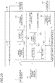
- FIG. 16 is a functional block diagram of the ECU 30 according to this embodiment.
- illustration of the cruise controller 35 and the display switching device 36 is omitted.
- the ECU 30 also functions as the torque change reducer 33 by executing a predetermined computer program.
- the torque change reducer 33 reduces the degree of acceleration when the speed limiter 32 is turned off during traveling of the motorcycle 1. As described above, the limit torque Tm changes with a lapse of time. The torque change reducer 33 limits a change amount of the limit torque Tm.
- the torque change reducer 33 includes a limit value setter 331 and a limit torque adjuster 332.
- the limit value setter 331 sets a limit value Ta of the change amount of the limit torque Tm in accordance with the vehicle state.
- the limit value Ta is set for the change amount of the limit torque Tm such that the limit torque Tm does not excessively increase in a short time.
- the limit torque Tm is input to the limit torque adjuster 332 from the limit torque calculator 322, and the limit value Ta is input to the limit torque adjuster 332 from the limit value setter 331.
- the limit torque adjuster 332 calculates an adjusted limit torque Tf in accordance with procedures described below in every predetermined cycle.
- the limit torque adjuster 332 calculates a limit torque change amount in accordance with Expression 1 below.
- Change amount of Limit torque Limit torque Tm ⁇ Previous calculation value of Adjusted limit torque Tf
- the limit torque adjuster 332 determines whether an absolute value of the change amount of the limit torque is larger than the limit value Ta. If the absolute value of the change amount of the limit torque is larger than the limit value Ta, the limit torque adjuster 332 adjusts the limit torque such that the absolute value of the change amount of the limit torque does not exceed the limit value Ta. That is, the limit torque adjuster 332 adjusts the limit torque such that
- Adjusted limit torque Tf Previous value of Adjusted limit torque Tf + Change amount of Limit torque
- the rider request torque Tr is input to the target torque calculator 312 of the driving source controller 31 from the rider request torque calculator 311 and the adjusted limit torque Tf is input to the target torque calculator 312 from the limit torque adjuster 332.
- the target torque calculator 312 sets the adjusted limit torque Tf to the target torque Tt if it is needed to impose a limit on the rider request torque Tr and sets the rider request torque Tr to the target torque Tt if it is not needed to impose a limit on the rider request torque Tr.
- the target torque calculator 312 sets the adjusted limit torque Tf to the target torque Tt if the adjusted limit torque Tf is smaller than the rider request torque Tr and sets the rider request torque Tr to the target torque Tt if the adjusted limit torque Tf is equal to or more than the rider request torque Tr.
- the "vehicle state" can be specified by values of various parameters detected by the various sensors (see the sensors 21 to 26 in FIG. 4 ) of the motorcycle 1. For example, when a gear position is detected by the gear position sensor 25, a deceleration rate of the transmission 18 is specified. For example, the vehicle state is specified by the deceleration rate of the transmission 18. The vehicle state is specified by the bank angle detected by the bank angle sensor 26. Alternatively, the vehicle state is specified by an angular velocity of the bank angle. Note that the vehicle state may be specified based on a value of a single parameter and may be specified based on values of a plurality of parameters.
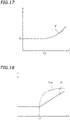
- the motorcycle 1 according to this embodiment includes the torque change reducer 33, and therefore, a rapid increase of the target torque can be avoided. Accordingly, for example, as indicated by a solid line in FIG. 18 , a rapid change of the output torque T of the engine 5 is be reduced. Thus, the riding feeling is improved.
- the degree of reduction is caused to increase as the deceleration rate increases.
- the limit value Ta of the change amount of the limit torque is set such that, as the deceleration rate increases, the limit value Ta reduces.
- the deceleration rate reduces in an order of first speed, second speed, third speed, fourth speed, fifth speed, and sixth speed, and therefore, when respective limit values at the first speed to the sixth speed are Ta1 to Ta6, Ta1 ⁇ Ta2 ⁇ Ta3 ⁇ Ta4 ⁇ Ta5 ⁇ Ta6.
- the limit values Ta2 to Ta6 at the second speed to the sixth speed may be set using the limit value Ta1 at the first speed.
- a map that defines a relationship between the deceleration rate and the limit value Ta may be stored in the ECU 30 in advance and the limit value setter 331 may be configured to read the limit values Ta 1 to Ta6 at the first speed to the sixth speed from the map.
- the motorcycle 1 when turning left or right, the rider leans the vehicle body. There are cases where the rider turns off the speed limiter 32 while the vehicle body leans. In this case, without any action taken, the output torque T of the engine 5 is rapidly increased in some cases (see the broken line in FIG. 18 ). In that case, the degree of acceleration of the vehicle body is increased, and there is a probability that the riding feeling is deteriorated.
- the motorcycle 1 according to this embodiment includes the torque change reducer 33, and therefore, a rapid change of the output torque T of the engine 5 is reduced. Accordingly, the riding feeling is improved.
- the limit value setter 331 sets the limit value Ta such that, as the bank angle increases, the limit value Ta reduces.
- the limit value setter 331 sets the limit value to Ta21 if the bank angle is a first value and sets the limit value to Ta22 that is smaller than Ta21 if the bank angle is a second value that is larger than the first value.
- Ta21 and Ta22 are an example of "a third limit value” and an example of "a fourth limit value,” respectively.
- a change of the output torque T of the engine 5 is more largely reduced as the bank angle increases.
- an increase rate of Tt22' is lower than an increase rate of Tt21'.
- the limit value Ta can be set, for example, using an operational expression, a map, or the like.
- the bank angle is an example of a lean parameter indicating a lean state of the vehicle body.
- the lean parameter is not limited to the bank angle.
- the lean parameter may be angular velocity of the bank angle.
- the limit value setter 331 may be configured to set the limit value Ta in accordance with the angular velocity of the bank angle, instead of the bank angle. Also in this case, a rapid change of the output torque T of the engine 5 is reduced, so that the riding feeling is improved.
- the limit value setter 331 may be configured to set the limit value Ta, based on only the deceleration rate, and may be configured to set the limit value Ta, based on only the bank angle or only the angular velocity of the bank angle. Alternatively, the limit value setter 331 may be configured to set the limit value Ta, based on the deceleration rate and the bank angle or based on the deceleration rate and the angular velocity of the bank angle.
- the limit value setter 331 sets the limit value Ta in accordance with the vehicle state, but a parameter that specifies the vehicle state is not limited to the deceleration rate or the lean parameter related to the lean state of the vehicle body.
- the number of parameters that specify the vehicle state is not limited to one and may be two or more.
- the limit value is set in accordance with the vehicle state and the limit torque is adjusted such that the change amount of the limit torque does not exceed the limit value.
- a change of the output torque of the engine 5 is reduced. Therefore, rapid acceleration when the speed limiter 32 is turned off is reduced, so that the riding feeling can be improved.
- the driving source of the motorcycle 1 is not limited to the internal combustion engine 5 and may be an electric motor.
- the motorcycle 1 may not be capable of performing cruise control.
- the motorcycle 1 may be configured to select the normal operation or the speed limit operation.
- the switch box 13 may be arranged rightward of the vehicle center line CL.
- the area in which it is displayed that the speed limiter 32 has been turned on is not limited to the second display area 52 in which the fuel remaining amount is displayed. It may be displayed in some other area that the speed limiter 32 has been turned on. For example, when the speed limiter 32 is turned on, instead of the gear position, it may be displayed in the third display areas 53 that the speed limiter 32 has been turned on.
- the indicator 20 may include a dedicated display area that displays that the speed limiter 32 has been turned on.
- the fuel remaining amount is an example of “other information” and it is an example of “alternative information” that the fuel remaining amount is the predetermined amount or less.
- other information and “alternative information.”
Landscapes
- Engineering & Computer Science (AREA)
- Mechanical Engineering (AREA)
- Transportation (AREA)
- Chemical & Material Sciences (AREA)
- Combustion & Propulsion (AREA)
- Automation & Control Theory (AREA)
- Control Of Vehicle Engines Or Engines For Specific Uses (AREA)
- Control Of Throttle Valves Provided In The Intake System Or In The Exhaust System (AREA)
- Steering Devices For Bicycles And Motorcycles (AREA)
- Controls For Constant Speed Travelling (AREA)
Abstract
Description
- The present teaching relates to a motorcycle including a speed limiter that limits vehicle speed such that the vehicle speed does not exceed an upper limit.
- Conventionally, motorcycles capable of executing control that causes a motorcycle to travel at constant speed without an operation of an accelerator grip by a rider (that is, cruise control) have been known. For example, in
Japanese Patent Application Publication No. 2010-247681 - Motorcycles which include a speed limiter have been known. For example, in
Japanese Patent Application Publication No. 2009-257270 - A rider can release either of cruise control or speed limit control during traveling of a motorcycle. For example, the rider can release the cruise control or the speed limit control by pressing a button of a switch box.
- Incidentally, in the cruise control, the rider does not operate an accelerator grip. Releasing of the cruise control is performed regardless of an operation of the accelerator grip. On the other hand, in the speed limit control, the rider operates the accelerator grip both before and after releasing the speed limit control. In releasing the speed limit control, depending on a situation of operating the accelerator grip by the rider, it is difficult for the rider to press the button in some cases. Moreover, as compared to an automobile, in a motorcycle, a behavior of a vehicle body more quickly follows an accelerator operation. There is a probability that, if an operation of the accelerator grip is temporarily stopped when the rider presses the button, a riding feeling is deteriorated. Therefore, it is preferable that the speed limit control can be released in conjunction with the operation of the accelerator grip.
- It is therefore an object of the present teaching to provide a motorcycle configured such that an operation of releasing speed limit control is easy and a riding feeling is less likely to be reduced in releasing the speed limit control.
- A motorcycle disclosed herein includes a driving source configured to output a torque that drives a drive wheel, an accelerator grip that is operated by a rider and is rotatable at least between a first rotation position and a second rotation position in an opening direction that is a rotation direction from the first rotation position to the second rotation position and in a closing direction that is a rotation direction from the second rotation position to the first rotation position, an energizing member configured to energize the accelerator grip toward the first rotation position, an accelerator detector configured to detect a rotation position of the accelerator grip, a vehicle speed detector configured to detect vehicle speed, a driving source controller configured to control the driving source, based on the rotation position of the accelerator grip, such that, when the rotation position of the accelerator grip is the first rotation position, the output torque of the driving source is minimum and, when the rotation position of the accelerator grip is the second rotation position, the output torque of the driving source is maximum, a speed limiter configured to limit the output torque of the driving source such that the vehicle speed does not exceed an upper limit, and a speed limiter stopping device configured to turn off the speed limiter, based on the rotation position of the accelerator grip.
- According to the motorcycle, the speed limiter stopping device turns off the speed limiter, based on the rotation position of the accelerator grip, and therefore, the rider can turn off the speed limiter by operating the accelerator grip. Therefore, speed limit control can be easily released. The rider can continue operating the accelerator grip before and after releasing the speed limit control. Therefore, in releasing the speed limit control, a riding feeling is less likely to be deteriorated.
- According to one preferred aspect, the accelerator grip is configured to be rotatable farther in the closing direction than the first rotation position. The speed limiter stopping device is configured to turn off the speed limiter when the rotation position of the accelerator grip becomes a predetermined rotation position located farther in the closing direction than the first rotation position.
- For example, the rider wants to release the speed limit control while the motorcycle decelerates in some cases. According to the aspect, the rider can reduce the vehicle speed by rotating the accelerator grip in the closing direction, and furthermore, can release the speed limit control by rotating the accelerator grip farther in the closing direction than the first rotation position. By the continuous operation of the acceleration grip in the closing direction, deceleration and releasing of the speed limit control can be easily and smoothly performed without deteriorating the riding feeling.
- According to one preferred aspect, the speed limiter stopping device is configured to turn off the speed limiter when the rotation position of the accelerator grip becomes the second rotation position.
- For example, when the rider wants to pass a preceding vehicle, the rider wants to accelerate the motorcycle and also release the speed limit control in some cases. According to the aspect, the rider can increase the vehicle speed by rotating the accelerator grip in the opening direction, and furthermore, can release the speed limit control by rotating the acceleration grip to the second rotation position. By the continuous operation of the acceleration grip in the opening direction, acceleration and releasing of the speed limit control can be easily and smoothly performed without deteriorating the riding feeling.
- According to one preferred aspect, the accelerator grip is configured to be rotatable farther in the opening direction than the second rotation position. The speed limiter stopping device is configured to turn off the speed limiter when the rotation position of the accelerator grip becomes a predetermined rotation position located farther in the opening direction than the second rotation position.
- According to the aspect, the rider can increase the vehicle speed by rotating the accelerator grip in the opening direction, and furthermore, can release the speed limit control by rotating the acceleration grip farther in the opening direction than the second rotation position. By the continuous operation of the acceleration grip in the opening direction, acceleration and releasing of the speed limit control can be easily and smoothly performed without deteriorating the riding feeling.
- According to one preferred aspect, the speed limiter stopping device is configured to turn off the speed limiter when a change amount of the rotation position of the accelerator grip per unit time becomes a preset threshold or more.
- According to the aspect, the rider can release the speed limit control by quickly rotating the accelerator grip in the opening direction. Even when an operation amount of the accelerator grip is not large, the speed limit control can be released. Thus, releasing of the speed limit control can be easily and smoothly performed without deteriorating the riding feeling.
- According to one preferred aspect, the speed limiter stopping device is configured to turn off the speed limiter when the rotation position of the accelerator grip changes in the opening direction by a preset change amount or more and then changes in the closing direction by a preset change amount or more within a preset specified time.
- According to the aspect, by quickly performing an operation of rotating the accelerator grip in the opening direction and an operation of rotating the acceleration grip in the closing direction in a continuous manner, the rider can release the speed limit control even when the operation amount of the acceleration grip in the opening direction and the operation amount of the acceleration grip in the closing direction are not large. Moreover, the speed limit control can be released substantially without changing the vehicle speed. Thus, releasing of the speed limit control can be easily and smoothly performed without deteriorating the riding feeling.
- According to one preferred aspect, the motorcycle further includes an indicator including a first display area configured to display the vehicle speed and a second display area configured to display other information, and a display switching device configured to cause the second display area to display the other information when the speed limiter is off and, cause the second display area to display, instead of the other information, that the speed limiter has been turned on when the speed limiter is on.
- According to the aspect, using the second display area that displays the other information, it can be displayed that the speed limiter has been turned on. In the indicator, a dedicated display area that displays that the speed limiter has been turned on is not needed. Therefore, the indicator can be reduced in size.
- According to one preferred aspect, the indicator includes a display area configured to display alternative information of the other information.
- According to the aspect, even when, in the second display area, instead of the other information, it is displayed that the speed limiter has been turned on, the alternative information of the other information is displayed in the display area. Therefore, while the speed limiter is on, the rider can know at least the alternative information.
- According to one preferred aspect, the motorcycle further includes a cruise controller configured to control the driving source such that the vehicle speed is constant set vehicle speed, a selection switch configured to select a normal operation, a cruise control operation, or a speed limit operation, and a set switch configured to turn on the cruise controller when being operated while the cruise control operation is selected and turn on the speed limiter when being operated while the speed limit operation is selected.
- According to the aspect, the selection switch is used as a switch used for selecting the cruise control operation and a switch used for selecting the speed limit operation. The set switch is used as a switch used for turning on the cruise controller and a switch used for turning on the speed limiter. The same selection switch and the same set switch can be used for the cruise controller and the speed limiter, and therefore, the number of switches can be reduced.
- According to one preferred aspect, the motorcycle further includes a handle bar extending to left and right, a left grip provided in a left end portion of the handle bar, and a switch box arranged rightward of the left grip and leftward of a vehicle center line in the handle bar. The accelerator grip is provided in a right end portion of the handle bar, and the selection switch and the set switch are provided in the switch box.
- According to the aspect, the rider can turn on the cruise controller or the speed limiter by operating the selection switch and the set switch with his/her left hand and can turn off the speed limiter by operating the accelerator grip with his/her right hand.
- According to one preferred aspect, the motorcycle further includes a torque change reducer configured to reduce a change of the output torque of the driving source when the speed limiter is turned off during traveling. The speed limiter includes a memory that stores the upper limit, a deviation calculator configured to calculate a deviation from the upper limit of the vehicle speed detected by the vehicle speed detector, and a limit torque calculator configured to calculate a limit torque, based on the deviation. The torque change reducer includes a limit value setter configured to set a limit value of a change amount of the limit torque in accordance with a vehicle state and a limit torque adjuster configured to receive the limit torque from the limit torque calculator and adjust the limit torque such that the change amount of the limit torque does not exceed the limit value. The driving source controller includes a rider request torque calculator configured to calculate a rider request torque, based on the rotation position of the accelerator grip, and a target torque calculator configured to receive an adjusted limit torque from the limit torque adjuster and calculate the target torque, based on the adjusted limit torque and the rider request torque.
- According to the aspect, if the speed limiter is turned off during traveling, the change amount of the limit torque is limited in accordance with a vehicle state. Thus, a rapid change of the target torque is reduced, and accordingly, a change of the output torque of the driving source is reduced. When the speed limiter is turned off, a rapid change of the output torque of the driving source can be suppressed, and therefore, a riding feeling can be improved.
- According to one preferred aspect, the target torque calculator is configured to, if the speed limiter is turned off during traveling, set the adjusted limit torque to the target torque when the adjusted limit torque is smaller than the rider request torque and set the rider request torque to the target torque when the adjusted limit torque is equal to or more than the rider request torque.
- According to the aspect, an excessive increase of the output torque of the driving source is reduced during acceleration. Therefore, the riding feeling during acceleration can be improved.
- According to one preferred aspect, the motorcycle further includes a transmission including a driving member connected to the driving source and a driven member connected to the drive wheel and configured to change a deceleration rate between the driving member and the driven member, and a deceleration rate detector configured to detect a deceleration rate of the transmission. The limit value setter is configured to set the limit value in accordance with the deceleration rate of the transmission.
- According to the aspect, when the speed limiter is turned off during traveling, rapid acceleration can be avoided in accordance with the deceleration rate, so that the riding feeling can be improved.
- The limit value setter may be configured to set a first limit value as the limit value if the deceleration rate of the transmission is a first deceleration rate, and set a second limit value that is smaller than the first limit value as the limit value if the deceleration rate of the transmission is a second deceleration rate that is higher than the first deceleration rate.
- According to the aspect, if the speed limiter is turned off in turning left or right, rapid acceleration can be avoided in accordance with a degree of a lean of the vehicle body, so that the riding feeling can be improved.
- According to one preferred aspect, the motorcycle further includes a lean state detector configured to detect a lean parameter related to a lean state of the vehicle body. The limit value setter is configured to set the limit value in accordance with a value of the lean parameter.
- According to the aspect, if the speed limiter is turned off while traveling, rapid acceleration can be avoided in accordance with a bank angle or an angular velocity of the bank angle, so that the riding feeling can be improved.
- The lean parameter may be a bank angle of the vehicle body or an angular velocity of the bank angle. The limit value setter may be configured to set a third limit value as the limit value if the value of the lean parameter is a first value, and set a fourth limit value that is smaller than the third limit value as the limit value if the value of the lean parameter is a second value that is larger than the first value.
- According to the present teaching, a motorcycle configured such that an operation of releasing speed limit control is easy and a riding feeling is less likely to be deteriorated in releasing the speed limit control can be provided.
-
-
FIG. 1 is a side view of a motorcycle according to an embodiment. -
FIG. 2 is a cross-sectional view of an internal combustion engine. -
FIG. 3 is a plan view of a handle. -
FIG. 4 is a view illustrating a display image during a normal operation. -
FIG. 5 is a view illustrating a display image when a cruise control operation is selected. -
FIG. 6 is a view illustrating a display image when a speed limit operation is selected. -
FIG. 7 is a view illustrating a display image when the cruise control operation is set. -
FIG. 8 is a view illustrating a display image when the speed limit operation is set. -
FIG. 9 is a block diagram illustrating sensors, switches, an ECU, and target devices to be controlled. -
FIG. 10 is a functional block diagram of a control system according to a first embodiment. -
FIG. 11 is a graph illustrating a first determination condition, illustrating a relationship between a rotation position of an accelerator grip and an output voltage of an accelerator sensor. -
FIG. 12 is a graph illustrating a second determination condition, illustrating a relationship between the rotation position of the accelerator grip and the output voltage of the accelerator sensor. -
FIG. 13 is a graph illustrating a third determination condition, illustrating a relationship between the rotation position of the accelerator grip and the output voltage of the accelerator sensor. -
FIG. 14 is a graph illustrating a fourth determination condition, illustrating a change of a change amount of the rotation position of the accelerator grip per unit time with time. -
FIG. 15 is a graph illustrating a fifth determination condition, illustrating a change of the rotation position of the accelerator grip per unit time with time. -
FIG. 16 is a functional block diagram of a control system according to a second embodiment. -
FIG. 17 is a graph illustrating an example of a change of vehicle speed with time. -
FIG. 18 is a graph illustrating an example of a change of an output torque. -
FIG. 19 is a graph illustrating an example of a change of the output torque for each deceleration rate. -
FIG. 20 is a graph illustrating an example of a change of the output torque for each bank angle. - With reference to the attached drawings, embodiments will be described below.
FIG. 1 is a side view of amotorcycle 1 according to an embodiment. Themotorcycle 1 includes a front wheel 2, a rear wheel 3, a vehicle body 4 supported by the front wheel 2 and the rear wheel 3, and an internal combustion engine (which will be hereinafter referred to as an engine) 5 supported by the vehicle body 4. Theengine 5 is an example of a "driving source" that outputs a torque that drives the rear wheel 3. The vehicle body 4 includes a handle bar 7, a steering shaft 8 with the handle bar 7 attached thereto, a seat 9 on which a rider sits, and anindicator 20 that displays vehicle speed or the like. - As illustrated in
FIG. 2 , theengine 5 includes apiston 19 and acrank shaft 10 connected to thepiston 19. A clutch 40 is coupled to thecrank shaft 10. Atransmission 18 is coupled to the clutch 40. - The
transmission 18 includes a drivingmember 18A coupled to theengine 5 and a drivenmember 18B connected to the rear wheel 3. In this embodiment, thetransmission 18 is a multistep transmission. The drivingmember 18A includes a drivingshaft 18a and a plurality of drivinggears 18b. The drivenmember 18B includes a drivenshaft 18c and a plurality of drivengears 18d. In thetransmission 18, a torque is transmitted from the drivingmember 18A to the drivenmember 18B. Thetransmission 18 is configured to change a deceleration rate. The deceleration rate herein is a ratio of rotation speed of the drivingmember 18A to rotation speed of the drivenmember 18B. That is, the deceleration rate = (the rotation speed of the drivingmember 18A)/(the rotation speed of the drivenmember 18B). The drivenmember 18B of thetransmission 18 and the rear wheel 3 are connected to each other via a power transmission member, such as a chain or the like. Note that there is no particular limitation on the number of shift steps of thetransmission 18 but the number of shift steps is, for example, six. Thetransmission 18 is not limited to a multistep transmission and may be a continuously variable transmission, such as a CVT or the like. - As illustrated in
FIG. 3 , arotatable accelerator grip 11 is provided in a right end portion of the handle bar 7. Theaccelerator grip 11 is rotatable in an opening direction A1 and a closing direction A2. Herein, the opening direction A1 is a counterclockwise direction when viewed from a right side. The closing direction A2 is a direction opposite to the opening direction A1, that is, a clockwise direction when viewed from a right side. Theaccelerator grip 11 is rotatable at least between a first rotation position and a second rotation position. The first rotation position is a so-called full close position. When a rotation position of the accelerator grip 11 (which will be hereinafter simply referred to as an accelerator position) is the first rotation position, an output torque of theengine 5 is minimum. The second rotation position is a so-called full open position. When the accelerator position is the second rotation position, the output torque of theengine 5 is maximum. Areturn spring 14 that energizes the accelerator position toward the first rotation position is provided in theaccelerator grip 11. Thereturn spring 14 is an example of an "energizing member". When the rider releases his or her hand from theaccelerator grip 11, theaccelerator grip 11 automatically returns to the first rotation position. - A nonrotatable
fixed grip 12 and aswitch box 13 are provided in a left end portion of the handle bar 7. Theswitch box 13 is arranged rightward of the fixedgrip 12 and leftward of a vehicle center line CL. In theswitch box 13, aselection switch 41, aset switch 42, an upswitch 43, and adown switch 44 are provided. There is no particular limitation on forms of theswitches 41 to 44, but theswitches 41 to 44 are constituted by button type switches herein. Switches provided in theswitch box 13 are not limited to theswitches 41 to 44. Some other switch may be provided in theswitch box 13. - In the
motorcycle 1 according to this embodiment, a normal operation, a cruise control operation in which themotorcycle 1 travels at constant speed regardless of an operation of theaccelerator grip 11, and a speed limit operation in which vehicle speed is limited such that the vehicle speed does not exceed an upper limit are possible. Theselection switch 41 is a switch used for selecting a type of operation. Herein, each time theselection switch 41 is pressed, the normal operation, the cruise control operation, and the speed limit operation are selected in order. Theset switch 42 is a switch used for switching on and off of the cruise control operation or the speed limit operation. The upswitch 43 and thedown switch 44 are used, for example, for setting or changing an upper limit of vehicle speed of the limit operation (which will be hereinafter referred to as an upper limit vehicle speed). When the rider operates theup switch 43, the upper limit vehicle speed is increased and, when the rider operates thedown switch 44, the upper limit vehicle speed is reduced. - As illustrated in
FIG. 4 , theindicator 20 includes adisplay screen 50 that displays information. Thedisplay screen 50 includes first tosixth display areas 51 to 56. The vehicle speed is displayed in thefirst display area 51. A fuel remaining amount can be displayed in thesecond display area 52. A gear position can be displayed in thethird display areas 53. A character, a symbol, or the like (which will be hereinafter referred to as an empty mark) that indicates that the fuel remaining amount is a predetermined amount or less is displayed in thesixth display area 56. - As described above, each time the
selection switch 41 is pressed, the normal operation, the cruise control operation, and the speed limit operation are selected in order.FIG. 4 ,FIG. 5, and FIG. 6 illustrate a display when the normal operation is selected, a display when the cruise control operation is selected, and a display when the speed limit operation is selected, respectively. - As illustrated in
FIG. 5 , a character, a symbol, or the like that indicates that the cruise control operation has been selected is displayed in the fourth display are 54.FIG. 7 illustrates a display when the cruise control operation is turned on. When theset switch 42 is pressed in a state where the cruise control operation has been selected as illustrated inFIG. 5 , as illustrated inFIG. 7 , a character, a symbol, or the like that indicates that the cruise control operation is being executed is displayed in thefifth display area 55. When theset switch 42 is pressed during execution of the cruise control operation, a display of thefifth display area 55 is cleared (seeFIG. 5 ). - As illustrated in
FIG. 6 , when the speed limit operation is selected, instead of the fuel remaining amount, a character, a symbol, or the like that indicates that the speed limit operation has been selected is displayed in thesecond display area 52. When theset switch 42 is pressed in a state where the speed limit operation is selected, as illustrated inFIG. 8 , a character or a symbol that indicates that the speed limit operation is being executed and the upper limit vehicle speed are further displayed in thesecond display area 52. When the speed limit operation is released, a display of thesecond display area 52 is switched from a display of the character or the like that indicates that the speed limit operation is being executed and the upper limit vehicle speed to a display of the fuel remaining amount. That is, a display of theindicator 20 is switched from a display illustrated inFIG. 8 to a display illustrated inFIG. 6 . - As illustrated in
FIG. 8 , when the fuel remaining amount is a predetermined amount or less, the empty mark is displayed in thesixth display area 56. Information represented by the empty mark indicates whether the fuel remaining amount is the predetermined amount or less, that is, alternative information of the information that is the fuel remaining amount. That is, when it is assumed that the fuel remaining amount displayed in thesecond display area 52 is "the other information," information displayed in thesixth display area 56 is "alternative information" of "the other information." The alternative information is information including a part or a whole of information included in the other information. If the speed limit operation is being executed, in thesecond display area 52, instead of the fuel remaining amount, it is displayed that the speed limit operation is being executed or the like. However, when the fuel remaining amount is the predetermined amount or less, the empty mark is displayed in thesixth display area 56. Therefore, even when the fuel remaining amount is not displayed in thesecond display area 52, the rider can easily know that the fuel remaining amount is the predetermined amount or less. - As illustrated in
FIG. 9 , theengine 5 includes anignition device 15, afuel injector 16, and anelectric throttle valve 17. Theignition device 15, thefuel injector 16, and theelectric throttle valve 17 are operated, so that a torque output by the engine 5 (which will be hereinafter referred to as an output torque) is controlled. - The
motorcycle 1 includes anaccelerator sensor 21 that detects an operation amount of theaccelerator grip 11, avehicle speed sensor 22 that detects vehicle speed, arotation speed sensor 23 that detects rotation speed of theengine 5, athrottle sensor 24 that detects an opening of the electric throttle valve 17 (which will be hereinafter referred to as a throttle opening), agear position sensor 25 that detects a gear position of thetransmission 18, and abank angle sensor 26 that detects a bank angle. In this embodiment, the operation amount of theaccelerator grip 11 means a rotation position of theaccelerator grip 11 from the first rotation position. Herein, a rotation position from the first rotation position in the opening direction A1 is a positive rotation position, and a rotation position from the first rotation position in the closing direction A2 is a negative rotation position. As the rotation position (in other words, a rotation angle) of theaccelerator grip 11 increases, the operation amount of theaccelerator grip 11 increases. The rotation speed of theengine 5 is rotation speed of thecrank shaft 10. Theaccelerator sensor 21, thevehicle speed sensor 22, thegear position sensor 25, and thebank angle sensor 26 are examples of "an accelerator detector," "a vehicle speed detector," "a deceleration rate detector," and "a lean state detector," respectively. - The
motorcycle 1 includes an electronic control unit (ECU) 30 as a control unit that performs various controls. TheECU 30 includes aCPU 30A, aROM 30B, aRAM 30C, or the like. TheECU 30 is communicably coupled to theaccelerator sensor 21, thevehicle speed sensor 22, therotation speed sensor 23, thethrottle sensor 24, thegear position sensor 25, and thebank angle sensor 26 and is configured to receive signals from the sensors. TheECU 30 is also communicably coupled to theselection switch 41, theset switch 42, the upswitch 43, and thedown switch 44 and is configured to receive signals from the switches. TheECU 30 is communicably coupled to theignition device 15, thefuel injector 16, and theelectric throttle valve 17 and is configured to transmit signals to these components. By controlling theignition device 15, thefuel injector 16, and theelectric throttle valve 17, theECU 30 controls the output torque of theengine 5. TheECU 30 is communicably coupled to theindicator 20 and is configured to transmit a signal to theindicator 20. -
FIG. 10 is a functional block diagram of theECU 30. TheECU 30 executes a computer program stored in theROM 30B or the like to function as a drivingsource controller 31, aspeed limiter 32, a speedlimiter stopping device 34, adisplay switching device 36, and acruise controller 35. In accordance with an operation of theaccelerator grip 11 by the rider, the drivingsource controller 31 controls theengine 5 such that the output torque of theengine 5 becomes a target torque Tt. Thespeed limiter 32 limits the output torque of theengine 5 such that the vehicle speed does not exceed an upper limit vehicle speed Vs. The speedlimiter stopping device 34 turns off thespeed limiter 32, based on the operation of theaccelerator grip 11 by the rider. Thedisplay switching device 36 receives signals from theswitches 41 to 44 and the speedlimiter stopping device 34 and switches the display of theindicator 20. Thecruise controller 35 controls the output torque of theengine 5 such that the vehicle speed is constant set vehicle speed. - The
speed limiter 32 includes amemory 321 that stores the upper limit vehicle speed Vs, adeviation calculator 323 that calculates a deviation ΔV = Vs - V from the upper limit vehicle speed Vs of the vehicle speed V, and alimit torque calculator 322 that calculates a limit torque Tm, at least based on the deviation AV. Thememory 321 is configured such that the upper limit vehicle speed Vs is rewritable therein. When the rider operates theup switch 43 or thedown switch 44 to change the upper limit vehicle speed Vs, thememory 321 stores the changed upper limit vehicle speed Vs. There is no particular limitation on a method for calculating the limit torque Tm in thelimit torque calculator 322. Herein, the limit torque Tm is calculated as the limit torque Tm = a predetermined feedback gain × the deviation ΔV + a predetermined travel resistance feedforward torque. Note that the limit torque Tm is a parameter that changes with a lapse of time. - The driving
source controller 31 includes a riderrequest torque calculator 311 that calculates a rider request torque Tr, based on the operation amount A of the accelerator grip 11 (which will be hereinafter referred to as an accelerator operation amount), atarget torque calculator 312 that calculates the target torque Tt, and a drivingcontroller 313 that controls theengine 5 such that the output torque of theengine 5 becomes the target torque Tt. The rider request torque Tr is input to thetarget torque calculator 312 from the riderrequest torque calculator 311 and the limit torque Tm is input to thetarget torque calculator 312 from thelimit torque calculator 322. Thetarget torque calculator 312 sets the limit torque Tm to the target torque Tt if it is needed to impose a limit on the rider request torque Tr and sets the rider request torque Tr to the target torque Tt if it is not needed to impose a limit on the rider request torque Tr. That is, thetarget torque calculator 312 sets the rider request torque Tr to the target torque Tt if the limit torque Tm is larger than the rider request torque Tr, and sets the limit torque Tm to the target torque Tt if the limit torque Tm is equal to or less than the rider request torque Tr. The target torque Tt calculated in the above-described manner is input to the drivingcontroller 313. The drivingcontroller 313 controls theengine 5 such that the engine output torque becomes the target torque Tt. - In the
motorcycle 1 according to this embodiment, the rider can turn off thespeed limiter 32 by operating theaccelerator grip 11. The speedlimiter stopping device 34 transmits an off signal to turn off thespeed limiter 32, based on the rotation position of theaccelerator grip 11. Note that the phrase "based on the rotation position of theaccelerator grip 11" encompasses both of a case where the off signal is transmitted based on a value of the rotation position of theaccelerator grip 11 and a case where the off signal is transmitted based on a change of the value of the rotation position. When a predetermined condition related to the rotation position of theaccelerator grip 11 is satisfied, thespeed limiter 32 is turned off by the speedlimiter stopping device 34. The speedlimiter stopping device 34 determines whether the predetermined condition is satisfied and, if the speedlimiter stopping device 34 determines that the predetermined condition is satisfied, the speedlimiter stopping device 34 transmits the off signal. - By various operations of the
accelerator grip 11, thespeed limiter 32 can be turned off. As conditions for turning off thespeed limiter 32, there are various possible determination conditions. Next, examples of the determination conditions will be described. - For example, the
accelerator grip 11 may be configured to be rotatable farther in the closing direction than the first rotation position and thespeed limiter 32 may be configured to be turned off when the acceleration position becomes a predetermined rotation position located farther in the closing direction than the first rotation position.FIG. 11 is a graph illustrating a relationship between an accelerator position α and a voltage E output by theaccelerator sensor 21. InFIG. 11 , α1 denotes the first rotation position and α2 denotes the second rotation position. When the accelerator position α is between the first rotation position α1 and the second rotation position α2, as the accelerator position α increases, the output voltage E increases. When α = α1, E = E1 and, when α = α2, E = E2. When the accelerator position α becomes a predetermined rotation position α3 located farther in the closing direction A2 than the first rotation position α1 or less, the output voltage E is E3 that is lower than E1. The speedlimiter stopping device 34 may be configured to turn off thespeed limiter 32 when the output voltage E of theaccelerator sensor 21 becomes E3. - For example, there are cases where the rider wants to end the speed limit operation and return to the normal operation while the rider is decelerating the
motorcycle 1. For example, in some cases, the rider travels in a designated maximum speed set zone where maximum speed is designated by a road sign or a road mark or a zone where a legal maximum speed is designated. In traveling in such a zone with a vehicle speed limit imposed by thespeed limiter 32, while the rider is decelerating before a last red light in the zone, the rider wants to return to the normal operation in some cases. In such a case, the rider can turn off thespeed limiter 32 by moving theaccelerator grip 11 toward the first rotation position α1 in the closing direction A2 in order to decelerate and then further moving theaccelerator grip 11 to the rotation position α3. The rider can turn off thespeed limiter 32 only by operating the accelerator grip 11 (which will be hereinafter referred to as an accelerator operation) even without operating theset switch 42 of theswitch box 13. The rider also can turn off thespeed limiter 32 by the accelerator operation continuous to the accelerator operation performed for deceleration. Thus, a smooth accelerator operation is enabled and the speed limit operation can be released without deteriorating the riding feeling. - As an accelerator operator of a vehicle, an accelerator pedal of an automobile is known. However, the accelerator pedal is different from the
accelerator grip 11 of themotorcycle 1 and cannot be moved farther in the closing direction than a position where an output torque of an engine is minimum. Therefore, in the accelerator pedal, the above-described operation is not possible. - As illustrated in
FIG. 12 , when the accelerator position α becomes the second rotation position α2, thespeed limiter 32 may be turned off. The speedlimiter stopping device 34 may be configured to turn off thespeed limiter 32 when the output voltage of theaccelerator sensor 21 becomes E2. - For example, there are cases where the rider wants to pass a preceding vehicle during traveling with a vehicle speed limit imposed by the
speed limiter 32. However, with the vehicle speed limit kept imposed, the vehicle speed does not exceed the upper limit vehicle speed even at acceleration, and therefore, the rider cannot pass the preceding vehicle in some cases. According to a second determination condition, the rider can accelerate themotorcycle 1 by rotating theaccelerator grip 11 in the opening direction A1 and can turn off thespeed limiter 32 by continuously rotating theaccelerator grip 11 to the second rotation position α2. Thus, the vehicle speed can be increased to higher speed than the upper limit vehicle speed, so that the rider can pass the preceding vehicle. The rider can turn off thespeed limiter 32 by the accelerator operation continuous to the accelerator operation performed for acceleration. Thus, a smooth accelerator operation is enabled and the speed limit operation can be released without deteriorating the riding feeling. - According to the above-described first determination condition, in order to turn off the
speed limiter 32, the rider needs to return theaccelerator grip 11 to the rotation position α3 that is smaller than the first rotation position α (seeFIG. 11 ). Therefore, the vehicle speed is temporarily reduced. In order to pass the preceding vehicle, the rider needs to decelerate themotorcycle 1 once, and then, accelerate themotorcycle 1. However, according to the second determination condition, thespeed limiter 32 can be turned off without decelerating. Therefore, the rider can pass the preceding vehicle without decelerating once. - Note that the speed
limiter stopping device 34 may be configured to turn off thespeed limiter 32 immediately after the accelerator position α has become the second rotation position α2 and may be configured to turn off thespeed limiter 32 when the accelerator position α has continued to be the second rotation position α2 for a predetermined time. An operation of keeping the accelerator position α to be the second rotation position α2 is not performed without the rider's clear intension. Therefore, thespeed limiter 32 can be turned off after the rider's intension is sufficiently confirmed. - As illustrated in
FIG. 13 , with theaccelerator grip 11 may be configured to be rotatable farther in the opening direction A1 than the second rotation position α2 and thespeed limiter 32 may be configured to be turned off when the accelerator position α becomes a predetermined position α4 located farther in the opening direction than the second rotation position α. In this case, when the accelerator position α becomes α4 or more, the output voltage E becomes E4 that is higher than E2. The speedlimiter stopping device 34 may be configured to turn off thespeed limiter 32 when the output voltage E of theaccelerator sensor 21 becomes E4. - According to the third determination condition, the rider can accelerate the
motorcycle 1 by rotating theaccelerator grip 11 toward the second rotation position α2 in the opening direction A1. The rider can turn off thespeed limiter 32 by further rotating theaccelerator grip 11 to the rotation position α4. Accordingly, the rider can turn off thespeed limiter 32 by the accelerator operation continuous to the accelerator operation performed for acceleration. Thespeed limiter 32 can be turned off by the smooth accelerator operation. Moreover, when passing a preceding vehicle, there is no need to decelerate themotorcycle 1 once. Thus, the speed limit operation can be released without deteriorating the riding feeling. For example, the rider can smoothly pass the preceding vehicle. - According to the third determination condition, even when the accelerator position α becomes the second rotation position α2, the
speed limiter 32 is not turned off, and it is not until the accelerator position α becomes the rotation position α4 that thespeed limiter 32 is turned off. Therefore, thespeed limiter 32 can be turned off after the rider's intention has been sufficiently confirmed. - A resistance force that increases in a stepwise manner may be caused to act on the
accelerator grip 11 when theaccelerator grip 11 is rotated from the second rotation position α2 to the rotation position α4. A mechanism that applies such a resistance force may be provided in theaccelerator grip 11. Thus, the rider can move theaccelerator grip 11 to the rotation position α4 by rotating theaccelerator grip 11 toward the second rotation position α2 and discontinuously increasing a force applied to theaccelerator grip 11 after theaccelerator grip 11 has reached the second rotation position α2. The rider can easily recognize that the acceleration position α has become the second rotation position α2 before turning off thespeed limiter 32. Therefore, thespeed limiter 32 can be turned off after the rider's intention has been sufficiently confirmed. - In
FIG. 14 , an abscissa indicates a time t and an ordinate indicates a change amount β = Δα/Δt of the accelerator position α per unit time. As illustrated inFIG. 14 , thespeed limiter 32 may be turned off when β becomes a preset threshold βc or more. The accelerator position α is specified by the output voltage of theaccelerator sensor 21. The speedlimiter stopping device 34 may be configured to turn off thespeed limiter 32 when a change amount of the output voltage of theaccelerator sensor 21 per unit time becomes a preset threshold or more. - For example, there are cases where the rider wants to end the speed limit operation and return to the normal operation while the accelerator position α is located in an intermediate position between the first rotation position α1 and the second rotation position α2. In such a case, when the rider tries to turn off the
speed limiter 32 according to the first determination condition, the rider needs to change the accelerator position α to the first rotation position α1 and then further change the accelerator position α to the rotation position α3 that is smaller than the first rotation position α1. Therefore, a large acceleration operation amount is needed. When the rider tries to turn off thespeed limiter 32 in accordance with the second determination condition or the third determination condition, the rider needs to change the accelerator position α to the second rotation position α2 or to the rotation position α4 that is larger than the second rotation position α2. In this case, a large accelerator operation amount is also needed. Accordingly, it takes a relatively long time to perform the accelerator operation. In order to largely change the accelerator position, the rider needs to re-grip theaccelerator grip 11 in some cases. - However, according to the fourth determination condition, the rider can turn off the
speed limiter 32 only by quickly changing the accelerator position α. There is no need to largely change the accelerator α. Accordingly, only a short time is required for the accelerator operation. The rider does not need to re-grip theaccelerator grip 11. Thus, a smooth accelerator operation is enabled and the speed limit operation can be released without deteriorating the riding feeling. - As described above, as an accelerator operator of a vehicle, an accelerator pedal of an automobile is known. The accelerator pedal is stepped on by a driver's foot and not is rotated by a rider's hand. The driver can largely move the accelerator pedal only by stepping down the accelerator pedal with the foot kept on the accelerator pedal. The driver does not re-step on the accelerator pedal in order to make the accelerator position maximum. On the other hand, in the
motorcycle 1, the rider re-grips theaccelerator grip 11 in middle of the accelerator operation in some cases. Therefore, the above-described effect that the rider does not need to re-grip theaccelerator grip 11 is an effect unique to a motorcycle that cannot be achieved in an automobile. - According to this condition, the
speed limiter 32 is turned off when the change amount β of the accelerator position α per unit time becomes the threshold βc or more such that the rider can turn off thespeed limiter 32 by quickly rotating theaccelerator grip 11 in the opening direction A1. However, the present teaching is not limited thereto. Thespeed limiter 32 may be configured to be turned off when the change amount of the accelerator position α per unit time is a preset negative threshold or less such that the rider can turn off thespeed limiter 32 by quickly rotating theaccelerator grip 11 in the closing direction A2. That is, thespeed limiter 32 may be configured to be turned off when a reduction amount of the accelerator position α per unit time becomes a predetermined value or more. - The speed
limiter stopping device 34 may be configured to turn off thespeed limiter 32 when the accelerator position α changes in the closing direction by a preset change amount or more after changing in the opening direction by a preset change amount or more within a preset specified time. - In
FIG. 15 , an abscissa indicates the time t and an ordinate indicates the acceleration position α. For example, as illustrated inFIG. 15 , assume that, during the specified time Δt, the accelerator position α has changed from α11 to α12 and then α12 to α13. The speedlimiter stopping device 34 may be configured to turn off thespeed limiter 32 if Δα1 = α12 - α11 is a preset change amount k1 or more and Δα2 = α12 - α13 is a preset change amount k2 or more. Note that k1 and k2 may be equal to each other and may be different from each other. - According to the fifth determination condition, the rider can turn off the
speed limiter 32 by quickly performing an operation of increasing the accelerator position α and then reducing the accelerator position α. Similar to the fourth determination condition, there is no need to largely change the accelerator position α. Therefore, according to the fifth determination condition, only a short time is required for the accelerator operation and the rider does not need to re-grip theaccelerator grip 11. Thespeed limiter 32 can be turned off by a smooth accelerator operation. Thus, the speed limit operation can be released without deteriorating the riding feeling. - Examples of the determination conditions when the
speed limiter 32 is turned off have been described above. However, the above-described first to fifth determination conditions are merely examples. Various other determination conditions are possible. As a determination condition when thespeed limiter 32 is turned off, only one of the first to fifth determination conditions may be used. For example, if the first determination condition is satisfied, the speedlimiter stopping device 34 turns off thespeed limiter 32, but the speedlimiter stopping device 34 may be configured not to turn off thespeed limiter 32 even if an arbitrary one of the second to fifth determination conditions is satisfied. Alternatively, as determination conditions when thespeed limiter 32 is turned off, two or more of the first to fifth determination conditions may be used. For example, the speedlimiter stopping device 34 may be configured to turn off thespeed limiter 32 if an arbitrary one of the first determination condition, the third determination condition, or the fifth determination condition is satisfied. - As described above, according to the
motorcycle 1 according to this embodiment, the rider can turn off thespeed limiter 32 by operating theaccelerator grip 11. In order to turn off thespeed limiter 32, the rider does not need to operate theset switch 42 of theswitch box 13. Therefore, the rider can easily release the speed limit control. Moreover, the rider can continue the operation of theaccelerator grip 11 before and after releasing the speed limit control. Therefore, at a time of releasing the speed limit control, the riding feeling is less likely to be deteriorated. - According to the
motorcycle 1, when thespeed limiter 32 is off, the fuel remaining amount is displayed in thesecond display area 52 of the indicator 20 (seeFIG. 4 andFIG. 7 ) and, when thespeed limiter 32 is on, it is displayed in thesecond display area 52 that thespeed limiter 32 has been turned on (seeFIG. 8 ). Using thesecond display area 52 that displays the fuel remaining amount, it is displayed that thespeed limiter 32 has been turned on. In theindicator 20, a dedicated display area that displays that thespeed limiter 32 has been turned on is not needed. Therefore, theindicator 20 can be reduced in size. - The
indicator 20 includes thesixth display area 56 in which it is displayed that the fuel remaining amount is a predetermined amount or less. Even in a case where, instead of the fuel remaining amount, it is displayed that thespeed limiter 32 has been turned on in thesecond display area 52, when the fuel remaining amount becomes the predetermined amount or less, the empty mark is displayed in the sixth display area 65 (seeFIG. 8 ). Therefore, even when the fuel display amount is not displayed in thesecond display area 52, the rider can easily know that the duel remaining amount has become the predetermined amount or less. - According to the
motorcycle 1, the normal operation, the cruise control operation, and the speed limit operation are possible. Themotorcycle 1 includes theselection switch 41 and theset switch 42. Theselection switch 41 is used as a switch used for selecting the cruise control operation and a switch used for selecting the speed limit operation. Theset switch 42 is used as a switch used for turning on thecruise controller 35 and a switch used for turning on the speed limiter. According to themotorcycle 1, thesame selection switch 41 and thesame set switch 42 can be used for both of thecruise controller 35 and thespeed limiter 32, and therefore, the number of switches can be reduced. - According to the
motorcycle 1, as illustrated inFIG. 3 , theaccelerator grip 11 is provided in the right end portion of the handle bar 7 and theselection switch 41 and theset switch 42 are provided in theswitch box 13 arranged rightward of aleft grip 12 and leftward of the vehicle center line CL. The rider can turn on thecruise controller 35 or thespeed limiter 32 by operating theselection switch 41 and theset switch 42 with his or her left hand and can turn off thespeed limiter 32 by operating theaccelerator grip 11 with his or her right hand. - The
motorcycle 1 has a lighter weight than that of an automobile. Depending on a vehicle state when thespeed limiter 32 has been turned off, a degree of acceleration that the rider feels increases in some cases. There is a probability that this causes deterioration of the riding feeling. Thus, a configuration in which, depending on the vehicle state when thespeed limiter 32 has been turned off, a rapid change of the output torque of theengine 5 is reduced may be employed. A second embodiment is achieved by providing a torque change reducer that reduces a rapid change of the output torque of theengine 5 when thespeed limiter 32 is turned off during traveling of themotorcycle 1 in the first embodiment. In the following description, the same portions as those in the first embodiment are denoted by the same reference numerals and the description thereof will be omitted. -
FIG. 16 is a functional block diagram of theECU 30 according to this embodiment. InFIG. 16 , illustration of thecruise controller 35 and thedisplay switching device 36 is omitted. In this embodiment, theECU 30 also functions as thetorque change reducer 33 by executing a predetermined computer program. - The
torque change reducer 33 reduces the degree of acceleration when thespeed limiter 32 is turned off during traveling of themotorcycle 1. As described above, the limit torque Tm changes with a lapse of time. Thetorque change reducer 33 limits a change amount of the limit torque Tm. Thetorque change reducer 33 includes alimit value setter 331 and alimit torque adjuster 332. When thespeed limiter 32 is turned off during traveling of themotorcycle 1, thelimit value setter 331 sets a limit value Ta of the change amount of the limit torque Tm in accordance with the vehicle state. The limit value Ta is set for the change amount of the limit torque Tm such that the limit torque Tm does not excessively increase in a short time. - The limit torque Tm is input to the
limit torque adjuster 332 from thelimit torque calculator 322, and the limit value Ta is input to thelimit torque adjuster 332 from thelimit value setter 331. Thelimit torque adjuster 332 calculates an adjusted limit torque Tf in accordance with procedures described below in every predetermined cycle. - First, the
limit torque adjuster 332 calculates a limit torque change amount in accordance withExpression 1 below.
- Note that there is no previous calculation value of the adjusted limit torque Tf at a start of control. Therefore, a rider request torque Tr is regarded as the previous calculation value of the adjusted limit torque Tf.
- Next, the
limit torque adjuster 332 determines whether an absolute value of the change amount of the limit torque is larger than the limit value Ta. If the absolute value of the change amount of the limit torque is larger than the limit value Ta, thelimit torque adjuster 332 adjusts the limit torque such that the absolute value of the change amount of the limit torque does not exceed the limit value Ta. That is, thelimit torque adjuster 332 adjusts the limit torque such that |the change amount of the limit torque| ≤ the limit value Ta. - Lastly, the
limit torque adjuster 332 calculates the adjusted limit torque Tf in accordance with Expression 2 described below.
- The rider request torque Tr is input to the
target torque calculator 312 of the drivingsource controller 31 from the riderrequest torque calculator 311 and the adjusted limit torque Tf is input to thetarget torque calculator 312 from thelimit torque adjuster 332. Thetarget torque calculator 312 sets the adjusted limit torque Tf to the target torque Tt if it is needed to impose a limit on the rider request torque Tr and sets the rider request torque Tr to the target torque Tt if it is not needed to impose a limit on the rider request torque Tr. That is, if thespeed limiter 32 is turned off during traveling, thetarget torque calculator 312 sets the adjusted limit torque Tf to the target torque Tt if the adjusted limit torque Tf is smaller than the rider request torque Tr and sets the rider request torque Tr to the target torque Tt if the adjusted limit torque Tf is equal to or more than the rider request torque Tr. - The "vehicle state" can be specified by values of various parameters detected by the various sensors (see the
sensors 21 to 26 inFIG. 4 ) of themotorcycle 1. For example, when a gear position is detected by thegear position sensor 25, a deceleration rate of thetransmission 18 is specified. For example, the vehicle state is specified by the deceleration rate of thetransmission 18. The vehicle state is specified by the bank angle detected by thebank angle sensor 26. Alternatively, the vehicle state is specified by an angular velocity of the bank angle. Note that the vehicle state may be specified based on a value of a single parameter and may be specified based on values of a plurality of parameters. - As illustrated in
FIG. 17 , there are cases where, while themotorcycle 1 travels at the upper limit vehicle speed Vs with a limit imposed on themotorcycle 1 by thespeed limiter 32, thespeed limiter 32 is turned off at the time t1 and the vehicle speed V is increased. If the limit torque Tm immediately before thespeed limiter 32 is turned off is large, without any action taken, the target torque is rapidly increased in some cases and, for example, as indicated by a broken line inFIG. 18 , the output torque T of theengine 5 is rapidly increased. Thus, the degree of acceleration of the vehicle body is increased, and there is a probability that the riding feeling is deteriorated. - However, the
motorcycle 1 according to this embodiment includes thetorque change reducer 33, and therefore, a rapid increase of the target torque can be avoided. Accordingly, for example, as indicated by a solid line inFIG. 18 , a rapid change of the output torque T of theengine 5 is be reduced. Thus, the riding feeling is improved. - In this embodiment, the degree of reduction is caused to increase as the deceleration rate increases. The limit value Ta of the change amount of the limit torque is set such that, as the deceleration rate increases, the limit value Ta reduces. The deceleration rate reduces in an order of first speed, second speed, third speed, fourth speed, fifth speed, and sixth speed, and therefore, when respective limit values at the first speed to the sixth speed are Ta1 to Ta6, Ta1 < Ta2 < Ta3 < Ta4 < Ta5 < Ta6. When respective target torques Tt' after reduction at the first speed to the sixth speed are Tt1' to Tt6', Tt1' < Tt2' < Tt3' < Tt4' < Tt5' < Tt6'. Thus, as illustrated in
FIG. 19 , as the deceleration rate increases (in other words, as the gear position reduces), an increase rate of the output torque T reduces. Accordingly, a behavior of the vehicle body is optimized and the riding feeling is improved. - There is no particular limitation on a specific method for setting the limit value Ta and a specific value of the limit value Ta. For example, the limit values Ta2 to Ta6 at the second speed to the sixth speed may be set using the limit value Ta1 at the first speed. For example, using coefficients K2 to K6 each of which is larger than 1 satisfying a relationship of K2 < K3 < K4 < K5 < K6, Ta2 = K2·Ta1, Ta3 = K3·Ta1, Ta4 = K4·Ta1, Ta5 = K5·Ta1, Ta6 = K6·Ta1 may be set to the limit values Ta2 to Ta6 at the second speed to the sixth speed. Alternatively, a map that defines a relationship between the deceleration rate and the limit value Ta may be stored in the
ECU 30 in advance and thelimit value setter 331 may be configured to read the limit valuesTa 1 to Ta6 at the first speed to the sixth speed from the map. - Unlike an automobile, in the
motorcycle 1, when turning left or right, the rider leans the vehicle body. There are cases where the rider turns off thespeed limiter 32 while the vehicle body leans. In this case, without any action taken, the output torque T of theengine 5 is rapidly increased in some cases (see the broken line inFIG. 18 ). In that case, the degree of acceleration of the vehicle body is increased, and there is a probability that the riding feeling is deteriorated. - However, the
motorcycle 1 according to this embodiment includes thetorque change reducer 33, and therefore, a rapid change of the output torque T of theengine 5 is reduced. Accordingly, the riding feeling is improved. - The
limit value setter 331 sets the limit value Ta such that, as the bank angle increases, the limit value Ta reduces. For example, thelimit value setter 331 sets the limit value to Ta21 if the bank angle is a first value and sets the limit value to Ta22 that is smaller than Ta21 if the bank angle is a second value that is larger than the first value. Note that Ta21 and Ta22 are an example of "a third limit value" and an example of "a fourth limit value," respectively. Thus, a change of the output torque T of theengine 5 is more largely reduced as the bank angle increases. In a case where the output torques when the bank angle is the first value and the second value are Tt21' and Tt22', for example, as illustrated inFIG. 20 , an increase rate of Tt22' is lower than an increase rate of Tt21'. The limit value Ta can be set, for example, using an operational expression, a map, or the like. - The bank angle is an example of a lean parameter indicating a lean state of the vehicle body. However, the lean parameter is not limited to the bank angle. For example, the lean parameter may be angular velocity of the bank angle. The
limit value setter 331 may be configured to set the limit value Ta in accordance with the angular velocity of the bank angle, instead of the bank angle. Also in this case, a rapid change of the output torque T of theengine 5 is reduced, so that the riding feeling is improved. - The
limit value setter 331 may be configured to set the limit value Ta, based on only the deceleration rate, and may be configured to set the limit value Ta, based on only the bank angle or only the angular velocity of the bank angle. Alternatively, thelimit value setter 331 may be configured to set the limit value Ta, based on the deceleration rate and the bank angle or based on the deceleration rate and the angular velocity of the bank angle. - The
limit value setter 331 sets the limit value Ta in accordance with the vehicle state, but a parameter that specifies the vehicle state is not limited to the deceleration rate or the lean parameter related to the lean state of the vehicle body. The number of parameters that specify the vehicle state is not limited to one and may be two or more. - According to this embodiment, when the
speed limiter 32 is turned off during traveling, the limit value is set in accordance with the vehicle state and the limit torque is adjusted such that the change amount of the limit torque does not exceed the limit value. Thus, a change of the output torque of theengine 5 is reduced. Therefore, rapid acceleration when thespeed limiter 32 is turned off is reduced, so that the riding feeling can be improved. - Embodiments have been described above but the above-described embodiments are merely examples. The present teaching can be implemented in various other modes.
- The driving source of the
motorcycle 1 is not limited to theinternal combustion engine 5 and may be an electric motor. - The
motorcycle 1 may not be capable of performing cruise control. Themotorcycle 1 may be configured to select the normal operation or the speed limit operation. - The
switch box 13 may be arranged rightward of the vehicle center line CL. - In the
indicator 20, the area in which it is displayed that thespeed limiter 32 has been turned on is not limited to thesecond display area 52 in which the fuel remaining amount is displayed. It may be displayed in some other area that thespeed limiter 32 has been turned on. For example, when thespeed limiter 32 is turned on, instead of the gear position, it may be displayed in thethird display areas 53 that thespeed limiter 32 has been turned on. Theindicator 20 may include a dedicated display area that displays that thespeed limiter 32 has been turned on. - In the above-described embodiments, the fuel remaining amount is an example of "other information" and it is an example of "alternative information" that the fuel remaining amount is the predetermined amount or less. However, there are not particular limitation on "other information" and "alternative information."
- 1 Motorcycle, 3 Rear wheel (drive wheel), 5 Internal combustion engine (driving source), 7 Handle bar, 11 Accelerator grip, 12 Fixed grip (left grip), 13 Switch box, 14 Return spring (energizing member), 18 Transmission, 18A Driving member, 18B Driven member, 20 Indicator, 21 Accelerator sensor (accelerator detector), 22 Vehicle speed sensor (vehicle speed detector), 25 Gear position sensor (deceleration rate detector), 26 Bank angle sensor (lean state detector), 31 Driving source controller, 32 Speed limiter, 33 Torque change reducer, 34 Speed limiter stopping device, 35 Cruise controller, 36 Display switching device, 41 Selection switch, 42 Set switch, 51 First display area, 52 Second display area, 311 Rider request torque calculator, 312 Target torque calculator, 313 Driving controller, 321 Memory, 322 Target torque calculator, 323 Deviation calculator, 331 Limit value setter, 332 Limit torque adjuster
Claims (15)
- A motorcycle (1) comprising:a driving source (5) configured to output a torque that drives a drive wheel (3);an accelerator grip (11) that is operated by a rider and is rotatable at least between a first rotation position (α1) and a second rotation position (α2) in an opening direction (A1) that is a rotation direction from the first rotation position (α1) to the second rotation position (α2) and in a closing direction (A2) that is a rotation direction from the second rotation position (α2) to the first rotation position (α1);an energizing member (14) configured to energize the accelerator grip (11) toward the first rotation position (α1);an accelerator detector (21) configured to detect a rotation position of the accelerator grip (11);a vehicle speed detector (22) configured to detect vehicle speed;a driving source controller (31) configured to control the driving source (5), based on the rotation position of the accelerator grip (11), such that, when the rotation position of the accelerator grip (11) is the first rotation position (α1), the output torque of the driving source (5) is minimum and, when the rotation position of the accelerator grip (11) is the second rotation position (α2), the output torque of the driving source (5) is maximum;a speed limiter (32) configured to limit the output torque of the driving source (5) such that the vehicle speed does not exceed an upper limit; anda speed limiter stopping device (34) configured to turn off the speed limiter (32), based on the rotation position of the accelerator grip (11).
- The motorcycle (1) according to claim 1,
whereinthe accelerator grip (11) is configured to be rotatable farther in the closing direction (A2) than the first rotation position (α1), andthe speed limiter stopping device (34) is configured to turn off the speed limiter (32) when the rotation position of the accelerator grip (11) becomes a predetermined rotation position (α3) located farther in the closing direction (A2) than the first rotation position (α1). - The motorcycle (1) according to claim 1 or 2,
wherein
the speed limiter stopping device (34) is configured to turn off the speed limiter (32) when the rotation position of the accelerator grip (11) becomes the second rotation position (α2). - The motorcycle (1) according to any one of claims 1 to 3,
whereinthe accelerator grip (11) is configured to be rotatable farther in the opening direction than the second rotation position (α2), andthe speed limiter stopping device (34) is configured to turn off the speed limiter (32) when the rotation position of the accelerator grip (11) becomes a predetermined rotation position (α4) located farther in the opening direction (A1) than the second rotation position (α2). - The motorcycle (1) according to any one of claims 1 to 4,
wherein
the speed limiter stopping device (34) is configured to turn off the speed limiter (32) when a change amount (β) of the rotation position of the accelerator grip (11) per unit time becomes a preset threshold (βc) or more. - The motorcycle (1) according to any one of claims 1 to 5,
wherein
the speed limiter stopping device (34) is configured to turn off the speed limiter (32) when the rotation position of the accelerator grip (11) changes in the opening direction (A1) by a preset change amount (k1) or more and then changes in the closing direction (A2) by a preset change amount (k2) or more within a preset specified time (Δt). - The motorcycle (1) according to any one of claims 1 to 6, further comprising:an indicator (20) including a first display area (51) configured to display the vehicle speed and a second display area (52) configured to display other information; or an indicator (20) including a first display area (51) configured to display the vehicle speed and a second display area (52) configured to display other information and a display area (56) configured to display alternative information of the other information; anda display switching device (36) configured to cause the second display area (52) to display the other information when the speed limiter (32) is off and, cause the second display area (52) to display, instead of the other information, that the speed limiter (32) has been turned on when the speed limiter (32) is on.
- The motorcycle (1) according to any one of claims 1 to 7, further comprising:a cruise controller (35) configured to control the driving source (5) such that the vehicle speed is constant set vehicle speed;a selection switch (41) configured to select a normal operation, a cruise control operation, or a speed limit operation; anda set switch (42) configured to turn on the cruise controller (35) when being operated while the cruise control operation is selected and turn on the speed limiter (32) when being operated while the speed limit operation is selected.
- The motorcycle (1) according to claim 8, further comprising:a handle bar (7) extending to left and right;a left grip (12) provided in a left end portion of the handle bar (7); anda switch box (13) arranged rightward of the left grip (12) and leftward of a vehicle center line (CL) in the handle bar (7),whereinthe accelerator grip (11) is provided in a right end portion of the handle bar (7), andthe selection switch (41) and the set switch (42) are provided in the switch box (13).
- The motorcycle (1) according to any one of claims 1 to 9, further comprising:a torque change reducer (33) configured to reduce a change of the output torque of the driving source (5) when the speed limiter is turned off during traveling,whereinthe speed limiter (32) includes a memory (321) that stores the upper limit, a deviation calculator (323) configured to calculate a deviation (ΔV) from the upper limit (Vs) of the vehicle speed (V) detected by the vehicle speed detector (22), and a limit torque calculator (322) configured to calculate a limit torque (Tm), based on the deviation (ΔV), andthe torque change reducer (33) includes a limit value setter (331) configured to set a limit value (Ta) of a change amount of the limit torque (Tm) in accordance with a vehicle state and a limit torque adjuster (332) configured to receive the limit torque (Tm) from the limit torque calculator (322) and adjust the limit torque (Tm) such that the change amount of the limit torque (Tm) does not exceed the limit value (Ta), andthe driving source controller (31) includes a rider request torque calculator (311) configured to calculate a rider request torque (Tr), based on the rotation position of the accelerator grip (11), and a target torque calculator (312) configured to receive an adjusted limit torque (Tf) from the limit torque adjuster (332) and calculate the target torque (Tt), based on the adjusted limit torque (Tf) and the rider request torque (Tr).
- The motorcycle (1) according to claim 10,
wherein
the target torque calculator (312) is configured to, if the speed limiter is turned off during traveling, set the adjusted limit torque (Tf) to the target torque when the adjusted limit torque (Tf) is smaller than the rider request torque (Tr) and set the rider request torque (Tr) to the target torque when the adjusted limit torque (Tf) is equal to or more than the rider request torque (Tr). - The motorcycle (1) according to claim 10 or 11, further comprising:a transmission (18) including a driving member (18A) connected to the driving source (5) and a driven member (18B) connected to the drive wheel (3) and configured to change a deceleration rate between the driving member (18A) and the driven member (18B); anda deceleration rate detector (25) configured to detect a deceleration rate of the transmission (18),wherein
the limit value setter (331) is configured to set the limit value (Ta) in accordance with the deceleration rate of the transmission (18). - The motorcycle (1) according to claim 12, wherein
the limit value setter (331) is configured toset a first limit value (Ta2) as the limit value (Ta) if the deceleration rate of the transmission (18) is a first deceleration rate, andset a second limit value (Ta1) that is smaller than the first limit value (Ta2) as the limit value (Ta) if the deceleration rate of the transmission (18) is a second deceleration rate that is higher than the first deceleration rate. - The motorcycle (1) according to any one of claims 10 to 13, further comprising:a lean state detector (26) configured to detect a lean parameter related to a lean state of the vehicle body (4),wherein
the limit value setter (331) is configured to set the limit value (Ta) in accordance with a value of the lean parameter. - The motorcycle (1) according to claim 14, whereinthe lean parameter is a bank angle of the vehicle body (4) or an angular velocity of the bank angle, andthe limit value setter (331) is configured toset a third limit value (Ta21) as the limit value (Ta) if the value of the lean parameter is a first value, andset a fourth limit value (Ta22) that is smaller than the third limit value (Ta21) as the limit value (Ta) if the value of the lean parameter is a second value that is larger than the first value.
Applications Claiming Priority (1)
| Application Number | Priority Date | Filing Date | Title |
|---|---|---|---|
| JP2020159641A JP2022053053A (en) | 2020-09-24 | 2020-09-24 | Motorcycle |
Publications (3)
| Publication Number | Publication Date |
|---|---|
| EP3974274A2 true EP3974274A2 (en) | 2022-03-30 |
| EP3974274A3 EP3974274A3 (en) | 2022-04-20 |
| EP3974274B1 EP3974274B1 (en) | 2023-07-19 |
Family
ID=77910616
Family Applications (1)
| Application Number | Title | Priority Date | Filing Date |
|---|---|---|---|
| EP21198366.3A Active EP3974274B1 (en) | 2020-09-24 | 2021-09-22 | Motorcycle |
Country Status (2)
| Country | Link |
|---|---|
| EP (1) | EP3974274B1 (en) |
| JP (1) | JP2022053053A (en) |
Cited By (2)
| Publication number | Priority date | Publication date | Assignee | Title |
|---|---|---|---|---|
| WO2024013639A1 (en) * | 2022-07-15 | 2024-01-18 | ロベルト·ボッシュ·ゲゼルシャフト·ミト•ベシュレンクテル·ハフツング | Controller and control method for a straddle-type vehicle |
| WO2024013598A1 (en) * | 2022-07-15 | 2024-01-18 | ロベルト•ボッシュ•ゲゼルシャフト•ミト•ベシュレンクテル•ハフツング | Control device and control method |
Citations (2)
| Publication number | Priority date | Publication date | Assignee | Title |
|---|---|---|---|---|
| JP2009257270A (en) | 2008-04-21 | 2009-11-05 | Yamaha Motor Co Ltd | Saddle type vehicle |
| JP2010247681A (en) | 2009-04-16 | 2010-11-04 | Suzuki Motor Corp | Vehicle control device |
Family Cites Families (3)
| Publication number | Priority date | Publication date | Assignee | Title |
|---|---|---|---|---|
| JP2007314084A (en) * | 2006-05-26 | 2007-12-06 | Yamaha Marine Co Ltd | Operation control device of hydroplane |
| DE102014017522A1 (en) * | 2014-11-26 | 2015-06-18 | Daimler Ag | Method for operating a driver assistance system of a motor vehicle |
| DE102017209846B4 (en) * | 2017-06-12 | 2019-02-07 | Ford Global Technologies, Llc | A vehicle having an adaptive override emergency brake system and method for adjusting an emergency brake override threshold |
-
2020
- 2020-09-24 JP JP2020159641A patent/JP2022053053A/en active Pending
-
2021
- 2021-09-22 EP EP21198366.3A patent/EP3974274B1/en active Active
Patent Citations (2)
| Publication number | Priority date | Publication date | Assignee | Title |
|---|---|---|---|---|
| JP2009257270A (en) | 2008-04-21 | 2009-11-05 | Yamaha Motor Co Ltd | Saddle type vehicle |
| JP2010247681A (en) | 2009-04-16 | 2010-11-04 | Suzuki Motor Corp | Vehicle control device |
Cited By (2)
| Publication number | Priority date | Publication date | Assignee | Title |
|---|---|---|---|---|
| WO2024013639A1 (en) * | 2022-07-15 | 2024-01-18 | ロベルト·ボッシュ·ゲゼルシャフト·ミト•ベシュレンクテル·ハフツング | Controller and control method for a straddle-type vehicle |
| WO2024013598A1 (en) * | 2022-07-15 | 2024-01-18 | ロベルト•ボッシュ•ゲゼルシャフト•ミト•ベシュレンクテル•ハフツング | Control device and control method |
Also Published As
| Publication number | Publication date |
|---|---|
| EP3974274A3 (en) | 2022-04-20 |
| JP2022053053A (en) | 2022-04-05 |
| EP3974274B1 (en) | 2023-07-19 |
Similar Documents
| Publication | Publication Date | Title |
|---|---|---|
| EP2075152B1 (en) | Control device for straddle-type vehicle and straddle-type vehicle | |
| EP1382477B1 (en) | Accelerator controller | |
| CN101898513B (en) | accelerator reaction force control apparatus | |
| JP6344442B2 (en) | Vehicle control device | |
| US7451845B2 (en) | Adjustment of the speed of a motor vehicle with an automatic gearbox | |
| EP1785647B1 (en) | Saddle riding-type vehicle and speed change control device for stepless speed changer | |
| US7016803B2 (en) | Acceleration control device | |
| EP3974274A2 (en) | Motorcycle | |
| JP3627613B2 (en) | Driving force control device for automobile | |
| EP2299095B1 (en) | Engine control system for a vehicle | |
| KR100196762B1 (en) | Control device of continuously variable transmission | |
| JP2010019310A (en) | Vehicle controlling device | |
| JP6344443B2 (en) | Vehicle control device | |
| EP2473763B1 (en) | Gear shift control | |
| JP2669653B2 (en) | Automotive slip control device | |
| EP2974927A1 (en) | Vehicle control device, and motorcycle provided therewith | |
| JP2006219066A (en) | Vehicle control apparatus and vehicle control method | |
| EP0290202B1 (en) | Device for controlling motor vehicle to run at constant speed | |
| EP3974273B1 (en) | Motorcycle | |
| JP2007170316A (en) | Control device for internal combustion engine | |
| US6975930B2 (en) | Rate limiting control system | |
| JP2559104B2 (en) | Continuously variable transmission controller for vehicles | |
| JPH02279430A (en) | Traveling controller | |
| JPS62231830A (en) | Constant speed travel control device for automobile | |
| JPH02141338A (en) | Slow-speed constant-distance-between-vehicles traveling device |
Legal Events
| Date | Code | Title | Description |
|---|---|---|---|
| PUAI | Public reference made under article 153(3) epc to a published international application that has entered the european phase |
Free format text: ORIGINAL CODE: 0009012 |
|
| STAA | Information on the status of an ep patent application or granted ep patent |
Free format text: STATUS: REQUEST FOR EXAMINATION WAS MADE |
|
| PUAL | Search report despatched |
Free format text: ORIGINAL CODE: 0009013 |
|
| 17P | Request for examination filed |
Effective date: 20210922 |
|
| AK | Designated contracting states |
Kind code of ref document: A2 Designated state(s): AL AT BE BG CH CY CZ DE DK EE ES FI FR GB GR HR HU IE IS IT LI LT LU LV MC MK MT NL NO PL PT RO RS SE SI SK SM TR |
|
| AK | Designated contracting states |
Kind code of ref document: A3 Designated state(s): AL AT BE BG CH CY CZ DE DK EE ES FI FR GB GR HR HU IE IS IT LI LT LU LV MC MK MT NL NO PL PT RO RS SE SI SK SM TR |
|
| RIC1 | Information provided on ipc code assigned before grant |
Ipc: B60W 50/14 20200101ALI20220315BHEP Ipc: B62K 23/04 20060101ALI20220315BHEP Ipc: B60W 30/14 20060101AFI20220315BHEP |
|
| GRAP | Despatch of communication of intention to grant a patent |
Free format text: ORIGINAL CODE: EPIDOSNIGR1 |
|
| STAA | Information on the status of an ep patent application or granted ep patent |
Free format text: STATUS: GRANT OF PATENT IS INTENDED |
|
| INTG | Intention to grant announced |
Effective date: 20230209 |
|
| GRAS | Grant fee paid |
Free format text: ORIGINAL CODE: EPIDOSNIGR3 |
|
| GRAA | (expected) grant |
Free format text: ORIGINAL CODE: 0009210 |
|
| STAA | Information on the status of an ep patent application or granted ep patent |
Free format text: STATUS: THE PATENT HAS BEEN GRANTED |
|
| P01 | Opt-out of the competence of the unified patent court (upc) registered |
Effective date: 20230527 |
|
| AK | Designated contracting states |
Kind code of ref document: B1 Designated state(s): AL AT BE BG CH CY CZ DE DK EE ES FI FR GB GR HR HU IE IS IT LI LT LU LV MC MK MT NL NO PL PT RO RS SE SI SK SM TR |
|
| REG | Reference to a national code |
Ref country code: GB Ref legal event code: FG4D |
|
| REG | Reference to a national code |
Ref country code: CH Ref legal event code: EP |
|
| REG | Reference to a national code |
Ref country code: DE Ref legal event code: R096 Ref document number: 602021003577 Country of ref document: DE |
|
| REG | Reference to a national code |
Ref country code: IE Ref legal event code: FG4D |
|
| REG | Reference to a national code |
Ref country code: LT Ref legal event code: MG9D |
|
| REG | Reference to a national code |
Ref country code: NL Ref legal event code: MP Effective date: 20230719 |
|
| REG | Reference to a national code |
Ref country code: AT Ref legal event code: MK05 Ref document number: 1589184 Country of ref document: AT Kind code of ref document: T Effective date: 20230719 |
|
| PG25 | Lapsed in a contracting state [announced via postgrant information from national office to epo] |
Ref country code: NL Free format text: LAPSE BECAUSE OF FAILURE TO SUBMIT A TRANSLATION OF THE DESCRIPTION OR TO PAY THE FEE WITHIN THE PRESCRIBED TIME-LIMIT Effective date: 20230719 |
|
| PG25 | Lapsed in a contracting state [announced via postgrant information from national office to epo] |
Ref country code: GR Free format text: LAPSE BECAUSE OF FAILURE TO SUBMIT A TRANSLATION OF THE DESCRIPTION OR TO PAY THE FEE WITHIN THE PRESCRIBED TIME-LIMIT Effective date: 20231020 |
|
| PG25 | Lapsed in a contracting state [announced via postgrant information from national office to epo] |
Ref country code: IS Free format text: LAPSE BECAUSE OF FAILURE TO SUBMIT A TRANSLATION OF THE DESCRIPTION OR TO PAY THE FEE WITHIN THE PRESCRIBED TIME-LIMIT Effective date: 20231119 |
|
| PG25 | Lapsed in a contracting state [announced via postgrant information from national office to epo] |
Ref country code: SE Free format text: LAPSE BECAUSE OF FAILURE TO SUBMIT A TRANSLATION OF THE DESCRIPTION OR TO PAY THE FEE WITHIN THE PRESCRIBED TIME-LIMIT Effective date: 20230719 Ref country code: RS Free format text: LAPSE BECAUSE OF FAILURE TO SUBMIT A TRANSLATION OF THE DESCRIPTION OR TO PAY THE FEE WITHIN THE PRESCRIBED TIME-LIMIT Effective date: 20230719 Ref country code: PT Free format text: LAPSE BECAUSE OF FAILURE TO SUBMIT A TRANSLATION OF THE DESCRIPTION OR TO PAY THE FEE WITHIN THE PRESCRIBED TIME-LIMIT Effective date: 20231120 Ref country code: NO Free format text: LAPSE BECAUSE OF FAILURE TO SUBMIT A TRANSLATION OF THE DESCRIPTION OR TO PAY THE FEE WITHIN THE PRESCRIBED TIME-LIMIT Effective date: 20231019 Ref country code: LV Free format text: LAPSE BECAUSE OF FAILURE TO SUBMIT A TRANSLATION OF THE DESCRIPTION OR TO PAY THE FEE WITHIN THE PRESCRIBED TIME-LIMIT Effective date: 20230719 Ref country code: LT Free format text: LAPSE BECAUSE OF FAILURE TO SUBMIT A TRANSLATION OF THE DESCRIPTION OR TO PAY THE FEE WITHIN THE PRESCRIBED TIME-LIMIT Effective date: 20230719 Ref country code: IS Free format text: LAPSE BECAUSE OF FAILURE TO SUBMIT A TRANSLATION OF THE DESCRIPTION OR TO PAY THE FEE WITHIN THE PRESCRIBED TIME-LIMIT Effective date: 20231119 Ref country code: HR Free format text: LAPSE BECAUSE OF FAILURE TO SUBMIT A TRANSLATION OF THE DESCRIPTION OR TO PAY THE FEE WITHIN THE PRESCRIBED TIME-LIMIT Effective date: 20230719 Ref country code: GR Free format text: LAPSE BECAUSE OF FAILURE TO SUBMIT A TRANSLATION OF THE DESCRIPTION OR TO PAY THE FEE WITHIN THE PRESCRIBED TIME-LIMIT Effective date: 20231020 Ref country code: FI Free format text: LAPSE BECAUSE OF FAILURE TO SUBMIT A TRANSLATION OF THE DESCRIPTION OR TO PAY THE FEE WITHIN THE PRESCRIBED TIME-LIMIT Effective date: 20230719 Ref country code: AT Free format text: LAPSE BECAUSE OF FAILURE TO SUBMIT A TRANSLATION OF THE DESCRIPTION OR TO PAY THE FEE WITHIN THE PRESCRIBED TIME-LIMIT Effective date: 20230719 |
|
| PG25 | Lapsed in a contracting state [announced via postgrant information from national office to epo] |
Ref country code: PL Free format text: LAPSE BECAUSE OF FAILURE TO SUBMIT A TRANSLATION OF THE DESCRIPTION OR TO PAY THE FEE WITHIN THE PRESCRIBED TIME-LIMIT Effective date: 20230719 |
|
| REG | Reference to a national code |
Ref country code: DE Ref legal event code: R097 Ref document number: 602021003577 Country of ref document: DE |
|
| PG25 | Lapsed in a contracting state [announced via postgrant information from national office to epo] |
Ref country code: ES Free format text: LAPSE BECAUSE OF FAILURE TO SUBMIT A TRANSLATION OF THE DESCRIPTION OR TO PAY THE FEE WITHIN THE PRESCRIBED TIME-LIMIT Effective date: 20230719 |
|
| PG25 | Lapsed in a contracting state [announced via postgrant information from national office to epo] |
Ref country code: SM Free format text: LAPSE BECAUSE OF FAILURE TO SUBMIT A TRANSLATION OF THE DESCRIPTION OR TO PAY THE FEE WITHIN THE PRESCRIBED TIME-LIMIT Effective date: 20230719 Ref country code: RO Free format text: LAPSE BECAUSE OF FAILURE TO SUBMIT A TRANSLATION OF THE DESCRIPTION OR TO PAY THE FEE WITHIN THE PRESCRIBED TIME-LIMIT Effective date: 20230719 Ref country code: ES Free format text: LAPSE BECAUSE OF FAILURE TO SUBMIT A TRANSLATION OF THE DESCRIPTION OR TO PAY THE FEE WITHIN THE PRESCRIBED TIME-LIMIT Effective date: 20230719 Ref country code: EE Free format text: LAPSE BECAUSE OF FAILURE TO SUBMIT A TRANSLATION OF THE DESCRIPTION OR TO PAY THE FEE WITHIN THE PRESCRIBED TIME-LIMIT Effective date: 20230719 Ref country code: DK Free format text: LAPSE BECAUSE OF FAILURE TO SUBMIT A TRANSLATION OF THE DESCRIPTION OR TO PAY THE FEE WITHIN THE PRESCRIBED TIME-LIMIT Effective date: 20230719 Ref country code: CZ Free format text: LAPSE BECAUSE OF FAILURE TO SUBMIT A TRANSLATION OF THE DESCRIPTION OR TO PAY THE FEE WITHIN THE PRESCRIBED TIME-LIMIT Effective date: 20230719 Ref country code: SK Free format text: LAPSE BECAUSE OF FAILURE TO SUBMIT A TRANSLATION OF THE DESCRIPTION OR TO PAY THE FEE WITHIN THE PRESCRIBED TIME-LIMIT Effective date: 20230719 |
|
| PG25 | Lapsed in a contracting state [announced via postgrant information from national office to epo] |
Ref country code: LU Free format text: LAPSE BECAUSE OF NON-PAYMENT OF DUE FEES Effective date: 20230922 |
|
| PLBE | No opposition filed within time limit |
Free format text: ORIGINAL CODE: 0009261 |
|
| STAA | Information on the status of an ep patent application or granted ep patent |
Free format text: STATUS: NO OPPOSITION FILED WITHIN TIME LIMIT |
|
| REG | Reference to a national code |
Ref country code: BE Ref legal event code: MM Effective date: 20230930 |
|
| PG25 | Lapsed in a contracting state [announced via postgrant information from national office to epo] |
Ref country code: LU Free format text: LAPSE BECAUSE OF NON-PAYMENT OF DUE FEES Effective date: 20230922 Ref country code: MC Free format text: LAPSE BECAUSE OF FAILURE TO SUBMIT A TRANSLATION OF THE DESCRIPTION OR TO PAY THE FEE WITHIN THE PRESCRIBED TIME-LIMIT Effective date: 20230719 |
|
| 26N | No opposition filed |
Effective date: 20240422 |
|
| REG | Reference to a national code |
Ref country code: IE Ref legal event code: MM4A |
|
| PG25 | Lapsed in a contracting state [announced via postgrant information from national office to epo] |
Ref country code: IE Free format text: LAPSE BECAUSE OF NON-PAYMENT OF DUE FEES Effective date: 20230922 |
|
| PG25 | Lapsed in a contracting state [announced via postgrant information from national office to epo] |
Ref country code: IE Free format text: LAPSE BECAUSE OF NON-PAYMENT OF DUE FEES Effective date: 20230922 Ref country code: SI Free format text: LAPSE BECAUSE OF FAILURE TO SUBMIT A TRANSLATION OF THE DESCRIPTION OR TO PAY THE FEE WITHIN THE PRESCRIBED TIME-LIMIT Effective date: 20230719 |
|
| PG25 | Lapsed in a contracting state [announced via postgrant information from national office to epo] |
Ref country code: BE Free format text: LAPSE BECAUSE OF NON-PAYMENT OF DUE FEES Effective date: 20230930 |
|
| PG25 | Lapsed in a contracting state [announced via postgrant information from national office to epo] |
Ref country code: BG Free format text: LAPSE BECAUSE OF FAILURE TO SUBMIT A TRANSLATION OF THE DESCRIPTION OR TO PAY THE FEE WITHIN THE PRESCRIBED TIME-LIMIT Effective date: 20230719 |
|
| PG25 | Lapsed in a contracting state [announced via postgrant information from national office to epo] |
Ref country code: BG Free format text: LAPSE BECAUSE OF FAILURE TO SUBMIT A TRANSLATION OF THE DESCRIPTION OR TO PAY THE FEE WITHIN THE PRESCRIBED TIME-LIMIT Effective date: 20230719 |
|
| REG | Reference to a national code |
Ref country code: CH Ref legal event code: PL |
|
| PG25 | Lapsed in a contracting state [announced via postgrant information from national office to epo] |
Ref country code: CH Free format text: LAPSE BECAUSE OF NON-PAYMENT OF DUE FEES Effective date: 20240930 |
|
| PG25 | Lapsed in a contracting state [announced via postgrant information from national office to epo] |
Ref country code: CY Free format text: LAPSE BECAUSE OF FAILURE TO SUBMIT A TRANSLATION OF THE DESCRIPTION OR TO PAY THE FEE WITHIN THE PRESCRIBED TIME-LIMIT; INVALID AB INITIO Effective date: 20210922 |
|
| PG25 | Lapsed in a contracting state [announced via postgrant information from national office to epo] |
Ref country code: HU Free format text: LAPSE BECAUSE OF FAILURE TO SUBMIT A TRANSLATION OF THE DESCRIPTION OR TO PAY THE FEE WITHIN THE PRESCRIBED TIME-LIMIT; INVALID AB INITIO Effective date: 20210922 |
|
| PGFP | Annual fee paid to national office [announced via postgrant information from national office to epo] |
Ref country code: DE Payment date: 20250919 Year of fee payment: 5 |
|
| PGFP | Annual fee paid to national office [announced via postgrant information from national office to epo] |
Ref country code: IT Payment date: 20250923 Year of fee payment: 5 |
|
| PGFP | Annual fee paid to national office [announced via postgrant information from national office to epo] |
Ref country code: FR Payment date: 20250922 Year of fee payment: 5 |
|
| PG25 | Lapsed in a contracting state [announced via postgrant information from national office to epo] |
Ref country code: TR Free format text: LAPSE BECAUSE OF FAILURE TO SUBMIT A TRANSLATION OF THE DESCRIPTION OR TO PAY THE FEE WITHIN THE PRESCRIBED TIME-LIMIT Effective date: 20230719 |