EP2075152B1 - Control device for straddle-type vehicle and straddle-type vehicle - Google Patents
Control device for straddle-type vehicle and straddle-type vehicle Download PDFInfo
- Publication number
- EP2075152B1 EP2075152B1 EP08254067A EP08254067A EP2075152B1 EP 2075152 B1 EP2075152 B1 EP 2075152B1 EP 08254067 A EP08254067 A EP 08254067A EP 08254067 A EP08254067 A EP 08254067A EP 2075152 B1 EP2075152 B1 EP 2075152B1
- Authority
- EP
- European Patent Office
- Prior art keywords
- straddle
- vehicle speed
- type vehicle
- control device
- target vehicle
- Prior art date
- Legal status (The legal status is an assumption and is not a legal conclusion. Google has not performed a legal analysis and makes no representation as to the accuracy of the status listed.)
- Active
Links
- 238000001514 detection method Methods 0.000 claims abstract description 95
- 230000007423 decrease Effects 0.000 claims abstract description 39
- 230000003247 decreasing effect Effects 0.000 claims description 56
- 238000002485 combustion reaction Methods 0.000 claims description 5
- 238000010276 construction Methods 0.000 description 10
- 230000001133 acceleration Effects 0.000 description 4
- 238000010586 diagram Methods 0.000 description 2
- 238000005516 engineering process Methods 0.000 description 2
- 238000000034 method Methods 0.000 description 2
- 230000003213 activating effect Effects 0.000 description 1
- 239000000446 fuel Substances 0.000 description 1
- 230000001771 impaired effect Effects 0.000 description 1
- 239000000203 mixture Substances 0.000 description 1
Images


Classifications
-
- B—PERFORMING OPERATIONS; TRANSPORTING
- B60—VEHICLES IN GENERAL
- B60K—ARRANGEMENT OR MOUNTING OF PROPULSION UNITS OR OF TRANSMISSIONS IN VEHICLES; ARRANGEMENT OR MOUNTING OF PLURAL DIVERSE PRIME-MOVERS IN VEHICLES; AUXILIARY DRIVES FOR VEHICLES; INSTRUMENTATION OR DASHBOARDS FOR VEHICLES; ARRANGEMENTS IN CONNECTION WITH COOLING, AIR INTAKE, GAS EXHAUST OR FUEL SUPPLY OF PROPULSION UNITS IN VEHICLES
- B60K31/00—Vehicle fittings, acting on a single sub-unit only, for automatically controlling vehicle speed, i.e. preventing speed from exceeding an arbitrarily established velocity or maintaining speed at a particular velocity, as selected by the vehicle operator
- B60K31/02—Vehicle fittings, acting on a single sub-unit only, for automatically controlling vehicle speed, i.e. preventing speed from exceeding an arbitrarily established velocity or maintaining speed at a particular velocity, as selected by the vehicle operator including electrically actuated servomechanism including an electric control system or a servomechanism in which the vehicle velocity affecting element is actuated electrically
- B60K31/04—Vehicle fittings, acting on a single sub-unit only, for automatically controlling vehicle speed, i.e. preventing speed from exceeding an arbitrarily established velocity or maintaining speed at a particular velocity, as selected by the vehicle operator including electrically actuated servomechanism including an electric control system or a servomechanism in which the vehicle velocity affecting element is actuated electrically and means for comparing one electrical quantity, e.g. voltage, pulse, waveform, flux, or the like, with another quantity of a like kind, which comparison means is involved in the development of an electrical signal which is fed into the controlling means
-
- B—PERFORMING OPERATIONS; TRANSPORTING
- B60—VEHICLES IN GENERAL
- B60W—CONJOINT CONTROL OF VEHICLE SUB-UNITS OF DIFFERENT TYPE OR DIFFERENT FUNCTION; CONTROL SYSTEMS SPECIALLY ADAPTED FOR HYBRID VEHICLES; ROAD VEHICLE DRIVE CONTROL SYSTEMS FOR PURPOSES NOT RELATED TO THE CONTROL OF A PARTICULAR SUB-UNIT
- B60W2540/00—Input parameters relating to occupants
- B60W2540/10—Accelerator pedal position
- B60W2540/106—Rate of change
-
- B—PERFORMING OPERATIONS; TRANSPORTING
- B60—VEHICLES IN GENERAL
- B60W—CONJOINT CONTROL OF VEHICLE SUB-UNITS OF DIFFERENT TYPE OR DIFFERENT FUNCTION; CONTROL SYSTEMS SPECIALLY ADAPTED FOR HYBRID VEHICLES; ROAD VEHICLE DRIVE CONTROL SYSTEMS FOR PURPOSES NOT RELATED TO THE CONTROL OF A PARTICULAR SUB-UNIT
- B60W2710/00—Output or target parameters relating to a particular sub-units
- B60W2710/06—Combustion engines, Gas turbines
- B60W2710/0666—Engine torque
-
- B—PERFORMING OPERATIONS; TRANSPORTING
- B60—VEHICLES IN GENERAL
- B60Y—INDEXING SCHEME RELATING TO ASPECTS CROSS-CUTTING VEHICLE TECHNOLOGY
- B60Y2200/00—Type of vehicle
- B60Y2200/10—Road Vehicles
- B60Y2200/12—Motorcycles, Trikes; Quads; Scooters
Definitions
- the present invention relates to a control device for a straddle-type vehicle that controls the output of a driving source to drive a straddle-type vehicle and a straddle-type vehicle mounted with the control device.
- control devices for a straddle-type vehicle a device for controlling constant-speed running is disclosed in Japanese Unexamined Patent Publication No. 2007-113416 and Japanese Unexamined Patent Publication No. 2007-137186 .
- EP 1 777 150 discloses all features of preamble of claim 1.
- Japanese Unexamined Patent Publication No. 2007-137186 discloses a technology in the related art in a constant-speed running control device of a straddle-type vehicle.
- the technology is constructed in the following manner: that is, when a vehicle speed desired by a rider is reached, a constant-speed running control is started by operating a vehicle speed setting switch and is temporarily released only by returning an accelerator (which is also referred to as a throttle grip, an accelerator grip, or an accelerator) in a closing direction (see paragraph 0002 in the same patent document).
- an accelerator which is also referred to as a throttle grip, an accelerator grip, or an accelerator
- a constant-speed running control device for performing constant-speed running control is disclosed a control device that sets a target throttle opening according to an instructed throttle opening instructed through the accelerator by the rider and which controls an actual throttle opening to the target throttle opening.
- the device is constructed in the following manner: that is, for example, when any one of the instructed throttle opening and the target throttle opening is close to (is in a specified relationship with) an actual throttle opening and when an amount of change per unit time of the instructed throttle opening is compared with a threshold value and the amount of change is the threshold valve or more in a negative direction (a release condition is satisfied), the device switches the constant-speed running control to a throttle target opening control.
- this patent document discloses the fact that: with this construction, even if the rider does not return the accelerator to a position where a throttle valve is totally closed, a rider's intension of decreasing the vehicle speed can be detected; and hence an unnecessary decrease in the number of revolution of an engine, that is an unnecessary decrease in the output of the engine, is not caused and a running feeling is not impaired (see, for example, paragraphs 0028 and 0031 in the same patent document) .
- Japanese Unexamined Patent Publication No. 2007-113416 discloses the construction in which, when a rider operates a throttle grip to a return side in an auto-cruise state, a switching mode of a cancel switch is changed and a control unit releases the auto-cruise state according to a change in the switching state; in other words, when the rider operates the accelerator to the return side in the auto-cruise state, the auto-cruise state is released (see, for example, claim 7 and paragraphs 0037, 0046, and 0047 in the same patent document).
- a rider In the driving of a straddle-type vehicle, a rider operates an accelerator in a state where the rider grips the accelerator while having the air pressure applied to his body, so that when the rider drives the straddle-type vehicle at a constant speed for a long time, the load of air pressure applied to the rider becomes large.
- a constant-speed running control is control that facilitates the rider's operation of the straddle-type vehicle to decrease the load.
- the constant-speed running control is used during the driving of a straddle-type vehicle on a road, for example, a highway without a traffic signal and in which the straddle-type vehicle is supposed to be run at a constant speed.
- a control device for a straddle-type vehicle includes: a first storage means for storing a target vehicle speed for constant-speed running; and a first detection means for detecting that an accelerator is operated in a further closing direction from a totally closed position of the accelerator. Further, the control device for a straddle-type vehicle includes a deceleration processing means that decreases the target vehicle speed stored in the first storage means when the first detection means detects the operation during the constant-speed running control.
- this control device for a straddle-type vehicle when it is detected that the accelerator is operated in the further closing direction from the totally closed position of the accelerator, the target vehicle speed of the constant-speed running is decreased.
- the control device for a straddle-type vehicle when a rider intends to decrease the vehicle speed during constant-speed running, the rider can perform the operation while gripping the accelerator as usual and the operation of closing the accelerator in the further closing direction from the totally closed position is thought to be an extension of the usual operation of the accelerator at the time of decreasing the vehicle speed, so that the operability of the straddle-type vehicle is extremely excellent. Further, even when the rider operates the accelerator in the closing direction during constant-speed running, it is possible to prevent the constant-speed running control from being unexpectedly released.
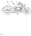
- a control device 100 for a straddle-type vehicle is mounted on a straddle-type vehicle 10.
- the straddle-type vehicle 10 as shown in Fig. 1 , is provided with a clutch lever, an accelerator 12, a front brake lever 13, a throttle valve 14, a rear brake pedal 15, and the like.
- the clutch lever 11, the accelerator 12, the front brake lever 13, the throttle valve 14, and the rear brake pedal 15 are provided with sensors 21 to 25 for detecting their operations, respectively.
- the straddle-type vehicle 10 is provided with a vehicle speed sensor 31 and an engine revolution speed sensor 32.
- the vehicle speed sensor 31 is a sensor for detecting the vehicle speed of the straddle-type vehicle 10 and detects the revolution speed of an axle 33 of a rear wheel 60 in this embodiment.
- the engine revolution speed sensor 32 is a sensor for detecting the revolution speed of an engine 34 (driving source) and detects the revolution speed of a crankshaft of the engine 34 in this embodiment.
- the control device 100 for a straddle-type vehicle is provided with an input part (input means - not shown) to which detection signals detected by the respective sensors 21 to 25, 31, and 32 are inputted.
- the respective sensors 21 to 25, 31, and 32 are connected to the input part so as to communicate. With this, the detection signals detected by the respective sensors 21 to 25, 31, and 32 are sent to the control device 100 for a straddle-type vehicle.
- the control device 100 for a straddle-type vehicle is an electronic processing device and is provided with: an operation means constructed of a MPU or a CPU having an operating function; and a storage means constructed of a non-volatile memory or the like.
- the control device 100 for a straddle-type vehicle is constructed so as to realize a specified function by a previously stored program.
- a throttle valve opening control part 103 output control part/output control means
- a first detection part first detection means
- deceleration processing part deceleration processing means
- the driving source 34 of the straddle-type vehicle is constructed of an engine of an internal combustion engine, and its output is adjusted by the opening of the throttle valve 14. That is, the throttle valve 14 is disposed in an intake passage 36 of the engine 34, and the amount of flow of an air-fuel mixture flowing into the engine 34 is adjusted by the opening of the throttle valve 14.
- This straddle-type vehicle 10 is mounted with an electronic throttle in which the opening of the throttle valve 14 is electronically controlled by a control device.
- a pulley 42 connected to the accelerator 12 by a wire 41 is driven and rotated.
- the pulley 42 is provided with an accelerator position sensor 22 for detecting the amount of rotation of the pulley 42.
- the control device 100 for a straddle-type vehicle detects the amount of rotation of the pulley 42 and the amount of operation of the accelerator 12 on the basis of the detection signal detected by the acceleration position sensor 22.
- the control device 100 for a straddle-type vehicle detects the opening of the throttle valve 14 on the basis of the detection signal detected by the throttle position sensor 24.
- the control device 100 for a straddle-type vehicle computes a target value of the opening (target throttle opening) of the throttle valve 14 along a previously set program on the basis of the detection signal detected by the acceleration position sensor 22 and the information of the vehicle speed sensor 31 and the engine revolution speed sensor 32.
- the control device 100 for a straddle-type vehicle sends an operation signal to an actuator 45 to control the opening of the throttle valve 14 so as to bring the opening of the throttle valve 14 to the target throttle opening.
- the actuator 45 is a motor and rotates the rotary shaft 47 of the throttle valve 14 via a gear 46 to operate the opening of the throttle valve 14.
- the electronic throttle is employed and the opening of the throttle valve 14 is controlled by the control device 100 for a straddle-type vehicle. Further, the control device 100 for a straddle-type vehicle performs a constant-speed running control.
- the constant-speed running control is also referred to as "a cruise control" in some cases.
- the control device 100 for a straddle-type vehicle is provided with a first storage part (first storage means) 101, a throttle valve opening control part (throttle valve opening control means) 103, a first detection part (first detection means) 104, and a deceleration processing part (deceleration processing means) 105.
- the straddle-type vehicle 10 is provided with detection means 40 for detecting that the accelerator 12 is operated in a further closing direction from the totally closed position of the accelerator 12.
- the detection means 40 is fixed to the accelerator 12 and is constructed of pressure detection means (pressure sensor, in this embodiment) for detecting the operation and the operating force of the accelerator 12.
- the pressure sensor 40 performs the function of operation detection means for detecting the accelerator 12 being operated in the further closing direction from the totally closed position of the accelerator 12 and the function of operating force detection means capable of detecting the magnitude of the operating force of the operation.
- the pressure sensor 40 is connected to the control device 100 (input part, not shown) for the straddle-type vehicle, and the detection signal detected by the pressure sensor 40 is sent to the control device 100 for a straddle-type vehicle.
- the detection means for performing a function as the operation detection means and the detection means for performing a function as operating force detection means may be disposed as separate detection means.
- the detection means for performing the function as the operation detection means may be a switch for detecting that the accelerator 12 is operated in the further closing direction from the totally closed position of the accelerator 12.
- the straddle-type vehicle 10 is provided with: a main switch 50 for starting the whole system of the straddle-type vehicle 10; a starting switch 51 of the constant-speed running control; an operation part (operation means) 52 for operating the constant-speed running control, and a display part (display means) 53 for displaying the state of the constant-speed running control.
- the starting switch 51 of the constant-speed running control is a switch for starting the constant-speed running control (cruise control).
- the main switch 50 for starting the whole system of the straddle-type vehicle 10 is turned on or off by turning a key 20 of the straddle-type vehicle 10.
- the straddle-type vehicle 10 is constructed as follows: that is, even if the main switch 50 is on, when the starting switch 51 of the constant-speed running control is off, the constant-speed running control is not performed; and only when the main switch 50 is on and the starting switch 51 of the constant-speed running control is on, the constant-speed running control is performed.
- the operation part 52 is disposed near the accelerator 12 and is provided with three switches 61 to 63.
- a first switch (acceleration/vehicle speed setting switch) 61 functions as an operating switch for activating, or performing, the constant-speed running control and for setting the target vehicle speed of the constant-speed running control. Moreover, when the constant-speed running control is active, the first switch 61 functions as an operating switch for accelerating the target vehicle speed of the constant-speed running control.
- a second switch (deceleration/ resume switch) 62 functions as an operating switch for making the target vehicle speed of the constant-speed running control a target vehicle speed at the immediately preceding constant-speed running control.
- the second switch 62 functions as an operating switch for decelerating the target vehicle speed of the constant-speed running control.
- a third switch (cancel switch) 63 functions as an operating switch for releasing the constant-speed running control and returning the constant-speed running control to a normal running control.
- the above-mentioned respective switches 51, and 61 to 63 are connected to the control device 100 for a straddle-type vehicle, and the input signal is sent to the control device 100 for a straddle-type vehicle.
- the first storage part 101 of the control device 100 for a straddle-type vehicle stores the target vehicle speed of the constant-speed running control.
- the control device 100 for a straddle-type vehicle when the starting switch 51 of the constant-speed running control is off, the control device 100 for a straddle-type vehicle is in a state where the constant-speed running control cannot be performed, and the opening of the throttle valve 14 is controlled on the basis of the operation of the accelerator 12, whereby the vehicle speed is adjusted.
- the starting switch 51 of the constant-speed running control is turned on, there is brought about a state where the constant-speed running control can be performed.
- the target vehicle speed of the constant-speed running control is set to the first storage part 101.
- the constant-speed running control when the constant-speed running control is not active in a state where the starting switch 51 of the constant-speed running control is on, if the first switch 61 is operated, the vehicle speed detected by the vehicle speed sensor 31 when the first switch 61 is operated is stored in the first storage part 101 and becomes the target vehicle speed of the constant-speed running control.
- the constant-speed running control when the constant-speed running control is not active in a state where the starting switch 51 of the constant-speed running control is on, if the second switch 62 is operated, first, the target vehicle speed of the immediately preceding constant-speed running control which is stored in the first storage part 101 is stored separately in the second storage part (second storage means) 102.
- the target vehicle speed of the constant-speed running control stored in the first storage part 101 is gradually updated in such a way that the target vehicle speed of the constant-speed running control becomes the target vehicle speed of the immediately preceding constant-speed running control stored in the second storage part 102, whereby the target vehicle speed of the constant-speed running control stored in the first storage part 101 is gradually brought close to the target vehicle speed of the immediately preceding constant-speed running control stored in the second storage part 102.
- the target vehicle speed of the constant-speed running control stored in the first storage part 101 is finally brought to the final target vehicle speed of the constant-speed running control stored in the second storage part 102.
- the target vehicle speed of the constant-speed running control stored in the first storage part 101 is rewritten to a higher vehicle speed. With this, the target vehicle speed of the constant-speed running control is accelerated and hence the running speed in the constant-speed running control is increased.
- the target vehicle speed of the constant-speed running control is accelerated and hence the running speed in the constant-speed running control is increased.
- the target vehicle speed in the constant-speed running control is decelerated and hence the running speed in the constant-speed running control is decreased.
- the throttle valve opening control part 103 controls the opening of the throttle valve 14 in such a way that the straddle-type vehicle 10 constantly runs at the target vehicle speed stored in the first storage part 101.
- the throttle valve opening control part 103 receives the input of the vehicle speed detected by the vehicle speed sensor 31 and computes a target throttle opening in such a way that a vehicle speed becomes the target vehicle speed. Then, the throttle valve opening control part 103 outputs an operating signal in such a way that the opening of the throttle valve 14 becomes the target throttle opening to operate the actuator 45 to thereby adjust the opening of the throttle valve 14.
- the throttle valve opening control part 103 operates the actuator 45 on the basis of the input from the vehicle speed sensor 31 and the throttle position sensor 24 in such a way that the vehicle speed detected by the vehicle speed sensor 31 is brought to the target vehicle speed stored in the first storage part 101.
- the straddle-type vehicle 10 can be run at a constant speed by the control of the throttle valve opening control part 103. According to this constant-speed running control, even if a rider does not perform a fine adjustment of the accelerator 12, the opening of the throttle valve 14 can be automatically adjusted, so that the load of the rider can be reduced when the drives the vehicle on a highway or the like.
- the constant-speed running control is released. That is, the clutch lever 11, the front brake lever 13, or the rear brake lever 15 can be operated when the rider decelerates the straddle-type vehicle, and when any one of these parts is operated, the constant-speed running control is released.
- the constant-speed running control is released in this manner, for the rider to perform the constant-speed running control again, the rider needs to operate the first switch 61 and the second switch 62.
- the operation part 52 is provided with a switch (deceleration switch: second switch 62) for reducing the target vehicle speed of the constant-speed running control by an easier operation during the constant-speed running control.
- This embodiment is constructed in such a way that during the constant-speed running control, the target vehicle speed of the constant-speed running control can be decreased by an easier operation. That is, this embodiment is constructed in such a way that when the accelerator 12 is operated in a further closing direction from the totally closed position of the accelerator 12 during the constant-speed running control, the target vehicle speed of the constant-speed running control can be decreased.
- the first detection part 104 and the deceleration processing part 105 will be described.
- the first detection part 104 detects that the accelerator 12 is operated in the further closing direction from the totally closed position of the accelerator 12.
- the first detection part 104 receives the detection signal of the pressure sensor 40 (operation detection means) and detects that the accelerator 12 is operated in the further closing direction from the totally closed position of the accelerator 12.
- the control device 100 is started (START) when the main switch 50 for starting the whole system of the straddle-type vehicle 10 is turned on (S1).
- S1 main switch 50 for starting the whole system of the straddle-type vehicle 10 is turned on
- the first detection part 104 always detects whether or not the accelerator 12 is operated in the further closing direction from the totally closed position of the accelerator 12.
- the control device 100 is provided with a determination part (determination means) (S2) for determining whether or not the accelerator 12 is operated in the further closing direction from the totally closed position of the accelerator 12.
- a determination part (determination means) S2 for determining whether or not the accelerator 12 is operated in the further closing direction from the totally closed position of the accelerator 12.
- the determination part (S2) detects whether or not the accelerator 12 is operated in the further closing direction from the totally closed position of the accelerator 12. Then, when it is determined in the determination part (S2) that the accelerator 12 is operated in the further closing direction from the totally closed position of the accelerator 12 (YES), it is further determined (S3) whether or not the constant-speed running control is performed.
- the control device 100 When it is determined in the determination part (S3) that the constant-speed running control is performed (YES), the control device 100 performs a deceleration processing by the deceleration processing part 105 (S4). When it is determined in the determination part (S2) that the constant-speed running control is not performed (NO), the input of the operation (S1) is neglected. In this embodiment, when it is determined in the determination part (S1) that the main switch 50 is turned off, the control flow of the control device 100 is finished (END).
- the deceleration processing part 105 decreases the target vehicle speed stored in the first storage part 101 (S3). That is, when the target vehicle speed stored in the first storage part 101 is decreased, the running speed of the straddle-type vehicle 10 controlled by the constant-speed running control is decreased.
- the deceleration processing part 105 is constructed in such a way as to decrease the target vehicle speed stored in the first storage part 101 during a period of time when the first detection part 104 detects that the accelerator 12 is operated in the further closing direction from the totally closed position of the accelerator 12.
- the deceleration processing part 105 is constructed in such a way as to decrease the target vehicle speed stored in the first storage part 101 at a previously determined rate with respect to time, for example, during a period of time when the first detection part 104 detects the above-mentioned operation.
- the deceleration processing part 105 may change a rate at which the target vehicle speed is decreased according to the magnitude of the operating force.
- the control device 100 for a straddle-type vehicle decreases the target vehicle speed stored in the first storage part 101. In the operation of the straddle-type vehicle 10, it does not happen normally that the accelerator 12 is operated in the further closing direction from the totally closed position of the accelerator 12. By detecting that the accelerator 12 is operated in the further closing direction from the totally closed position of the accelerator 12, the rider's intention of decreasing the vehicle can be detected.
- this control device 100 for a straddle-type vehicle when the rider intends to decelerate the vehicle while the rider drives the vehicle under the constant-speed running control, the rider can operate the accelerator 12 in a state where the rider grips the accelerator 12 as usual, so the control device 100 for a straddle-type vehicle can realize extremely high operability.
- the rider when the rider intends to decelerate the vehicle, the rider unusually returns the accelerator 12 (that is, the accelerator 12 is closed).
- the operating of the accelerator 12 in the further closing direction from the totally closed position of the accelerator 12 can be performed as an extension of the operation of returning the accelerator 12.
- the rider can easily operate the accelerator 12 when the rider intends to decelerates the vehicle.
- the detecting of the rider's intension of decelerating the vehicle during the constant-speed running control by detecting that the rider operates the accelerator 12 in the further closing direction from the totally closed position of the accelerator 12 is one of an optimum method for an operating input method for a straddle-type vehicle.
- this control device 100 for a straddle-type vehicle it is possible to provide a straddle-type vehicle having extremely excellent operability in a straddle-type vehicle for which the constant-speed running control is performed.
- the deceleration processing part 105 decreases the target vehicle speed stored in the first storage part 101 during a period of time when the first detection part 104 detects the above-mentioned operation. That is, while the rider operates the accelerator 12 in the further closing direction from the totally closed position of the accelerator 12, the deceleration processing part 105 decreases the target vehicle speed.
- the deceleration processing part 105 is constructed in such a way as to decrease the target vehicle speed stored in the first storage part 101 at a previously specified deceleration while the first detection part 104 detects the above-mentioned operation.
- the deceleration processing part 105 can decelerate the vehicle by a speed of (a x t) with respect to the period of time t during which the first detection part 104 detects that the accelerator 12 is operated in the further closing direction from the totally closed position of the accelerator 12.
- the deceleration processing part 105 it is possible to make the setting of decreasing the target vehicle speed by 5 km/hr with respect to the operating time of 1 second during which the accelerator 12 is being operated in the further closing direction from the totally closed position of the accelerator 12. Further, in the case of constructing the deceleration processing part 105 in this manner, the rate at which the vehicle speed is decreased with respect to time is constant for the rider, so that the rider can easily take the timing when the rider stops the operation.
- the deceleration processing part 105 can be also constructed in such a way that the rate at which the target vehicle speed is decreased with respect to time is changed according to the magnitude of the operating force for operating the accelerator 12 in the further closing direction from the totally closed position of the accelerator 12.
- the deceleration processing part 105 can be also constructed in such a way that the rate at which the target vehicle speed is decreased with respect to time is increased by increasing the operating force.
- control device 100 for a straddle-type vehicle is provided with: a second detection part (second detection means) 106 for detecting the magnitude of the operating force; and a first setting part 107 for setting the relationship between the magnitude of the operating force detected by the second detection part 106 and the rate at which the target vehicle speed is decreased with respect to time according to the magnitude of the operating force.
- second detection part second detection means
- first setting part 107 for setting the relationship between the magnitude of the operating force detected by the second detection part 106 and the rate at which the target vehicle speed is decreased with respect to time according to the magnitude of the operating force.
- the second detection part 106 is constructed so as to detect the magnitude of the operating force, for example, on the basis of the detection signal of the above-mentioned pressure detection means (operating force detection means) 40.
- the first setting part 107 previously stores the relationship between the magnitude of the operating force detected by the second detection part 106 and the rate at which the target vehicle speed is decreased with respect to time according to the magnitude of the operating force in the storage means of the control device 100 for a straddle-type vehicle. The relationship can be arbitrarily set in advance.
- the second detection part 106 and the first setting part 107 which have been described above, are only examples to embody the construction of the control device 100 for a straddle-type vehicle in such a way that the rate at which the target vehicle speed is decreased with respect to time according to the magnitude of the operating force, and the construction of the control device 100 for a straddle-type vehicle is not limited to this construction.
- control device 100 for a straddle-type vehicle according to one embodiment of the present invention and the straddle-type vehicle according to the one embodiment of the present invention have been described.
- control device 100 for a straddle-type vehicle and the straddle-type vehicle according to the present invention are not limited to the above-mentioned embodiment.
- the deceleration processing part 105 may be constructed in such a way as to decrease the target vehicle speed at a rate that is previously determined with respect to time while the first detection part 104 detects the above-mentioned operation. That is, it is assumed that the rate is b % and that the present target vehicle speed is s. In this case, the target vehicle speed can be decreased by a speed of s (km/h) ⁇ b ⁇ 0.01 ⁇ t(s) with respect to the period of time t(s) during which the first detection part 104 detects that the accelerator 12 is operated in the further closing direction from the totally closed position of the accelerator 12. Specifically, for example, it is assumed that the rate is 5 % and that the present target vehicle speed is 100 km/h.
- the target vehicle speed is decreased by 5 % per the period of time of 1 second during which the accelerator 12 is operated in the further closing direction from the totally closed position of the accelerator 12.
- the rider can easily predict the rate at which the vehicle speed is decreased with respect to time, so that the rider can easily take the timing when the rider stops the operation.
- the deceleration processing part 105 may be constructed in such a way that every time the first detection part 104 detects that the accelerator 12 is operated in the further closing direction from the totally closed position of the accelerator 12, the target vehicle speed stored in the first storage part 101 is decreased.
- the deceleration processing part 105 may be constructed, for example, in such a way that every time the first detection part 104 detects the above-mentioned operation, the target vehicle speed stored in the first storage part 101 is decreased by a previously determined speed. That is, for example, the deceleration processing part 105 can make the setting of decreasing the target vehicle speed by 1 km/h to 2 km/h every time the rider operates the accelerator 12 in the further closing direction from the totally closed position of the accelerator 12.
- the rider can easily adjust the target vehicle speed.
- the deceleration processing part 105 deceases the target vehicle speed every time the rider operates the accelerator 12 in the further closing direction from the totally closed position of the accelerator 12, it suffices that the magnitude of the decrease in the target speed is set to a value in consideration of the operability of the straddle-type vehicle.
- the deceleration processing part 105 may be constructed in the following manner: that is, when the deceleration processing part 105 decreases the target vehicle speed stored in the first storage part 101 every time the first detection part 104 detects the above-mentioned operation, the deceleration processing part 105 changes the degree of decreasing the target vehicle speed according to the magnitude of the operating force of the operation. Specifically, it is also recommendable for the deceleration processing part 105 to store an arbitrary correlation, which is determined between the magnitude of the operating force and the degree of decreasing the target vehicle speed, in a storage part and to set the degree of decreasing the target vehicle speed on the basis of the correlation. Moreover, it suffices to detect the magnitude of the operating force by the second detection part 106.
- the deceleration processing part 105 can be constructed in the following manner: every time the accelerator 12 is operated in the further closing direction from the totally closed position of the accelerator 12, the second detection part 106 detects the magnitude of an operating force; and according to the magnitude of the operating force detected by the second detection part 106, when a large operating force is inputted, the deceleration processing part 105 decreases the target vehicle speed greatly, whereas when a small operating force is inputted, the deceleration processing part 105 decreases the target vehicle speed slightly.
- the magnitude of the operating force it suffices to set one or plural threshold values previously and to divide the magnitude of the operating force stepwise according to the threshold values.
- the arbitrary correlation determined between the magnitude of the operating force and the degree of decreasing the target vehicle speed does not need to be stepwise but may be set in such a way that the degree of decreasing the target vehicle speed is smoothly changed with respect to the magnitude of the operating force.
- the rider can adjust the amount of decrease in the target vehicle speed by the magnitude of the operating force.
- the deceleration processing part 105 may be constructed in such a way that every time the first detection part 104 detects that the accelerator 12 is operated in the further closing direction from the totally closed position of the accelerator 12, the degree of decreasing the target vehicle speed is changed according to the vehicle speed when the operation is detected. That is, for example, it suffices that the deceleration processing part 105 is constructed in the following manner: for example, when the vehicle speed when the operation is detected is 100 km/h, the target vehicle speed of the constant-speed running control is decreased by 10 km/h; and when the vehicle speed when the operation is detected is 50 km/h, the target vehicle speed of the constant-speed running control is decreased by 5 km/h. In this case, it suffices that the correlation between the vehicle speed when the operation is detected and the degree of decreasing the target vehicle speed is previously set and that the degree of decreasing the target vehicle speed is determined on the basis of the set correlation.
- the construction of the deceleration processing part 105 in which every time the first detection part 104 detects that the accelerator 12 is operated in the further closing direction from the totally closed position of the accelerator 12, the degree of decreasing the target vehicle speed is changed according to the vehicle speed when the operation is detected is not limited to the construction in the above-mentioned embodiment.
- the deceleration processing part 105 may be constructed in such a way that a rate at which the target vehicle speed is decreased with respect to time when the accelerator 12 is operated in the closing direction is determined in advance and that the target vehicle speed is decreased by the rate. Specifically, for example, it suffices that the rate at which the target vehicle speed is decreased with respect to time when the operation is detected is determined to be 10 % in advance.
- the target vehicle speed is deceased by 10 km/h and hence the target vehicle speed is brought to 90 km/h.
- the constant-speed running control is performed at a target vehicle speed of 90 km/h
- the target vehicle speed is deceased by 9 km/h and hence the target vehicle speed is brought to 81 km/h.
- the rate at which the target vehicle speed is decreased with respect to time when the accelerator 12 is operated in the closing direction is determined in advance and that, every time the first detection part 104 detects the operation, the target vehicle speed is decreased by the rate according to the target vehicle speed at that time.
- the deceleration processing part 105 may change the degree of decreasing the target vehicle speed according to the opening of the throttle valve when the first detection part 104 detects the above-mentioned operation. That is, in this case, as shown in Fig. 1 , the deceleration processing part 105 may change the degree of decreasing the target vehicle speed on the basis of the information of the opening of the throttle valve 14 detected by the throttle position sensor 24 when the first detection part 104 detects the above-mentioned operation.
- the deceleration processing part 105 may be constructed in the following manner: that is, when the deceleration processing part 105 decreases the target vehicle speed, the deceleration processing part 105 changes the degree of decreasing the target vehicle speed according to a driving torque when the first detection part 104 detects the above-mentioned operation.
- the deceleration processing part 105 may be constructed in such a way as to change the degree of decreasing the target vehicle speed on the basis of the driving torque when the first detection part 104 detects the above-mentioned operation.
- the deceleration processing part 105 may be constructed in such a way as to decrease the target vehicle speed stored in the first storage part 101 every time the first detection part 104 detects the above-mentioned operation. In that case, when the deceleration processing part 105 decreases the target vehicle speed, the deceleration processing part 105 may decrease the target vehicle speed by a previously determined speed. Moreover, the deceleration processing part 105 may be constructed in the following manner: that is, when the deceleration processing part 105 decreases the target vehicle speed, the deceleration processing part 105 changes the degree of decreasing the target vehicle speed according to the magnitude of the operating force.
- the deceleration processing part 105 may be constructed in the following manner: that is, when the deceleration processing part 105 decreases the target vehicle speed, the deceleration processing part 105 changes the degree of decreasing the target vehicle speed according to the vehicle speed when the first detection part 104 detects the above-mentioned operation.
- the pressure detection means 40 fixed to the accelerator 12 has been described as an example of the sensor for detecting the operation and the operating force when the accelerator 12 is operated in the further closing direction from the totally closed position of the accelerator 12, but the position where the pressure detection means 40 is fixed is not limited to the accelerator 12.
- the position where the pressure detection means 40 performing the function is fixed, in the above-mentioned embodiment, as shown in Fig.
- the pulley 42 is fixed to the accelerator 12 by the use of the wire 41, and when the accelerator 12 is turned, the pulley 42 is turned: for this reason, the pulley 42 may have a sensor fixed thereto, the sensor detecting the operation and the operating force when the accelerator 12 is operated in the further closing direction from the totally closed position of the accelerator 12.
- the control device 100 of the straddle-type vehicle can be mounted in various kinds of straddle-type vehicles.
- the straddle-type vehicle in this application includes a two-wheeled motor vehicle such as a motorcycle including a motor-assisted bicycle (motorbike) and a scooter.
- the straddle-type vehicle includes not only the two-wheeled motor vehicle but also a four-wheeled buggy (ATV: All Terrain Vehicle) and a snowmobile.
- the construction in which an internal combustion engine having its output adjusted by the opening of the throttle valve is used as the driving source (engine) has been described as an example.
- the control device 100 for a straddle-type vehicle is provided with the throttle valve opening control part 103 for controlling the opening of the throttle valve 14 as an output control part.
- the driving source is not limited to the internal combustion engine.
- Other driving source such as an electric motor can be employed as the driving source for driving the straddle-type vehicle.
- the output control part 103 has the function of controlling the output of the driving source.
Abstract
Description
- The present invention relates to a control device for a straddle-type vehicle that controls the output of a driving source to drive a straddle-type vehicle and a straddle-type vehicle mounted with the control device.
- Of the control devices for a straddle-type vehicle, a device for controlling constant-speed running is disclosed in Japanese Unexamined Patent Publication No.
2007-113416 2007-137186 -
EP 1 777 150claim 1. - Japanese Unexamined Patent Publication No.
2007-137186 - Moreover, in the same patent document, as a constant-speed running control device for performing constant-speed running control is disclosed a control device that sets a target throttle opening according to an instructed throttle opening instructed through the accelerator by the rider and which controls an actual throttle opening to the target throttle opening. The device is constructed in the following manner: that is, for example, when any one of the instructed throttle opening and the target throttle opening is close to (is in a specified relationship with) an actual throttle opening and when an amount of change per unit time of the instructed throttle opening is compared with a threshold value and the amount of change is the threshold valve or more in a negative direction (a release condition is satisfied), the device switches the constant-speed running control to a throttle target opening control. Thus, this patent document discloses the fact that: with this construction, even if the rider does not return the accelerator to a position where a throttle valve is totally closed, a rider's intension of decreasing the vehicle speed can be detected; and hence an unnecessary decrease in the number of revolution of an engine, that is an unnecessary decrease in the output of the engine, is not caused and a running feeling is not impaired (see, for example, paragraphs 0028 and 0031 in the same patent document) .
- Furthermore, Japanese Unexamined Patent Publication No.
2007-113416 - In the driving of a straddle-type vehicle, a rider operates an accelerator in a state where the rider grips the accelerator while having the air pressure applied to his body, so that when the rider drives the straddle-type vehicle at a constant speed for a long time, the load of air pressure applied to the rider becomes large. A constant-speed running control is control that facilitates the rider's operation of the straddle-type vehicle to decrease the load. The constant-speed running control is used during the driving of a straddle-type vehicle on a road, for example, a highway without a traffic signal and in which the straddle-type vehicle is supposed to be run at a constant speed.
- By the way, in the control device for a straddle-type vehicle disclosed in the above-mentioned Japanese Unexamined Patent Publication No.
2007-137186 2007-113416 - However, an inconvenience is caused by the construction in which when the rider operates the accelerator in the closing direction in the auto-cruise state, the constant-speed running control is released. For example, when the rider drives a vehicle under the constant-speed running control and overtakes another vehicle running at a vehicle speed lower than the target vehicle speed of the constant-speed running control, there is a case where the rider decelerates the vehicle speed so as to meet the speed of the another vehicle and then drives the vehicle after the another vehicle so as to meet the speed of the another vehicle. In this case, when the rider overtakes the another vehicle running at the vehicle speed lower than the target vehicle speed of the constant-speed running control, there is a possibility that the rider will operate the accelerator (throttle grip) in the closing direction like the ordinary operation of the accelerator. In the situation like this, there is a possibility that the constant-speed running control will be released. When the constant-speed running control is unexpectedly released during the constant-speed running control in this manner, the rider needs to again perform the operation of the constant-speed running control. The present inventor thought that such an operation is a troublesome operation for the rider of the straddle-type vehicle.
- A control device for a straddle-type vehicle according to the present invention includes: a first storage means for storing a target vehicle speed for constant-speed running; and a first detection means for detecting that an accelerator is operated in a further closing direction from a totally closed position of the accelerator. Further, the control device for a straddle-type vehicle includes a deceleration processing means that decreases the target vehicle speed stored in the first storage means when the first detection means detects the operation during the constant-speed running control.
- According to this control device for a straddle-type vehicle, when it is detected that the accelerator is operated in the further closing direction from the totally closed position of the accelerator, the target vehicle speed of the constant-speed running is decreased. According to the control device for a straddle-type vehicle, when a rider intends to decrease the vehicle speed during constant-speed running, the rider can perform the operation while gripping the accelerator as usual and the operation of closing the accelerator in the further closing direction from the totally closed position is thought to be an extension of the usual operation of the accelerator at the time of decreasing the vehicle speed, so that the operability of the straddle-type vehicle is extremely excellent. Further, even when the rider operates the accelerator in the closing direction during constant-speed running, it is possible to prevent the constant-speed running control from being unexpectedly released.
- Embodiments of the invention are described hereinafter, by way of example only, with reference to the accompanying drawings.
-
Fig. 1 is a block diagram to show a control device for a straddle-type vehicle according to one embodiment of the present invention -
Fig. 2 is a diagram to show the straddle-type vehicle according to the one embodiment of the present invention -
Fig. 3 is a flow chart to show the control flow of a deceleration processing in a constant-speed running control for the straddle-type vehicle according to the one embodiment of the present invention Detailed Description - Hereinafter, a control device for a straddle-type vehicle according to embodiments of the present invention will be described with reference to the accompanying drawings. In the respective drawings, the members and parts performing the same functions are denoted by the same reference symbols. Moreover, the present invention is not limited to the following embodiment.
- A
control device 100 for a straddle-type vehicle, as shown inFig. 1 andFig. 2 , is mounted on a straddle-type vehicle 10. In this embodiment, the straddle-type vehicle 10, as shown inFig. 1 , is provided with a clutch lever, anaccelerator 12, afront brake lever 13, athrottle valve 14, arear brake pedal 15, and the like. - The clutch lever 11, the
accelerator 12, the front brake lever 13, thethrottle valve 14, and therear brake pedal 15 are provided withsensors 21 to 25 for detecting their operations, respectively. Moreover, the straddle-type vehicle 10 is provided with avehicle speed sensor 31 and an enginerevolution speed sensor 32. Thevehicle speed sensor 31 is a sensor for detecting the vehicle speed of the straddle-type vehicle 10 and detects the revolution speed of anaxle 33 of arear wheel 60 in this embodiment. The enginerevolution speed sensor 32 is a sensor for detecting the revolution speed of an engine 34 (driving source) and detects the revolution speed of a crankshaft of theengine 34 in this embodiment. - The
control device 100 for a straddle-type vehicle is provided with an input part (input means - not shown) to which detection signals detected by therespective sensors 21 to 25, 31, and 32 are inputted. Therespective sensors 21 to 25, 31, and 32 are connected to the input part so as to communicate. With this, the detection signals detected by therespective sensors 21 to 25, 31, and 32 are sent to thecontrol device 100 for a straddle-type vehicle. - In this embodiment, the
control device 100 for a straddle-type vehicle is an electronic processing device and is provided with: an operation means constructed of a MPU or a CPU having an operating function; and a storage means constructed of a non-volatile memory or the like. Thecontrol device 100 for a straddle-type vehicle is constructed so as to realize a specified function by a previously stored program. A throttle valve opening control part 103 (output control part/output control means), a first detection part (first detection means) 104, and a deceleration processing part (deceleration processing means) 105, which will be described later, are embodied by programs, and make thecontrol device 100 for a straddle-type vehicle realize specified functions, respectively. - In this embodiment, the
driving source 34 of the straddle-type vehicle is constructed of an engine of an internal combustion engine, and its output is adjusted by the opening of thethrottle valve 14. That is, thethrottle valve 14 is disposed in anintake passage 36 of theengine 34, and the amount of flow of an air-fuel mixture flowing into theengine 34 is adjusted by the opening of thethrottle valve 14. This straddle-type vehicle 10 is mounted with an electronic throttle in which the opening of thethrottle valve 14 is electronically controlled by a control device. - In this embodiment, when an
accelerator 12 is turned, apulley 42 connected to theaccelerator 12 by awire 41 is driven and rotated. Thepulley 42 is provided with anaccelerator position sensor 22 for detecting the amount of rotation of thepulley 42. Thecontrol device 100 for a straddle-type vehicle detects the amount of rotation of thepulley 42 and the amount of operation of theaccelerator 12 on the basis of the detection signal detected by theacceleration position sensor 22. - The
control device 100 for a straddle-type vehicle detects the opening of thethrottle valve 14 on the basis of the detection signal detected by thethrottle position sensor 24. In this embodiment, thecontrol device 100 for a straddle-type vehicle computes a target value of the opening (target throttle opening) of thethrottle valve 14 along a previously set program on the basis of the detection signal detected by theacceleration position sensor 22 and the information of thevehicle speed sensor 31 and the enginerevolution speed sensor 32. Thecontrol device 100 for a straddle-type vehicle sends an operation signal to anactuator 45 to control the opening of thethrottle valve 14 so as to bring the opening of thethrottle valve 14 to the target throttle opening. In this embodiment, theactuator 45 is a motor and rotates therotary shaft 47 of thethrottle valve 14 via agear 46 to operate the opening of thethrottle valve 14. - In this manner, in this embodiment, the electronic throttle is employed and the opening of the
throttle valve 14 is controlled by thecontrol device 100 for a straddle-type vehicle. Further, thecontrol device 100 for a straddle-type vehicle performs a constant-speed running control. The constant-speed running control is also referred to as "a cruise control" in some cases. - In this embodiment, the
control device 100 for a straddle-type vehicle is provided with a first storage part (first storage means) 101, a throttle valve opening control part (throttle valve opening control means) 103, a first detection part (first detection means) 104, and a deceleration processing part (deceleration processing means) 105. Moreover, in this embodiment, the straddle-type vehicle 10 is provided with detection means 40 for detecting that theaccelerator 12 is operated in a further closing direction from the totally closed position of theaccelerator 12. In this embodiment, the detection means 40 is fixed to theaccelerator 12 and is constructed of pressure detection means (pressure sensor, in this embodiment) for detecting the operation and the operating force of theaccelerator 12. Thepressure sensor 40 performs the function of operation detection means for detecting theaccelerator 12 being operated in the further closing direction from the totally closed position of theaccelerator 12 and the function of operating force detection means capable of detecting the magnitude of the operating force of the operation. Thepressure sensor 40 is connected to the control device 100 (input part, not shown) for the straddle-type vehicle, and the detection signal detected by thepressure sensor 40 is sent to thecontrol device 100 for a straddle-type vehicle. Here, the detection means for performing a function as the operation detection means and the detection means for performing a function as operating force detection means may be disposed as separate detection means. For example, the detection means for performing the function as the operation detection means may be a switch for detecting that theaccelerator 12 is operated in the further closing direction from the totally closed position of theaccelerator 12. - Moreover, in this embodiment, the straddle-
type vehicle 10 is provided with: amain switch 50 for starting the whole system of the straddle-type vehicle 10; a startingswitch 51 of the constant-speed running control; an operation part (operation means) 52 for operating the constant-speed running control, and a display part (display means) 53 for displaying the state of the constant-speed running control. In this embodiment, the startingswitch 51 of the constant-speed running control is a switch for starting the constant-speed running control (cruise control). In this embodiment, themain switch 50 for starting the whole system of the straddle-type vehicle 10 is turned on or off by turning a key 20 of the straddle-type vehicle 10. The straddle-type vehicle 10 is constructed as follows: that is, even if themain switch 50 is on, when the startingswitch 51 of the constant-speed running control is off, the constant-speed running control is not performed; and only when themain switch 50 is on and the startingswitch 51 of the constant-speed running control is on, the constant-speed running control is performed. Theoperation part 52 is disposed near theaccelerator 12 and is provided with threeswitches 61 to 63. - When the constant-speed running control is not active, a first switch (acceleration/vehicle speed setting switch) 61 functions as an operating switch for activating, or performing, the constant-speed running control and for setting the target vehicle speed of the constant-speed running control. Moreover, when the constant-speed running control is active, the
first switch 61 functions as an operating switch for accelerating the target vehicle speed of the constant-speed running control. - When the constant-speed running control is not active, a second switch (deceleration/ resume switch) 62 functions as an operating switch for making the target vehicle speed of the constant-speed running control a target vehicle speed at the immediately preceding constant-speed running control. Moreover, the constant-speed running control is active, the
second switch 62 functions as an operating switch for decelerating the target vehicle speed of the constant-speed running control. - A third switch (cancel switch) 63 functions as an operating switch for releasing the constant-speed running control and returning the constant-speed running control to a normal running control. The above-mentioned
respective switches control device 100 for a straddle-type vehicle, and the input signal is sent to thecontrol device 100 for a straddle-type vehicle. - The
first storage part 101 of thecontrol device 100 for a straddle-type vehicle stores the target vehicle speed of the constant-speed running control. In this embodiment, when the startingswitch 51 of the constant-speed running control is off, thecontrol device 100 for a straddle-type vehicle is in a state where the constant-speed running control cannot be performed, and the opening of thethrottle valve 14 is controlled on the basis of the operation of theaccelerator 12, whereby the vehicle speed is adjusted. When the startingswitch 51 of the constant-speed running control is turned on, there is brought about a state where the constant-speed running control can be performed. - When the
first switch 61 or thesecond switch 62 is operated in a state where the startingswitch 51 of the constant-speed running control is on, the target vehicle speed of the constant-speed running control is set to thefirst storage part 101. - In this embodiment, when the constant-speed running control is not active in a state where the starting
switch 51 of the constant-speed running control is on, if thefirst switch 61 is operated, the vehicle speed detected by thevehicle speed sensor 31 when thefirst switch 61 is operated is stored in thefirst storage part 101 and becomes the target vehicle speed of the constant-speed running control. Moreover, when the constant-speed running control is not active in a state where the startingswitch 51 of the constant-speed running control is on, if thesecond switch 62 is operated, first, the target vehicle speed of the immediately preceding constant-speed running control which is stored in thefirst storage part 101 is stored separately in the second storage part (second storage means) 102. Then, when thesecond switch 62 is operated, the vehicle speed detected by thevehicle speed sensor 31 is stored in thefirst storage part 101 and the constant-speed running control is started. Thereafter, the target vehicle speed of the constant-speed running control stored in thefirst storage part 101 is gradually updated in such a way that the target vehicle speed of the constant-speed running control becomes the target vehicle speed of the immediately preceding constant-speed running control stored in thesecond storage part 102, whereby the target vehicle speed of the constant-speed running control stored in thefirst storage part 101 is gradually brought close to the target vehicle speed of the immediately preceding constant-speed running control stored in thesecond storage part 102. With this, the target vehicle speed of the constant-speed running control stored in thefirst storage part 101 is finally brought to the final target vehicle speed of the constant-speed running control stored in thesecond storage part 102. - Moreover, when the constant-speed running control is active in a state where the starting
switch 51 of the constant-speed running control is on, if thefirst switch 61 is operated, the target vehicle speed of the constant-speed running control stored in thefirst storage part 101 is rewritten to a higher vehicle speed. With this, the target vehicle speed of the constant-speed running control is accelerated and hence the running speed in the constant-speed running control is increased. Moreover, when the constant-speed running control is active, if thesecond switch 62 is operated, the target vehicle speed of the constant-speed running control stored in thefirst storage part 101 is rewritten to a lower vehicle speed. With this, the target vehicle speed in the constant-speed running control is decelerated and hence the running speed in the constant-speed running control is decreased. - Next, the throttle valve
opening control part 103 controls the opening of thethrottle valve 14 in such a way that the straddle-type vehicle 10 constantly runs at the target vehicle speed stored in thefirst storage part 101. The throttle valveopening control part 103 receives the input of the vehicle speed detected by thevehicle speed sensor 31 and computes a target throttle opening in such a way that a vehicle speed becomes the target vehicle speed. Then, the throttle valveopening control part 103 outputs an operating signal in such a way that the opening of thethrottle valve 14 becomes the target throttle opening to operate theactuator 45 to thereby adjust the opening of thethrottle valve 14. - In this embodiment, the throttle valve
opening control part 103 operates theactuator 45 on the basis of the input from thevehicle speed sensor 31 and thethrottle position sensor 24 in such a way that the vehicle speed detected by thevehicle speed sensor 31 is brought to the target vehicle speed stored in thefirst storage part 101. The straddle-type vehicle 10 can be run at a constant speed by the control of the throttle valveopening control part 103. According to this constant-speed running control, even if a rider does not perform a fine adjustment of theaccelerator 12, the opening of thethrottle valve 14 can be automatically adjusted, so that the load of the rider can be reduced when the drives the vehicle on a highway or the like. - Here, in this embodiment, when not only the
third switch 63 of theoperation part 52 is operated but also theclutch lever 11, thefront brake lever 13, or therear brake lever 15 is operated, the constant-speed running control is released. That is, theclutch lever 11, thefront brake lever 13, or therear brake lever 15 can be operated when the rider decelerates the straddle-type vehicle, and when any one of these parts is operated, the constant-speed running control is released. When the constant-speed running control is released in this manner, for the rider to perform the constant-speed running control again, the rider needs to operate thefirst switch 61 and thesecond switch 62. Moreover, as described above, theoperation part 52 is provided with a switch (deceleration switch: second switch 62) for reducing the target vehicle speed of the constant-speed running control by an easier operation during the constant-speed running control. - This embodiment is constructed in such a way that during the constant-speed running control, the target vehicle speed of the constant-speed running control can be decreased by an easier operation. That is, this embodiment is constructed in such a way that when the
accelerator 12 is operated in a further closing direction from the totally closed position of theaccelerator 12 during the constant-speed running control, the target vehicle speed of the constant-speed running control can be decreased. Hereinafter, thefirst detection part 104 and thedeceleration processing part 105 will be described. - Next, the
first detection part 104 detects that theaccelerator 12 is operated in the further closing direction from the totally closed position of theaccelerator 12. In this embodiment, thefirst detection part 104 receives the detection signal of the pressure sensor 40 (operation detection means) and detects that theaccelerator 12 is operated in the further closing direction from the totally closed position of theaccelerator 12. Here, in this embodiment, thecontrol device 100, as shown inFig. 3 , is started (START) when themain switch 50 for starting the whole system of the straddle-type vehicle 10 is turned on (S1). When themain switch 50 is turned on (YES), thefirst detection part 104 always detects whether or not theaccelerator 12 is operated in the further closing direction from the totally closed position of theaccelerator 12. In this embodiment, thecontrol device 100 is provided with a determination part (determination means) (S2) for determining whether or not theaccelerator 12 is operated in the further closing direction from the totally closed position of theaccelerator 12. When themain switch 50 is turned on (YES), the determination part (S2) detects whether or not theaccelerator 12 is operated in the further closing direction from the totally closed position of theaccelerator 12. Then, when it is determined in the determination part (S2) that theaccelerator 12 is operated in the further closing direction from the totally closed position of the accelerator 12 (YES), it is further determined (S3) whether or not the constant-speed running control is performed. When it is determined in the determination part (S3) that the constant-speed running control is performed (YES), thecontrol device 100 performs a deceleration processing by the deceleration processing part 105 (S4). When it is determined in the determination part (S2) that the constant-speed running control is not performed (NO), the input of the operation (S1) is neglected. In this embodiment, when it is determined in the determination part (S1) that themain switch 50 is turned off, the control flow of thecontrol device 100 is finished (END). - Next, when the
first detection part 104 detects that theaccelerator 12 is operated in the further closing direction from the totally closed position of the accelerator 12 (S1), thedeceleration processing part 105 decreases the target vehicle speed stored in the first storage part 101 (S3). That is, when the target vehicle speed stored in thefirst storage part 101 is decreased, the running speed of the straddle-type vehicle 10 controlled by the constant-speed running control is decreased. - In this embodiment, the
deceleration processing part 105 is constructed in such a way as to decrease the target vehicle speed stored in thefirst storage part 101 during a period of time when thefirst detection part 104 detects that theaccelerator 12 is operated in the further closing direction from the totally closed position of theaccelerator 12. In this case, it suffices that thedeceleration processing part 105 is constructed in such a way as to decrease the target vehicle speed stored in thefirst storage part 101 at a previously determined rate with respect to time, for example, during a period of time when thefirst detection part 104 detects the above-mentioned operation. Here, thedeceleration processing part 105 may change a rate at which the target vehicle speed is decreased according to the magnitude of the operating force. - In this embodiment, as described above, when the
first detection part 104 detects that theaccelerator 12 is operated in the further closing direction from the totally closed position of theaccelerator 12 during the constant-speed running control, thecontrol device 100 for a straddle-type vehicle decreases the target vehicle speed stored in thefirst storage part 101. In the operation of the straddle-type vehicle 10, it does not happen normally that theaccelerator 12 is operated in the further closing direction from the totally closed position of theaccelerator 12. By detecting that theaccelerator 12 is operated in the further closing direction from the totally closed position of theaccelerator 12, the rider's intention of decreasing the vehicle can be detected. Moreover, according to thiscontrol device 100 for a straddle-type vehicle, when the rider intends to decelerate the vehicle while the rider drives the vehicle under the constant-speed running control, the rider can operate theaccelerator 12 in a state where the rider grips theaccelerator 12 as usual, so thecontrol device 100 for a straddle-type vehicle can realize extremely high operability. - Further, in this case, when the rider intends to decelerate the vehicle, the rider unusually returns the accelerator 12 (that is, the
accelerator 12 is closed). The operating of theaccelerator 12 in the further closing direction from the totally closed position of theaccelerator 12 can be performed as an extension of the operation of returning theaccelerator 12. Moreover, because the operating of theaccelerator 12 in the further closing direction from the totally closed position of theaccelerator 12 can be performed as the extension of the operation of returning theaccelerator 12, the rider can easily operate theaccelerator 12 when the rider intends to decelerates the vehicle. In other words, the detecting of the rider's intension of decelerating the vehicle during the constant-speed running control by detecting that the rider operates theaccelerator 12 in the further closing direction from the totally closed position of theaccelerator 12 is one of an optimum method for an operating input method for a straddle-type vehicle. According to thiscontrol device 100 for a straddle-type vehicle, it is possible to provide a straddle-type vehicle having extremely excellent operability in a straddle-type vehicle for which the constant-speed running control is performed. - Still further, in this embodiment, the
deceleration processing part 105 decreases the target vehicle speed stored in thefirst storage part 101 during a period of time when thefirst detection part 104 detects the above-mentioned operation. That is, while the rider operates theaccelerator 12 in the further closing direction from the totally closed position of theaccelerator 12, thedeceleration processing part 105 decreases the target vehicle speed. With this, when the rider operates theaccelerator 12 in the further closing direction from the totally closed position of theaccelerator 12 to decrease the target vehicle speed of the constant-speed running control to thereby bring the vehicle speed of the straddle-type vehicle to a suitable value, if the rider stops the operation, the constant-speed running control is performed at the vehicle speed and hence the rider can easily adjust the vehicle speed of the constant-speed running control. - In this embodiment, the
deceleration processing part 105 is constructed in such a way as to decrease the target vehicle speed stored in thefirst storage part 101 at a previously specified deceleration while thefirst detection part 104 detects the above-mentioned operation. For example, when it is assumed that the deceleration is a, thedeceleration processing part 105 can decelerate the vehicle by a speed of (a x t) with respect to the period of time t during which thefirst detection part 104 detects that theaccelerator 12 is operated in the further closing direction from the totally closed position of theaccelerator 12. For example, it is possible to make the setting of decreasing the target vehicle speed by 5 km/hr with respect to the operating time of 1 second during which theaccelerator 12 is being operated in the further closing direction from the totally closed position of theaccelerator 12. Further, in the case of constructing thedeceleration processing part 105 in this manner, the rate at which the vehicle speed is decreased with respect to time is constant for the rider, so that the rider can easily take the timing when the rider stops the operation. - Furthermore, the
deceleration processing part 105 can be also constructed in such a way that the rate at which the target vehicle speed is decreased with respect to time is changed according to the magnitude of the operating force for operating theaccelerator 12 in the further closing direction from the totally closed position of theaccelerator 12. For example, thedeceleration processing part 105 can be also constructed in such a way that the rate at which the target vehicle speed is decreased with respect to time is increased by increasing the operating force. With this, when the rider wants to decelerate the vehicle more quickly, it suffices that the rider applies a large operating force to theaccelerator 12, whereas when the rider wants to decelerate the vehicle more slowly, it suffices that the rider applies a small operating force to theaccelerator 12, which results in improving the operability of decelerating the vehicle. With this, the rider can easily decelerate the vehicle more smoothly and in the manner as the rider intends. Thus, the rider can be provided with an excellent operability. - In this regard, in this case, it suffices that the
control device 100 for a straddle-type vehicle is provided with: a second detection part (second detection means) 106 for detecting the magnitude of the operating force; and afirst setting part 107 for setting the relationship between the magnitude of the operating force detected by thesecond detection part 106 and the rate at which the target vehicle speed is decreased with respect to time according to the magnitude of the operating force. - It suffices that the
second detection part 106 is constructed so as to detect the magnitude of the operating force, for example, on the basis of the detection signal of the above-mentioned pressure detection means (operating force detection means) 40. Moreover, it suffices that thefirst setting part 107 previously stores the relationship between the magnitude of the operating force detected by thesecond detection part 106 and the rate at which the target vehicle speed is decreased with respect to time according to the magnitude of the operating force in the storage means of thecontrol device 100 for a straddle-type vehicle. The relationship can be arbitrarily set in advance. It suffices to change the rate at which the target vehicle speed is decreased with respect to time according to the magnitude of the operating force detected by thesecond detection part 106 on the basis of the relationship between the magnitude of the operating force detected by thesecond detection part 106 and the rate at which the target vehicle speed is decreased with respect to time according to the magnitude of the operating force, the relationship being previously set by thefirst setting part 107. Thesecond detection part 106 and thefirst setting part 107, which have been described above, are only examples to embody the construction of thecontrol device 100 for a straddle-type vehicle in such a way that the rate at which the target vehicle speed is decreased with respect to time according to the magnitude of the operating force, and the construction of thecontrol device 100 for a straddle-type vehicle is not limited to this construction. - Up to this point, the
control device 100 for a straddle-type vehicle according to one embodiment of the present invention and the straddle-type vehicle according to the one embodiment of the present invention have been described. However, thecontrol device 100 for a straddle-type vehicle and the straddle-type vehicle according to the present invention are not limited to the above-mentioned embodiment. - For example, the
deceleration processing part 105 may be constructed in such a way as to decrease the target vehicle speed at a rate that is previously determined with respect to time while thefirst detection part 104 detects the above-mentioned operation. That is, it is assumed that the rate is b % and that the present target vehicle speed is s. In this case, the target vehicle speed can be decreased by a speed of s (km/h) × b × 0.01 × t(s) with respect to the period of time t(s) during which thefirst detection part 104 detects that theaccelerator 12 is operated in the further closing direction from the totally closed position of theaccelerator 12. Specifically, for example, it is assumed that the rate is 5 % and that the present target vehicle speed is 100 km/h. In this case, the target vehicle speed is decreased by 5 % per the period of time of 1 second during which theaccelerator 12 is operated in the further closing direction from the totally closed position of theaccelerator 12. In other words, the following control can be realized: in the first period of time of 1 second, the target vehicle speed is decreased by a speed of 5 km/h (= 100 (km/h) x 5 x 0.01 x 1(s)), thereby being decreased to 95 km/h; then, in the next period of time of 1 second, the target vehicle speed is decreased by a speed of 4.75 km/h (= 95 (km/h) x 5 x 0.01 x 1(s)), thereby being decreased to 90.25 km/h; and thereafter, ditto. Even in this construction, the rider can easily predict the rate at which the vehicle speed is decreased with respect to time, so that the rider can easily take the timing when the rider stops the operation. - Moreover, the
deceleration processing part 105 may be constructed in such a way that every time thefirst detection part 104 detects that theaccelerator 12 is operated in the further closing direction from the totally closed position of theaccelerator 12, the target vehicle speed stored in thefirst storage part 101 is decreased. In this case, thedeceleration processing part 105 may be constructed, for example, in such a way that every time thefirst detection part 104 detects the above-mentioned operation, the target vehicle speed stored in thefirst storage part 101 is decreased by a previously determined speed. That is, for example, thedeceleration processing part 105 can make the setting of decreasing the target vehicle speed by 1 km/h to 2 km/h every time the rider operates theaccelerator 12 in the further closing direction from the totally closed position of theaccelerator 12. Also in this case, the rider can easily adjust the target vehicle speed. In this regard, as for how much thedeceleration processing part 105 deceases the target vehicle speed every time the rider operates theaccelerator 12 in the further closing direction from the totally closed position of theaccelerator 12, it suffices that the magnitude of the decrease in the target speed is set to a value in consideration of the operability of the straddle-type vehicle. - Still further, for example, the
deceleration processing part 105 may be constructed in the following manner: that is, when thedeceleration processing part 105 decreases the target vehicle speed stored in thefirst storage part 101 every time thefirst detection part 104 detects the above-mentioned operation, thedeceleration processing part 105 changes the degree of decreasing the target vehicle speed according to the magnitude of the operating force of the operation. Specifically, it is also recommendable for thedeceleration processing part 105 to store an arbitrary correlation, which is determined between the magnitude of the operating force and the degree of decreasing the target vehicle speed, in a storage part and to set the degree of decreasing the target vehicle speed on the basis of the correlation. Moreover, it suffices to detect the magnitude of the operating force by thesecond detection part 106. For example, thedeceleration processing part 105 can be constructed in the following manner: every time theaccelerator 12 is operated in the further closing direction from the totally closed position of theaccelerator 12, thesecond detection part 106 detects the magnitude of an operating force; and according to the magnitude of the operating force detected by thesecond detection part 106, when a large operating force is inputted, thedeceleration processing part 105 decreases the target vehicle speed greatly, whereas when a small operating force is inputted, thedeceleration processing part 105 decreases the target vehicle speed slightly. In this case, for example, as for the magnitude of the operating force, it suffices to set one or plural threshold values previously and to divide the magnitude of the operating force stepwise according to the threshold values. It suffices to previously set the magnitude of the operating force and the amount of decease in the target vehicle speed stepwise in such a way that when the operating force is large, the amount of decrease in the target vehicle speed becomes large. Further, the arbitrary correlation determined between the magnitude of the operating force and the degree of decreasing the target vehicle speed does not need to be stepwise but may be set in such a way that the degree of decreasing the target vehicle speed is smoothly changed with respect to the magnitude of the operating force. In this manner, when thedeceleration processing part 105 is constructed in such a way that the degree of decreasing the target vehicle speed is changed according to the magnitude of the operating force of the operation, the rider can adjust the amount of decrease in the target vehicle speed by the magnitude of the operating force. Thus, this can improve the operability of the straddle-type vehicle. - Still further, the
deceleration processing part 105 may be constructed in such a way that every time thefirst detection part 104 detects that theaccelerator 12 is operated in the further closing direction from the totally closed position of theaccelerator 12, the degree of decreasing the target vehicle speed is changed according to the vehicle speed when the operation is detected. That is, for example, it suffices that thedeceleration processing part 105 is constructed in the following manner: for example, when the vehicle speed when the operation is detected is 100 km/h, the target vehicle speed of the constant-speed running control is decreased by 10 km/h; and when the vehicle speed when the operation is detected is 50 km/h, the target vehicle speed of the constant-speed running control is decreased by 5 km/h. In this case, it suffices that the correlation between the vehicle speed when the operation is detected and the degree of decreasing the target vehicle speed is previously set and that the degree of decreasing the target vehicle speed is determined on the basis of the set correlation. - Still further, the construction of the
deceleration processing part 105 in which every time thefirst detection part 104 detects that theaccelerator 12 is operated in the further closing direction from the totally closed position of theaccelerator 12, the degree of decreasing the target vehicle speed is changed according to the vehicle speed when the operation is detected is not limited to the construction in the above-mentioned embodiment. As another embodiment, for example, thedeceleration processing part 105 may be constructed in such a way that a rate at which the target vehicle speed is decreased with respect to time when theaccelerator 12 is operated in the closing direction is determined in advance and that the target vehicle speed is decreased by the rate. Specifically, for example, it suffices that the rate at which the target vehicle speed is decreased with respect to time when the operation is detected is determined to be 10 % in advance. In this case, in the case where the constant-speed running control is performed at a target vehicle speed of 100 km/h, when thefirst detection part 104 detects the operation, the target vehicle speed is deceased by 10 km/h and hence the target vehicle speed is brought to 90 km/h. Further, in the case where the constant-speed running control is performed at a target vehicle speed of 90 km/h, when thefirst detection part 104 detects the operation, the target vehicle speed is deceased by 9 km/h and hence the target vehicle speed is brought to 81 km/h. In this manner, for example, it is also recommendable that the rate at which the target vehicle speed is decreased with respect to time when theaccelerator 12 is operated in the closing direction is determined in advance and that, every time thefirst detection part 104 detects the operation, the target vehicle speed is decreased by the rate according to the target vehicle speed at that time. - Moreover, when the
deceleration processing part 105 decreases the target vehicle speed, thedeceleration processing part 105 may change the degree of decreasing the target vehicle speed according to the opening of the throttle valve when thefirst detection part 104 detects the above-mentioned operation. That is, in this case, as shown inFig. 1 , thedeceleration processing part 105 may change the degree of decreasing the target vehicle speed on the basis of the information of the opening of thethrottle valve 14 detected by thethrottle position sensor 24 when thefirst detection part 104 detects the above-mentioned operation. Further, thedeceleration processing part 105 may be constructed in the following manner: that is, when thedeceleration processing part 105 decreases the target vehicle speed, thedeceleration processing part 105 changes the degree of decreasing the target vehicle speed according to a driving torque when thefirst detection part 104 detects the above-mentioned operation. That is, in this case, as for the driving torque, although not shown, the driving torque of the crankshaft of the engine of the straddle-type vehicle, the main shaft after a first deceleration, or the driving shaft of the rear wheel is detected, and thedeceleration processing part 105 may be constructed in such a way as to change the degree of decreasing the target vehicle speed on the basis of the driving torque when thefirst detection part 104 detects the above-mentioned operation. - In this manner, the
deceleration processing part 105 may be constructed in such a way as to decrease the target vehicle speed stored in thefirst storage part 101 every time thefirst detection part 104 detects the above-mentioned operation. In that case, when thedeceleration processing part 105 decreases the target vehicle speed, thedeceleration processing part 105 may decrease the target vehicle speed by a previously determined speed. Moreover, thedeceleration processing part 105 may be constructed in the following manner: that is, when thedeceleration processing part 105 decreases the target vehicle speed, thedeceleration processing part 105 changes the degree of decreasing the target vehicle speed according to the magnitude of the operating force. Further, thedeceleration processing part 105 may be constructed in the following manner: that is, when thedeceleration processing part 105 decreases the target vehicle speed, thedeceleration processing part 105 changes the degree of decreasing the target vehicle speed according to the vehicle speed when thefirst detection part 104 detects the above-mentioned operation. - Further, in the above-mentioned embodiment, the pressure detection means 40 fixed to the
accelerator 12 has been described as an example of the sensor for detecting the operation and the operating force when theaccelerator 12 is operated in the further closing direction from the totally closed position of theaccelerator 12, but the position where the pressure detection means 40 is fixed is not limited to theaccelerator 12. For example, as for the position where the pressure detection means 40 performing the function is fixed, in the above-mentioned embodiment, as shown inFig. 1 , thepulley 42 is fixed to theaccelerator 12 by the use of thewire 41, and when theaccelerator 12 is turned, thepulley 42 is turned: for this reason, thepulley 42 may have a sensor fixed thereto, the sensor detecting the operation and the operating force when theaccelerator 12 is operated in the further closing direction from the totally closed position of theaccelerator 12. - The
control device 100 of the straddle-type vehicle can be mounted in various kinds of straddle-type vehicles. Here, "the straddle-type vehicle" in this application includes a two-wheeled motor vehicle such as a motorcycle including a motor-assisted bicycle (motorbike) and a scooter. Moreover, "the straddle-type vehicle" includes not only the two-wheeled motor vehicle but also a four-wheeled buggy (ATV: All Terrain Vehicle) and a snowmobile. - Furthermore, in the above-mentioned embodiment, the construction in which an internal combustion engine having its output adjusted by the opening of the throttle valve is used as the driving source (engine) has been described as an example. In this case, the
control device 100 for a straddle-type vehicle is provided with the throttle valveopening control part 103 for controlling the opening of thethrottle valve 14 as an output control part. Here, in the straddle-type vehicle according to the present invention, the driving source is not limited to the internal combustion engine. Other driving source such as an electric motor can be employed as the driving source for driving the straddle-type vehicle. In this case, it suffices that theoutput control part 103 has the function of controlling the output of the driving source. -
- 10-
- straddle-type vehicle
- 11-
- clutch lever
- 12-
- accelerator
- 13-
- front brake lever
- 14-
- throttle valve
- 15-
- rear brake pedal
- 22-
- accelerator position sensor
- 24-
- throttle position sensor
- 31-
- vehicle speed sensor
- 32-
- engine revolution speed sensor
- 33-
- axle of rear wheel
- 34-
- engine (driving source)
- 36-
- intake passage
- 40-
- detection means for detecting operation
- 41-
- wire
- 42-
- pulley
- 45-
- actuator
- 46-
- gear
- 47-
- rotary shaft of throttle valve
- 50-
- main switch for starting whole system of straddle-type vehicle
- 51-
- switch for starting constant-speed running control
- 52-
- operation part
- 53-
- display part
- 61-
- first switch (acceleration/ vehicle speed setting switch)
- 62-
- second switch (deceleration/ resume switch)
- 63-
- third switch (cancel switch)
- 100-
- control device
- 101-
- first storage part
- 102-
- second storage part
- 103-
- throttle valve opening control part (output control part)
- 104-
- first detection part
- 105-
- deceleration processing part
- 106-
- second detection part
- 107-
- first setting part
Claims (16)
- A control device for a straddle-type vehicle that performs constant-speed running control for a straddle-type vehicle, the control device comprising:a first storage means for storing a target vehicle speed of constant-speed running;a first detection means for detecting that an accelerator is operated in a further closing direction from a totally closed position of the accelerator;characterized by a deceleration processing means that decreases the target vehicle speed stored in the first storage means when the first detection means detects the operation during constant-speed running control.
- The control device for a straddle-type vehicle as claimed in claim 1, wherein the deceleration processing means decreases the target vehicle speed stored in the first storage means while the first detection means detects the operation.
- The control device for a straddle-type vehicle as claimed in claim 2, wherein the deceleration processing means decreases the target vehicle speed stored in the first storage means at a rate previously determined with respect to time while the first detection means detects the operation.
- The control device for a straddle-type vehicle as claimed in claim 3, wherein the deceleration processing means changes the rate according to a magnitude of an operating force of the operation.
- The control device for a straddle-type vehicle as claimed in claim 4, comprising:a second detection means for detecting a magnitude of the operating force of the operation; anda first setting means for setting a relationship between the magnitude of the operating force of the operation detected by the second detection means and the rate,wherein the deceleration processing means changes the rate according to a magnitude of the operating force of the operation detected by the second detection means on the basis of the relationship between the magnitude of the operating force of the operation and the rate, the relationship being set by the first setting means.
- The control device for a straddle-type vehicle as claimed in claim 1,
wherein the deceleration processing means decreases the target vehicle speed stored in the first storage means at an deceleration previously determined while the first detection means detects the operation. - The control device for a straddle-type vehicle as claimed in claim 1,
wherein the deceleration processing means decreases the target vehicle speed stored in the first storage means every time the first detection means detects the operation. - The control device for a straddle-type vehicle as claimed in claim 7,
wherein when the deceleration processing means decreases the target vehicle speed, the deceleration processing means decreases the target vehicle speed by a previously determined speed. - The control device for a straddle-type vehicle as claimed in claim 7,
wherein when the deceleration processing means decreases the target vehicle speed, the deceleration processing means changes a degree of decreasing the target vehicle speed according to a magnitude of an operating force of the operation. - The control device for a straddle-type vehicle as claimed in claim 7,
wherein when the deceleration processing means decreases the target vehicle speed, the deceleration processing means changes a degree of decreasing the target vehicle speed according to a vehicle speed when the first detection means detects the operation. - The control device for a straddle-type vehicle as claimed in claim 7,
wherein when the deceleration processing means decreases the target vehicle speed, the deceleration processing means changes a degree of decreasing the target vehicle speed according to an opening of a throttle valve when the first detection means detects the operation. - The control device for a straddle-type vehicle as claimed in claim 7,
wherein when the deceleration processing means decreases the target vehicle speed, the deceleration processing means changes a degree of decreasing the target vehicle speed according to a driving torque when the first detection means detects the operation. - A straddle-type vehicle mounted with the control device for a straddle-type vehicle as claimed in any one of claims 1 to 12.
- The straddle-type vehicle as claimed in claim 13, comprising
operation detection means for detecting that an accelerator is operated in a further closing direction from a totally closed position of the accelerator, wherein the first detection means of the control device detects the operation on the basis of a detection signal detected by the operation detection means. - A straddle-type vehicle mounted with the control device for a straddle-type vehicle as claimed in claim 5 or claim 9, comprising
operation detection means for detecting a magnitude of an operating force when an accelerator is operated in a further closing direction from a totally closed position of the accelerator,
wherein the second detection means detects a magnitude of the operating force on the basis of a detection signal detected by the operation detection means. - The straddle-type vehicle as claimed in claim 13,
wherein the straddle-type vehicle is provided with an internal combustion engine as a driving source and is provided with a mechanism for adjusting an output of the internal combustion engine by an opening of a throttle valve, and
wherein the control device for a straddle-type vehicle controls the opening of the throttle valve in such a way that the straddle-type vehicle runs constantly at a target vehicle speed stored in the first storage means during the constant-speed running control.
Applications Claiming Priority (1)
| Application Number | Priority Date | Filing Date | Title |
|---|---|---|---|
| JP2007335094A JP2009154713A (en) | 2007-12-26 | 2007-12-26 | Control device for saddle-ride type vehicle and saddle-ride type vehicle |
Publications (3)
| Publication Number | Publication Date |
|---|---|
| EP2075152A2 EP2075152A2 (en) | 2009-07-01 |
| EP2075152A3 EP2075152A3 (en) | 2010-01-13 |
| EP2075152B1 true EP2075152B1 (en) | 2011-05-11 |
Family
ID=40466941
Family Applications (1)
| Application Number | Title | Priority Date | Filing Date |
|---|---|---|---|
| EP08254067A Active EP2075152B1 (en) | 2007-12-26 | 2008-12-18 | Control device for straddle-type vehicle and straddle-type vehicle |
Country Status (5)
| Country | Link |
|---|---|
| US (1) | US20090171546A1 (en) |
| EP (1) | EP2075152B1 (en) |
| JP (1) | JP2009154713A (en) |
| AT (1) | ATE508899T1 (en) |
| ES (1) | ES2363568T3 (en) |
Families Citing this family (18)
| Publication number | Priority date | Publication date | Assignee | Title |
|---|---|---|---|---|
| JP5048621B2 (en) * | 2008-09-25 | 2012-10-17 | 株式会社ケーヒン | Control device for vehicle engine |
| JP2011088581A (en) * | 2009-10-26 | 2011-05-06 | Yamaha Motor Co Ltd | Snowmobile |
| MX2012014069A (en) | 2010-06-03 | 2013-01-24 | Polaris Inc | Electronic throttle control. |
| WO2012042528A2 (en) * | 2010-09-28 | 2012-04-05 | Tvs Motor Company Limited | A vehicle speed control system |
| JP6178327B2 (en) * | 2012-10-12 | 2017-08-09 | ヤマハ発動機株式会社 | Accelerator grip assembly and vehicle equipped with accelerator grip assembly |
| EP2949523B1 (en) * | 2014-05-27 | 2018-04-25 | Jörg Beutler | Weight-independent safety brake |
| CN106573661B (en) * | 2014-06-04 | 2019-03-22 | 株式会社F.C.C. | Saddle-ride type vehicle |
| JP6410509B2 (en) * | 2014-08-04 | 2018-10-24 | 株式会社エフ・シー・シー | Saddle riding |
| EP3212484A2 (en) | 2014-10-31 | 2017-09-06 | Polaris Industries Inc. | System and method for controlling a vehicle |
| JP6304692B2 (en) * | 2015-03-27 | 2018-04-04 | 本田技研工業株式会社 | Saddle riding |
| US10118667B2 (en) | 2015-05-28 | 2018-11-06 | Shimano Inc. | Bicycle motor control system |
| US10053184B2 (en) * | 2015-05-28 | 2018-08-21 | Shimano Inc. | Bicycle motor control system |
| JP6649501B2 (en) * | 2016-09-27 | 2020-02-19 | 本田技研工業株式会社 | vehicle |
| CA3043481C (en) | 2016-11-18 | 2022-07-26 | Polaris Industries Inc. | Vehicle having adjustable suspension |
| US10406884B2 (en) | 2017-06-09 | 2019-09-10 | Polaris Industries Inc. | Adjustable vehicle suspension system |
| JP7118134B2 (en) | 2018-03-29 | 2022-08-15 | 本田技研工業株式会社 | straddle-type vehicle |
| DE112021003108T5 (en) * | 2020-06-03 | 2023-04-27 | Yamaha Hatsudoki Kabushiki Kaisha | TILT VEHICLE |
| CA3182725A1 (en) | 2020-07-17 | 2022-01-20 | Polaris Industries Inc. | Adjustable suspensions and vehicle operation for off-road recreational vehicles |
Family Cites Families (14)
| Publication number | Priority date | Publication date | Assignee | Title |
|---|---|---|---|---|
| JPS6050035A (en) * | 1983-08-31 | 1985-03-19 | Yamaha Motor Co Ltd | Automatic speed governor of motorcycle |
| JPH0825407B2 (en) * | 1986-08-19 | 1996-03-13 | アイシン精機株式会社 | Speed control device |
| US4969531A (en) * | 1988-04-20 | 1990-11-13 | Honda Giken Kogyo Kabushiki Kaisha | Constant vehicle speed operation control method and device |
| US5532929A (en) * | 1992-12-16 | 1996-07-02 | Toyota Jidosha Kabushiki Kaisha | Apparatus for controlling vehicle driving power |
| US6135227A (en) * | 1997-10-22 | 2000-10-24 | G-Zero Technologies, Llc | Motorcycle cruise control |
| US6250173B1 (en) * | 1998-12-21 | 2001-06-26 | Fred M. Huston | Cruise control for a motorcycle |
| US6276230B1 (en) * | 1999-05-11 | 2001-08-21 | Cts Corporation | Handle bar throttle controller |
| JP4218817B2 (en) * | 2000-03-03 | 2009-02-04 | 本田技研工業株式会社 | Constant vehicle speed maintaining device for motorcycles |
| US6820710B2 (en) * | 2001-09-12 | 2004-11-23 | Bryan W. Fechner | Motorcycle cruise control system with brake release |
| US6978694B2 (en) * | 2002-12-06 | 2005-12-27 | Magneti Marelli Powertrain U.S.A., Inc. | Handlebar throttle controller with hysteresis |
| US7769520B2 (en) * | 2003-10-27 | 2010-08-03 | Ford Global Technologies, Llc | Tractive force map |
| JP4732119B2 (en) | 2005-10-18 | 2011-07-27 | 本田技研工業株式会社 | Intake control device for saddle-ride type vehicles |
| JP4414389B2 (en) * | 2005-10-18 | 2010-02-10 | 本田技研工業株式会社 | Saddle riding |
| JP4037885B2 (en) | 2005-11-16 | 2008-01-23 | 株式会社ケーヒン | Constant speed travel control device for saddle riding type vehicle |
-
2007
- 2007-12-26 JP JP2007335094A patent/JP2009154713A/en not_active Withdrawn
-
2008
- 2008-12-18 AT AT08254067T patent/ATE508899T1/en not_active IP Right Cessation
- 2008-12-18 ES ES08254067T patent/ES2363568T3/en active Active
- 2008-12-18 EP EP08254067A patent/EP2075152B1/en active Active
- 2008-12-22 US US12/341,686 patent/US20090171546A1/en not_active Abandoned
Also Published As
| Publication number | Publication date |
|---|---|
| JP2009154713A (en) | 2009-07-16 |
| ATE508899T1 (en) | 2011-05-15 |
| EP2075152A3 (en) | 2010-01-13 |
| US20090171546A1 (en) | 2009-07-02 |
| EP2075152A2 (en) | 2009-07-01 |
| ES2363568T3 (en) | 2011-08-09 |
Similar Documents
| Publication | Publication Date | Title |
|---|---|---|
| EP2075152B1 (en) | Control device for straddle-type vehicle and straddle-type vehicle | |
| EP1722084B1 (en) | Throttle control device and method | |
| US7753156B2 (en) | Control system and vehicle including the same | |
| US8226527B2 (en) | Straddle type vehicle and speed change control unit of continuously variable transmission | |
| US7162353B2 (en) | Automotive control apparatus and method | |
| US10336329B2 (en) | Saddled vehicle | |
| US8442731B2 (en) | Control and transmission of straddle type vehicle, and the same | |
| JP5481933B2 (en) | Accelerator pedal force control device | |
| JPH0937407A (en) | Controller for regenerative braking | |
| WO2011092957A1 (en) | Device to control force required to depress accelerator pedal | |
| JP2007276542A (en) | Traveling control device for vehicle | |
| JPH0723070B2 (en) | Vehicle anti-slip device | |
| JP2009280098A (en) | Travel control device for vehicle | |
| EP3974274A2 (en) | Motorcycle | |
| JP5947800B2 (en) | Control device for control of engine power | |
| JP3951546B2 (en) | Accelerator pedal device for vehicle | |
| JP3204840B2 (en) | Constant speed cruise control device for vehicles | |
| JPH09142270A (en) | Braking force retaining device for vehicle | |
| JP2550152B2 (en) | Throttle control device in vehicle | |
| JP3562207B2 (en) | Vehicle driving force control device | |
| JP2822039B2 (en) | Constant speed cruise control device for automobile | |
| JPH07139383A (en) | Throttle control device | |
| JPH1111178A (en) | Constant speed travel device for vehicle | |
| JPH11101141A (en) | Device for controlling drive power for vehicle | |
| JPH08158904A (en) | Driving force control device for vehicle |
Legal Events
| Date | Code | Title | Description |
|---|---|---|---|
| PUAI | Public reference made under article 153(3) epc to a published international application that has entered the european phase |
Free format text: ORIGINAL CODE: 0009012 |
|
| AK | Designated contracting states |
Kind code of ref document: A2 Designated state(s): AT BE BG CH CY CZ DE DK EE ES FI FR GB GR HR HU IE IS IT LI LT LU LV MC MT NL NO PL PT RO SE SI SK TR |
|
| AX | Request for extension of the european patent |
Extension state: AL BA MK RS |
|
| PUAL | Search report despatched |
Free format text: ORIGINAL CODE: 0009013 |
|
| AK | Designated contracting states |
Kind code of ref document: A3 Designated state(s): AT BE BG CH CY CZ DE DK EE ES FI FR GB GR HR HU IE IS IT LI LT LU LV MC MT NL NO PL PT RO SE SI SK TR |
|
| AX | Request for extension of the european patent |
Extension state: AL BA MK RS |
|
| RIC1 | Information provided on ipc code assigned before grant |
Ipc: B60K 31/00 20060101AFI20090331BHEP Ipc: B62K 23/04 20060101ALI20091210BHEP |
|
| 17P | Request for examination filed |
Effective date: 20100326 |
|
| AKX | Designation fees paid |
Designated state(s): AT BE BG CH CY CZ DE DK EE ES FI FR GB GR HR HU IE IS IT LI LT LU LV MC MT NL NO PL PT RO SE SI SK TR |
|
| GRAP | Despatch of communication of intention to grant a patent |
Free format text: ORIGINAL CODE: EPIDOSNIGR1 |
|
| GRAS | Grant fee paid |
Free format text: ORIGINAL CODE: EPIDOSNIGR3 |
|
| GRAA | (expected) grant |
Free format text: ORIGINAL CODE: 0009210 |
|
| AK | Designated contracting states |
Kind code of ref document: B1 Designated state(s): AT BE BG CH CY CZ DE DK EE ES FI FR GB GR HR HU IE IS IT LI LT LU LV MC MT NL NO PL PT RO SE SI SK TR |
|
| REG | Reference to a national code |
Ref country code: GB Ref legal event code: FG4D |
|
| REG | Reference to a national code |
Ref country code: CH Ref legal event code: EP |
|
| REG | Reference to a national code |
Ref country code: IE Ref legal event code: FG4D |
|
| REG | Reference to a national code |
Ref country code: DE Ref legal event code: R096 Ref document number: 602008006831 Country of ref document: DE Effective date: 20110622 |
|
| REG | Reference to a national code |
Ref country code: ES Ref legal event code: FG2A Ref document number: 2363568 Country of ref document: ES Kind code of ref document: T3 Effective date: 20110809 |
|
| REG | Reference to a national code |
Ref country code: NL Ref legal event code: VDEP Effective date: 20110511 |
|
| PG25 | Lapsed in a contracting state [announced via postgrant information from national office to epo] |
Ref country code: PT Free format text: LAPSE BECAUSE OF FAILURE TO SUBMIT A TRANSLATION OF THE DESCRIPTION OR TO PAY THE FEE WITHIN THE PRESCRIBED TIME-LIMIT Effective date: 20110912 Ref country code: LT Free format text: LAPSE BECAUSE OF FAILURE TO SUBMIT A TRANSLATION OF THE DESCRIPTION OR TO PAY THE FEE WITHIN THE PRESCRIBED TIME-LIMIT Effective date: 20110511 Ref country code: NO Free format text: LAPSE BECAUSE OF FAILURE TO SUBMIT A TRANSLATION OF THE DESCRIPTION OR TO PAY THE FEE WITHIN THE PRESCRIBED TIME-LIMIT Effective date: 20110811 Ref country code: SE Free format text: LAPSE BECAUSE OF FAILURE TO SUBMIT A TRANSLATION OF THE DESCRIPTION OR TO PAY THE FEE WITHIN THE PRESCRIBED TIME-LIMIT Effective date: 20110511 |
|
| PG25 | Lapsed in a contracting state [announced via postgrant information from national office to epo] |
Ref country code: GR Free format text: LAPSE BECAUSE OF FAILURE TO SUBMIT A TRANSLATION OF THE DESCRIPTION OR TO PAY THE FEE WITHIN THE PRESCRIBED TIME-LIMIT Effective date: 20110812 Ref country code: AT Free format text: LAPSE BECAUSE OF FAILURE TO SUBMIT A TRANSLATION OF THE DESCRIPTION OR TO PAY THE FEE WITHIN THE PRESCRIBED TIME-LIMIT Effective date: 20110511 Ref country code: LV Free format text: LAPSE BECAUSE OF FAILURE TO SUBMIT A TRANSLATION OF THE DESCRIPTION OR TO PAY THE FEE WITHIN THE PRESCRIBED TIME-LIMIT Effective date: 20110511 Ref country code: FI Free format text: LAPSE BECAUSE OF FAILURE TO SUBMIT A TRANSLATION OF THE DESCRIPTION OR TO PAY THE FEE WITHIN THE PRESCRIBED TIME-LIMIT Effective date: 20110511 Ref country code: CY Free format text: LAPSE BECAUSE OF FAILURE TO SUBMIT A TRANSLATION OF THE DESCRIPTION OR TO PAY THE FEE WITHIN THE PRESCRIBED TIME-LIMIT Effective date: 20110511 Ref country code: IS Free format text: LAPSE BECAUSE OF FAILURE TO SUBMIT A TRANSLATION OF THE DESCRIPTION OR TO PAY THE FEE WITHIN THE PRESCRIBED TIME-LIMIT Effective date: 20110911 Ref country code: SI Free format text: LAPSE BECAUSE OF FAILURE TO SUBMIT A TRANSLATION OF THE DESCRIPTION OR TO PAY THE FEE WITHIN THE PRESCRIBED TIME-LIMIT Effective date: 20110511 Ref country code: BE Free format text: LAPSE BECAUSE OF FAILURE TO SUBMIT A TRANSLATION OF THE DESCRIPTION OR TO PAY THE FEE WITHIN THE PRESCRIBED TIME-LIMIT Effective date: 20110511 |
|
| PG25 | Lapsed in a contracting state [announced via postgrant information from national office to epo] |
Ref country code: NL Free format text: LAPSE BECAUSE OF FAILURE TO SUBMIT A TRANSLATION OF THE DESCRIPTION OR TO PAY THE FEE WITHIN THE PRESCRIBED TIME-LIMIT Effective date: 20110511 |
|
| PG25 | Lapsed in a contracting state [announced via postgrant information from national office to epo] |
Ref country code: EE Free format text: LAPSE BECAUSE OF FAILURE TO SUBMIT A TRANSLATION OF THE DESCRIPTION OR TO PAY THE FEE WITHIN THE PRESCRIBED TIME-LIMIT Effective date: 20110511 Ref country code: CZ Free format text: LAPSE BECAUSE OF FAILURE TO SUBMIT A TRANSLATION OF THE DESCRIPTION OR TO PAY THE FEE WITHIN THE PRESCRIBED TIME-LIMIT Effective date: 20110511 |
|
| PG25 | Lapsed in a contracting state [announced via postgrant information from national office to epo] |
Ref country code: DK Free format text: LAPSE BECAUSE OF FAILURE TO SUBMIT A TRANSLATION OF THE DESCRIPTION OR TO PAY THE FEE WITHIN THE PRESCRIBED TIME-LIMIT Effective date: 20110511 Ref country code: PL Free format text: LAPSE BECAUSE OF FAILURE TO SUBMIT A TRANSLATION OF THE DESCRIPTION OR TO PAY THE FEE WITHIN THE PRESCRIBED TIME-LIMIT Effective date: 20110511 Ref country code: SK Free format text: LAPSE BECAUSE OF FAILURE TO SUBMIT A TRANSLATION OF THE DESCRIPTION OR TO PAY THE FEE WITHIN THE PRESCRIBED TIME-LIMIT Effective date: 20110511 Ref country code: RO Free format text: LAPSE BECAUSE OF FAILURE TO SUBMIT A TRANSLATION OF THE DESCRIPTION OR TO PAY THE FEE WITHIN THE PRESCRIBED TIME-LIMIT Effective date: 20110511 |
|
| PLBE | No opposition filed within time limit |
Free format text: ORIGINAL CODE: 0009261 |
|
| STAA | Information on the status of an ep patent application or granted ep patent |
Free format text: STATUS: NO OPPOSITION FILED WITHIN TIME LIMIT |
|
| 26N | No opposition filed |
Effective date: 20120214 |
|
| PG25 | Lapsed in a contracting state [announced via postgrant information from national office to epo] |
Ref country code: HR Free format text: LAPSE BECAUSE OF FAILURE TO SUBMIT A TRANSLATION OF THE DESCRIPTION OR TO PAY THE FEE WITHIN THE PRESCRIBED TIME-LIMIT Effective date: 20111123 |
|
| REG | Reference to a national code |
Ref country code: DE Ref legal event code: R097 Ref document number: 602008006831 Country of ref document: DE Effective date: 20120214 |
|
| PG25 | Lapsed in a contracting state [announced via postgrant information from national office to epo] |
Ref country code: MC Free format text: LAPSE BECAUSE OF NON-PAYMENT OF DUE FEES Effective date: 20111231 |
|
| REG | Reference to a national code |
Ref country code: IE Ref legal event code: MM4A |
|
| PG25 | Lapsed in a contracting state [announced via postgrant information from national office to epo] |
Ref country code: IE Free format text: LAPSE BECAUSE OF NON-PAYMENT OF DUE FEES Effective date: 20111218 |
|
| PG25 | Lapsed in a contracting state [announced via postgrant information from national office to epo] |
Ref country code: MT Free format text: LAPSE BECAUSE OF FAILURE TO SUBMIT A TRANSLATION OF THE DESCRIPTION OR TO PAY THE FEE WITHIN THE PRESCRIBED TIME-LIMIT Effective date: 20110511 |
|
| PG25 | Lapsed in a contracting state [announced via postgrant information from national office to epo] |
Ref country code: LU Free format text: LAPSE BECAUSE OF NON-PAYMENT OF DUE FEES Effective date: 20111218 |
|
| PG25 | Lapsed in a contracting state [announced via postgrant information from national office to epo] |
Ref country code: BG Free format text: LAPSE BECAUSE OF FAILURE TO SUBMIT A TRANSLATION OF THE DESCRIPTION OR TO PAY THE FEE WITHIN THE PRESCRIBED TIME-LIMIT Effective date: 20110811 |
|
| REG | Reference to a national code |
Ref country code: CH Ref legal event code: PL |
|
| PG25 | Lapsed in a contracting state [announced via postgrant information from national office to epo] |
Ref country code: TR Free format text: LAPSE BECAUSE OF FAILURE TO SUBMIT A TRANSLATION OF THE DESCRIPTION OR TO PAY THE FEE WITHIN THE PRESCRIBED TIME-LIMIT Effective date: 20110511 |
|
| PG25 | Lapsed in a contracting state [announced via postgrant information from national office to epo] |
Ref country code: CH Free format text: LAPSE BECAUSE OF NON-PAYMENT OF DUE FEES Effective date: 20121231 Ref country code: LI Free format text: LAPSE BECAUSE OF NON-PAYMENT OF DUE FEES Effective date: 20121231 Ref country code: HU Free format text: LAPSE BECAUSE OF FAILURE TO SUBMIT A TRANSLATION OF THE DESCRIPTION OR TO PAY THE FEE WITHIN THE PRESCRIBED TIME-LIMIT Effective date: 20110511 |
|
| PG25 | Lapsed in a contracting state [announced via postgrant information from national office to epo] |
Ref country code: HR Free format text: LAPSE BECAUSE OF FAILURE TO SUBMIT A TRANSLATION OF THE DESCRIPTION OR TO PAY THE FEE WITHIN THE PRESCRIBED TIME-LIMIT Effective date: 20110511 |
|
| REG | Reference to a national code |
Ref country code: FR Ref legal event code: PLFP Year of fee payment: 8 |
|
| REG | Reference to a national code |
Ref country code: FR Ref legal event code: PLFP Year of fee payment: 9 |
|
| REG | Reference to a national code |
Ref country code: FR Ref legal event code: PLFP Year of fee payment: 10 |
|
| PGFP | Annual fee paid to national office [announced via postgrant information from national office to epo] |
Ref country code: ES Payment date: 20230224 Year of fee payment: 15 |
|
| P01 | Opt-out of the competence of the unified patent court (upc) registered |
Effective date: 20230527 |
|
| PGFP | Annual fee paid to national office [announced via postgrant information from national office to epo] |
Ref country code: GB Payment date: 20231220 Year of fee payment: 16 |
|
| PGFP | Annual fee paid to national office [announced via postgrant information from national office to epo] |
Ref country code: IT Payment date: 20231228 Year of fee payment: 16 Ref country code: FR Payment date: 20231221 Year of fee payment: 16 Ref country code: DE Payment date: 20231214 Year of fee payment: 16 |
|
| PGFP | Annual fee paid to national office [announced via postgrant information from national office to epo] |
Ref country code: ES Payment date: 20240126 Year of fee payment: 16 |