EP3974084A1 - Am-vorrichtung zur herstellung eines formkörpers und verfahren zum prüfen der bestrahlungsposition in einem am-gerät - Google Patents
Am-vorrichtung zur herstellung eines formkörpers und verfahren zum prüfen der bestrahlungsposition in einem am-gerät Download PDFInfo
- Publication number
- EP3974084A1 EP3974084A1 EP20808750.2A EP20808750A EP3974084A1 EP 3974084 A1 EP3974084 A1 EP 3974084A1 EP 20808750 A EP20808750 A EP 20808750A EP 3974084 A1 EP3974084 A1 EP 3974084A1
- Authority
- EP
- European Patent Office
- Prior art keywords
- irradiation position
- fabricated object
- fabrication
- chamber
- laser
- Prior art date
- Legal status (The legal status is an assumption and is not a legal conclusion. Google has not performed a legal analysis and makes no representation as to the accuracy of the status listed.)
- Pending
Links
Images



Classifications
-
- B—PERFORMING OPERATIONS; TRANSPORTING
- B29—WORKING OF PLASTICS; WORKING OF SUBSTANCES IN A PLASTIC STATE IN GENERAL
- B29C—SHAPING OR JOINING OF PLASTICS; SHAPING OF MATERIAL IN A PLASTIC STATE, NOT OTHERWISE PROVIDED FOR; AFTER-TREATMENT OF THE SHAPED PRODUCTS, e.g. REPAIRING
- B29C64/00—Additive manufacturing, i.e. manufacturing of three-dimensional [3D] objects by additive deposition, additive agglomeration or additive layering, e.g. by 3D printing, stereolithography or selective laser sintering
- B29C64/30—Auxiliary operations or equipment
- B29C64/386—Data acquisition or data processing for additive manufacturing
- B29C64/393—Data acquisition or data processing for additive manufacturing for controlling or regulating additive manufacturing processes
-
- B—PERFORMING OPERATIONS; TRANSPORTING
- B22—CASTING; POWDER METALLURGY
- B22F—WORKING METALLIC POWDER; MANUFACTURE OF ARTICLES FROM METALLIC POWDER; MAKING METALLIC POWDER; APPARATUS OR DEVICES SPECIALLY ADAPTED FOR METALLIC POWDER
- B22F10/00—Additive manufacturing of workpieces or articles from metallic powder
- B22F10/80—Data acquisition or data processing
-
- B—PERFORMING OPERATIONS; TRANSPORTING
- B22—CASTING; POWDER METALLURGY
- B22F—WORKING METALLIC POWDER; MANUFACTURE OF ARTICLES FROM METALLIC POWDER; MAKING METALLIC POWDER; APPARATUS OR DEVICES SPECIALLY ADAPTED FOR METALLIC POWDER
- B22F10/00—Additive manufacturing of workpieces or articles from metallic powder
- B22F10/20—Direct sintering or melting
- B22F10/28—Powder bed fusion, e.g. selective laser melting [SLM] or electron beam melting [EBM]
-
- B—PERFORMING OPERATIONS; TRANSPORTING
- B22—CASTING; POWDER METALLURGY
- B22F—WORKING METALLIC POWDER; MANUFACTURE OF ARTICLES FROM METALLIC POWDER; MAKING METALLIC POWDER; APPARATUS OR DEVICES SPECIALLY ADAPTED FOR METALLIC POWDER
- B22F10/00—Additive manufacturing of workpieces or articles from metallic powder
- B22F10/30—Process control
- B22F10/31—Calibration of process steps or apparatus settings, e.g. before or during manufacturing
-
- B—PERFORMING OPERATIONS; TRANSPORTING
- B22—CASTING; POWDER METALLURGY
- B22F—WORKING METALLIC POWDER; MANUFACTURE OF ARTICLES FROM METALLIC POWDER; MAKING METALLIC POWDER; APPARATUS OR DEVICES SPECIALLY ADAPTED FOR METALLIC POWDER
- B22F12/00—Apparatus or devices specially adapted for additive manufacturing; Auxiliary means for additive manufacturing; Combinations of additive manufacturing apparatus or devices with other processing apparatus or devices
- B22F12/40—Radiation means
- B22F12/41—Radiation means characterised by the type, e.g. laser or electron beam
-
- B—PERFORMING OPERATIONS; TRANSPORTING
- B22—CASTING; POWDER METALLURGY
- B22F—WORKING METALLIC POWDER; MANUFACTURE OF ARTICLES FROM METALLIC POWDER; MAKING METALLIC POWDER; APPARATUS OR DEVICES SPECIALLY ADAPTED FOR METALLIC POWDER
- B22F12/00—Apparatus or devices specially adapted for additive manufacturing; Auxiliary means for additive manufacturing; Combinations of additive manufacturing apparatus or devices with other processing apparatus or devices
- B22F12/40—Radiation means
- B22F12/49—Scanners
-
- B—PERFORMING OPERATIONS; TRANSPORTING
- B23—MACHINE TOOLS; METAL-WORKING NOT OTHERWISE PROVIDED FOR
- B23K—SOLDERING OR UNSOLDERING; WELDING; CLADDING OR PLATING BY SOLDERING OR WELDING; CUTTING BY APPLYING HEAT LOCALLY, e.g. FLAME CUTTING; WORKING BY LASER BEAM
- B23K26/00—Working by laser beam, e.g. welding, cutting or boring
- B23K26/02—Positioning or observing the workpiece, e.g. with respect to the point of impact; Aligning, aiming or focusing the laser beam
- B23K26/04—Automatically aligning, aiming or focusing the laser beam, e.g. using the back-scattered light
- B23K26/042—Automatically aligning the laser beam
-
- B—PERFORMING OPERATIONS; TRANSPORTING
- B23—MACHINE TOOLS; METAL-WORKING NOT OTHERWISE PROVIDED FOR
- B23K—SOLDERING OR UNSOLDERING; WELDING; CLADDING OR PLATING BY SOLDERING OR WELDING; CUTTING BY APPLYING HEAT LOCALLY, e.g. FLAME CUTTING; WORKING BY LASER BEAM
- B23K26/00—Working by laser beam, e.g. welding, cutting or boring
- B23K26/02—Positioning or observing the workpiece, e.g. with respect to the point of impact; Aligning, aiming or focusing the laser beam
- B23K26/06—Shaping the laser beam, e.g. by masks or multi-focusing
- B23K26/062—Shaping the laser beam, e.g. by masks or multi-focusing by direct control of the laser beam
- B23K26/0626—Energy control of the laser beam
-
- B—PERFORMING OPERATIONS; TRANSPORTING
- B29—WORKING OF PLASTICS; WORKING OF SUBSTANCES IN A PLASTIC STATE IN GENERAL
- B29C—SHAPING OR JOINING OF PLASTICS; SHAPING OF MATERIAL IN A PLASTIC STATE, NOT OTHERWISE PROVIDED FOR; AFTER-TREATMENT OF THE SHAPED PRODUCTS, e.g. REPAIRING
- B29C64/00—Additive manufacturing, i.e. manufacturing of three-dimensional [3D] objects by additive deposition, additive agglomeration or additive layering, e.g. by 3D printing, stereolithography or selective laser sintering
- B29C64/20—Apparatus for additive manufacturing; Details thereof or accessories therefor
- B29C64/264—Arrangements for irradiation
- B29C64/268—Arrangements for irradiation using laser beams; using electron beams [EB]
-
- B—PERFORMING OPERATIONS; TRANSPORTING
- B33—ADDITIVE MANUFACTURING TECHNOLOGY
- B33Y—ADDITIVE MANUFACTURING, i.e. MANUFACTURING OF THREE-DIMENSIONAL [3D] OBJECTS BY ADDITIVE DEPOSITION, ADDITIVE AGGLOMERATION OR ADDITIVE LAYERING, e.g. BY 3D PRINTING, STEREOLITHOGRAPHY OR SELECTIVE LASER SINTERING
- B33Y10/00—Processes of additive manufacturing
-
- B—PERFORMING OPERATIONS; TRANSPORTING
- B33—ADDITIVE MANUFACTURING TECHNOLOGY
- B33Y—ADDITIVE MANUFACTURING, i.e. MANUFACTURING OF THREE-DIMENSIONAL [3D] OBJECTS BY ADDITIVE DEPOSITION, ADDITIVE AGGLOMERATION OR ADDITIVE LAYERING, e.g. BY 3D PRINTING, STEREOLITHOGRAPHY OR SELECTIVE LASER SINTERING
- B33Y30/00—Apparatus for additive manufacturing; Details thereof or accessories therefor
-
- B—PERFORMING OPERATIONS; TRANSPORTING
- B33—ADDITIVE MANUFACTURING TECHNOLOGY
- B33Y—ADDITIVE MANUFACTURING, i.e. MANUFACTURING OF THREE-DIMENSIONAL [3D] OBJECTS BY ADDITIVE DEPOSITION, ADDITIVE AGGLOMERATION OR ADDITIVE LAYERING, e.g. BY 3D PRINTING, STEREOLITHOGRAPHY OR SELECTIVE LASER SINTERING
- B33Y50/00—Data acquisition or data processing for additive manufacturing
-
- B—PERFORMING OPERATIONS; TRANSPORTING
- B33—ADDITIVE MANUFACTURING TECHNOLOGY
- B33Y—ADDITIVE MANUFACTURING, i.e. MANUFACTURING OF THREE-DIMENSIONAL [3D] OBJECTS BY ADDITIVE DEPOSITION, ADDITIVE AGGLOMERATION OR ADDITIVE LAYERING, e.g. BY 3D PRINTING, STEREOLITHOGRAPHY OR SELECTIVE LASER SINTERING
- B33Y50/00—Data acquisition or data processing for additive manufacturing
- B33Y50/02—Data acquisition or data processing for additive manufacturing for controlling or regulating additive manufacturing processes
-
- B—PERFORMING OPERATIONS; TRANSPORTING
- B22—CASTING; POWDER METALLURGY
- B22F—WORKING METALLIC POWDER; MANUFACTURE OF ARTICLES FROM METALLIC POWDER; MAKING METALLIC POWDER; APPARATUS OR DEVICES SPECIALLY ADAPTED FOR METALLIC POWDER
- B22F2999/00—Aspects linked to processes or compositions used in powder metallurgy
-
- B—PERFORMING OPERATIONS; TRANSPORTING
- B29—WORKING OF PLASTICS; WORKING OF SUBSTANCES IN A PLASTIC STATE IN GENERAL
- B29C—SHAPING OR JOINING OF PLASTICS; SHAPING OF MATERIAL IN A PLASTIC STATE, NOT OTHERWISE PROVIDED FOR; AFTER-TREATMENT OF THE SHAPED PRODUCTS, e.g. REPAIRING
- B29C64/00—Additive manufacturing, i.e. manufacturing of three-dimensional [3D] objects by additive deposition, additive agglomeration or additive layering, e.g. by 3D printing, stereolithography or selective laser sintering
- B29C64/10—Processes of additive manufacturing
- B29C64/141—Processes of additive manufacturing using only solid materials
- B29C64/153—Processes of additive manufacturing using only solid materials using layers of powder being selectively joined, e.g. by selective laser sintering or melting
-
- Y—GENERAL TAGGING OF NEW TECHNOLOGICAL DEVELOPMENTS; GENERAL TAGGING OF CROSS-SECTIONAL TECHNOLOGIES SPANNING OVER SEVERAL SECTIONS OF THE IPC; TECHNICAL SUBJECTS COVERED BY FORMER USPC CROSS-REFERENCE ART COLLECTIONS [XRACs] AND DIGESTS
- Y02—TECHNOLOGIES OR APPLICATIONS FOR MITIGATION OR ADAPTATION AGAINST CLIMATE CHANGE
- Y02P—CLIMATE CHANGE MITIGATION TECHNOLOGIES IN THE PRODUCTION OR PROCESSING OF GOODS
- Y02P10/00—Technologies related to metal processing
- Y02P10/25—Process efficiency
Definitions
- the present application relates to an AM apparatus for manufacturing a fabricated object and a method for testing an irradiation position of a beam in the AM apparatus.
- the present application claims priority under the Paris Convention to Japanese Patent Application No. 2019-095153 filed on May 21, 2019 .
- the entire disclosure of Japanese Patent Application No. 2019-095153 including the specification, the claims, the drawings, and the abstract is incorporated herein by reference in its entirety.
- each layer of the three-dimensional object is fabricated by, toward the metal powder deposited all over a surface, irradiating a portion thereof to be fabricated with a laser beam or an electron beam serving as a heat source, and melting and solidifying or sintering the metal powder.
- AM Additive Manufacturing
- a desired three-dimensional object can be fabricated by repeating such a process.
- execution data such as an irradiation position and a beam track of the laser beam or the electron beam is generated layer by layer based on the three-dimensional CAD data that expresses the three-dimensional object targeted for the fabrication.
- the AM apparatus automatically carries out the additive manufacturing based on the execution data generated under computer control. Therefore, to test the execution data generated for the fabrication, the execution data is supposed to be confirmed by actually carrying out the fabrication.
- a simulation of the fabrication can be conducted in a virtual space on a computer, but the actual operation of the AM apparatus, the actual position irradiated with the beam, and the like cannot be tested without the AM apparatus actually put into operation.
- one object of the present application is to provide a technique for testing the execution data and the operation of the AM apparatus by putting the AM apparatus into operation before actually carrying out the fabrication.
- an AM apparatus configured to manufacture a fabricated object.
- This AM apparatus includes a chamber defining a space used to manufacture the fabricated object, a base plate disposed in the chamber and configured to support a material of the fabricated object, a beam source configured to irradiate the material on the base plate with a beam, a computer configured to determine an irradiation position of the beam based on three-dimensional data of the fabricated object, a scanning mechanism configured to move the beam according to the determined irradiation position, a detector configured to detect an irradiation position of the beam applied into the chamber, and an evaluator configured to compare the determined irradiation position and the detected irradiation position.
- FIG. 1 schematically illustrates an AM apparatus for manufacturing a fabricated object according to one embodiment.
- an AM apparatus 100 includes a process chamber 102.
- a buildup chamber 106 is attached to a bottom surface 104 of the process chamber 102.
- a lift table 108 is installed in the buildup chamber 106.
- the lift table 108 is movable in the vertical direction (a z direction) by a driving mechanism 110.
- the driving mechanism 110 may be a pneumatic or hydraulic driving mechanism or may be a driving mechanism including a motor and a ball screw.
- An inlet and an outlet for introducing and discharging protective gas into and out of the process chamber 102 may be provided, although they are not illustrated.
- an XY stage 112 is disposed on the lift table 108 as illustrated in Fig. 1 .
- the XY stage 112 is a stage movable in two directions (an x direction and a y direction) in parallel with the plane of the lift table 108.
- a base plate 114 for supporting a material of a fabricated object is disposed on the XY stage 112.
- a material supply mechanism 150 for supplying the material of the fabricated object is disposed above the buildup chamber 106 in the process chamber 102.
- the material supply mechanism 150 includes powder 152 used as the material of the fabricated object, a storage container 154 for holding, for example, metal powder, and a movement mechanism 160 for moving the storage container 154.
- the storage container 154 includes an opening 156 for discharging the material powder 152 onto the base plate 114.
- the opening 156 can be, for example, a linear opening 156 longer than one side of the base plate 114.
- the material powder 152 can be supplied to the entire surface of the base plate 114 by configuring the movement mechanism 160 so as to move in a range longer than the other side of the base plate 114 in a direction perpendicular to the line of the opening 156.
- the storage container 154 includes a valve 158 for controlling the opening/closing of the opening 156.
- the AM apparatus 100 includes a laser light source 170, and a scanning mechanism 174, which guides a laser 172 emitted from the laser light source 170 toward the material powder 152 on the base plate 114, as illustrated in Fig. 1 .
- the laser light source 170 and the scanning mechanism 174 are disposed in the process chamber 102.
- the scanning mechanism 174 can be formed by an arbitrary optical system, and is configured to be able to irradiate an arbitrary position of a fabrication surface (a focus surface) on the base plate 114 with the laser 172.
- an electron beam source may be used instead of the laser light source 170.
- the scanning mechanism 174 includes a magnet or the like, and is configured to be able to irradiate an arbitrary position of the fabrication surface on the base plate 114 with an electron beam.
- the AM apparatus 100 includes a control device 200.
- the control device 200 is configured to control the operations of various kinds of operation mechanisms of the AM apparatus 100, such as the above-described driving mechanism 110, movement mechanism 160, laser light source 170, scanning mechanism 174, and valve 158 of the opening 156.
- the control device 200 can be formed by a general computer or a dedicated computer.
- the procedure therefor is generally as follows.
- three-dimensional data D1 of a fabrication target is input to the control device 200.
- the control device 200 generates slice data for the fabrication based on the input three-dimensional data D1 of the fabricated object.
- the control device 200 generates execution data including fabrication conditions and a recipe.
- the control device 200 functions as a computer that determines an irradiation position of the beam based on the three-dimensional data D1 of the fabricated object.
- the fabrication conditions and the recipe include, for example, beam conditions, beam scanning conditions, and layering conditions.
- the beam conditions include voltage conditions, a laser output, and the like of the laser light source 170 in the case where the laser is used, or include a beam voltage, a beam current, and the like in the case where the electron beam is used.
- the beam scanning conditions include a scanning pattern, a scanning route, a scanning speed, a scanning interval, and the like. Examples of the scanning pattern include a pattern when the beam scans in one direction, a pattern when the beam scans in reciprocating directions, a pattern when the beam scans zigzag, and a pattern when the beam moves transversely while drawing a small circle.
- the scanning route determines, for example, in what order the beam scans.
- the layering conditions include, for example, a material type, an average diameter of the powder material, a particle shape, a particle size distribution, a layering thickness (a thickness in which the material powder is deposited all over the surface at the time of the fabrication), and a fabrication thickness coefficient (a ratio between the layering thickness and the thickness of the actually manufactured fabricated object).
- a part of the above-described fabrication conditions and recipe may be generated and changed according to the input three-dimensional data of the fabricated object or may be determined in advance independently of the input three-dimensional data of the fabricated object.
- the powder 152 used as the material of the fabricated object such as metal powder, is loaded into the storage container 154.
- the lift table 108 of the buildup chamber 106 is moved to an upper position, by which the surface of the base plate 114 is adjusted so as to be positioned on the focus surface of the laser 172.
- the valve 158 of the opening 156 of the storage container 154 is opened and the storage container 154 is moved, and then the material powder 152 is evenly supplied onto the base plate 114.
- the material supply mechanism 150 is controlled by the control device 200 so as to supply the material powder 152 onto the focus surface by an amount corresponding to one layer of the fabricated object (corresponding to the above-described "layering thickness").
- a fabricated object M1 corresponding to one layer is created by emitting the laser 172 from the laser light source 170, irradiating a predetermined range of the focus surface with the laser 172 by the scanning mechanism 174, and melting and sintering the powder material at a predetermined position.
- the irradiation position of the laser 172 may be changed by moving the XY stage 112 disposed on the lift table 108 if necessary.
- the lift table 108 of the buildup chamber 106 is lowered by a distance corresponding to one layer.
- the material powder 152 is supplied onto the focus surface by the material supply mechanism 150 by an amount corresponding to one layer of the fabricated object again.
- the fabricated object M1corresponding to one layer is created by causing the laser 172 to scan on the focus surface by the scanning mechanism 174 and melting and sintering the material powder 152 at a predetermined position.
- the targeted fabricated object M1 can be created from the powder 152 by repeating these operations.
- the AM apparatus 100 includes a configuration for testing whether the AM apparatus 100 operates so as to be able to actually manufacture the fabricated object.
- the process for testing the operation of the AM apparatus will be referred to as an "air additive manufacturing process”.
- Fig. 2 schematically illustrates the AM apparatus performing the air AM process according to one embodiment. The air AM process is performed without the presence of the material powder 152.
- the AM apparatus 100 includes a detector 202 for detecting the irradiation position of the applied beam.
- the detector 202 is a camera 202a.
- the camera 202a is disposed in the process chamber 102, and is arranged so as to be able to image the entire scanning range on the focus surface of the laser 172. Further, the camera 202a is assumed to be a camera that can image the focus position of the laser 172.
- the camera 202a is connected to the control device 200, and data imaged by the camera 202a can be processed by the control device 200.
- the AM apparatus 100 can confirm the actual operation of the AM apparatus, especially, the irradiation position and the scanning track of the laser by imaging the irradiation position of the laser 172 with use of the camera 202a. Whether the AM apparatus operates so as to be able to appropriately manufacture the input fabricated object can be confirmed by checking the irradiation position and the scanning track of the laser 172 in all layers of the input fabricated object. This operation can be performed without the presence of the material powder 152, thereby allowing the operation of the AM apparatus 100 to be confirmed before the fabrication is actually carried out with use of the material powder 152.
- the AM apparatus 100 can include a sheet-shaped twodimensional detector 202b (refer to Fig. 2 ) as the detector 202 for detecting the irradiation position of the applied beam.
- the detector 202b is assumed to be able to detect the light of the laser 172, and can be sized so as to cover the entire scanning range on the focus surface of the laser 172.
- the irradiation position and the scanning track of the laser 172 can be confirmed similarly to the above-described camera 202a by setting up the sheet-shaped detector 202b on the focus surface of the laser 172.
- the camera 202a is assumed to be able to image the electron beam or the sheet-shaped detector 202b is assumed to be able to detect the electron beam.
- the intensity of the laser 172 or the electron beam is desirably set to a beam intensity lower than when the material powder 152 is sintered actually.
- the AM apparatus 100 includes an adjustment device 171 for adjusting the intensity of the beam to be applied. This adjustment device 171 can be configured to adjust the power of electricity to be supplied to the laser light source or the electron beam source.
- Fig. 3 is a flowchart illustrating a procedure for performing the air AM process according to one embodiment.
- the execution data for carrying out the fabrication by the AM apparatus 100 is generated based on the three-dimensional data D1 of the fabrication target input to the control device 200.
- the execution data includes, for example, the irradiation position of the beam, the fabrication conditions, and the recipe for each layer when the AM apparatus 100 fabricates the fabricated object.
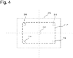
- Fig. 4 is a schematic view illustrating how positional alignment is established between the beam and the detector 202, and illustrates the detection range of the detector 202 and the scanning range of the beam.
- a rectangle indicated by an outer solid line represents a detection range 210 of the detector 202, in particular, the imaging region of camera 202a or the detection range of the sheet-shaped detector 202b.
- a broken line indicates a scanning range 212 of the beam, which is a range where the beam can scan by the scanning mechanism 174.
- a long dashed short dashed line in Fig. 4 indicates the center of the detection range of the detector 202.
- the detector 202 is disposed in such a manner that the entire scanning range 212 of the beam is contained in the detection range 210 of the detector 202.
- a reference mark 216 is placed at an arbitrary position inside the scanning range 212 of the beam.
- reference marks 216 are placed at the four corners of the scanning range 212 of the beam, one for each of the four corners.
- the reference mark may be one reference mark.
- the reference mark 216 may be placed at the center of the scanning range 212 of the beam.
- the reference mark 216 may be a feature preset on the focus surface of the AM apparatus 100, such as the surface of the base plate 114.
- the position of the reference mark 216 is irradiated with the beam, and the beam with which the reference mark 216 is irradiated is detected by the detector 202.
- This reveals the beam position detected by the detector 202 (the position of the reference mark 216 on the detector 202) and the position irradiated with the beam by the AM apparatus 100, such as the operation position of the scanning mechanism 174 (the operation position of the scanning mechanism 174 for irradiating the position of the reference mark 216 with the beam), thereby making it possible to confirm which position an arbitrary beam position detected by the detector 202 corresponds to on the focus surface of the AM apparatus.
- the beam is applied based on the execution data with use of the AM apparatus 100.
- the intensity of the laser 172 or the electron beam to be applied is set to a beam intensity lower than when the material powder 152 is sintered actually.
- the XY stage 112 is also put into operation based on the execution data for the fabrication, but the height of the lift table 108 is not changed.
- the position irradiated with the beam is detected by the detector 202.
- the beam position detected in the air AM process and the three-dimensional data of the fabrication target are compared and evaluated.
- the control device 200 can make the comparison and the evaluation between the beam position detected in the air AM process and the three-dimensional data D1 of the fabrication target.
- control device 200 functions as an evaluator for comparing and evaluating the beam position detected in the air AM process and the three-dimensional data D1 of the fabrication target. If the detected beam position does not match the three-dimensional data of the fabrication target, it is considered that there is an error in the execution data or the operation of the AM apparatus, in particular, the operation of the scanning mechanism 174. If the detected beam position does not match the three-dimensional data of the fabrication target and the AM apparatus 100 operates according to the recipe in the execution data, it is considered that there is an error in the execution data. Further, supplementarily, the execution data may be tested by virtually conducting a fabrication simulation without using the AM apparatus based on the execution data in a virtual space on a computer.
- Fig. 5 is a flowchart illustrating an AM process using the AM apparatus according to one embodiment.
- the three-dimensional data of the fabrication target is input to the control device 200.
- the control device 200 generates the execution data including the fabrication conditions and the recipe.
- the AM apparatus performs the above-described air AM process. If no fault is discovered in the air AM process, the fabricated object is manufactured by performing the actual AM process. If a fault is discovered in the air AM process, the air AM process is performed again after the fault is corrected.
- the AM apparatus allows the air AM process to be performed with use of the same AM apparatus before the fabrication target is actually fabricated by the AM apparatus, thereby allowing an erroneous operation of the AM apparatus and/or a defect in the data for the fabrication to be discovered before the manufacturing. Therefore, the operation of the AM apparatus, the fabrication data, and the recipe can be tested without consuming the material for the fabrication.
- the operations of the driving mechanism 110 which drives the lift table 108 of the AM apparatus 100, the XY stage 112 on the base plate 114, and the scanning mechanism 174 cannot be tested without the AM apparatus 100 actually put into operation, and therefore the virtual simulation on the computer is not sufficient to discover a malfunction in these driving mechanisms of the AM apparatus 100.
- the air AM process in the embodiment according to the present disclosure can test not only the execution data but also the operation mechanisms of the AM apparatus.
Landscapes
- Engineering & Computer Science (AREA)
- Physics & Mathematics (AREA)
- Chemical & Material Sciences (AREA)
- Materials Engineering (AREA)
- Optics & Photonics (AREA)
- Manufacturing & Machinery (AREA)
- Plasma & Fusion (AREA)
- Mechanical Engineering (AREA)
- Health & Medical Sciences (AREA)
- Toxicology (AREA)
- General Health & Medical Sciences (AREA)
- Automation & Control Theory (AREA)
- Powder Metallurgy (AREA)
- Laser Beam Processing (AREA)
Applications Claiming Priority (2)
| Application Number | Priority Date | Filing Date | Title |
|---|---|---|---|
| JP2019095153A JP7130596B2 (ja) | 2019-05-21 | 2019-05-21 | 造形物を製造するためのam装置およびam装置におけるビームの照射位置を試験する方法 |
| PCT/JP2020/012181 WO2020235204A1 (ja) | 2019-05-21 | 2020-03-19 | 造形物を製造するためのam装置およびam装置におけるビームの照射位置を試験する方法 |
Publications (2)
| Publication Number | Publication Date |
|---|---|
| EP3974084A1 true EP3974084A1 (de) | 2022-03-30 |
| EP3974084A4 EP3974084A4 (de) | 2023-07-05 |
Family
ID=73453421
Family Applications (1)
| Application Number | Title | Priority Date | Filing Date |
|---|---|---|---|
| EP20808750.2A Pending EP3974084A4 (de) | 2019-05-21 | 2020-03-19 | Am-vorrichtung zur herstellung eines formkörpers und verfahren zum prüfen der bestrahlungsposition in einem am-gerät |
Country Status (5)
| Country | Link |
|---|---|
| US (1) | US12459039B2 (de) |
| EP (1) | EP3974084A4 (de) |
| JP (1) | JP7130596B2 (de) |
| CN (1) | CN113874142B (de) |
| WO (1) | WO2020235204A1 (de) |
Family Cites Families (14)
| Publication number | Priority date | Publication date | Assignee | Title |
|---|---|---|---|---|
| DE4437284A1 (de) | 1994-10-18 | 1996-04-25 | Eos Electro Optical Syst | Verfahren zum Kalibrieren einer Steuerung zur Ablenkung eines Laserstrahls |
| JP4258567B1 (ja) * | 2007-10-26 | 2009-04-30 | パナソニック電工株式会社 | 三次元形状造形物の製造方法 |
| CN102574333B (zh) * | 2009-10-21 | 2015-07-29 | 松下电器产业株式会社 | 三维形状造型物的制造方法及其制造装置 |
| US9505057B2 (en) | 2013-09-06 | 2016-11-29 | Arcam Ab | Powder distribution in additive manufacturing of three-dimensional articles |
| KR20150115596A (ko) * | 2014-04-04 | 2015-10-14 | 가부시키가이샤 마쓰우라 기카이 세이사쿠쇼 | 3차원 조형 장치 및 3차원 형상 조형물의 제조 방법 |
| JP6087328B2 (ja) * | 2014-09-18 | 2017-03-01 | 株式会社ソディック | 積層造形装置 |
| CN106584855B (zh) | 2015-10-13 | 2018-09-11 | 三纬国际立体列印科技股份有限公司 | 立体物件成形装置的光源校正方法 |
| JP6655345B2 (ja) | 2015-10-20 | 2020-02-26 | 東レエンジニアリング株式会社 | 3次元物品の積層造形支援方法、コンピュータ・ソフトウェア、記録媒体および積層造形システム |
| DE102015223474A1 (de) * | 2015-11-26 | 2017-06-01 | Eos Gmbh Electro Optical Systems | Verfahren und Vorrichtung zum Herstellen eines dreidimensionalen Objekts |
| JP6177412B1 (ja) * | 2016-11-22 | 2017-08-09 | 株式会社ソディック | 積層造形装置 |
| DE102017202725B3 (de) * | 2017-02-21 | 2018-07-19 | SLM Solutions Group AG | Vorrichtung und Verfahren zum Kalibrieren eines Bestrahlungssystems, das zum Herstellen eines dreidimensionalen Werkstücks verwendet wird |
| KR102611837B1 (ko) | 2017-04-04 | 2023-12-07 | 엔라이트 인크. | 검류계 스캐너 보정을 위한 광학 기준 생성 |
| JP7030488B2 (ja) | 2017-11-27 | 2022-03-07 | 東芝ライフスタイル株式会社 | 冷蔵庫 |
| WO2019173000A1 (en) * | 2018-03-08 | 2019-09-12 | Velo3D, Inc. | Calibration in three-dimensional printing |
-
2019
- 2019-05-21 JP JP2019095153A patent/JP7130596B2/ja active Active
-
2020
- 2020-03-19 CN CN202080037410.7A patent/CN113874142B/zh active Active
- 2020-03-19 EP EP20808750.2A patent/EP3974084A4/de active Pending
- 2020-03-19 WO PCT/JP2020/012181 patent/WO2020235204A1/ja not_active Ceased
- 2020-03-19 US US17/610,877 patent/US12459039B2/en active Active
Also Published As
| Publication number | Publication date |
|---|---|
| EP3974084A4 (de) | 2023-07-05 |
| JP2020190009A (ja) | 2020-11-26 |
| US20220212261A1 (en) | 2022-07-07 |
| WO2020235204A1 (ja) | 2020-11-26 |
| CN113874142B (zh) | 2023-12-12 |
| JP7130596B2 (ja) | 2022-09-05 |
| US12459039B2 (en) | 2025-11-04 |
| CN113874142A (zh) | 2021-12-31 |
Similar Documents
| Publication | Publication Date | Title |
|---|---|---|
| US10336008B2 (en) | Method for automatic calibration of a device for generative production of a three-dimensional object | |
| US10914677B2 (en) | System and method for calibrating a melt pool monitoring system of an additive manufacturing machine | |
| US11993007B2 (en) | Measuring system for a device for the generative manufacturing of a three-dimensional object | |
| CN111867754A (zh) | 用于使多束照射系统对准的方法 | |
| US20230122426A1 (en) | Method for manufacturing three-dimensional shaped object, additive manufacturing apparatus, and article | |
| EP4005699A1 (de) | Vorrichtung zur generativen fertigung | |
| US12459039B2 (en) | AM apparatus for manufacturing a fabricated object and method for testing an irradiation position of a beam in the AM apparatus | |
| KR102170152B1 (ko) | 표면 처리 장치 | |
| US20200050169A1 (en) | Method for calibrating an apparatus for additively manufacturing three-dimensional objects | |
| US20220234285A1 (en) | Am apparatus | |
| US12377602B2 (en) | Post-exposure unit | |
| KR102419823B1 (ko) | 멀티 하전 입자 빔 묘화 장치 | |
| EP3521026B1 (de) | Verfahren zur bestimmung von positionsdaten für eine vorrichtung zur generativen fertigung dreidimensionaler objekte | |
| JP7004070B2 (ja) | 三次元造形装置及び三次元造形方法 | |
| KR20190102289A (ko) | 노광 장치, 기판 처리 장치, 기판의 노광 방법 및 기판 처리 방법 | |
| EP4253008A1 (de) | Vorrichtung zur dreidimensionalen modellierung und verfahren zur dreidimensionalen modellierung | |
| KR102834127B1 (ko) | 정보 처리 장치, 정보 처리 방법, 및 컴퓨터 프로그램 | |
| RU2819941C1 (ru) | Блок дополнительной экспозиции | |
| JP2007212861A (ja) | 露光装置 | |
| KR20110035975A (ko) | 검사 장치 및 검사 방법 |
Legal Events
| Date | Code | Title | Description |
|---|---|---|---|
| STAA | Information on the status of an ep patent application or granted ep patent |
Free format text: STATUS: THE INTERNATIONAL PUBLICATION HAS BEEN MADE |
|
| PUAI | Public reference made under article 153(3) epc to a published international application that has entered the european phase |
Free format text: ORIGINAL CODE: 0009012 |
|
| STAA | Information on the status of an ep patent application or granted ep patent |
Free format text: STATUS: REQUEST FOR EXAMINATION WAS MADE |
|
| 17P | Request for examination filed |
Effective date: 20211116 |
|
| AK | Designated contracting states |
Kind code of ref document: A1 Designated state(s): AL AT BE BG CH CY CZ DE DK EE ES FI FR GB GR HR HU IE IS IT LI LT LU LV MC MK MT NL NO PL PT RO RS SE SI SK SM TR |
|
| DAV | Request for validation of the european patent (deleted) | ||
| DAX | Request for extension of the european patent (deleted) | ||
| RAP3 | Party data changed (applicant data changed or rights of an application transferred) |
Owner name: EBARA CORPORATION |
|
| RIN1 | Information on inventor provided before grant (corrected) |
Inventor name: SHINOZAKI, HIROYUKI |
|
| A4 | Supplementary search report drawn up and despatched |
Effective date: 20230602 |
|
| RIC1 | Information provided on ipc code assigned before grant |
Ipc: B22F 12/49 20210101ALI20230529BHEP Ipc: B33Y 50/02 20150101ALI20230529BHEP Ipc: B22F 10/31 20210101ALI20230529BHEP Ipc: B22F 10/28 20210101ALI20230529BHEP Ipc: B29C 64/393 20170101ALI20230529BHEP Ipc: B29C 64/268 20170101ALI20230529BHEP Ipc: B29C 64/153 20170101ALI20230529BHEP Ipc: B33Y 30/00 20150101ALI20230529BHEP Ipc: B33Y 10/00 20150101ALI20230529BHEP Ipc: B23K 26/34 20140101ALI20230529BHEP Ipc: B23K 26/21 20140101ALI20230529BHEP Ipc: B22F 3/16 20060101ALI20230529BHEP Ipc: B22F 3/105 20060101AFI20230529BHEP |
|
| RAP3 | Party data changed (applicant data changed or rights of an application transferred) |
Owner name: EBARA CORPORATION |
|
| STAA | Information on the status of an ep patent application or granted ep patent |
Free format text: STATUS: EXAMINATION IS IN PROGRESS |
|
| 17Q | First examination report despatched |
Effective date: 20250409 |
|
| GRAP | Despatch of communication of intention to grant a patent |
Free format text: ORIGINAL CODE: EPIDOSNIGR1 |
|
| STAA | Information on the status of an ep patent application or granted ep patent |
Free format text: STATUS: GRANT OF PATENT IS INTENDED |
|
| INTG | Intention to grant announced |
Effective date: 20250916 |