EP3974071B1 - Mécanisme de séchage portable - Google Patents
Mécanisme de séchage portable Download PDFInfo
- Publication number
- EP3974071B1 EP3974071B1 EP21197654.3A EP21197654A EP3974071B1 EP 3974071 B1 EP3974071 B1 EP 3974071B1 EP 21197654 A EP21197654 A EP 21197654A EP 3974071 B1 EP3974071 B1 EP 3974071B1
- Authority
- EP
- European Patent Office
- Prior art keywords
- drying
- shaft
- drying mechanism
- neck
- panels
- Prior art date
- Legal status (The legal status is an assumption and is not a legal conclusion. Google has not performed a legal analysis and makes no representation as to the accuracy of the status listed.)
- Active
Links
Images


Classifications
-
- F—MECHANICAL ENGINEERING; LIGHTING; HEATING; WEAPONS; BLASTING
- F26—DRYING
- F26B—DRYING SOLID MATERIALS OR OBJECTS BY REMOVING LIQUID THEREFROM
- F26B5/00—Drying solid materials or objects by processes not involving the application of heat
- F26B5/16—Drying solid materials or objects by processes not involving the application of heat by contact with sorbent bodies, e.g. absorbent mould; by admixture with sorbent materials
-
- F—MECHANICAL ENGINEERING; LIGHTING; HEATING; WEAPONS; BLASTING
- F26—DRYING
- F26B—DRYING SOLID MATERIALS OR OBJECTS BY REMOVING LIQUID THEREFROM
- F26B7/00—Drying solid materials or objects by processes using a combination of processes not covered by a single one of groups F26B3/00 and F26B5/00
-
- A—HUMAN NECESSITIES
- A47—FURNITURE; DOMESTIC ARTICLES OR APPLIANCES; COFFEE MILLS; SPICE MILLS; SUCTION CLEANERS IN GENERAL
- A47L—DOMESTIC WASHING OR CLEANING; SUCTION CLEANERS IN GENERAL
- A47L19/00—Drying devices for crockery or table-ware, e.g. tea-cloths
-
- B—PERFORMING OPERATIONS; TRANSPORTING
- B08—CLEANING
- B08B—CLEANING IN GENERAL; PREVENTION OF FOULING IN GENERAL
- B08B9/00—Cleaning hollow articles by methods or apparatus specially adapted thereto
- B08B9/08—Cleaning containers, e.g. tanks
- B08B9/087—Cleaning containers, e.g. tanks by methods involving the use of tools, e.g. brushes, scrapers
-
- F—MECHANICAL ENGINEERING; LIGHTING; HEATING; WEAPONS; BLASTING
- F26—DRYING
- F26B—DRYING SOLID MATERIALS OR OBJECTS BY REMOVING LIQUID THEREFROM
- F26B21/00—Arrangements for supplying or controlling air or other gases for drying solid materials or objects
- F26B21/50—Ducting arrangements from the source of air or other gases to the materials or objects being dried
-
- F—MECHANICAL ENGINEERING; LIGHTING; HEATING; WEAPONS; BLASTING
- F26—DRYING
- F26B—DRYING SOLID MATERIALS OR OBJECTS BY REMOVING LIQUID THEREFROM
- F26B25/00—Details of general application not covered by group F26B21/00 or F26B23/00
-
- F—MECHANICAL ENGINEERING; LIGHTING; HEATING; WEAPONS; BLASTING
- F26—DRYING
- F26B—DRYING SOLID MATERIALS OR OBJECTS BY REMOVING LIQUID THEREFROM
- F26B25/00—Details of general application not covered by group F26B21/00 or F26B23/00
- F26B25/22—Controlling the drying process in dependence on liquid content of solid materials or objects
-
- F—MECHANICAL ENGINEERING; LIGHTING; HEATING; WEAPONS; BLASTING
- F26—DRYING
- F26B—DRYING SOLID MATERIALS OR OBJECTS BY REMOVING LIQUID THEREFROM
- F26B5/00—Drying solid materials or objects by processes not involving the application of heat
- F26B5/12—Drying solid materials or objects by processes not involving the application of heat by suction
Definitions
- bacteria, fungi, and viruses have the capacity to flourish in areas throughout the house, including portable containers or other confined areas.
- Some disease-causing bacteria, such as Salmonella , E. coli , and Listeria can cause illness if not properly cleaned and disinfected.
- the Centers for Disease Control and Prevention estimates that in the United States of America approximately 48 million people get sick from foodborne illness per year. Most of these illnesses are from infections caused by a variety of bacteria and viruses which can proliferate in an optimal environment.
- the kitchen in particular can be a breeding ground for these issues.
- Many kitchen surfaces and accessories offer prime locations for bacterial growth.
- Dish towels for example, are known conduits for bacterial growth, because these can provide nutrients and moisture for bacteria to grow. Bacteria can survive at least two days on surfaces, which is more than enough time to spread somewhere else if not disinfected. Kitchen countertops may have bacteria on them as well, which is why cleaning them before preparing food is highly recommended.
- fungus can also appear and grow in containers in the form of mold. If presented with some of the conditions noted above, such as water, warmth, and a dark space, fungus can start to appear as soon as 48 hours if the container was not properly cleaned and dried.
- Many containers have restricted access to the full interior due to narrow necks, depth, width, or odd shape of the container, among other attributes. This makes it very difficult to get a container completely dry using traditional methods.
- Some examples of current methods to dry these kinds of containers may include air drying by using a peg or drying rack system, or by inserting paper towels or cloth towels into the container, which risks exposure to bacteria if those items aren't clean and dry before use.
- Some people try to navigate the container by guiding a paper towel or cloth towel with another long narrow utensil, to hopefully reach the small amounts of liquid still left on the sides and bottom of the container.
- pegboards and drying racks take up precious wall and countertop space. Properly air drying can take up to 48 hours. Meanwhile, using dirty dish towels to dry containers potentially introduces bacteria into food and beverage containers.
- US 8 336 156 B1 discloses a device to aid in drying baby bottles after washing comprising a plastic handle, a flexible "wand", and a drying head having a plurality of absorbent cloth strips.
- the cloth end of the device is reciprocated therewithin a baby bottle after it has been washed and rinsed.
- the cloth strips and drying head are removably attached thereto the handle assembly and may be released for washing, drying, or and/or replacement purposes.
- US 7 370 383 B1 discloses a brush device for cleaning an interior of a bottle that includes a shaft that is insertable into an interior of a bottle. Each of a plurality of bristle sets is coupled to the shaft and is positioned adjacent an end of the shaft. Each of the bristle sets is insertable into the interior of the bottle to scrub the bottle. A handle is coupled to an end of the shaft distal to the bristle sets. The handle is graspable to facilitate manipulation of the shaft and the bristle sets to scrub the interior of the bottle.
- WO 2019/197039 A1 discloses a flexible connecting piece for a rod handle and a cleaning attachment.
- the flexible connecting piece comprises a first connecting region for attaching the cleaning attachment, a second connecting region for attaching the rod handle, and a flexible portion, which connects the first connecting region and the second connecting region.
- the flexible portion comprises a flexible bar having a longitudinal axis, on which bar at least two at least partially peripherally extending rib portions are arranged.
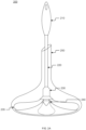
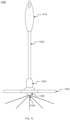
- the mechanism comprises a grip, shaft, neck, drying panels, and tip.
- the shaft may comprise one or multiple pieces, wherein the length may be extended or compressed to accommodate containers of different heights or lengths.
- the grip may comprise a button or other activation mechanism, such as a switch or rip cord, to modify the configuration of the portable drying mechanism.
- a portable drying mechanism may be reused for a limited number of uses and discarded, or may be used long-term when properly maintained after each use, depending on the material.
- a button may release interchangeable components of the portable drying mechanism.
- the button may allow the shaft to extend.
- the button may activate an electrical drying response such as, but not limited to, a water vacuum, or rotating drying material.
- the shaft may comprise a hollow cavity for material retention.
- the shaft may comprise a telescoping aspect that allows for extension and retraction. In some embodiments, extenders may be attached to achieve a desired length. In some implementations, the shaft may comprise a flexible portion to dry containers with complex shapes. In some aspects, the neck may comprise a drying material that protrudes at a predetermined distance from the portable drying mechanism. In some embodiments, the tip may comprise a sensor to verify dryness within a dried container.
- the portable drying mechanism may comprise components that may allow the portable drying mechanism to access limited geometry within containers.
- the portable drying mechanism may provide sensory feedback to indicate the internal state of the container where stringent drying is imperative such as in a scientific setting.
- the portable drying mechanism may comprise components that may be sterilized for use in laboratories or medical settings, such as in the hospital.
- the present disclosure relates to a portable drying mechanism that comprising: a grip configured to allow for gripping by a hand, where the grip comprises a first grip end and a second grip end; a shaft comprising a first shaft end and a second shaft end, where the first shaft end is couplable to the second grip end; a neck comprising: a first neck end, where the first neck end is couplable to the second shaft end, a second neck end, and a plurality of drying panels configured to extend from the second neck end; a tip comprising a first tip end and a second tip end, where the first tip end is couplable to the second neck end; and an attachment mechanism configured to couple the neck to one or both the second shaft end and the first tip end.
- the plurality of drying panels may comprise a synthetic material. In some implementations, the plurality of drying panels may comprise a natural material.
- the attachment mechanism may comprise one or more of a threaded connection, a bayonet coupling, a snap-in-place mechanism, a sliding mechanism, ball and joint mechanism, and a button mechanism.
- the shaft may be flexible. In some embodiments, a length of the shaft may be adjustable. In some implementations, the shaft may comprise a telescoping mechanism.
- the shaft may comprise multiple pieces that integrate to extend or compress a length of the shaft incrementally.
- the second tip end may comprise a sensor.
- one or more of the grip, shaft, neck, and tip are hollow.
- the plurality of drying panels may be replaceable.
- the plurality of drying panels may be retractable.
- the plurality of drying panels may be reusable.
- the neck may comprise a flexible portion configured to allow the shaft to bend.
- the plurality of drying panels may be flexible.
- the shaft may be interchangeable.
- the rotation of the plurality of drying panels may be configured to be automated or manually manipulated.
- the portable drying mechanism may comprise a release mechanism configured to release the attachment mechanism.
- the portable drying mechanism may be wholly or partly reusable.
- the plurality of drying panels may be detachable and replaceable.
- Drying mechanism refers to a drying tool comprising a grip, elongated shaft and neck with detachable drying panels and tip, wherein the drying mechanism may be used to dry the interior of a container or other hard-to-reach areas.
- the mechanism may comprise a plurality of components that may be either detachable, replaceable and or reusable.
- the drying mechanism may comprise disposable drying heads, wherein each may be used for one or more drying solutions in a plurality of containers.
- Container refers to a vessel that may comprise an enclosed or partially enclosed surface area that may collect or retain liquid or moisture.
- liquid and other non-limiting fluids may be absorbed by a drying mechanism.
- the container may hold one or more liquids within its dimensions.
- a container may comprise a decanter, champagne flute, water bottle, vase, test tube, beaker, or carafe.
- the drying mechanism 100 comprises a grip 110. Furthermore, the drying mechanism comprises a shaft 120. Moreover, the shaft 120 comprises an attachment mechanism that allows the shaft 120 to connect to a neck 130. The neck 130 comprises a tip 140. Furthermore, according to the present invention the neck 130 comprises a plurality of drying panels 135. In some embodiments, the drying panels 135 may be flexible to dry unique internal contours of containers or confined spaces.
- the drying mechanism 100 may comprise a singular piece, wherein all components are attached. In some aspects, the drying mechanism 100 may comprise individual pieces, wherein each component may be separated from the drying mechanism 100. For example, the grip 110 may disconnect from the shaft 120 and be reattached after being cleaned or serviced. Additionally, the shaft 120 may comprise one or several individual pieces that integrate to allow for extension and compression of the length of the shaft 120. This may allow the drying mechanism 100 to be used on containers of all different sizes and shapes. In some embodiments, at least a portion of the shaft may be flexible, which may allow for more comprehensive reach and access to spaces within a container.
- the plurality of drying panels 135 may be removable from the drying mechanism 100.
- the plurality of drying panels 135 may comprise one material or several materials, arranged randomly or in a pattern.
- the plurality of drying panels 135 may comprise a wholly flexible or partly flexible material.
- the plurality of drying panels 135 may comprise a base material and a topical, textured material further comprising flexible or rigid bumps, grooves, points, or other non-limiting textures. This may aid in the effective drying of the target container, especially one having a particularly intricate configuration.
- the plurality of drying panels 135 may be reused for a limited number of uses and discarded or may be used long-term when properly maintained after each use, depending on the material.
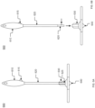
- the neck 230 of the drying mechanism 200 may extend to the distal end of the interior of the container 250, 251, 252.
- the shaft 220 may extend into an opening of a container 250, 251, 252 to allow the tip 240 and the drying panels 235 to reach the edges within the container 250, 251, 252.
- the neck 230 may comprise a plurality of drying panels 235.
- the drying panels 235 may be flexible to dry unique internal contours of containers.
- the drying panels 235 may comprise one or more materials, whereby liquid may be absorbed, wholly or in part, into the drying panels 235.
- the tip 240 may assist the drying mechanism 200 in removing liquid from the corners of a plurality of shapes.
- the tip 240 may remove small amounts of water in the distal corners of a decanter after the decanter has been washed.
- the tip 240 may guide the drying panels 235 within a container, allowing for more precise drying.
- the neck 230 may comprise flexible material, wherein the drying mechanism 200 may be inserted into more than one shape container.
- a container 250, 251, 252 may comprise a smaller opening and a wider enclosure like a water bottle or a baby bottle, wherein a drying mechanism 200 may be inserted and freely move around to absorb liquid within the container.
- the drying mechanism 200 may remove liquid from generic container types such as plastic containers, narrow-necked water bottles, baby bottles, wine glasses, and laboratory test beakers, as a non-limiting list.
- a decanter neck may be easily dried by a drying mechanism 200 with a thinner shaft 220, wherein the drying mechanism 200 may also reach the base of the interior of the container.
- the shaft 220 may comprise a plurality of interchangeable lengths, wherein the drying mechanism 200 may reach into one or more container 250, 251, 252 bases.
- the plurality of interchangeable lengths may be incremental, such as through a telescoping mechanism, or freely adjustable.
- the drying mechanism 200 may interface with shafts 220 of a plurality of predetermined lengths to fit a plurality of containers 250, 251, 252.
- the shaft 220 may comprise a variable thickness to comprise a plurality of lengths on the same shaft 220.
- a variable thickness may allow the shaft 220 to access narrow openings that are shallow enough to require only the first portion of the shaft 220 to enter the container 251 while simultaneously providing a thicker shaft closer to the neck to provide increased stability during use.
- the thickness of the shaft 220 may be uniformly predetermined, tapered, adjustable, or any combination thereof.
- the shaft 220 and neck 230 may be removed from the tip 240.
- the shaft 220 may comprise locking mechanisms on its ends, wherein the grip 210, neck 230, and tip 240 may connect.
- the drying mechanism 200 may comprise a smaller width shaft 220 wherein, the drying mechanism 200 may be placed into the opening of a champagne flute.
- a wider version of the shaft 220 may be used for a deeper container, such as a flower vase, where a sturdier shaft 220 may be needed, and the depth of the container is longer.
- a user may disconnect and reconnect one or more shafts 220 to coincide with the container being dried by the drying mechanism 200.
- the grip 310 may interface with a plurality of shafts 320, 321, 322.
- the shaft may attach to the neck 330 via a threaded hole.
- the tip 340 may be detachable from the neck 330.
- the tip 340 may incorporate a non-scratching connection piece, such as rubber or silicone, as non-limiting examples.
- the neck 330 may comprise a locking mechanism, wherein the neck 330 may be fastened to the shafts 320, 321, 322 with or without a tip.
- the neck 330 may comprise two connectors that may couple to one another and fixate the neck 330 to the drying mechanism 300.
- the shaft 321 may comprise an extension system, wherein the length of the drying mechanism 300 may be adjusted.
- the orientation of the shaft 321 may be adjustable.
- a container 350 may comprise significant curvature.
- the shaft 321 may comprise a flexible portion that allows the neck 330 to match the curvature of the container 350 body so that the drying panels 335 can reach and dry the curve of the container 350.
- the neck 330 may comprise a plurality of drying panels 335.
- the drying panels 335 may be flexible to dry unique internal contours of containers.
- the drying panels 335 may come in one or more shapes and sizes.
- the drying mechanism 300 may comprise a plurality of interchangeable shafts 320, 321, 322.
- the shaft 320, 322 may comprise a plurality of lengths and widths. In some aspects, a longer shaft 322 may be used to reach a plurality of depths of containers. In some embodiments, a thicker shaft 322 may be used for heavy-duty containers, whereby the drying mechanism 300 may remain intact.
- a thinner shaft 320 may comprise a lower structural integrity that may inhibit the application of a large amount of force that may be necessary to maneuver the drying mechanism 300 within the container 350.
- a thicker shaft 322 may provide the drying mechanism 300 with sufficient structural integrity for more strenuous use.
- the neck 330 may comprise one or more sizes, wherein one or more sized shafts 320, 321, 322 may adapt into the neck 330.
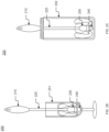
- the drying mechanism 400 comprises a grip 410.
- the grip 410 may comprise a storage method that may interface with an external surface such as a suction cup, as a non-limiting example.
- the storage method may allow the user to place the drying mechanism 400 in a proximal location to an area of frequent use.
- the drying mechanism 400 comprises a shaft 420.
- the grip 410 and the shaft 420 may be regions of a single component. 2.
- the shaft 420 connects to the detachable neck 430 via an attachment mechanism 425.
- the neck 430 may comprise a tip 440.
- the plurality of drying panels 435 may detach from the neck 430.
- the tip 440 may comprise an absorbent material, wherein the drying mechanism 400 may absorb liquid in the corners of containers.
- the flexible drying panels 435 may comprise a material that may retain fluid as the flexible drying panels are compressed when removed from a container.
- the attachment mechanism 425 may be used on a smaller drying mechanism 400, then removed and attached to larger drying mechanism 400 for a plurality of interchangeable uses.
- the attachment mechanism 425 may comprise a slot, wherein a spring-loaded button may be inserted.
- the button may be pressed to remove the attachment mechanism 425 from the drying mechanism 400.
- the button may improve the accessibility of interchanging parts, including fresh drying heads, between drying mechanisms 400.
- the drying mechanism 400 may comprise slots on any part of its outer surface. In some aspects, the drying mechanism 400 may comprise a plurality of slots, wherein the neck 430 may attach at one or more lengths. In some embodiments, two or more slots may be located on the side of the drying mechanism 400. In some implementations, the drying mechanism 400 may comprise a plurality of grooves, wherein the neck 430 may attach at one or more lengths by sliding and locking into one or more grooves, such as for a bayonet coupling, as a non-limiting example.
- the drying mechanism 500 comprises a grip 510.
- the grip 510 may comprise an opening for attachment to an external component.
- the shaft 520 connects to the neck 530 via an attachment mechanism 525.
- the neck 530 comprises a tip 540.
- the neck 530 comprises a plurality of drying panels 535.
- the plurality of drying panels 535 may be uniform or varied, comprising different sizes, shapes, and textures.
- the plurality of drying panels 535 may comprise two or more flexible materials, so as to wipe dry glass containers.
- the drying panels 535 may be flexible to dry unique internal contours of containers.
- the flexibility of the drying panels 535 may increase as the drying panels 535 absorb liquid.
- the drying panels 535 may retain fluid when compressed, allowing for more effective drying with limited risk of inadvertently adding liquid back into a container when removing the drying mechanism 500.
- compression may occur if the neck of the container is small and the drying panels 535 may fold to fit through the opening.
- the drying mechanism 500 Z comprises a shaft 520.
- the shaft 520 may comprise a telescoping mechanism 515, wherein the drying mechanism 500 may be adjusted to a plurality of lengths.
- the shaft 520 may comprise one or more telescoping mechanisms 515.
- the telescoping mechanisms 515 may comprise a plurality of lengths, that allow the drying mechanism 500 to reach different regions of a container or different sized container.
- the shaft 520, 521, 522 may comprise one or more predetermined lengths that may be interchangeable to accommodate for containers of a plurality of depths, each comprising their own attachment mechanism 525, 526, 527, 528.
- the shaft 520, 521, 522 may comprise three shafts 520, 521, 522 to reach the bottom of a carafe and then the user may remove one or more shafts 521, 522 to use the drying mechanism 500 for a shallow test beaker.
- the plurality of lengths may be predetermined or freely customizable by the user.
- the shaft 520 may comprise locking mechanisms 525, 526, 527, 528 that allow for locking of the different lengths.
- the locking mechanism may be activated by twisting the shaft 520. For example, the shaft 520 may be twisted clockwise to tighten the locking mechanism, whereas twisting the shaft 520 counterclockwise may loosen the locking mechanism.
- the drying mechanism 600 comprises a grip 610.
- the drying mechanism 600 Z comprises a shaft 620 coupled to the grip 610.
- the shaft 620 connects to the neck 630 via an attachment mechanism 625.
- the attachment mechanism 625 may be actuated by a release mechanism 615.
- the neck 630 may comprise a tip 640.
- the grip 610 may comprise a release mechanism 615, wherein the neck 630 may be removed from the drying mechanism 600.
- the release mechanism 615 may comprise a button or sliding channel, as non-limiting examples. In some implementations, pressing on the button may allow for the attachment and disconnection of the neck 630 from the drying mechanism 600.
- the shaft 620 may be interchanged on the drying mechanism 600. In some implementations, a larger shaft 620 may be attached to the drying mechanism 600, wherein a more durable version of the drying mechanism 600 may be used.
- the attachment mechanism 625 may allow portions of the drying mechanism 600 to be interchangeable with other drying mechanisms 600.
- the attachment mechanism 625 may attach a neck 630 to a smaller drying mechanism 600, then removed and attached to larger drying mechanism 600 for a plurality of uses.
- the drying mechanism 700 comprises grip 710.
- the drying mechanism 700 comprises a shaft 720 coupled to the grip 710.
- the shaft 720 connects to the neck 730 via an attachment mechanism 725.
- the neck 730 comprises a tip 740.
- the neck 730 may comprise threaded material, whereby the drying panels 735 of the drying mechanism 700 may be retractable.
- the retraction may be activated via a retraction mechanism 715.
- the retraction may be actuated through manual rotation of the neck 730.
- the drying mechanism 700 may enter a greater plurality of containers by accessing containers with narrow entry openings.
- the retraction mechanism 715 may uniformly or selectively retract the drying panels 735.
- the drying material of the drying panels 735 may comprise a plurality of lengths.
- the predetermined lengths may be adjusted via retraction that allows for drying containers with a plurality of internal surfaces.
- the neck 730 of the drying mechanism 700 may retract the drying material for the narrow neck of a flower vase and then the same neck 730 may extend the drying panels 735 to dry the base of a wide mouth thermos, as a non-limiting example.
- the attachment mechanism 725 may comprise a locking mechanism, wherein the tip 740 remains stable with the drying mechanism 700.
- the locking mechanism may comprise a button, snap-closure, or channel system, as non-limiting examples.
- the drying mechanism 700 may comprise a plurality of threaded shafts 720, wherein one or more tips 740 may be attached.
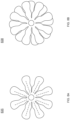
- drying panels 835, 836, 837, 838, 839 are illustrated.
- the drying panels 835, 836, 837, 838, 839 may comprise one or multiple shapes, sizes, materials, or any combination thereof. The diversity of shapes may be interchanged to improve the drying qualities of the drying mechanism for specific applications.
- the drying panels 835, 836, 837, 838, 839 may comprise two or more layers of drying panels 838. These layers may allow the drying material to dry a range of containers, which may comprise a plurality of textures, materials, and shapes, as non-limiting characteristics.
- the drying panels 835 may comprise stitching or other non-limiting composites that may provide structural support and rigidity to the drying panels 835, as non-limiting attributes.
- the drying panels 835 may comprise a thicker thread that binds layers within the drying panels 835.
- the thread may be intentionally placed along the center of the drying panels 835 to provide rigidity. This rigidity may allow the drying panels 835 to retain sufficient composition to maneuver into distal regions of a container that may contain moisture.
- the thread may be placed along the outer edges of the drying panels 835.
- the drying panels 835, 836, 837, 838, 839 may comprise a plurality of materials, depending on what kind of liquids need to be absorbed. In some embodiments, the drying panels 838 may be offset and comprise one or more layers. In some aspects, the drying panels 835, 836, 837, 838, 839 may comprise one or more absorbent material, such as synthetic, organic, or natural materials. As a non-limiting example, the drying panels 835, 836, 837, 838, 839 may be texturized to both absorb liquid from and wipe dry a glass container.
- a thicker material may be used to absorb larger collections of liquid, whereas a thinner material may be used for less liquid.
- a plurality of materials may be used to absorb various liquids, such as water, milk, oil, chemicals, and other non-limiting examples.
- the drying mechanism 900 comprises a grip 910.
- the drying mechanism 900 comprises a shaft 920 coupled to the grip 910.
- the neck 930 comprises a plurality of drying panels 935.
- the neck 930 comprises a tip 940.
- the drying mechanism 900 may comprise an activation mechanism 915, wherein an airway system is engaged.
- the drying mechanism 900 may comprise a hollow interior, wherein the airway system may be located.
- the airway system may extract fluid through the drying mechanism 900.
- the drying mechanism 900 may be able to suction fluid from the bottom of a container in addition to absorbing moisture with the plurality of drying panels 935. This may allow for an even drier result than otherwise possible.
- the tip 940 may comprise an opening, wherein air may enter the mechanism.
- the tip 940 may comprise a suction mechanism, wherein moisture may be extracted from a container.
- the suction mechanism may be activated using an activation mechanism 915 located on the grip 910.
- the suction mechanism may be directly connected to the tip 940 of the drying mechanism 900.
- the suction mechanism may extract remaining liquid within the container that may otherwise overwhelm the drying panels 935 of the drying mechanism 900 and prevent thorough drying of the interior of the container.
- the suction mechanism may pull fluid toward the drying panels 935, allowing for more effective drying.
- the tip 940 may activate the airway opening when the drying panels 935 begin their retraction into the neck 930 of the drying mechanism 900.
- the shaft 920 may comprise a ball valve, wherein the valve prevents airflow until the tip 940 retracts the drying panels 935 that may otherwise impede airflow from the drying mechanism 900.
- the airway of the drying mechanism 900 may remain closed while the airway system is inactive, but when the drying material of the drying panels 935 retract to a specific length the airway may then expel air or fluid, as non-limiting examples.
- the drying mechanism 1000 may comprise a grip 1010.
- the drying mechanism 1000 may comprise a shaft 1020 coupled to the grip 1010.
- the neck 1030 may comprise a plurality of drying panels 1035.
- the neck 1030 may comprise a tip 1040.
- the tip 1040 may comprise a sensor 1045.
- a light may be used at the end of the drying mechanism 1000, wherein the user may need visual clearance at the bottom of a container or other hard-to-reach areas. In some implementations, a light may be used to aid the sensor in revealing moist areas at the bottom of a container. In some aspects, the sensor 1045 may notify the drying mechanism 1000 of potential moist areas within a container.
- the corner of a container may have been missed by manual use of the drying mechanism 1000 and the sensor 1045 may notify the user when the drying mechanism 1000 encounters a moist area.
- the drying mechanism 1000 may comprise an audio source, wherein a noise may signal the user to a moist area.
- the sensor 1045 may be useful if the interior of the container is not visible to the user.
- the drying mechanism 1000 may comprise a vibration mechanism, wherein a moist area may indicate the sensor 1045 to trigger the vibration mechanism in the drying mechanism 1000.
- the vibrations may indicate when the drying mechanism has come into contact with a moist nonvisible surface of the interior of the container, such as an opaque glass or dark surface.
- the drying mechanism 1100 comprises a grip 1110.
- the drying mechanism 1100 comprises a shaft 1120.
- the shaft 1120 connects to the neck 1130 via an attachment mechanism.
- the neck 1130 comprises a tip.
- the neck 1130 comprises a plurality of drying panels 1135.
- the drying mechanism 1100 may comprise a rotation mechanism 1115 that allows the neck 1130 to rotate.
- the neck 1130 may rotate to accentuate the drying panels 1135.
- the grip 1110 may comprise the rotation mechanism 1115, wherein the rotation of the neck 1130 is activated by pressing or pulling it.
- the rotation mechanism 1115 may allow for manual control of the drying mechanism 1100 to ensure thorough drying of the container.
- the rotation mechanism 1115 may comprise a speed adjustment mechanism, wherein the speed of the drying mechanism 1100 varies. In some aspects, the speed of the drying mechanism 1100 may be adjusted incrementally or freely according to user customization. In some embodiments, rotation may be mechanically activated. As an example, a ripcord may protrude from the grip of the drying mechanism, thereby allowing for manual rotation of the drying panels 1135. In some aspects, rotation may be automatic and the drying mechanism 1100 may require a power source, such as a disposable or rechargeable battery, as non-limiting examples.
- the external device 1260 may act as a charging stand for the drying mechanism 1200.
- the drying mechanism 1200 may interface with an external device 1260 that may provide power to the drying mechanism 1200.
- the external device 1260 may comprise a port, wherein the drying mechanism 1200 may be charged.
- the external device 1260 may comprise a light, whereby it notifies of the drying mechanism 1200 being fully charged.
- the drying mechanism 1200 may comprise a locking mechanism 1215 to attach the drying mechanism 1200 to the external device 1260.
Landscapes
- Engineering & Computer Science (AREA)
- Mechanical Engineering (AREA)
- General Engineering & Computer Science (AREA)
- Health & Medical Sciences (AREA)
- Life Sciences & Earth Sciences (AREA)
- Molecular Biology (AREA)
- Drying Of Solid Materials (AREA)
- Details Of Rigid Or Semi-Rigid Containers (AREA)
Claims (15)
- Mécanisme de séchage portable (400, 500, 600, 700) comprenant :une poignée (410, 510, 610, 710) configurée pour permettre la préhension d'une main, dans lequel la poignée (410, 510, 610, 710) comprend une première extrémité de poignée et une deuxième extrémité de poignée ;un arbre (420, 520, 620, 720) comprenant une première extrémité d'arbre et une deuxième extrémité d'arbre, dans lequel la première extrémité d'arbre peut être accouplée à la deuxième extrémité de poignée ;un col (430, 530, 630, 730) comprenant :une première extrémité de col, dans lequel la première extrémité de col peut être accouplée à la deuxième extrémité d'arbre,une deuxième extrémité de col, etune pluralité de panneaux de séchage (435, 535, 635, 735) configurée pour s'étendre à partir de la deuxième extrémité de col ;une pointe (440, 540, 640, 740) comprenant une première extrémité de pointe et une deuxième extrémité de pointe, dans lequel la première extrémité de pointe peut être accouplée à la deuxième extrémité de col ; etun mécanisme de fixation (425, 525, 625, 725) configuré pour accoupler le col (430, 530, 630, 730) à la deuxième extrémité d'arbre et/ou à la première extrémité de pointe.
- Mécanisme de séchage portable (400, 500, 600, 700) selon la revendication 1, dans lequel la pluralité de panneaux de séchage (435, 535, 635, 735) comprend un matériau synthétique ou un matériau naturel.
- Mécanisme de séchage portable (400, 500, 600, 700) selon la revendication 1, dans lequel le mécanisme de fixation (425, 525, 625, 725) comprend un raccord fileté et/ou un accouplement par baïonnette et/ou un mécanisme d'encliquetage et/ou un mécanisme de coulissement et/ou un mécanisme de joint à rotule et/ou et un mécanisme de bouton.
- Mécanisme de séchage portable selon la revendication 1, dans lequel l'arbre est flexible.
- Mécanisme de séchage portable (500) selon la revendication 1, dans lequel une longueur de l'arbre (520) est réglable, ou dans lequel l'arbre (520) comprend un mécanisme télescopique, ou dans lequel l'arbre (520) comprend de multiples pièces qui s'intègrent pour étendre ou comprimer une longueur de l'arbre (520) de manière incrémentielle.
- Mécanisme de séchage portable selon la revendication 1, dans lequel la deuxième extrémité de pointe comprend un capteur.
- Mécanisme de séchage portable (500) selon la revendication 1, dans lequel un ou plusieurs parmi la poignée (510), l'arbre (520), le col (530), et la pointe sont creux/ses.
- Mécanisme de séchage portable (500) selon la revendication 1, dans lequel la pluralité de panneaux de séchage (425, 525, 625, 725) est remplaçable, rétractable ou réutilisable.
- Mécanisme de séchage portable selon la revendication 1, dans lequel le col comprend une partie flexible configurée pour permettre à l'arbre de se courber.
- Mécanisme de séchage portable (500) selon la revendication 1, dans lequel la pluralité de panneaux de séchage (525) est flexible.
- Mécanisme de séchage portable (400, 500, 600, 700) selon la revendication 1, dans lequel l'arbre (420, 520, 620, 720) est interchangeable.
- Mécanisme de séchage portable selon la revendication 1, comprenant en outre un mécanisme de rotation, dans lequel la rotation de la pluralité de panneaux de séchage est configurée pour être automatisée ou manuellement manipulée.
- Mécanisme de séchage portable (600) selon la revendication 1, comprenant un mécanisme de libération (615) configuré pour libérer le mécanisme de fixation (625) .
- Mécanisme de séchage portable (400, 500, 600, 700) selon la revendication 1, dans lequel le mécanisme de séchage portable (400, 500, 600, 700) est entièrement ou partiellement réutilisable.
- Mécanisme de séchage portable (400, 500, 600, 700) selon la revendication 1, dans lequel la pluralité de panneaux de séchage (435, 535, 635, 735) est détachable et remplaçable.
Applications Claiming Priority (2)
| Application Number | Priority Date | Filing Date | Title |
|---|---|---|---|
| US202063083322P | 2020-09-25 | 2020-09-25 | |
| US17/469,691 US11369251B2 (en) | 2020-09-25 | 2021-09-08 | Portable drying mechanism |
Publications (3)
| Publication Number | Publication Date |
|---|---|
| EP3974071A1 EP3974071A1 (fr) | 2022-03-30 |
| EP3974071B1 true EP3974071B1 (fr) | 2024-10-30 |
| EP3974071C0 EP3974071C0 (fr) | 2024-10-30 |
Family
ID=78134717
Family Applications (1)
| Application Number | Title | Priority Date | Filing Date |
|---|---|---|---|
| EP21197654.3A Active EP3974071B1 (fr) | 2020-09-25 | 2021-09-20 | Mécanisme de séchage portable |
Country Status (3)
| Country | Link |
|---|---|
| US (1) | US11369251B2 (fr) |
| EP (1) | EP3974071B1 (fr) |
| CN (1) | CN114251930A (fr) |
Family Cites Families (58)
| Publication number | Priority date | Publication date | Assignee | Title |
|---|---|---|---|---|
| US444710A (en) * | 1891-01-13 | Device for cleaning cuspidors | ||
| US1272346A (en) | 1917-06-22 | 1918-07-09 | Corn Prod Refining Co | Apparatus for drying bottles. |
| US1622900A (en) * | 1925-08-25 | 1927-03-29 | Becker John | Bottle-washing device |
| US2170740A (en) * | 1937-06-14 | 1939-08-22 | Volckening Inc | Bottle brush |
| US2214684A (en) * | 1939-05-20 | 1940-09-10 | Stinnett James Clarence | Milk bottle brush |
| US3574952A (en) | 1969-04-22 | 1971-04-13 | Reynolds Metals Co | Drying apparatus |
| US4689897A (en) | 1986-10-28 | 1987-09-01 | Guy Marsalona | Composite glove drying device |
| US5011053A (en) | 1990-02-05 | 1991-04-30 | Davies Donald C | Glove support apparatus |
| CN2073727U (zh) * | 1990-10-17 | 1991-03-27 | 田伟 | 前部能放大和缩小的洗瓶刷 |
| US5117565A (en) | 1991-08-06 | 1992-06-02 | Willenbacher Jr Thomas H | Glove drying apparatus |
| TW199117B (fr) | 1991-09-11 | 1993-02-01 | Daiwa Can Co Ltd | |
| SE500395C2 (sv) | 1992-10-16 | 1994-06-20 | Humanteknik Ab | Fuktupptagande anordning |
| US5491863A (en) | 1994-11-04 | 1996-02-20 | Munchkin Bottling, Inc. | Combined nipple cleaning and bottle cleaning brushes |
| US5604993A (en) | 1995-12-28 | 1997-02-25 | Auckerman; Irmgard G. | Glove drying devices and methods |
| US5918379A (en) | 1997-10-03 | 1999-07-06 | La La La La Ltd. | Device for drying wet interior surfaces of hollow containers |
| SE9903604D0 (sv) | 1999-10-07 | 1999-10-07 | Auxilium Jersby Ab | Anordning för absorption av luftfuktighet |
| SE0003599D0 (sv) | 2000-10-05 | 2000-10-05 | Thomas Johansson | Anordning för fuktabsorption |
| EP1392142B1 (fr) * | 2000-12-12 | 2007-03-21 | Sang Woong Lee | Brosse a biberon |
| US6663309B2 (en) | 2002-05-08 | 2003-12-16 | Wki Holding Company, Inc. | Cleaning utensil |
| US7017222B2 (en) | 2002-09-30 | 2006-03-28 | Munchkin, Inc. | Bottle-nipple brush |
| US6978507B2 (en) | 2003-01-31 | 2005-12-27 | Spaulding Jennifer L | Bottle wash and dry device |
| US6938927B1 (en) * | 2003-07-01 | 2005-09-06 | Michael J. Martin | Telescoping hand held pole |
| EP1725318A4 (fr) | 2004-03-19 | 2008-04-02 | Illinois Tool Works | Cartouche jetable pour sechoir a air/gaz |
| WO2006023451A2 (fr) | 2004-08-16 | 2006-03-02 | Behrouz Vossoughi | Gant de sechage |
| US7473046B2 (en) | 2005-03-28 | 2009-01-06 | Disney Enterprises, Inc. | Cleaning utensil for a fluid container |
| US20060230629A1 (en) | 2005-04-16 | 2006-10-19 | Arno Michael J | Wearable disposable dryer with carrying strap and stowage accessory |
| US20100186771A1 (en) * | 2006-06-02 | 2010-07-29 | Fariborz Rahbar-Dehghan | Portable dusting tool |
| US20070119011A1 (en) | 2005-11-28 | 2007-05-31 | Browne & Co., Ltd. | Extensible cleaning utensil |
| US7370383B1 (en) * | 2006-05-26 | 2008-05-13 | Chinowsky Wink Debra L | Brush device |
| DE102006044032B4 (de) * | 2006-08-26 | 2008-10-16 | Norbert Bleuel | Vorrichtung zum Reinigen oder Trocknen einer Innenseite eines zur Aufnahme von Flüssigkeiten dienenden Gefäßes |
| US7770723B2 (en) | 2006-11-05 | 2010-08-10 | Daniel John Hajduk | Glove shaper kit |
| US20090038174A1 (en) | 2007-08-07 | 2009-02-12 | Dar-Style Consultants & More Ltd. | Kitchen utensil dryer |
| US8336156B1 (en) | 2008-07-17 | 2012-12-25 | Nicole Shimazu | Baby bottle microfiber drying wand |
| USD714065S1 (en) | 2011-05-02 | 2014-09-30 | Genimex Jersey Ltd. | Brush having head with multiple cleaning elements |
| US8479343B2 (en) * | 2010-05-12 | 2013-07-09 | Matthew J. Smetana | Rotatable container interior cleaning mechanism |
| GB2481055A (en) | 2010-06-11 | 2011-12-14 | Ronald Alexander Young | A drying tool |
| US20120227278A1 (en) | 2011-03-10 | 2012-09-13 | Theresa Trentacosta | Excess moisture drying apparatus |
| US20120324752A1 (en) | 2011-06-24 | 2012-12-27 | Walls Jon | Bag drying and storage device |
| US8793892B2 (en) | 2011-07-06 | 2014-08-05 | Rom Acquisition Corporation | Individual gear dryer system |
| CN202146283U (zh) * | 2011-07-25 | 2012-02-22 | 姜佳沐 | 一种新型刷杯器 |
| US20130305555A1 (en) | 2012-04-10 | 2013-11-21 | Lisa Spector | Baba buddy baby bottle drying wand |
| CA2816221A1 (fr) | 2012-05-17 | 2013-11-17 | Ioulia Weber | Dispositif de sechage de verres |
| US20140013610A1 (en) | 2012-07-12 | 2014-01-16 | Nuk Usa Llc | Drying wand |
| US20140013529A1 (en) | 2012-07-12 | 2014-01-16 | Nuk Usa Llc | Dual action bottle brush |
| US8935858B2 (en) | 2012-10-08 | 2015-01-20 | Michelle Cloutier | Rolled garment storage |
| CN103315691A (zh) * | 2013-06-05 | 2013-09-25 | 苏州丰儒软件有限公司 | 多功能奶瓶刷 |
| WO2015048440A1 (fr) * | 2013-09-27 | 2015-04-02 | Precision Ventures Ii, Llc | Brosse |
| US9888830B2 (en) * | 2014-06-25 | 2018-02-13 | Whirlpool Corporation | Dishwasher utensil basket |
| CN104116478A (zh) * | 2014-07-31 | 2014-10-29 | 长兴宏能电热膜元件厂 | 水杯专用清洁器 |
| US9587879B1 (en) | 2014-08-12 | 2017-03-07 | Constantine T Mersinas | Plastic bag drying device |
| US9265334B1 (en) | 2014-10-20 | 2016-02-23 | Rekemo Fung-A-Wing | Bottle brush |
| US20160249733A1 (en) * | 2015-02-26 | 2016-09-01 | Munchkin, Inc. | Bottle brush |
| US10330384B2 (en) | 2015-07-20 | 2019-06-25 | Olliebud, Llc | Drying device |
| US10531725B2 (en) * | 2016-01-26 | 2020-01-14 | Munchkin, Inc. | Bottle brush |
| CN205683051U (zh) * | 2016-05-19 | 2016-11-16 | 殷奔乐 | 一种机械自动化简易玻璃杯擦洗器 |
| WO2019197039A1 (fr) * | 2018-04-13 | 2019-10-17 | Stoba Ag | Pièce de raccordement pour un dispositif de nettoyage |
| US11399625B2 (en) * | 2019-03-01 | 2022-08-02 | Munchkin Inc. | Magnetic bottle brush |
| CN210696482U (zh) * | 2019-11-04 | 2020-06-09 | 福建美之扣家居用品有限公司 | 一种新型可拆卸刷头的锅刷 |
-
2021
- 2021-09-08 US US17/469,691 patent/US11369251B2/en active Active
- 2021-09-20 EP EP21197654.3A patent/EP3974071B1/fr active Active
- 2021-09-23 CN CN202111110596.7A patent/CN114251930A/zh active Pending
Also Published As
| Publication number | Publication date |
|---|---|
| EP3974071A1 (fr) | 2022-03-30 |
| US11369251B2 (en) | 2022-06-28 |
| US20220095886A1 (en) | 2022-03-31 |
| CN114251930A (zh) | 2022-03-29 |
| EP3974071C0 (fr) | 2024-10-30 |
Similar Documents
| Publication | Publication Date | Title |
|---|---|---|
| US9265334B1 (en) | Bottle brush | |
| US8590094B2 (en) | Portable hair/lint roller | |
| US9867457B2 (en) | Brush cleaning cup | |
| CN101686787A (zh) | 多面的清洁工具 | |
| CN114286628B (zh) | 用于气溶胶生成装置的带有附加清洁元件的清洁工具 | |
| US8336156B1 (en) | Baby bottle microfiber drying wand | |
| WO2013043588A1 (fr) | Station d'accueil dotée de plusieurs têtes de nettoyage | |
| US6146040A (en) | Apparatus and process for cleaning articles such as baby bottles | |
| EP3974071B1 (fr) | Mécanisme de séchage portable | |
| US8127627B2 (en) | Device for collecting samples and method of use | |
| EP3612808B1 (fr) | Appareil permettant l'échantillonnage de surfaces | |
| KR102110077B1 (ko) | 주방용기 세정구 | |
| US20180132689A1 (en) | Chainmail Sponge | |
| US3066346A (en) | Surgical scrub brush | |
| US20130074280A1 (en) | Cleaning Apparatus with Splash Shield | |
| JP2012065739A (ja) | 洗浄具及びこれを用いた洗浄方法 | |
| CN212729628U (zh) | 一次性消毒杀菌布巾 | |
| US6473930B1 (en) | Rotary feeding nipple scrub | |
| CN213720434U (zh) | 一种用于美甲的指甲清洁套装 | |
| US20210329923A1 (en) | Bowling ball hole antimicrobial wipes | |
| CN203635506U (zh) | 一种电凝镊清洁和双面擦干支座 | |
| KR102090898B1 (ko) | 주방용기 세정구 | |
| KR200465013Y1 (ko) | 행주걸이가 부착된 식기건조대 | |
| CN205094884U (zh) | 新型医用治疗盘 | |
| CN215959705U (zh) | 一种抗菌抗病毒抹布 |
Legal Events
| Date | Code | Title | Description |
|---|---|---|---|
| PUAI | Public reference made under article 153(3) epc to a published international application that has entered the european phase |
Free format text: ORIGINAL CODE: 0009012 |
|
| STAA | Information on the status of an ep patent application or granted ep patent |
Free format text: STATUS: THE APPLICATION HAS BEEN PUBLISHED |
|
| AK | Designated contracting states |
Kind code of ref document: A1 Designated state(s): AL AT BE BG CH CY CZ DE DK EE ES FI FR GB GR HR HU IE IS IT LI LT LU LV MC MK MT NL NO PL PT RO RS SE SI SK SM TR |
|
| STAA | Information on the status of an ep patent application or granted ep patent |
Free format text: STATUS: REQUEST FOR EXAMINATION WAS MADE |
|
| 17P | Request for examination filed |
Effective date: 20220928 |
|
| RBV | Designated contracting states (corrected) |
Designated state(s): AL AT BE BG CH CY CZ DE DK EE ES FI FR GB GR HR HU IE IS IT LI LT LU LV MC MK MT NL NO PL PT RO RS SE SI SK SM TR |
|
| GRAP | Despatch of communication of intention to grant a patent |
Free format text: ORIGINAL CODE: EPIDOSNIGR1 |
|
| STAA | Information on the status of an ep patent application or granted ep patent |
Free format text: STATUS: GRANT OF PATENT IS INTENDED |
|
| INTG | Intention to grant announced |
Effective date: 20240528 |
|
| GRAS | Grant fee paid |
Free format text: ORIGINAL CODE: EPIDOSNIGR3 |
|
| GRAA | (expected) grant |
Free format text: ORIGINAL CODE: 0009210 |
|
| STAA | Information on the status of an ep patent application or granted ep patent |
Free format text: STATUS: THE PATENT HAS BEEN GRANTED |
|
| AK | Designated contracting states |
Kind code of ref document: B1 Designated state(s): AL AT BE BG CH CY CZ DE DK EE ES FI FR GB GR HR HU IE IS IT LI LT LU LV MC MK MT NL NO PL PT RO RS SE SI SK SM TR |
|
| REG | Reference to a national code |
Ref country code: GB Ref legal event code: FG4D |
|
| REG | Reference to a national code |
Ref country code: CH Ref legal event code: EP |
|
| REG | Reference to a national code |
Ref country code: IE Ref legal event code: FG4D |
|
| REG | Reference to a national code |
Ref country code: DE Ref legal event code: R096 Ref document number: 602021020932 Country of ref document: DE |
|
| U01 | Request for unitary effect filed |
Effective date: 20241114 |
|
| U07 | Unitary effect registered |
Designated state(s): AT BE BG DE DK EE FI FR IT LT LU LV MT NL PT RO SE SI Effective date: 20241122 |
|
| PG25 | Lapsed in a contracting state [announced via postgrant information from national office to epo] |
Ref country code: HR Free format text: LAPSE BECAUSE OF FAILURE TO SUBMIT A TRANSLATION OF THE DESCRIPTION OR TO PAY THE FEE WITHIN THE PRESCRIBED TIME-LIMIT Effective date: 20241030 Ref country code: IS Free format text: LAPSE BECAUSE OF FAILURE TO SUBMIT A TRANSLATION OF THE DESCRIPTION OR TO PAY THE FEE WITHIN THE PRESCRIBED TIME-LIMIT Effective date: 20250228 |
|
| PG25 | Lapsed in a contracting state [announced via postgrant information from national office to epo] |
Ref country code: ES Free format text: LAPSE BECAUSE OF FAILURE TO SUBMIT A TRANSLATION OF THE DESCRIPTION OR TO PAY THE FEE WITHIN THE PRESCRIBED TIME-LIMIT Effective date: 20241030 |
|
| PG25 | Lapsed in a contracting state [announced via postgrant information from national office to epo] |
Ref country code: NO Free format text: LAPSE BECAUSE OF FAILURE TO SUBMIT A TRANSLATION OF THE DESCRIPTION OR TO PAY THE FEE WITHIN THE PRESCRIBED TIME-LIMIT Effective date: 20250130 |
|
| PG25 | Lapsed in a contracting state [announced via postgrant information from national office to epo] |
Ref country code: GR Free format text: LAPSE BECAUSE OF FAILURE TO SUBMIT A TRANSLATION OF THE DESCRIPTION OR TO PAY THE FEE WITHIN THE PRESCRIBED TIME-LIMIT Effective date: 20250131 |
|
| PG25 | Lapsed in a contracting state [announced via postgrant information from national office to epo] |
Ref country code: PL Free format text: LAPSE BECAUSE OF FAILURE TO SUBMIT A TRANSLATION OF THE DESCRIPTION OR TO PAY THE FEE WITHIN THE PRESCRIBED TIME-LIMIT Effective date: 20241030 |
|
| PG25 | Lapsed in a contracting state [announced via postgrant information from national office to epo] |
Ref country code: RS Free format text: LAPSE BECAUSE OF FAILURE TO SUBMIT A TRANSLATION OF THE DESCRIPTION OR TO PAY THE FEE WITHIN THE PRESCRIBED TIME-LIMIT Effective date: 20250130 |
|
| PG25 | Lapsed in a contracting state [announced via postgrant information from national office to epo] |
Ref country code: SM Free format text: LAPSE BECAUSE OF FAILURE TO SUBMIT A TRANSLATION OF THE DESCRIPTION OR TO PAY THE FEE WITHIN THE PRESCRIBED TIME-LIMIT Effective date: 20241030 |
|
| PG25 | Lapsed in a contracting state [announced via postgrant information from national office to epo] |
Ref country code: SK Free format text: LAPSE BECAUSE OF FAILURE TO SUBMIT A TRANSLATION OF THE DESCRIPTION OR TO PAY THE FEE WITHIN THE PRESCRIBED TIME-LIMIT Effective date: 20241030 |
|
| PG25 | Lapsed in a contracting state [announced via postgrant information from national office to epo] |
Ref country code: CZ Free format text: LAPSE BECAUSE OF FAILURE TO SUBMIT A TRANSLATION OF THE DESCRIPTION OR TO PAY THE FEE WITHIN THE PRESCRIBED TIME-LIMIT Effective date: 20241030 |
|
| PLBE | No opposition filed within time limit |
Free format text: ORIGINAL CODE: 0009261 |
|
| STAA | Information on the status of an ep patent application or granted ep patent |
Free format text: STATUS: NO OPPOSITION FILED WITHIN TIME LIMIT |
|
| 26N | No opposition filed |
Effective date: 20250731 |
|
| PGFP | Annual fee paid to national office [announced via postgrant information from national office to epo] |
Ref country code: GB Payment date: 20250918 Year of fee payment: 5 |
|
| U20 | Renewal fee for the european patent with unitary effect paid |
Year of fee payment: 5 Effective date: 20250917 |