EP3974001A1 - Electron beam sterilization device - Google Patents
Electron beam sterilization device Download PDFInfo
- Publication number
- EP3974001A1 EP3974001A1 EP20813403.1A EP20813403A EP3974001A1 EP 3974001 A1 EP3974001 A1 EP 3974001A1 EP 20813403 A EP20813403 A EP 20813403A EP 3974001 A1 EP3974001 A1 EP 3974001A1
- Authority
- EP
- European Patent Office
- Prior art keywords
- electron beam
- sterilization object
- sterilization
- wire rod
- mesh
- Prior art date
- Legal status (The legal status is an assumption and is not a legal conclusion. Google has not performed a legal analysis and makes no representation as to the accuracy of the status listed.)
- Withdrawn
Links
Images



Classifications
-
- A—HUMAN NECESSITIES
- A61—MEDICAL OR VETERINARY SCIENCE; HYGIENE
- A61L—METHODS OR APPARATUS FOR STERILISING MATERIALS OR OBJECTS IN GENERAL; DISINFECTION, STERILISATION OR DEODORISATION OF AIR; CHEMICAL ASPECTS OF BANDAGES, DRESSINGS, ABSORBENT PADS OR SURGICAL ARTICLES; MATERIALS FOR BANDAGES, DRESSINGS, ABSORBENT PADS OR SURGICAL ARTICLES
- A61L2/00—Disinfection or sterilisation of materials or objects, in general; Accessories therefor
- A61L2/02—Disinfection or sterilisation of materials or objects, in general; Accessories therefor using physical processes
- A61L2/08—Radiation
- A61L2/087—Particle radiation, e.g. electron-beam, alpha or beta radiation
-
- G—PHYSICS
- G21—NUCLEAR PHYSICS; NUCLEAR ENGINEERING
- G21K—HANDLING OF PARTICLES OR IONISING RADIATION NOT OTHERWISE PROVIDED FOR; IRRADIATION DEVICES; GAMMA RAY OR X-RAY MICROSCOPES
- G21K5/00—Irradiation devices
- G21K5/02—Irradiation devices having no beam-forming means
-
- G—PHYSICS
- G21—NUCLEAR PHYSICS; NUCLEAR ENGINEERING
- G21K—HANDLING OF PARTICLES OR IONISING RADIATION NOT OTHERWISE PROVIDED FOR; IRRADIATION DEVICES; GAMMA RAY OR X-RAY MICROSCOPES
- G21K5/00—Irradiation devices
- G21K5/08—Holders for targets or for other objects to be irradiated
-
- G—PHYSICS
- G21—NUCLEAR PHYSICS; NUCLEAR ENGINEERING
- G21K—HANDLING OF PARTICLES OR IONISING RADIATION NOT OTHERWISE PROVIDED FOR; IRRADIATION DEVICES; GAMMA RAY OR X-RAY MICROSCOPES
- G21K5/00—Irradiation devices
- G21K5/10—Irradiation devices with provision for relative movement of beam source and object to be irradiated
-
- A—HUMAN NECESSITIES
- A61—MEDICAL OR VETERINARY SCIENCE; HYGIENE
- A61L—METHODS OR APPARATUS FOR STERILISING MATERIALS OR OBJECTS IN GENERAL; DISINFECTION, STERILISATION OR DEODORISATION OF AIR; CHEMICAL ASPECTS OF BANDAGES, DRESSINGS, ABSORBENT PADS OR SURGICAL ARTICLES; MATERIALS FOR BANDAGES, DRESSINGS, ABSORBENT PADS OR SURGICAL ARTICLES
- A61L2202/00—Aspects relating to methods or apparatus for disinfecting or sterilising materials or objects
- A61L2202/10—Apparatus features
- A61L2202/11—Apparatus for generating biocidal substances, e.g. vaporisers, UV lamps
Definitions
- the present invention relates to an electron beam sterilizer.
- Electron beam sterilizers sterilize an object to be sterilized by irradiating the object with an electron beam. Such electron beam sterilizers have sterilized the object in a short time, and therefore, application thereof is expected in various fields.
- the electron beam sterilizers have been used for sterilizing objects that require high sterilization accuracy, such as food and drink containers or medical containers.
- Patent Literature 1 discloses an electron beam sterilizer for sterilizing a beverage container (PET bottle 2).
- PET bottle 2 discloses an electron beam sterilizer for sterilizing a beverage container (PET bottle 2).
- the electron beam sterilizer holds the PET bottles subjected to electron beam irradiation with two wires (wires 51), and moves the wires.
- some parts of the PET bottles are not subjected to enough electron beam irradiation. Therefore, moving the two wires causes the parts of the PET bottles to change the positions. Consequently, the PET bottles are fully irradiated with the electron beam.
- Patent Literature 1 irradiates the entire surface of each PET bottle with the electron beam, as described above. Therefore, high sterilization effect seems to be obtained.
- the electron beam sterilizer needs to move the wires in contact with the PET bottles of the objects to be sterilized relative to the PET bottles. Such relative movement may contaminate the PET bottles, causing insufficient sterilization. Therefore, reducing the risk of contamination is highly desired particularly in the medical field where extremely high accuracy of sterilization is required.
- An object of the present invention is to provide an electron beam sterilizer capable of enhancing the effect of sterilization.
- an electron beam sterilizer includes:
- An electron beam sterilizer in the electron beam sterilizer according to the first invention, further includes a mesh configured to hold the sterilization object by placing the sterilization object on the mesh, or inserting the sterilization object in the mesh, wherein the mesh includes the wire rod woven together.
- An electron beam sterilizer in the electron beam sterilizer according to the first invention, further includes a brush member configured to hold the sterilization object by placing the sterilization object on the brush member, wherein the brush member includes the wire rod extending along a direction in which the electron beam is emitted from the electron beam irradiator.
- An electron beam sterilizer in the electron beam sterilizer according to the first invention, wherein the wire rod holds the sterilization object by hanging the sterilization object.
- An electron beam sterilizer according to a fifth invention in the electron beam sterilizer according to the first invention, further includes:
- An electron beam sterilizer in the electron beam sterilizer according to any one of the first to fifth inventions, further includes a rotating mechanism configured to rotate the sterilization object and the wire rod with respect to the electron beam irradiator.
- An electron beam sterilizer in the electron beam sterilizer according to the sixth invention, wherein the electron beam irradiator irradiates the side surface of the sterilization object with the electron beam.
- An electron beam sterilizer in the electron beam sterilizer according to the seventh invention, further includes an elevating mechanism configured to move the sterilization object and the wire rod up and down with respect to the electron beam irradiator.
- the above electron beam sterilizer can enhance the effect of sterilization. This is because a sufficient number of electrons reach the object to be sterilized without being blocked by the wire rod.
- the electron beam sterilizer sterilizes an object to be sterilized by electron beam irradiation.
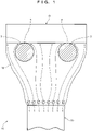
- an electron beam sterilizer 10 includes wire rods 3 and an electron beam irradiator 20.
- the wire rods 3 hold a sterilization object O.
- the position of each wire rod 3 relative to the sterilization object O is constant.
- the electron beam irradiator 20 irradiates the sterilization object O held by the wire rods 3 with an electron beam 12 over the wire rods 3.
- Each of the wire rods 3 holds the sterilization object O in a constant relative position. In other words, each of the wire rods 3 relative to the sterilization object O is constant with the sterilization object O being held. Further, to hold the sterilization object O, each of the wire rods 3 has a curved surface 4 in contact with the sterilization object O. That is, the wire rods 3 hold the sterilization object O with the curved surfaces 4 by bringing the sterilization object O in contact with such curved surfaces.
- Electrons 1 of the electron beam 12 from the electron beam irradiator 20 collide with air molecules to scatter. This causes the electrons 1 to come around to the curved surfaces 4 and reach the parts of sterilization object O in contact with the curved surfaces 4. Consequently, the sterilization object O is sterilized.
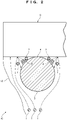
- FIG. 2 which is an enlarged view of FIG. 1 , the electrons 1 reach the sterilization object O.
- secondary electrons 2 of the sterilization object O are excited.
- the excited secondary electrons 2 are emitted from the sterilization object O.
- Such secondary electrons 2 also come around to the curved surface 4 and reach the part of sterilization object O in contact with the curved surface 4. Consequently, the sterilization object O is sterilized.
- the secondary electrons 2 emitted from the sterilization object O are not limited to the electrons excited by the electrons 1 from the electron beam irradiator 20 (hereinafter, may be referred to as primary electrons 1).
- the secondary electrons 2 include electrons, each excited by the other secondary electrons 2.
- the secondary electrons 2 emitted from the sterilization object O have lower energy than the primary electrons 1 from the electron beam irradiator 20.
- the secondary electrons 2 are thus easily absorbed by the bacteria. This enables the secondary electrons 2 easily to sterilize the bacteria. Therefore, the secondary electrons 2 have a much higher sterilization effect than the primary electrons 1.
- the wire rod 3 as a holder of the sterilization object O allows the electrons 1 (primary electrons 1) from the electron beam irradiator 20 to easily reach the sterilization object O. This is because the wire rod 3 is less likely to block the primary electrons 1. Such primary electrons 1 excite a large number of the secondary electrons 2 having a high sterilization effect. Then, the secondary electrons 2 are emitted from the sterilization object O. Additionally, the sterilization object O is held by contacting the curved surface 4 of the wire rod 3. This allows the primary electrons 1 and the secondary electrons 2 to easily come around to the part of sterilization object O in contact with the wire rod 3. As a result, a sufficient number of the primary electrons 1 and secondary electrons 2 reach the part of the sterilization object O in contact with the wire rod 3, as well as an area close to the contact part.
- the electron beam sterilizer 10 enables a sufficient number of the primary electrons 1 and secondary electrons 2 to reach the sterilization object O without being blocked by the wire rods 3. Thus, the effect of sterilization can be enhanced.
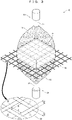
- the electron beam sterilizer 10 of Example 1 includes a mesh 30, a lower electron beam irradiator 20, and an upper electron beam irradiator 50.
- the sterilization object O is placed on the fixed mesh 30.
- the lower electron beam irradiator 20 irradiates the sterilization object O on the mesh 30 with the electron beam 12 from a lower side through the mesh 30.
- the upper electron beam irradiator 50 irradiates the sterilization object O with an electron beam 15 from un upper side.
- the mesh 30 includes longitudinal wire rods 36 and lateral wire rods 37 woven together.
- Each of the longitudinal wire rods 36 and the lateral wire rods 37 has a circular cross section.
- the curved surfaces 4 thereof come into contact with the sterilization object O to be placed on the mesh 30.
- the longitudinal wire rods 36 and the lateral wire rods 37 cross each other. That is, one of the wire rods 36 and 37 is under the other of wire rods 36 and 37 at each of the crossing parts in these wire rods 3.
- the sterilization object O is not in contact with the under parts and areas close to the under parts.
- the mesh 30 is made by weaving the longitudinal wire rods 36 and the lateral wire rods 37. Therefore, the contact parts with the sterilization object O to be placed become smaller.
- a diameter d of each of the longitudinal wire rods 36 and the lateral wire rods 37 is preferably small.
- the smaller diameter d causes the mesh 30 difficult to immovably hold the sterilization object O. This is because of the relationship between a strength of the wire rods 3 and a weight of the sterilization object O. Therefore, the diameter d is large enough to immovably hold the sterilization object O.
- an opening ratio of the mesh 30 is preferably large to enhance the effect of sterilization. However, the larger opening ratio causes the mesh 30 difficult to immovably hold the sterilization object O. This is because of the relationship between the strength of the wire rods 3 and the weight of the sterilization object O.
- the opening ratio is set to a ratio enough to immovably hold the sterilization object O.
- acceleration voltages of the lower electron beam irradiator 20 and the upper electron beam irradiator 50 are set to 80 kV to 150 kV.
- Energy of the electrons 1 (primary electrons 1) of the electron beam 12 is set to 80 keV to 150 keV. Assuming that such electrons 1 are emitted to a plate obtained by arranging the wire rods having a wire diameter of 0.03 mm side by side without gaps, these electrons 1 have low energy so as not to pass through the plate.
- the sterilization object O is sterilized by such electrons 1 coming around the wire rods 3 from the openings of the mesh 30, as well as the secondary electrons 2.
- the lower electron beam irradiator 20 and the upper electron beam irradiator 50 are nozzle type electron beam irradiators having nozzles 21 and 51, respectively.
- the nozzle type electron beam irradiators emit the electron beams 12 and 15 from tips of the nozzles 21 and 51, respectively. This allows the nozzle type electron beam irradiator to emit an electron beam having a cross section smaller than a non-nozzle type electron beam irradiator. Therefore, the nozzle type electron beam irradiators are suitably used as the lower electron beam irradiator 20 and the upper electron beam irradiator 50 for the small sterilization object O, as illustrated in FIG. 3 .
- the non-nozzle type electron beam irradiators (not shown) are suitably used as the lower electron beam irradiator 20 and the upper electron beam irradiator 50.
- the non-nozzle type electron beam irradiator emits an electron beam having a large cross section.
- the upper electron beam irradiator 50 enables sterilization of a part that cannot be sterilized by the lower electron beam irradiator 20 alone (the upper half of the sterilization object O) by the irradiation with the electron beam 15.
- the electron beam sterilizer 10 of Example 1 can obtain the same effect as the electron beam sterilizer 10 of Embodiment. Moreover, a sufficient number of the primary electrons 1 and secondary electrons 2 are hardly blocked by the mesh 30. Thus, sterilization effect can be further enhanced.
- the mesh 30 is not particularly limited as long as a material thereof is not deteriorated by the irradiation with the electron beam 12.
- the mesh 30 is preferably made of a metal such as stainless steel or titanium. Further, the mesh 30 is preferably grounded in order to prevent charging.
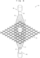
- the electron beam sterilizer 10 of Example 2 has the same configuration as the electron beam sterilizer 10 of Example 1, as illustrated in FIG. 4 . However, the electron beam sterilizer 10 of Example 2 differs from the electron beam sterilizer 10 of Example 1 in holding the sterilization object O not by placing the sterilization object O on the mesh 30 but by inserting the sterilization object O in the mesh 30.
- the mesh 30 of the electron beam sterilizer 10 in Example 2 has the openings of the mesh 30 of the electron beam sterilizer 10 in Example 1. Additionally, the openings of the mesh 30 are large enough to insert the sterilization object O therein.
- the mesh 30 holds the sterilization object O by inserting the sterilization object O in one of the openings. Therefore, only a part of the wire rods 36 and 37 of such opening then comes into contact with the sterilization object O. Therefore, the contact part of the mesh 30 and the sterilization object O is extremely small.
- the electron beam sterilizer 10 of Example 2 can obtain the same effect as the electron beam sterilizer 10 of Embodiment. Moreover, a sufficient number of the primary electrons 1 and secondary electrons 2 are hardly blocked by the mesh 30. Thus, sterilization effect can be further enhanced.
- the electron beam sterilizer 10 of Example 3 includes a brush member 35, which is also called a pin-up, instead of the mesh 30 of Examples 1 and 2, as illustrated in FIG. 5 .
- the brush member 35 includes a large number of wire rods 3 arranged in a brush shape.
- the brush member 35 holds the sterilization object O by placing the sterilization object O on tips of the wire rods 3.
- Each of the tips of the wire rods 3 has a rounded shape rather than a sharp shape, that is, the curved surface 4.
- the sterilization object O is placed on such tips of the wire rods 3. Therefore, the contact parts of the wire rods 3 and the sterilization object O are extremely small.
- the wire rods 3 extend along a direction in which the electron beam 12 is emitted from the lower electron beam irradiator 20. Consequently, the electrons 1 of the electron beam 12 are hardly blocked.
- the electron beam sterilizer 10 of Example 3 can obtain the same effect as the electron beam sterilizer 10 of Embodiment. Moreover, a sufficient number of the primary electrons 1 and secondary electrons 2 are hardly blocked by the wire rods 3. Thus, sterilization effect can be further enhanced.
- the electron beam sterilizer 10 of Example 4 holds the sterilization object O by hanging, as illustrated in FIG. 6 , unlike the electron beam sterilizers 10 described in Examples 1 to 3, which hold the sterilization object O by placing or inserting.
- Each of the wire rods 3 used for hanging has a circular cross section.
- the sterilization object O is hung to be held between the wire rods 3. Therefore, the contact parts of the wire rods 3 and the sterilization object O are extremely small.
- the sterilization object O may include a portion h hung on the wire rods 3 like a plastic bottle O in FIG. 6 .
- the sterilization object O preferably includes the portion h to be hung above the center of gravity. This allows the wire rods 3 to stably hold the sterilization object O by hanging.
- the electron beam sterilizer 10 of Example 4 can obtain the same effect as the electron beam sterilizer 10 of Embodiment. Moreover, a sufficient number of the primary electrons 1 and secondary electrons 2 are hardly blocked by the wire rods 3. Thus, sterilization effect can be further enhanced.
- the electron beam sterilizer 10 of Example 5 includes a needle member 34 and a circular member 38, as illustrated in FIG. 7 .
- the needle member 34 holds the sterilization object O by placing the sterilization object O on a tip thereof.
- the circular member 38 holds the sterilization object O by surrounding a side surface of the sterilization object O on the tip of the needle member 34.
- the needle member 34 and the circular member 38 include the wire rods 3.
- the needle member 34 is attached to an upper surface of a cylindrical member 41.
- the cylindrical member 41 defines an inner diameter of the circular member 38.
- the circular member 38 is formed in a coil shape extending upward from the cylindrical member 41.
- the circular member 38 is not limited to the coil shape.
- the circular member 38 can be any shape capable of surrounding the side surface of the sterilization object O.
- the circular member 38 may have the inner diameter equal to or less than an outer diameter of the sterilization object O.
- the sterilization object O to be surrounded is inserted into such circular member 38. Contrarily, the inner diameter may exceed the outer diameter of the sterilization object O.
- the circular member 38 with such inner diameter allows the sterilization object O inside thereof to lean against the circular member 38.
- the electron beam sterilizer 10 of Example 5 includes a rotating mechanism 60 and an elevating mechanism 70.
- the rotating mechanism 60 rotates the sterilization object O with respect to the electron beam irradiator 20 together with the wire rod 3 (the needle member 34 and the circular member 38).
- the elevating mechanism 70 moves the sterilization object O and the wire rod 3 up and down with respect to the electron beam irradiator 20.
- the tip of the nozzle 21 emitting the electron beam 12 faces the side surface of the sterilization object O at the lower end of the sterilization object O.
- the electron beam irradiator 20 irradiates the side surface of the sterilization object O over the circular member 38 with the electron beam 12 emitted from the electron beam irradiator 20.
- the electron beam irradiator 20 also irradiates a bottom surface of the sterilization object O, over the needle member 34, with the electron beam 12 coming around to the lower part of the sterilization object O.
- the circular member 38 and the needle member 34 hold the sterilization object O by inserting the sterilization object O into the circular member 38 and placing the sterilization object O on the tip of the needle member 34.
- the sterilization object O is irradiated with the electron beam 12 emitted from the electron beam irradiator 20, while the sterilization object O rotates and moves up and down together with the needle member 34 and the circular member 38.
- the ascent and descent of the sterilization object O enables sterilization, by the irradiation of the electron beam 12, of the side and bottom surfaces of the sterilization object O, as well as the other side surface (i.e., the entire surface). Additionally, the rotation of the sterilization object O enables uniform sterilization.
- the sterilization object O may move up and down, while rotating.
- the rotation and the ascent/descent may be repeated alternately. Alternately repeating the rotation and the ascent/descent can simplify control by the rotating mechanism 60 and the elevating mechanism 70.
- the ascent/descent by the elevating mechanism 70 is stopped at 2 to 6 of predetermined points.
- the rotating mechanism 60 rotates the sterilization object O 3 to 5 times (that is, 3 to 5 rotations) at each stop. More preferably, to sufficiently sterilize the bottom surface of the sterilization object O, irradiation time is increased at a height of the points where the electron beam 12 comes around to the bottom surface of the sterilization object O compared with the other heights of the points.
- the electron beam sterilizer 10 of Example 5 can obtain the same effect as the electron beam sterilizer 10 of Embodiment. Moreover, the entire surface of the sterilization object O can be sterilized.
- the electron beam sterilizer 10 of Example 6 includes the mesh 30 as the wire rod 3, as illustrated in FIG. 8 . That is, the mesh 30 is substituted for the needle member 34 and the circular member 38 of Example 5.
- the mesh 30 does not surround the side surface of the sterilization object O. This allows the electron beam sterilizer 10 to sterilize the sterilization object O having a large outer diameter such as a plastic bottle.
- the electron beam sterilizer 10 of Example 6 can obtain the same effect as the electron beam sterilizer 10 of Example 5. Moreover, the sterilization object O having a large outer diameter can also be sterilized.
- Embodiment shows two cross sections of the wire rods 3 in FIG. 1 , but not necessarily limited to the plurality of the wire rods 3.
- the single wire rod 3 may be used as long as the wire rod 3 can hold the sterilization object O with one wire.
- Embodiment shows the circular cross sections of the wire rods 3 in FIG. 1 .
- the shape is not limited to a circle as long as the part in contact with the sterilization object O is curved.
- Embodiment describes that the secondary electrons 2 are emitted from the sterilization object O.
- the secondary electrons 2 include electrons emitted from the wire rods 3.
- Embodiment and Examples 1 to 6 describe that the relative position of the wire rod 3 with respect to the sterilization object O is constant. This also includes the meaning of natural movement of the wire rod 3 and the sterilization object O by deformation due to increased temperature caused by irradiation of the electron beams 12 and 15.
- Examples 1 to 6 describe the nozzle type electron beam irradiator or the non-nozzle type electron beam irradiator as the electron beam irradiator 20.
- the electron beam irradiator 20 may be a scan type electron beam irradiator.
- the scan type electron beam irradiator emits an electron beam having a narrow width.
- Such scan type electron beam irradiator irradiates the sterilization object O, while scanning with the electron beam in a vertical direction. This can obtain the same effect as the electron beam sterilizer having the elevating mechanism 70.
- Embodiment and Examples 1 to 4 do not describe the details of what the wire rods 3, the mesh 30, and the brush member 35 are fixed to.
- the wire rods 3, the mesh 30, and the brush member 35 are fixed to at least something such as an inner wall of a box body in which the electron beams 12 and 15 are irradiated.
- Examples 1 to 4 describe that the wire rods 3 immovably hold the sterilization object O. Therefore, a drive system for moving the wire rods 3 is not required, enhancing the sterilization effect.
- Examples 1 and 2 describe that the mesh 30 includes the longitudinal wire rods 36 and the lateral wire rods 37 woven together. However, instead of such mesh 30, only the longitudinal wire rods 36 or only the lateral wire rods 37 may be arranged in parallel for the mesh 30.
- Example 4 shows that the sterilization object O is hung on the two wire rods 3 in FIG. 6 .
- the sterilization object O may include a tab h having a hole.
- the single wire rod 3 of a hook shape extending from a hanging tool 42 may be hooked in the hole of the tab h.
- Embodiment and Examples 1 to 4 does not describe the rotating mechanism 60 described in Examples 5 and 6.
- the electron beam sterilizers 10 in Examples 1 to 4 can obviously include the rotating mechanism 60.
- Embodiment and Examples 1 to 6 are merely exemplary and are not restrictive in all the aspects.
- the scope of the present invention is not indicated by the foregoing description but the claims.
- the scope of the present invention is intended to include meanings equivalent to the claims and all changes in the scope. From among the configurations described in Embodiment and Examples 1 to 6, the configurations other than those described as a first invention in "Solution to Problem" are optional and thus can be deleted and changed as appropriate.
Landscapes
- Physics & Mathematics (AREA)
- Engineering & Computer Science (AREA)
- General Engineering & Computer Science (AREA)
- High Energy & Nuclear Physics (AREA)
- Health & Medical Sciences (AREA)
- Epidemiology (AREA)
- Life Sciences & Earth Sciences (AREA)
- Animal Behavior & Ethology (AREA)
- General Health & Medical Sciences (AREA)
- Public Health (AREA)
- Veterinary Medicine (AREA)
- Apparatus For Disinfection Or Sterilisation (AREA)
Abstract
Description
- The present invention relates to an electron beam sterilizer.
- Electron beam sterilizers sterilize an object to be sterilized by irradiating the object with an electron beam. Such electron beam sterilizers have sterilized the object in a short time, and therefore, application thereof is expected in various fields. The electron beam sterilizers have been used for sterilizing objects that require high sterilization accuracy, such as food and drink containers or medical containers. For example,
Japanese Patent Laid-Open No. Hei 11-19190 - The electron beam sterilizer in
Patent Literature 1 irradiates the entire surface of each PET bottle with the electron beam, as described above. Therefore, high sterilization effect seems to be obtained. However, the electron beam sterilizer needs to move the wires in contact with the PET bottles of the objects to be sterilized relative to the PET bottles. Such relative movement may contaminate the PET bottles, causing insufficient sterilization. Therefore, reducing the risk of contamination is highly desired particularly in the medical field where extremely high accuracy of sterilization is required. - An object of the present invention is to provide an electron beam sterilizer capable of enhancing the effect of sterilization.
- In order to solve the problem, an electron beam sterilizer according to a first invention includes:
- at least one wire rod configured to hold a sterilization object, the wire rod being in a constant relative position with respect to the sterilization object; and
- an electron beam irradiator configured to irradiate the sterilization object held by the wire rod with an electron beam over the wire rod,
- wherein the wire rod includes a curved surface in contact with the sterilization object to hold, and
- electrons of the electron beam from the electron beam irradiator, and secondary electrons excited by the electrons come around to the curved surface in contact with the sterilization object to sterilize the sterilization object.
- An electron beam sterilizer according to a second invention, in the electron beam sterilizer according to the first invention, further includes a mesh configured to hold the sterilization object by placing the sterilization object on the mesh, or inserting the sterilization object in the mesh,
wherein the mesh includes the wire rod woven together. - An electron beam sterilizer according to a third invention, in the electron beam sterilizer according to the first invention, further includes a brush member configured to hold the sterilization object by placing the sterilization object on the brush member,
wherein the brush member includes the wire rod extending along a direction in which the electron beam is emitted from the electron beam irradiator. - An electron beam sterilizer according to a fourth invention, in the electron beam sterilizer according to the first invention, wherein the wire rod holds the sterilization object by hanging the sterilization object.
- An electron beam sterilizer according to a fifth invention, in the electron beam sterilizer according to the first invention, further includes:
- a needle member configured to hold the sterilization object by placing the sterilization object on a tip of the needle member; and
- a circular member configured to hold the sterilization object by surrounding a side surface of the sterilization object on the tip of the needle member,
- wherein the needle member and the circular member include the wire rod.
- An electron beam sterilizer according to a sixth invention, in the electron beam sterilizer according to any one of the first to fifth inventions, further includes a rotating mechanism configured to rotate the sterilization object and the wire rod with respect to the electron beam irradiator.
- An electron beam sterilizer according to a seventh invention, in the electron beam sterilizer according to the sixth invention, wherein the electron beam irradiator irradiates the side surface of the sterilization object with the electron beam.
- An electron beam sterilizer according to an eighth invention, in the electron beam sterilizer according to the seventh invention, further includes an elevating mechanism configured to move the sterilization object and the wire rod up and down with respect to the electron beam irradiator.
- The above electron beam sterilizer can enhance the effect of sterilization. This is because a sufficient number of electrons reach the object to be sterilized without being blocked by the wire rod.
-
- [
FIG. 1] FIG. 1 is a schematic cross-sectional view illustrating an electron beam sterilizer according to Embodiment of the present invention. - [
FIG. 2] FIG. 2 is a schematic enlarged sectional view of the electron beam sterilizer. - [
FIG. 3] FIG. 3 is a perspective view of an electron beam sterilizer according to Example 1 of the present invention. - [
FIG. 4] FIG. 4 is a perspective view of an electron beam sterilizer according to Example 2 of the present invention. - [
FIG. 5] FIG. 5 is a side view of an electron beam sterilizer according to Example 3 of the present invention. - [
FIG. 6] FIG. 6 is a perspective view of an electron beam sterilizer according to Example 4 of the present invention. - [
FIG. 7] FIG. 7 is a perspective view of an electron beam sterilizer according to Example 5 of the present invention. - [
FIG. 8] FIG. 8 is a perspective view of an electron beam sterilizer according to Example 6 of the present invention. - [
FIG. 9] FIG. 9 is a perspective view illustrating a modification of the electron beam sterilizer according to Example 4 of the present invention. - An electron beam sterilizer according to Embodiment of the present invention will be described below in accordance with
FIGS. 1 and2 . The electron beam sterilizer sterilizes an object to be sterilized by electron beam irradiation. - As illustrated in
FIG. 1 , anelectron beam sterilizer 10 includeswire rods 3 and anelectron beam irradiator 20. Thewire rods 3 hold a sterilization object O. The position of eachwire rod 3 relative to the sterilization object O is constant. Theelectron beam irradiator 20 irradiates the sterilization object O held by thewire rods 3 with anelectron beam 12 over thewire rods 3. - Each of the
wire rods 3 holds the sterilization object O in a constant relative position. In other words, each of thewire rods 3 relative to the sterilization object O is constant with the sterilization object O being held. Further, to hold the sterilization object O, each of thewire rods 3 has acurved surface 4 in contact with the sterilization object O. That is, thewire rods 3 hold the sterilization object O with thecurved surfaces 4 by bringing the sterilization object O in contact with such curved surfaces. -
Electrons 1 of theelectron beam 12 from theelectron beam irradiator 20 collide with air molecules to scatter. This causes theelectrons 1 to come around to thecurved surfaces 4 and reach the parts of sterilization object O in contact with thecurved surfaces 4. Consequently, the sterilization object O is sterilized. Further, as illustrated inFIG. 2 , which is an enlarged view ofFIG. 1 , theelectrons 1 reach the sterilization object O. Then,secondary electrons 2 of the sterilization object O are excited. The excitedsecondary electrons 2 are emitted from the sterilization object O. Suchsecondary electrons 2 also come around to thecurved surface 4 and reach the part of sterilization object O in contact with thecurved surface 4. Consequently, the sterilization object O is sterilized. Thesecondary electrons 2 emitted from the sterilization object O are not limited to the electrons excited by theelectrons 1 from the electron beam irradiator 20 (hereinafter, may be referred to as primary electrons 1). Thesecondary electrons 2 include electrons, each excited by the othersecondary electrons 2. Thesecondary electrons 2 emitted from the sterilization object O have lower energy than theprimary electrons 1 from theelectron beam irradiator 20. Thesecondary electrons 2 are thus easily absorbed by the bacteria. This enables thesecondary electrons 2 easily to sterilize the bacteria. Therefore, thesecondary electrons 2 have a much higher sterilization effect than theprimary electrons 1. - The
wire rod 3 as a holder of the sterilization object O allows the electrons 1 (primary electrons 1) from theelectron beam irradiator 20 to easily reach the sterilization object O. This is because thewire rod 3 is less likely to block theprimary electrons 1. Suchprimary electrons 1 excite a large number of thesecondary electrons 2 having a high sterilization effect. Then, thesecondary electrons 2 are emitted from the sterilization object O. Additionally, the sterilization object O is held by contacting thecurved surface 4 of thewire rod 3. This allows theprimary electrons 1 and thesecondary electrons 2 to easily come around to the part of sterilization object O in contact with thewire rod 3. As a result, a sufficient number of theprimary electrons 1 andsecondary electrons 2 reach the part of the sterilization object O in contact with thewire rod 3, as well as an area close to the contact part. - As described above, the
electron beam sterilizer 10 enables a sufficient number of theprimary electrons 1 andsecondary electrons 2 to reach the sterilization object O without being blocked by thewire rods 3. Thus, the effect of sterilization can be enhanced. - Hereinafter, an
electron beam sterilizer 10, according to each of Examples 1 to 6 more specifically showing Embodiment, will be described with reference to the drawings. In Examples 1 to 6, the configurations omitted in Embodiment will be focused on. The same configurations in Embodiment will be designated by the same reference numerals and the description thereof will be omitted. - As illustrated in
FIG. 3 , theelectron beam sterilizer 10 of Example 1 includes amesh 30, a lowerelectron beam irradiator 20, and an upperelectron beam irradiator 50. The sterilization object O is placed on the fixedmesh 30. The lowerelectron beam irradiator 20 irradiates the sterilization object O on themesh 30 with theelectron beam 12 from a lower side through themesh 30. The upperelectron beam irradiator 50 irradiates the sterilization object O with anelectron beam 15 from un upper side. - The
mesh 30 includeslongitudinal wire rods 36 andlateral wire rods 37 woven together. Each of thelongitudinal wire rods 36 and thelateral wire rods 37 has a circular cross section. Thecurved surfaces 4 thereof come into contact with the sterilization object O to be placed on themesh 30. Additionally, thelongitudinal wire rods 36 and thelateral wire rods 37 cross each other. That is, one of thewire rods wire rods wire rods 3. The sterilization object O is not in contact with the under parts and areas close to the under parts. In other words, themesh 30 is made by weaving thelongitudinal wire rods 36 and thelateral wire rods 37. Therefore, the contact parts with the sterilization object O to be placed become smaller. - To enhance the effect of sterilization, a diameter d of each of the
longitudinal wire rods 36 and thelateral wire rods 37 is preferably small. However, the smaller diameter d causes themesh 30 difficult to immovably hold the sterilization object O. This is because of the relationship between a strength of thewire rods 3 and a weight of the sterilization object O. Therefore, the diameter d is large enough to immovably hold the sterilization object O. Similarly, an opening ratio of themesh 30 is preferably large to enhance the effect of sterilization. However, the larger opening ratio causes themesh 30 difficult to immovably hold the sterilization object O. This is because of the relationship between the strength of thewire rods 3 and the weight of the sterilization object O. Therefore, the opening ratio is set to a ratio enough to immovably hold the sterilization object O. Note that the opening ratio ε is calculated from the following equation (1).
the opening ratio is ε, the opening is A, and the diameter of each of thewire rods - Here, acceleration voltages of the lower
electron beam irradiator 20 and the upperelectron beam irradiator 50 are set to 80 kV to 150 kV. Energy of the electrons 1 (primary electrons 1) of theelectron beam 12 is set to 80 keV to 150 keV. Assuming thatsuch electrons 1 are emitted to a plate obtained by arranging the wire rods having a wire diameter of 0.03 mm side by side without gaps, theseelectrons 1 have low energy so as not to pass through the plate. The sterilization object O is sterilized bysuch electrons 1 coming around thewire rods 3 from the openings of themesh 30, as well as thesecondary electrons 2. - The lower
electron beam irradiator 20 and the upperelectron beam irradiator 50 are nozzle type electron beamirradiators having nozzles electron beams nozzles electron beam irradiator 20 and the upperelectron beam irradiator 50 for the small sterilization object O, as illustrated inFIG. 3 . However, for the larger sterilization object O, the non-nozzle type electron beam irradiators (not shown) are suitably used as the lowerelectron beam irradiator 20 and the upperelectron beam irradiator 50. This is because the non-nozzle type electron beam irradiator emits an electron beam having a large cross section. In suchelectron beam sterilizer 10, the upperelectron beam irradiator 50 enables sterilization of a part that cannot be sterilized by the lowerelectron beam irradiator 20 alone (the upper half of the sterilization object O) by the irradiation with theelectron beam 15. - The
electron beam sterilizer 10 of Example 1 can obtain the same effect as theelectron beam sterilizer 10 of Embodiment. Moreover, a sufficient number of theprimary electrons 1 andsecondary electrons 2 are hardly blocked by themesh 30. Thus, sterilization effect can be further enhanced. - Here, the
mesh 30 is not particularly limited as long as a material thereof is not deteriorated by the irradiation with theelectron beam 12. Themesh 30 is preferably made of a metal such as stainless steel or titanium. Further, themesh 30 is preferably grounded in order to prevent charging. - The
electron beam sterilizer 10 of Example 2 has the same configuration as theelectron beam sterilizer 10 of Example 1, as illustrated inFIG. 4 . However, theelectron beam sterilizer 10 of Example 2 differs from theelectron beam sterilizer 10 of Example 1 in holding the sterilization object O not by placing the sterilization object O on themesh 30 but by inserting the sterilization object O in themesh 30. - The
mesh 30 of theelectron beam sterilizer 10 in Example 2 has the openings of themesh 30 of theelectron beam sterilizer 10 in Example 1. Additionally, the openings of themesh 30 are large enough to insert the sterilization object O therein. - The
mesh 30 holds the sterilization object O by inserting the sterilization object O in one of the openings. Therefore, only a part of thewire rods mesh 30 and the sterilization object O is extremely small. - The
electron beam sterilizer 10 of Example 2 can obtain the same effect as theelectron beam sterilizer 10 of Embodiment. Moreover, a sufficient number of theprimary electrons 1 andsecondary electrons 2 are hardly blocked by themesh 30. Thus, sterilization effect can be further enhanced. - The
electron beam sterilizer 10 of Example 3 includes abrush member 35, which is also called a pin-up, instead of themesh 30 of Examples 1 and 2, as illustrated inFIG. 5 . - The
brush member 35 includes a large number ofwire rods 3 arranged in a brush shape. Thebrush member 35 holds the sterilization object O by placing the sterilization object O on tips of thewire rods 3. Each of the tips of thewire rods 3 has a rounded shape rather than a sharp shape, that is, thecurved surface 4. The sterilization object O is placed on such tips of thewire rods 3. Therefore, the contact parts of thewire rods 3 and the sterilization object O are extremely small. Additionally, thewire rods 3 extend along a direction in which theelectron beam 12 is emitted from the lowerelectron beam irradiator 20. Consequently, theelectrons 1 of theelectron beam 12 are hardly blocked. - The
electron beam sterilizer 10 of Example 3 can obtain the same effect as theelectron beam sterilizer 10 of Embodiment. Moreover, a sufficient number of theprimary electrons 1 andsecondary electrons 2 are hardly blocked by thewire rods 3. Thus, sterilization effect can be further enhanced. - The
electron beam sterilizer 10 of Example 4 holds the sterilization object O by hanging, as illustrated inFIG. 6 , unlike theelectron beam sterilizers 10 described in Examples 1 to 3, which hold the sterilization object O by placing or inserting. - Each of the
wire rods 3 used for hanging has a circular cross section. The sterilization object O is hung to be held between thewire rods 3. Therefore, the contact parts of thewire rods 3 and the sterilization object O are extremely small. Further, the sterilization object O may include a portion h hung on thewire rods 3 like a plastic bottle O inFIG. 6 . The sterilization object O preferably includes the portion h to be hung above the center of gravity. This allows thewire rods 3 to stably hold the sterilization object O by hanging. - The
electron beam sterilizer 10 of Example 4 can obtain the same effect as theelectron beam sterilizer 10 of Embodiment. Moreover, a sufficient number of theprimary electrons 1 andsecondary electrons 2 are hardly blocked by thewire rods 3. Thus, sterilization effect can be further enhanced. - The
electron beam sterilizer 10 of Example 5 includes a needle member 34 and a circular member 38, as illustrated inFIG. 7 . The needle member 34 holds the sterilization object O by placing the sterilization object O on a tip thereof. The circular member 38 holds the sterilization object O by surrounding a side surface of the sterilization object O on the tip of the needle member 34. The needle member 34 and the circular member 38 include thewire rods 3. - The needle member 34 is attached to an upper surface of a
cylindrical member 41. Thecylindrical member 41 defines an inner diameter of the circular member 38. The circular member 38 is formed in a coil shape extending upward from thecylindrical member 41. However, the circular member 38 is not limited to the coil shape. The circular member 38 can be any shape capable of surrounding the side surface of the sterilization object O. The circular member 38 may have the inner diameter equal to or less than an outer diameter of the sterilization object O. The sterilization object O to be surrounded is inserted into such circular member 38. Contrarily, the inner diameter may exceed the outer diameter of the sterilization object O. The circular member 38 with such inner diameter allows the sterilization object O inside thereof to lean against the circular member 38. - The
electron beam sterilizer 10 of Example 5 includes arotating mechanism 60 and an elevatingmechanism 70. Therotating mechanism 60 rotates the sterilization object O with respect to theelectron beam irradiator 20 together with the wire rod 3 (the needle member 34 and the circular member 38). The elevatingmechanism 70 moves the sterilization object O and thewire rod 3 up and down with respect to theelectron beam irradiator 20. - In such
electron beam irradiator 20, the tip of thenozzle 21 emitting theelectron beam 12 faces the side surface of the sterilization object O at the lower end of the sterilization object O. Theelectron beam irradiator 20 irradiates the side surface of the sterilization object O over the circular member 38 with theelectron beam 12 emitted from theelectron beam irradiator 20. Theelectron beam irradiator 20 also irradiates a bottom surface of the sterilization object O, over the needle member 34, with theelectron beam 12 coming around to the lower part of the sterilization object O. - Next, a method of using the
electron beam sterilizer 10 of Example 5 will be described. - First, the circular member 38 and the needle member 34 hold the sterilization object O by inserting the sterilization object O into the circular member 38 and placing the sterilization object O on the tip of the needle member 34.
- Then, the sterilization object O is irradiated with the
electron beam 12 emitted from theelectron beam irradiator 20, while the sterilization object O rotates and moves up and down together with the needle member 34 and the circular member 38. The ascent and descent of the sterilization object O enables sterilization, by the irradiation of theelectron beam 12, of the side and bottom surfaces of the sterilization object O, as well as the other side surface (i.e., the entire surface). Additionally, the rotation of the sterilization object O enables uniform sterilization. - Regarding the rotation and the ascent/descent, the sterilization object O may move up and down, while rotating. The rotation and the ascent/descent may be repeated alternately. Alternately repeating the rotation and the ascent/descent can simplify control by the rotating
mechanism 60 and the elevatingmechanism 70. Preferably, the ascent/descent by the elevatingmechanism 70 is stopped at 2 to 6 of predetermined points. Then, the rotatingmechanism 60 rotates thesterilization object O 3 to 5 times (that is, 3 to 5 rotations) at each stop. More preferably, to sufficiently sterilize the bottom surface of the sterilization object O, irradiation time is increased at a height of the points where theelectron beam 12 comes around to the bottom surface of the sterilization object O compared with the other heights of the points. - The
electron beam sterilizer 10 of Example 5 can obtain the same effect as theelectron beam sterilizer 10 of Embodiment. Moreover, the entire surface of the sterilization object O can be sterilized. - The
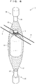
electron beam sterilizer 10 of Example 6 includes themesh 30 as thewire rod 3, as illustrated inFIG. 8 . That is, themesh 30 is substituted for the needle member 34 and the circular member 38 of Example 5. - The
mesh 30 does not surround the side surface of the sterilization object O. This allows theelectron beam sterilizer 10 to sterilize the sterilization object O having a large outer diameter such as a plastic bottle. - The
electron beam sterilizer 10 of Example 6 can obtain the same effect as theelectron beam sterilizer 10 of Example 5. Moreover, the sterilization object O having a large outer diameter can also be sterilized. - Here, Embodiment shows two cross sections of the
wire rods 3 inFIG. 1 , but not necessarily limited to the plurality of thewire rods 3. Thesingle wire rod 3 may be used as long as thewire rod 3 can hold the sterilization object O with one wire. - Further, Embodiment shows the circular cross sections of the
wire rods 3 inFIG. 1 . However, the shape is not limited to a circle as long as the part in contact with the sterilization object O is curved. - Furthermore, Embodiment describes that the
secondary electrons 2 are emitted from the sterilization object O. However, thesecondary electrons 2 include electrons emitted from thewire rods 3. - Furthermore, Embodiment and Examples 1 to 6 describe that the relative position of the
wire rod 3 with respect to the sterilization object O is constant. This also includes the meaning of natural movement of thewire rod 3 and the sterilization object O by deformation due to increased temperature caused by irradiation of theelectron beams - Furthermore, Examples 1 to 6 describe the nozzle type electron beam irradiator or the non-nozzle type electron beam irradiator as the
electron beam irradiator 20. Theelectron beam irradiator 20 may be a scan type electron beam irradiator. The scan type electron beam irradiator emits an electron beam having a narrow width. Such scan type electron beam irradiator irradiates the sterilization object O, while scanning with the electron beam in a vertical direction. This can obtain the same effect as the electron beam sterilizer having the elevatingmechanism 70. - Furthermore, Embodiment and Examples 1 to 4 do not describe the details of what the
wire rods 3, themesh 30, and thebrush member 35 are fixed to. Thewire rods 3, themesh 30, and thebrush member 35 are fixed to at least something such as an inner wall of a box body in which theelectron beams - Furthermore, Examples 1 to 4 describe that the
wire rods 3 immovably hold the sterilization object O. Therefore, a drive system for moving thewire rods 3 is not required, enhancing the sterilization effect. - Furthermore, Examples 1 and 2 describe that the
mesh 30 includes thelongitudinal wire rods 36 and thelateral wire rods 37 woven together. However, instead ofsuch mesh 30, only thelongitudinal wire rods 36 or only thelateral wire rods 37 may be arranged in parallel for themesh 30. - Furthermore, Example 4 shows that the sterilization object O is hung on the two
wire rods 3 inFIG. 6 . However, as illustrated inFIG. 9 , the sterilization object O may include a tab h having a hole. Thesingle wire rod 3 of a hook shape extending from a hangingtool 42 may be hooked in the hole of the tab h. - Furthermore, Embodiment and Examples 1 to 4 does not describe the
rotating mechanism 60 described in Examples 5 and 6. However, theelectron beam sterilizers 10 in Examples 1 to 4 can obviously include therotating mechanism 60. - Furthermore, Embodiment and Examples 1 to 6 are merely exemplary and are not restrictive in all the aspects. The scope of the present invention is not indicated by the foregoing description but the claims. The scope of the present invention is intended to include meanings equivalent to the claims and all changes in the scope. From among the configurations described in Embodiment and Examples 1 to 6, the configurations other than those described as a first invention in "Solution to Problem" are optional and thus can be deleted and changed as appropriate.
Claims (8)
- An electron beam sterilizer comprising:at least one wire rod configured to hold a sterilization object, the wire rod being in a constant relative position with respect to the sterilization object; andan electron beam irradiator configured to irradiate the sterilization object held by the wire rod with an electron beam over the wire rod,wherein the wire rod includes a curved surface in contact with the sterilization object to hold, andelectrons of the electron beam from the electron beam irradiator, and secondary electrons excited by the electrons come around to the curved surface in contact with the sterilization object to sterilize the sterilization object.
- The electron beam sterilizer according to claim 1, further comprising a mesh configured to hold the sterilization object by placing the sterilization object on the mesh, or inserting the sterilization object in the mesh,
wherein the mesh includes the wire rod woven together. - The electron beam sterilizer according to claim 1, further comprising a brush member configured to hold the sterilization object by placing the sterilization object on the brush member,
wherein the brush member includes the wire rod extending along a direction in which the electron beam is emitted from the electron beam irradiator. - The electron beam sterilizer according to claim 1, wherein the wire rod holds the sterilization object by hanging the sterilization object.
- The electron beam sterilizer according to claim 1, further comprising:a needle member configured to hold the sterilization object by placing the sterilization object on a tip of the needle member; anda circular member configured to hold the sterilization object by surrounding a side surface of the sterilization object on the tip of the needle member,wherein the needle member and the circular member include the wire rod.
- The electron beam sterilizer according to any one of claims 1 to 5, further comprising a rotating mechanism configured to rotate the sterilization object and the wire rod with respect to the electron beam irradiator.
- The electron beam sterilizer according to claim 6, wherein the electron beam irradiator irradiates the side surface of the sterilization object with the electron beam.
- The electron beam sterilizer according to claim 7, further comprising an elevating mechanism configured to move the sterilization object and the wire rod up and down with respect to the electron beam irradiator.
Applications Claiming Priority (2)
| Application Number | Priority Date | Filing Date | Title |
|---|---|---|---|
| JP2019099851 | 2019-05-29 | ||
| PCT/JP2020/021127 WO2020241758A1 (en) | 2019-05-29 | 2020-05-28 | Electron beam sterilization device |
Publications (2)
| Publication Number | Publication Date |
|---|---|
| EP3974001A1 true EP3974001A1 (en) | 2022-03-30 |
| EP3974001A4 EP3974001A4 (en) | 2023-10-04 |
Family
ID=73553789
Family Applications (1)
| Application Number | Title | Priority Date | Filing Date |
|---|---|---|---|
| EP20813403.1A Withdrawn EP3974001A4 (en) | 2019-05-29 | 2020-05-28 | Electron beam sterilization device |
Country Status (3)
| Country | Link |
|---|---|
| EP (1) | EP3974001A4 (en) |
| JP (1) | JPWO2020241758A1 (en) |
| WO (1) | WO2020241758A1 (en) |
Cited By (1)
| Publication number | Priority date | Publication date | Assignee | Title |
|---|---|---|---|---|
| EP3865412A4 (en) * | 2018-10-11 | 2022-11-16 | Suntory Holdings Limited | STERILIZATION DEVICE AND STERILIZATION METHOD |
Families Citing this family (1)
| Publication number | Priority date | Publication date | Assignee | Title |
|---|---|---|---|---|
| EP4301416A1 (en) | 2021-03-05 | 2024-01-10 | NextKidney SA | Stable storage of enzymes |
Family Cites Families (8)
| Publication number | Priority date | Publication date | Assignee | Title |
|---|---|---|---|---|
| JPH1119190A (en) * | 1997-07-02 | 1999-01-26 | Iwasaki Electric Co Ltd | Electron beam sterilization method and electron beam sterilizer |
| JP2003014900A (en) * | 2001-06-29 | 2003-01-15 | Iwasaki Electric Co Ltd | Electron beam irradiation device |
| JP2003161800A (en) * | 2001-11-28 | 2003-06-06 | Mitsubishi Electric Corp | Electron or X-ray irradiation system |
| JP2004067233A (en) * | 2002-08-09 | 2004-03-04 | Mitsubishi Heavy Ind Ltd | Sterilization apparatus and system |
| WO2007046213A1 (en) * | 2005-10-18 | 2007-04-26 | Japan Ae Power Systems Corporation | Electron beam application method, electron beam application device, electron beam application device for opening-equipped vessel |
| WO2013154782A1 (en) * | 2012-04-12 | 2013-10-17 | Electronworks Holdings Llc | Low energy electron sterilization |
| JP6697911B2 (en) * | 2016-03-18 | 2020-05-27 | 日立造船株式会社 | Electron beam sterilization equipment |
| JP6694797B2 (en) * | 2016-10-27 | 2020-05-20 | 日立造船株式会社 | Electron beam sterilization equipment |
-
2020
- 2020-05-28 JP JP2021522862A patent/JPWO2020241758A1/ja active Pending
- 2020-05-28 EP EP20813403.1A patent/EP3974001A4/en not_active Withdrawn
- 2020-05-28 WO PCT/JP2020/021127 patent/WO2020241758A1/en not_active Ceased
Cited By (1)
| Publication number | Priority date | Publication date | Assignee | Title |
|---|---|---|---|---|
| EP3865412A4 (en) * | 2018-10-11 | 2022-11-16 | Suntory Holdings Limited | STERILIZATION DEVICE AND STERILIZATION METHOD |
Also Published As
| Publication number | Publication date |
|---|---|
| EP3974001A4 (en) | 2023-10-04 |
| JPWO2020241758A1 (en) | 2020-12-03 |
| WO2020241758A1 (en) | 2020-12-03 |
Similar Documents
| Publication | Publication Date | Title |
|---|---|---|
| KR101621830B1 (en) | Apparatus and method for sterilizing vessel with electron beam | |
| US9155807B2 (en) | Method and apparatus for the sterilization of containers | |
| EP1991993B2 (en) | Electron beam emitter | |
| EP2269943B1 (en) | Method and device for sterilizing and filling resin vessels | |
| US8729499B2 (en) | Device for internal and external sterilisation of plastic containers by means of charge carrier beams | |
| US20110012030A1 (en) | Ebeam sterilization apparatus | |
| EP1849746A8 (en) | Apparatus and method for sterilization of vessels | |
| CN102046209A (en) | Device for sterilizing containers by way of charge carriers | |
| JP2006518689A (en) | Apparatus and method for filling a container with a drug | |
| JP2013151327A (en) | Apparatus and method of sterilizing inner wall of container with reflector apparatus | |
| CN104857539A (en) | Method And Device For Sterilising Containers | |
| JP5645562B2 (en) | Electron beam sterilizer | |
| WO2020241758A1 (en) | Electron beam sterilization device | |
| JP2011520713A (en) | Device for supplying container lids | |
| EP2292515A1 (en) | Electron beam irradiation device for aperture vessel | |
| JP4715018B2 (en) | Container sterilization method and sterilizer | |
| TW202103739A (en) | Container for sterilising flexible bags and filling/sterilisation method thereof | |
| JP2020169058A (en) | Equipment and methods for sterilizing container lids | |
| DE102009008633B4 (en) | Device for sterilizing containers | |
| US9358312B2 (en) | Method and apparatus for the sterilization of containers with cleaning of a radiation outlet window | |
| JP2018503565A (en) | Electron beam sterilization system having an external sterilization emitter that moves relative to the object to be sterilized | |
| EP4218836A1 (en) | Continuous decontamination device | |
| JP2003014900A (en) | Electron beam irradiation device | |
| JP4380216B2 (en) | Electron beam sterilizer and sterilization system | |
| JP2017518935A (en) | Method and system for decontamination of container cap or neck by pulsed electron impact |
Legal Events
| Date | Code | Title | Description |
|---|---|---|---|
| STAA | Information on the status of an ep patent application or granted ep patent |
Free format text: STATUS: THE INTERNATIONAL PUBLICATION HAS BEEN MADE |
|
| PUAI | Public reference made under article 153(3) epc to a published international application that has entered the european phase |
Free format text: ORIGINAL CODE: 0009012 |
|
| STAA | Information on the status of an ep patent application or granted ep patent |
Free format text: STATUS: REQUEST FOR EXAMINATION WAS MADE |
|
| 17P | Request for examination filed |
Effective date: 20211223 |
|
| AK | Designated contracting states |
Kind code of ref document: A1 Designated state(s): AL AT BE BG CH CY CZ DE DK EE ES FI FR GB GR HR HU IE IS IT LI LT LU LV MC MK MT NL NO PL PT RO RS SE SI SK SM TR |
|
| DAV | Request for validation of the european patent (deleted) | ||
| DAX | Request for extension of the european patent (deleted) | ||
| RIC1 | Information provided on ipc code assigned before grant |
Ipc: G21K 5/10 20060101ALI20230526BHEP Ipc: G21K 5/08 20060101ALI20230526BHEP Ipc: G21K 5/02 20060101ALI20230526BHEP Ipc: A61L 2/08 20060101AFI20230526BHEP |
|
| A4 | Supplementary search report drawn up and despatched |
Effective date: 20230905 |
|
| RIC1 | Information provided on ipc code assigned before grant |
Ipc: G21K 5/10 20060101ALI20230830BHEP Ipc: G21K 5/08 20060101ALI20230830BHEP Ipc: G21K 5/02 20060101ALI20230830BHEP Ipc: A61L 2/08 20060101AFI20230830BHEP |
|
| STAA | Information on the status of an ep patent application or granted ep patent |
Free format text: STATUS: THE APPLICATION HAS BEEN WITHDRAWN |
|
| 18W | Application withdrawn |
Effective date: 20231204 |