EP3973886B1 - Blasenüberwachungsvorrichtung und verfahren unter verwendung eines ultraschallsensors - Google Patents
Blasenüberwachungsvorrichtung und verfahren unter verwendung eines ultraschallsensors Download PDFInfo
- Publication number
- EP3973886B1 EP3973886B1 EP20809992.9A EP20809992A EP3973886B1 EP 3973886 B1 EP3973886 B1 EP 3973886B1 EP 20809992 A EP20809992 A EP 20809992A EP 3973886 B1 EP3973886 B1 EP 3973886B1
- Authority
- EP
- European Patent Office
- Prior art keywords
- bladder
- front wall
- distance
- volume
- information
- Prior art date
- Legal status (The legal status is an assumption and is not a legal conclusion. Google has not performed a legal analysis and makes no representation as to the accuracy of the status listed.)
- Active
Links
Images


Classifications
-
- A—HUMAN NECESSITIES
- A61—MEDICAL OR VETERINARY SCIENCE; HYGIENE
- A61B—DIAGNOSIS; SURGERY; IDENTIFICATION
- A61B8/00—Diagnosis using ultrasonic, sonic or infrasonic waves
- A61B8/48—Diagnostic techniques
-
- A—HUMAN NECESSITIES
- A61—MEDICAL OR VETERINARY SCIENCE; HYGIENE
- A61B—DIAGNOSIS; SURGERY; IDENTIFICATION
- A61B8/00—Diagnosis using ultrasonic, sonic or infrasonic waves
- A61B8/08—Clinical applications
- A61B8/0833—Clinical applications involving detecting or locating foreign bodies or organic structures
-
- A—HUMAN NECESSITIES
- A61—MEDICAL OR VETERINARY SCIENCE; HYGIENE
- A61B—DIAGNOSIS; SURGERY; IDENTIFICATION
- A61B8/00—Diagnosis using ultrasonic, sonic or infrasonic waves
- A61B8/08—Clinical applications
- A61B8/0858—Clinical applications involving measuring tissue layers, e.g. skin, interfaces
-
- A—HUMAN NECESSITIES
- A61—MEDICAL OR VETERINARY SCIENCE; HYGIENE
- A61B—DIAGNOSIS; SURGERY; IDENTIFICATION
- A61B8/00—Diagnosis using ultrasonic, sonic or infrasonic waves
- A61B8/44—Constructional features of the ultrasonic, sonic or infrasonic diagnostic device
- A61B8/4444—Constructional features of the ultrasonic, sonic or infrasonic diagnostic device related to the probe
- A61B8/4455—Features of the external shape of the probe, e.g. ergonomic aspects
-
- A—HUMAN NECESSITIES
- A61—MEDICAL OR VETERINARY SCIENCE; HYGIENE
- A61B—DIAGNOSIS; SURGERY; IDENTIFICATION
- A61B8/00—Diagnosis using ultrasonic, sonic or infrasonic waves
- A61B8/44—Constructional features of the ultrasonic, sonic or infrasonic diagnostic device
- A61B8/4483—Constructional features of the ultrasonic, sonic or infrasonic diagnostic device characterised by features of the ultrasound transducer
- A61B8/4488—Constructional features of the ultrasonic, sonic or infrasonic diagnostic device characterised by features of the ultrasound transducer the transducer being a phased array
-
- A—HUMAN NECESSITIES
- A61—MEDICAL OR VETERINARY SCIENCE; HYGIENE
- A61B—DIAGNOSIS; SURGERY; IDENTIFICATION
- A61B8/00—Diagnosis using ultrasonic, sonic or infrasonic waves
- A61B8/46—Ultrasonic, sonic or infrasonic diagnostic devices with special arrangements for interfacing with the operator or the patient
-
- A—HUMAN NECESSITIES
- A61—MEDICAL OR VETERINARY SCIENCE; HYGIENE
- A61B—DIAGNOSIS; SURGERY; IDENTIFICATION
- A61B8/00—Diagnosis using ultrasonic, sonic or infrasonic waves
- A61B8/52—Devices using data or image processing specially adapted for diagnosis using ultrasonic, sonic or infrasonic waves
- A61B8/5207—Devices using data or image processing specially adapted for diagnosis using ultrasonic, sonic or infrasonic waves involving processing of raw data to produce diagnostic data, e.g. for generating an image
-
- A—HUMAN NECESSITIES
- A61—MEDICAL OR VETERINARY SCIENCE; HYGIENE
- A61B—DIAGNOSIS; SURGERY; IDENTIFICATION
- A61B8/00—Diagnosis using ultrasonic, sonic or infrasonic waves
- A61B8/52—Devices using data or image processing specially adapted for diagnosis using ultrasonic, sonic or infrasonic waves
- A61B8/5215—Devices using data or image processing specially adapted for diagnosis using ultrasonic, sonic or infrasonic waves involving processing of medical diagnostic data
- A61B8/5223—Devices using data or image processing specially adapted for diagnosis using ultrasonic, sonic or infrasonic waves involving processing of medical diagnostic data for extracting a diagnostic or physiological parameter from medical diagnostic data
-
- A—HUMAN NECESSITIES
- A61—MEDICAL OR VETERINARY SCIENCE; HYGIENE
- A61B—DIAGNOSIS; SURGERY; IDENTIFICATION
- A61B8/00—Diagnosis using ultrasonic, sonic or infrasonic waves
- A61B8/54—Control of the diagnostic device
Definitions
- the present disclosure relates to a bladder monitoring apparatus and method using an ultrasonic sensor and, more specifically, to a bladder monitoring apparatus and method for calculating the volume of a bladder by using an ultrasonic sensor.
- the technical task to be solved by the present disclosure is to provide an apparatus and a method by which the volume of the bladder can be monitored by measuring only a front wall of a bladder by using an ultrasonic sensor.
- An apparatus includes: an ultrasonic sensor module including an ultrasonic sensor configured to transmit an ultrasonic wave toward a front wall of a bladder and receive the ultrasonic wave returning after being reflected by the front wall of the bladder; a control module configured to measure a passage time interval from a time point at which the ultrasonic sensor transmits the ultrasonic wave to a time point at which the ultrasonic sensor receives the ultrasonic wave returning after being reflected by the front wall of the bladder, calculate distance information from the passage time interval and a speed of the ultrasonic wave, and calculate a volume of the bladder from the distance information and configuration information input from the outside; and an output module configured to output the bladder volume calculated by the control module.
- the ultrasonic sensor module may include multiple ultrasonic sensors, and the multiple ultrasonic sensors may be arranged according to a two-dimensional arrangement and configured to transmit ultrasonic waves according to a pre-configured time period.
- control module may include: an input unit configured to receive configuration information relating to the bladder volume from the outside; a calculation unit configured to calculate the bladder volume from the configuration information and the passage time interval; and a storage unit configured to store information generated from the input unit or the calculation unit.
- the configuration information includes: a bladder volume limit indicating the bladder volume of a time point at which the bladder is filled with a designated volume of urine; a front wall distance limit indicating a distance from the ultrasonic sensor to the front wall of the bladder in a state of the bladder volume limit; and a front wall to rear wall distance limit indicating a distance from the front wall of the bladder to a rear wall of the bladder in a state of the bladder volume limit.
- the distance information may include: a front wall distance which is a distance from the ultrasonic sensor to the front wall of the bladder; and a front wall to rear wall distance which is a distance from the front wall of the bladder to the rear wall of the bladder
- the calculation unit may be configured to: calculate distance ratio information from the front wall distance limit and the front wall to rear wall distance limit; calculate the front wall distance from the passage time interval and the speed of the ultrasonic wave; calculate the front wall to rear wall distance from the distance ratio information and the front wall distance; calculate the bladder volume from multiple front wall to rear wall distances calculated in a process of a bladder volume measurement which is started according to transmission of an ultrasonic wave by each of multiple ultrasonic sensors; and calculate a bladder volume ratio from the bladder volume limit and the bladder volume.
- the storage unit may be configured to store at least one of the distance ratio information, the front wall distance, the front wall to rear wall distance, the bladder volume ratio, and the bladder volume which are calculated by the calculation unit, and may store the configuration information received by the input unit.
- the output module may be configured to output at least one of the bladder volume or the bladder volume ratio which is stored in the storage unit, and output a notification when the bladder volume ratio is larger than a pre-configured notification output ratio.
- the storage unit may be configured to, when the output module outputs at least one of the bladder volume or the bladder volume ratio, remove the front wall distance and the front wall to rear wall distance which are stored in the storage unit.
- a method includes: an ultrasonic wave transmission operation of transmitting, by an ultrasonic sensor, an ultrasonic wave toward a front wall of a bladder; an ultrasonic wave reception operation of receiving the ultrasonic wave returning after reflection, by the front wall of the bladder, of the ultrasonic wave transmitted toward the front wall of the bladder in the ultrasonic wave transmission operation, and generating a passage time interval relating to the ultrasonic wave; an apparatus control operation of calculating distance information from the passage time interval and a speed of the ultrasonic wave, and calculating a volume of the bladder from the distance information and configuration information input from the outside; and a volume output operation of outputting the bladder volume calculated in the apparatus control operation.
- the apparatus control operation may include: a configuration input operation of receiving the configuration information from the outside; a reference calculation operation of calculating distance ratio information from the configuration information; a volume calculation operation of calculating the bladder volume from the distance information and the distance ratio information; an information storage operation of storing at least one of pieces of information which are generated in the configuration input operation, the reference calculation operation, and the volume calculation operation; and an information removal operation of removing the at least one piece of information stored in the information storage operation.
- the configuration information includes: a bladder volume limit indicating the bladder volume of a time point at which the bladder is filled with a designated volume of urine; a front wall distance limit indicating a distance from the ultrasonic sensor to the front wall of the bladder in a state of the bladder volume limit; and a front wall to rear wall distance limit indicating a distance from the front wall of the bladder to a rear wall of the bladder in a state of the bladder volume limit.
- the distance information may include: a front wall distance which is a distance from the ultrasonic sensor to the front wall of the bladder; and a front wall to rear wall distance which is a distance from the front wall of the bladder to the rear wall of the bladder
- the volume calculation operation may include: calculating the front wall distance from the passage time interval and the speed of the ultrasonic wave; calculating the front wall to rear wall distance from the distance ratio information and the front wall distance; calculating the bladder volume from multiple front wall to rear wall distances calculated in a process of a bladder volume measurement which is started according to transmission of an ultrasonic wave by each of multiple ultrasonic sensors; and calculating a bladder volume ratio from the bladder volume limit and the bladder volume.
- the information storage operation may include storing at least one of the configuration information, the distance ratio information, the front wall distance, the front wall to rear wall distance, the bladder volume ratio, and the bladder volume.
- the volume output operation may include outputting at least one of the bladder volume or the bladder volume ratio which is stored in the information storage operation, and outputting a notification when the bladder volume ratio is larger than a pre-configured notification output ratio.
- the information removal operation may include, when at least one of the bladder volume or the bladder volume ratio is output in the volume output operation, removing the front wall distance and the front wall to rear wall distance which are stored in the information storage operation.
- An aspect of the present disclosure described above provides a bladder monitoring method and apparatus which is simple to use, so that a patient or a caregiver can easily identify the state of the patient's bladder, and thus each patient can urinate when it is required.
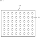
- FIG. 1 is a perspective view of a bladder monitoring apparatus according to an embodiment of the present disclosure.
- a bladder monitoring apparatus 100 may include: an ultrasonic sensor module 120 including an ultrasonic sensor configured to transmit an ultrasonic wave 101 toward a front wall of a bladder and receive the ultrasonic wave 101 returning after being reflected by the front wall of the bladder; a control module 130 configured to measure a passage time interval from a time point at which the ultrasonic sensor transmits the ultrasonic wave 101 to a time point at which the ultrasonic sensor receives the reflected ultrasonic wave 101, calculate distance information from the passage time interval and a speed of the ultrasonic wave 101, and calculate a volume of the bladder from the distance information and configuration information input from the outside; and an output module 140 configured to display the bladder volume calculated by the control module 130.
- the bladder monitoring apparatus 100 may be configured in various types by a person who implements the present disclosure such that the ultrasonic sensor module 120 is oriented toward a bladder, and may be mounted to a user.
- the bladder monitoring apparatus 100 may be implemented to include an adhesive and is thus attachable to the skin, and the bladder monitoring apparatus 100 may be implemented in a type of belt to be fixed while surrounding a user's body.
- the present disclosure is not limited to such an embodiment, and may be variously carried out in the scope as set forth in the claims of the present disclosure.
- the ultrasonic sensor module 120 may include an ultrasonic sensor configured to transmit the ultrasonic wave 101 and receive the ultrasonic wave 101 returning after being reflected by a front wall of a bladder.
- the control module 130 may be configured to calculate a passage time interval indicating a passage time from a time point at which the ultrasonic sensor transmits the ultrasonic wave 101 to a time point at which the ultrasonic sensor receives the reflected ultrasonic wave 101.
- the control module 130 may be configured to calculate distance information from the passage time interval and a speed of the ultrasonic wave 101, and receive configuration information from the outside. Accordingly, the control module 130 may calculate a volume of the bladder and a bladder volume ratio from the distance information and the configuration information. A detailed description thereof will be described with reference to FIG. 3 .
- the output module 140 may be configured to output the bladder volume and the bladder volume ratio.
- the bladder volume may be measured by the bladder monitoring apparatus 100, and the bladder volume ratio may indicate a ratio of the bladder volume to a bladder volume limit described below.
- the output module 140 may be configured to output a notification when the bladder volume ratio is larger than a pre-configured notification output ratio.
- the control module 130 may be configured to receive an input of a notification output ratio.
- the notification such as a sound notification, a light notification, and a vibration notification may be output.
- the output module 140 may be configured to output the bladder volume and the bladder volume ratio in a numerical type.
- the numerical type may express the bladder volume ratio as a percentage related to a bladder volume limit and may express a value of the bladder volume calculated from the bladder volume limit and the bladder volume ratio.
- the output module 140 may be configured to output the bladder volume and the bladder volume ratio in a pictorial type.
- the pictorial type may indicate coloring a picture showing a shape of an empty bladder according to the bladder volume ratio.
- the pictorial type may show a bladder shape expanding according to the bladder volume ratio.
- the output module 140 may be configured to output the bladder volume and the bladder volume ratio in a stepwise type. Stages may be configured according to a predetermined ratio interval in relation to a bladder volume limit, and the output module 140 may be configured to, when the bladder volume ratio is equal to or smaller than a minimum value of a particular stage, output the corresponding stage.
- FIG. 2 is a bottom view of an ultrasonic sensor module according to an embodiment of the present disclosure.
- the ultrasonic sensor module 120 may include multiple ultrasonic sensors 121 arranged according to a two-dimensional arrangement.
- the ultrasonic sensor module 120 may include different numbers of ultrasonic sensors 121 according to a size of a user's bladder. For example, the volume of the bladder of a small person can be measured with a smaller number of ultrasonic sensors 121 compared to that of a large person. Therefore, the ultrasonic sensor module 120 included in the bladder monitoring apparatus 100 for a small person may include a smaller number of ultrasonic sensors 121.
- the ultrasonic sensor module 120 may cause the ultrasonic sensors 121 to transmit the ultrasonic waves 101 according to a pre-configured ultrasonic wave transmission period.
- the control module 130 may receive an input of the ultrasonic wave transmission period.
- the bladder monitoring apparatus 100 may output a bladder volume which is changed according to the ultrasonic wave transmission period.
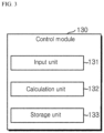
- FIG. 3 is a control block diagram of a control module according to an embodiment of the present disclosure.
- the control module 130 may include: an input unit 131 configured to receive configuration information relating to a bladder volume from the outside; a calculation unit 132 configured to calculate the bladder volume from the configuration information, a passage time interval, and a speed of the ultrasonic wave 101; and a storage unit 133 configured to store information generated from the input unit 131 or the calculation unit 132.
- the input unit 131 may be configured to receive control information and other input information from the outside.
- the configuration information may include a bladder volume limit, a front wall distance limit, and a front wall to rear wall distance limit.
- the configuration information may be information measured by a medical device, and the medical device may be configured to measure a bladder volume while an ultrasonic sensor is in contact with the skin.
- the medical device may be configured to measure a distance to a front wall of a bladder or a rear wall of the bladder through the ultrasonic sensor, and the medical device may be configured to measure a bladder volume limit, a front wall distance limit, and a front wall to rear wall distance limit.
- the configuration information measured by the medical device may include distance information relating to multiple particular points positioned on the front wall of the bladder. Therefore, the configuration information may include a percentage indicating the position of each of the particular points on the entire front wall of the bladder.
- the bladder volume limit may indicate the volume of a user's bladder when a user is required to empty the bladder, and the bladder volume limit may indicate the volume of a bladder at a time point at which the bladder is filled with a designated volume of urine.
- the designated volume may cause the bladder monitoring device 100 to output a notification to alert a user to empty his/her bladder.
- the front wall distance limit may indicate a distance from the ultrasonic sensor 121 to a front wall of a bladder, and may be measured by using the bladder volume limit.
- the front wall distance limit may be measured with respect to multiple particular points positioned on the front wall of the bladder.
- the front wall to rear wall distance limit may indicate a distance from a front wall of a bladder to a rear wall of the bladder, and may be measured by using the bladder volume limit.
- the front wall to rear wall distance limit may be measured with respect to multiple particular points positioned on the front wall of the bladder.
- the other input information may include an output type, a notification type, an operation configuration, etc.
- the output type may include a numerical type, a pictorial type, and a stepwise type
- the notification type may include a sound notification, a light notification, and a vibration notification.
- the operation configuration may include an ultrasonic wave transmission period, an initialization configuration, the number of stages, etc.
- the ultrasonic wave transmission period may indicate a time interval according to which the ultrasonic sensor 121 transmits the ultrasonic wave 101.
- the initialization configuration may be an input to remove all information stored in the bladder monitoring apparatus 100.
- the number of stages may be used for the output module 140 to output a bladder volume and a bladder volume ratio in a stepwise type, and a minimum value of each of the stages may be determined according to the number of stages. For example, if the number of stages is four, a bladder volume and a bladder volume ratio may be output in four stages, and the output module 140 may output each of the stages when the bladder volume ratio is equal to or smaller than 25 %, 50 %, 75 %, or 100 %.
- the input unit 131 may be configured to receive an input a screen brightness, contrast, color, etc. which are configurations related to the output type of the output module 140.
- the input unit 131 may be configured to receive an input of a sound volume, a sound type, a light brightness, a light period, a lighting time, a vibration intensity, a vibration period, a vibration time, etc., which are configurations related to the notification type of the output module 140.
- the calculation unit 132 may be configured to measure a passage time interval from a time point at which each of the ultrasonic sensors 121 transmits the ultrasonic wave 101 to a time point at which the same receives the reflected ultrasonic wave 101.
- the calculation unit 132 may be configured to calculate distance information.
- the distance information may include distance ratio information, a front wall distance 103, a front wall to rear wall distance 104, a bladder volume ratio, a bladder volume, etc.
- the distance ratio information may indicate a ratio between a front wall distance limit and a front wall to rear wall distance limit.
- the front wall distance limit may be in inverse proportion to the front wall to rear wall distance limit.
- the distance ratio information may be calculated with respect to each of particular points positioned on a front wall of a bladder.
- the front wall distance 103 may be calculated from a passage time interval and the speed of the ultrasonic wave 101. Specifically, the front wall distance 103 may be calculated by multiplying the speed of the ultrasonic wave 101 to a value calculated by dividing the passage time interval by two. The front wall distance 103 may be calculated with respect to each of particular points positioned on a front wall of a bladder.
- the front wall to rear wall distance 104 may indicate a distance from a front wall of a bladder to a rear wall of the bladder.
- the front wall to rear wall distance 104 may be calculated from the front wall distance 103 and distance ratio information.
- a ratio between a front wall distance limit and a front wall to rear wall distance limit may be the same as a ratio between the front wall distance 103 and the front wall to rear wall distance 104.
- the front wall to rear wall distance 104 may be calculated from the front wall distance 103 and distance ratio information.
- the front wall distance 103 and the front wall to rear wall distance 104 may be in inverse proportion to each other.
- the front wall to rear wall distance 104 may be calculated with respect to each of particular points positioned on a front wall of a bladder.
- the bladder volume may be calculated from multiple front wall to rear wall distances 104 calculated in the same ultrasonic wave transmission period.
- the multiple front wall to rear wall distances 104 may be calculated by using the multiple ultrasonic sensors 121.
- the bladder volume ratio may indicate a ratio of a bladder volume to a bladder volume limit. Through this ratio, a user can identify a state of his/her bladder, and know when he/she is required to urinate.
- the calculation unit 132 may be configured to calculate position information of multiple particular points on a front wall of a bladder.
- the position information may be a percentage related to a distance from one end of the front wall of the bladder to the other end.
- the calculation unit 132 may be configured to calculate distance information with respect to each of particular points positioned on a front wall of a bladder.
- the distance information may include distance ratio information, the front wall distance 103, the front wall to rear wall distance 104, etc.
- the storage unit 133 may be configured to store configuration information and other inputs.
- the storage unit 133 may be configured to store distance ratio information, the front wall distance 103, the front wall to rear wall distance 104, a bladder volume ratio, a bladder volume, etc.
- the storage unit 133 may be configured to, when the output module 140 outputs a bladder volume or a bladder volume ratio, remove the front wall distance 103 and the front wall to rear wall distance 104 which are stored in the storage unit 133.
- the storage unit 133 may be configured to overwrite the front wall distance 103, the front wall to rear wall distance 104, a bladder volume, and a bladder volume ratio which are newly calculated, on the front wall distance 103, the front wall to rear wall distance 104, a bladder volume, and a bladder volume ratio which are previously calculated, in a process where the output module 140 outputs a bladder volume or a bladder volume ratio, and a new bladder volume or a new bladder volume ratio is calculated according to an ultrasonic wave transmission period.
- the storage unit 133 may be configured to, when an initialization input is received by the input unit 131, remove all information stored in the storage unit 133. Accordingly, the input unit 131 may receive an input of configuration information again to reuse the bladder monitoring apparatus 100.
- the bladder monitoring apparatus 100 may calculate a bladder volume from the number of ultrasonic sensors 121 measuring a front wall of a bladder, and a passage time interval from a time point at which the ultrasonic sensors 121 transmit the ultrasonic waves 101 toward a front wall of a bladder to a time point at which the same receive the reflected ultrasonic waves 101.
- the bladder monitoring apparatus 100 can simply and easily measure a bladder volume by calculating, in various methods, the number of ultrasonic sensors 121 measuring a front wall of a bladder, and a passage time interval from transmission of the ultrasonic wave 101 to reception of the reflected ultrasonic wave 101.
- a specific embodiment for simply and easily measuring a bladder volume will be described.
- the calculation unit 132 may generate a passage time interval from a time point at which each of the ultrasonic sensors 121 transmits the ultrasonic wave 101 toward a front wall of a bladder to a time point at which the same receives the ultrasonic wave 101 returning after being reflected by the front wall of the bladder.
- the calculation unit 132 may generate the number of reception sensors, which indicates the number of ultrasonic sensors each of which has measured a passage time interval falling within a range allowing the determination of reception of the ultrasonic wave 101 returning after being reflected by the front wall of the bladder.
- the calculation unit 132 may calculate a front wall distance indicating a distance from the ultrasonic sensor to the front wall of the bladder, from the passage time interval and the speed of the ultrasonic wave 101.
- the input unit 131 may receive a bladder limit measurement command from the outside.
- the ultrasonic sensor module 120 may transmit, when the input unit 131 receives an input of a bladder limit measurement command, the ultrasonic wave 101 toward the front wall of the bladder and receive the reflected ultrasonic wave 101. Accordingly, the calculation unit 132 may generate the passage time interval and the number of reception sensors.
- the calculation unit 132 may calculate a front wall distance limit indicating a distance from the ultrasonic sensor to the front wall of the bladder from the speed of the ultrasonic wave 101 and the passage time interval generated by the bladder limit measurement command received by the input unit 131.
- the calculation unit 132 may designate, as a limit number of reception sensors, the number of reception sensors generated by the bladder limit measurement command received by the input unit 131.
- the storage unit 133 may store the front wall distance limit and the limit number of reception sensors which are generated by the calculation unit 132.
- the calculation unit 132 may generate a unit bladder volume by dividing, by the limit number of reception sensors, a bladder capacity causing an output of a notification to alert a user to urinate.
- the bladder capacity causing an output of a notification may be 400 millimeters.
- the calculation unit 132 may multiply the number of reception sensors to the unit bladder volume to simply and easily calculate the bladder volume.
- the output module 140 may output a notification when the simply and easily calculated bladder volume is equal to or larger than the bladder capacity causing an output of a notification.
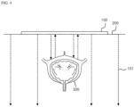
- FIG. 4 is a schematic diagram of a method of transmitting an ultrasonic wave to a bladder and receiving the reflected ultrasonic wave according to an embodiment of the present disclosure.
- the bladder monitoring apparatus 100 may be implemented to be detachably attached to a user's skin 200. Accordingly, the user may attach the bladder monitoring apparatus 100 to the user's skin 200 adjacent to a bladder 300, and start a bladder volume measurement.
- the bladder monitoring apparatus 100 may transmit the ultrasonic wave 101 toward the bladder 300.
- the bladder monitoring apparatus 100 may transmit the ultrasonic wave 101 toward a front wall of the bladder, and receive the ultrasonic wave 101 returning after being reflected by the front wall of the bladder. Through this process, the bladder monitoring apparatus may measure a passage time interval from a time point of transmission of the ultrasonic wave 101 to a time point of reception of the ultrasonic wave 101 returning after being reflected by the front wall of the bladder.
- the bladder monitoring apparatus 100 may generate a non-reception signal if reception of the ultrasonic wave 101 returning after being reflected by the front wall of the bladder fails. Accordingly, the bladder monitoring apparatus 100 may measure a range of the front wall of the bladder.
- the bladder monitoring apparatus 100 may transmit the ultrasonic wave 101 according to an ultrasonic wave transmission period, and the bladder monitoring apparatus 100 may re-measure a bladder volume according to the ultrasonic wave transmission period.
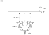
- FIG. 5 is a schematic diagram of a method of measuring distance information in a bladder monitoring method according to an embodiment of the present disclosure.
- a bladder volume may be calculated by detecting only a distance to a front wall of a bladder.
- distance ratio information may be calculated from a front wall distance limit and a front wall to rear wall distance limit which are previously input, and the front wall to rear wall distance 104 may be calculated from the distance ratio information and a front wall distance 103, based on that the distance ratio information can be the same as a ratio between the front wall distance 103 and the front wall to rear wall distance 104.
- the bladder volume may be calculated from multiple front wall to rear wall distances 104 calculated in the same ultrasonic wave transmission period.
- a bladder volume ratio may be calculated by calculating a ratio of the bladder volume to a bladder volume limit.
- FIG. 6 is a schematic diagram illustrating a particular point on a front wall of a bladder according to an embodiment of the present disclosure.
- FIG. 6 An embodiment according to FIG. 6 is provided to help understanding of particular points 310, and the present disclosure is not limited by the embodiment according to FIG. 6 .
- the positions of the particular points 310 may be determined by a percentage related to a range of a bladder front wall, which is measured by the ultrasonic sensors 121.
- a first particular point 311 may be determined to be a position represented by 0 % calculated through calculation of the range of the bladder front wall in percentages.
- a second particular point 312 may be determined to be a position represented by 16.67 % calculated through calculation of the range of the bladder front wall in percentages.
- a third particular point 313 may be determined to be a position represented by 33.34 % calculated through calculation of the range of the bladder front wall in percentages.
- a fourth particular point 314 may be determined to be a position represented by 50 % calculated through calculation of the range of the bladder front wall in percentages.
- a fifth particular point 311 may be determined to be a position represented by 66.67 % calculated through calculation of the range of the bladder front wall in percentages.
- a sixth particular point 316 may be determined to be a position represented by 83.34 % calculated through calculation of the range of the bladder front wall in percentages.
- a seventh particular point 317 may be determined to be a position represented by 100 % calculated through calculation of the range of the bladder front wall in percentages.
- a front wall distance limit may be a distance from the ultrasonic sensor 121 to each of the particular points 310 positioned on the bladder front wall.
- a front wall to rear wall distance limit may be a distance to a bladder rear wall from each of the particular points 310 positioned on the bladder front wall.
- the bladder rear wall may include a point at which the bladder rear wall meets a linear line including a particular point 310 and further including a front wall distance limit 103 measured with respect to the corresponding particular point 310.
- a front wall distance 103 may be a distance from the ultrasonic sensor 121 to each of the particular points 310 positioned on the bladder front wall.
- a front wall to rear wall distance 104 may be a distance to the bladder rear wall from each of the particular points 310 positioned on the bladder front wall.
- the bladder rear wall may include a point at which the bladder rear wall meets a linear line including a particular point 310 and further including a front wall distance 103 measured with respect to the corresponding particular point 310.
- FIG. 7 is a flowchart of a bladder monitoring method according to an embodiment of the present disclosure.
- a bladder monitoring method may include: an ultrasonic wave transmission operation 710 of transmitting, by the ultrasonic sensor 121, the ultrasonic wave 101 toward a front wall of a bladder; an ultrasonic wave reception operation 720 of receiving the ultrasonic wave 101 returning after reflection, by the front wall of the bladder, of the ultrasonic wave 101 transmitted toward the front wall of the bladder in the ultrasonic wave transmission operation 710, and generating a passage time interval relating to the ultrasonic wave 101; an apparatus control operation 730 of calculating a volume of the bladder from the passage time interval and a speed of the ultrasonic wave 101; and a volume output operation 740 of outputting the bladder volume calculated in the apparatus control operation 730.
- An apparatus attachment operation 700 may be an operation of attaching the bladder monitoring apparatus 100 on a portion at which the ultrasonic wave 101 reaches the bladder 300 when the ultrasonic sensor 121 transmits the ultrasonic wave 101.
- the ultrasonic wave transmission operation 710 may be an operation of transmitting, by the ultrasonic sensor 121, the ultrasonic wave 101 toward a front wall of a bladder.
- the ultrasonic wave 101 may be transmitted according to an ultrasonic wave transmission period input by a user. Accordingly, the ultrasonic wave transmission operation 710, the ultrasonic wave reception operation 720, the apparatus control operation 730, and the volume output operation 740 may be repeated according to the ultrasonic wave transmission period.
- the passage time interval may indicate a time interval from transmission of the ultrasonic wave 101 to reception of the reflected ultrasonic wave 101.
- the ultrasonic wave reception operation 720 may be an operation of receiving the ultrasonic wave 101 which returns after reflection of the ultrasonic wave 101 colliding with the bladder 300.
- the measurement of the passage time interval which has started in the ultrasonic wave transmission operation 710 may be terminated.
- a front wall distance 103 may be calculated from the passage time interval.
- a bladder volume ratio and a bladder volume may be calculated from configuration information input from the outside and the front wall distance 103.
- the apparatus control operation 730 will be described in detail with reference to FIG. 7 .
- the bladder volume and the bladder volume ratio may be output.
- the bladder volume may be calculated in the apparatus control operation 730, and the bladder volume ratio may represent a ratio of the bladder volume to a bladder volume limit.
- a notification when the bladder volume ratio is higher than a pre-configured notification output ratio, a notification may be output.
- a notification may be output in the apparatus control operation 730.
- an input of a notification output ratio may be received in the apparatus control operation 730.
- the notification such as a sound notification, a light notification, and a vibration notification may be output.
- the bladder volume and the bladder volume ratio may be output in a numerical type.
- the numerical type may express the bladder volume ratio as a percentage related to the bladder volume limit and may express a value of a bladder volume calculated from the bladder volume limit and the bladder volume ratio.
- the bladder volume and the bladder volume ratio may be output in a pictorial type.
- the pictorial type may indicate coloring a picture showing the empty bladder 300 according to the bladder volume ratio.
- the pictorial type may show a pictorial shape of the bladder 300 expanding according to the bladder volume ratio.
- the bladder volume and the bladder volume ratio may be output in a stepwise type. Stages may be configured according to a predetermined ratio interval in relation to a bladder volume limit, and in the volume output operation 740, when the bladder volume ratio is equal to or smaller than a minimum value of a particular stage, the corresponding stage may be output.
- FIG. 8 is a flowchart of an apparatus control operation in a bladder monitoring method according to an embodiment of the present disclosure.
- the apparatus control operation 730 may include: a configuration input operation 731 of receiving configuration information from the outside; a reference calculation operation 732 of calculating distance ratio information from the configuration information; a volume calculation operation 733 of calculating the bladder volume from the configuration information, the distance ratio information, and the passage time interval; and an information storage operation 734 of storing the pieces of information which are generated in the configuration input operation 731, the reference calculation operation 732, and the volume calculation operation 733; and an information removal operation 735 of removing information stored in the information storage operation 734.
- configuration information and other input information may be received from the outside.
- the configuration input operation 731 may be started before the apparatus attachment operation 700. In this case, a passage time interval for calculating a bladder volume has not been measured yet, and thus the procedure may be performed up to the reference calculation operation 732.
- the configuration information may include a bladder volume limit, a front wall distance limit, and a front wall to rear wall distance limit, and the other input information may include an output type, a notification type, an operation configuration, etc.
- the configuration information may be information measured by a medical device, and the medical device may be configured to measure a bladder volume while an ultrasonic sensor is in contact with the skin 200.
- the medical device may be configured to measure a distance to a front wall of a bladder or a rear wall of the bladder through the ultrasonic sensor, and the medical device may be configured to measure a bladder volume limit, a front wall distance limit, and a front wall to rear wall distance limit.
- the configuration information measured by the medical device may include distance information relating to the multiple particular points 310 positioned on the front wall of the bladder. Therefore, the configuration information may include a percentage indicating the position of each of the particular points 310 with respect to a range of the front wall of the bladder.
- the bladder volume limit may indicate the volume of a user's bladder when a user is required to empty the bladder, and the bladder volume limit may indicate the volume of the bladder 300 at a time point at which the bladder 300 is filled with a designated volume of urine.
- the designated volume may cause the bladder monitoring device 100 to output a notification to alert the user to empty the bladder 300.
- the front wall distance limit may indicate a distance from the ultrasonic sensor 121 to a front wall of a bladder, and may be measured by using the bladder volume limit.
- the front wall distance limit may be measured with respect to the multiple particular points 310 positioned on the front wall of the bladder.
- the front wall to rear wall distance limit may indicate a distance from a front wall of a bladder to a rear wall of the bladder, and may be measured by using the bladder volume limit.
- the front wall to rear wall distance limit may be measured with respect to the multiple particular points 310 positioned on the front wall of the bladder.
- the other input information may include an output type, a notification type, an operation configuration, etc.
- the output type may include a numerical type, a pictorial type, and a stepwise type
- the notification type may include a sound notification, a light notification, and a vibration notification.
- the operation configuration may include an ultrasonic wave transmission period, an initialization configuration, the number of stages, etc.
- the ultrasonic wave transmission period may indicate a time interval according to which the ultrasonic sensor 121 transmits the ultrasonic wave 101.
- the initialization configuration may be an input to remove all information stored in the information storage operation 734.
- the number of stages may be used when a bladder volume and a bladder volume ratio are output in a stepwise type in the volume output operation 740, and a minimum value of each of the stages may be determined according to the number of stages. For example, if the number of stages is four, a bladder volume and a bladder volume ratio may be output in four stages, and in the volume output operation 740, when the bladder volume ratio is equal to or smaller than 25 %, 50 %, 75 %, or 100 %, each of the stages may be output.
- distance ratio information may be calculated.
- the distance ratio information may indicate that the front wall distance limit and the front wall to rear wall distance limit are be in inverse proportion to each other.
- the front wall distance 103 may be calculated from the passage time interval and the speed of the ultrasonic wave 101.
- the front wall to rear wall distance 104 may be calculated from the front wall distance 103 and the distance ratio information. Specifically, a ratio between the front wall distance limit and the front wall to rear wall distance limit may be the same as a ratio between the front wall distance 103 and the front wall to rear wall distance 104. Through this information, the front wall to rear wall distance 104 may be calculated from the front wall distance 103 and the distance ratio information.
- a bladder volume and a bladder volume ratio may be calculated.
- the bladder volume may be calculated from multiple front wall to rear wall distances 104 calculated in the same ultrasonic wave transmission period.
- the multiple front wall to rear wall distances 104 may be calculated by using multiple ultrasonic sensors 121.
- the volume calculation operation 733 may be started without the configuration input operation 731 and the reference calculation operation 732 when the ultrasonic wave transmission operation 710 is repeated according to an ultrasonic wave transmission period. Accordingly, the volume calculation operation 733, the information storage operation 734, and the information removal operation 735 may be repeated in order to calculate a new bladder volume ratio and a new bladder volume according to the ultrasonic wave transmission period.
- the generated information may include configuration information, other inputs, distance ratio information, a front wall distance 103, a front wall to rear wall distance 104, a bladder volume ratio, a bladder volume, etc.
- the front wall distance 103 and the front wall to rear wall distance 104 may be removed.
- the front wall distance 103, the front wall to rear wall distance 104, a bladder volume ratio, and a bladder volume may be overwritten on the front wall distance 103, the front wall to rear wall distance 104, a bladder volume ratio, and a bladder volume which are previously calculated, in a process where a new bladder volume ratio or a new bladder volume is calculated through the repetition of the ultrasonic wave transmission operation 710 according to an ultrasonic wave transmission period.
- the bladder volume may be calculated from the number of ultrasonic sensors 121 measuring a front wall of a bladder, and a passage time interval from a time point at which the ultrasonic sensors 121 transmit the ultrasonic waves 101 toward a front wall of a bladder to a time point at which the sensors receive the reflected ultrasonic waves 101.
- the bladder monitoring apparatus 100 can simply and easily measure a bladder volume by calculating, in various methods, the number of ultrasonic sensors 121 measuring a front wall of a bladder, and a passage time interval from transmission of the ultrasonic wave 101 to reception of the reflected ultrasonic wave 101.
- a specific embodiment for simply and easily measuring a bladder volume will be described.
- the passage time interval may indicate a time interval from transmission of the ultrasonic wave 101 to reception of the reflected ultrasonic wave 101.
- the measurement of the passage time interval may be terminated to generate a passage time interval from a time point at which each of the ultrasonic sensors 121 transmits the ultrasonic wave 101 toward a front wall of a bladder to a time point at which the same receives the ultrasonic wave 101 returning after being reflected by the front wall of the bladder.
- the number of reception sensors which indicates the number of ultrasonic sensors each of which has measured a passage time interval falling within a range allowing the determination of reception of the ultrasonic wave 101 returning after being reflected by the front wall of the bladder, may be generated.
- a front wall distance indicating a distance from the ultrasonic sensor to the front wall of the bladder may be calculated from the passage time interval and the speed of the ultrasonic wave 101.
- a bladder limit measurement command may be received from the outside.
- the ultrasonic sensor module 120 may transmit, when an input of a bladder limit measurement command is received in the configuration input operation 731, the ultrasonic wave 101 toward the front wall of the bladder and receive the reflected ultrasonic wave 101. Accordingly, in the ultrasonic wave reception operation 720, the passage time interval and the number of reception sensors may be generated.
- a front wall distance limit indicating a distance from the ultrasonic sensor to the front wall of the bladder may be calculated from the speed of the ultrasonic wave 101 and the passage time interval generated by the bladder limit measurement command received in the configuration input operation 731.
- the number of reception sensors generated by the bladder limit measurement command received in the configuration input operation 731 may be designated as a limit number of reception sensors.
- the front wall distance limit and the limit number of reception sensors which are generated in the apparatus control operation 730 may be stored.
- a unit bladder volume may be generated by dividing, by the limit number of reception sensors, a bladder capacity causing an output of a notification to alert a user to urinate.
- the bladder capacity causing an output of a notification may be 400 millimeters.
- the bladder volume may be simply and easily calculated by multiplying the number of reception sensors to the unit bladder volume.
- a notification may be output when the simply and easily calculated bladder volume is equal to or larger than the bladder capacity causing an output of a notification.
Landscapes
- Health & Medical Sciences (AREA)
- Life Sciences & Earth Sciences (AREA)
- Engineering & Computer Science (AREA)
- Molecular Biology (AREA)
- Animal Behavior & Ethology (AREA)
- Biophysics (AREA)
- Nuclear Medicine, Radiotherapy & Molecular Imaging (AREA)
- Pathology (AREA)
- Radiology & Medical Imaging (AREA)
- Biomedical Technology (AREA)
- Heart & Thoracic Surgery (AREA)
- Medical Informatics (AREA)
- Veterinary Medicine (AREA)
- Surgery (AREA)
- Physics & Mathematics (AREA)
- General Health & Medical Sciences (AREA)
- Public Health (AREA)
- Computer Vision & Pattern Recognition (AREA)
- Gynecology & Obstetrics (AREA)
- Physiology (AREA)
- Ultra Sonic Daignosis Equipment (AREA)
- Measurement Of Levels Of Liquids Or Fluent Solid Materials (AREA)
- Length Measuring Devices Characterised By Use Of Acoustic Means (AREA)
- Supply Devices, Intensifiers, Converters, And Telemotors (AREA)
Claims (13)
- Eine Blasenüberwachungsvorrichtung, die Folgendes beinhaltet:ein Ultraschallsensormodul (120), das einen Ultraschallsensor (121) umfasst, der konfiguriert ist, um eine Ultraschallwelle in Richtung einer Vorderwand einer Blase zu übertragen und die Ultraschallwelle zu empfangen, die zurückkehrt, nachdem sie von der Vorderwand der Blase reflektiert wird;ein Steuerungsmodul (130), das konfiguriert ist, um ein Zeitverlaufsintervall von einem Zeitpunkt, zu dem der Ultraschallsensor (121) die Ultraschallwelle überträgt, bis zu einem Zeitpunkt, zu dem der Ultraschallsensor (121) die Ultraschallwelle empfängt, die zurückkehrt, nachdem sie von der Vorderwand der Blase reflektiert wird, zu messen, Abstandsinformationen aus dem Zeitverlaufsintervall und einer Geschwindigkeit der Ultraschallwelle zu berechnen und ein Volumen der Blase aus den Abstandsinformationen und Konfigurationsinformationseingaben von einer Außenseite zu berechnen;wobei die Konfigurationsinformationen Folgendes beinhalten:ein Blasenvolumenlimit, das das Blasenvolumen eines Zeitpunkts anzeigt, zu dem die Blase mit einem designierten Volumen von Urin gefüllt ist;ein Vorderwandabstandslimit, das einen Abstand von dem Ultraschallsensor (121) zu der Vorderwand der Blase in einem Zustand des Blasenvolumenlimits anzeigt; undein Vorderwand-zu-Rückwand-Abstandslimit, das einen Abstand von der Vorderwand der Blase zu einer Rückwand der Blase in einem Zustand des Blasenvolumenlimits anzeigt; undein Ausgabemodul (140), das konfiguriert ist, um das Blasenvolumen auszugeben, das von dem Steuerungsmodul (130) berechnet wird.
- Vorrichtung gemäß Anspruch 1, wobei das Ultraschallsensormodul (120) mehrere Ultraschallsensoren (121) beinhaltet und die mehreren Ultraschallsensoren (121) gemäß einer zweidimensionalen Anordnung angeordnet sind und konfiguriert sind, um Ultraschallwellen gemäß einer vorkonfigurierten Zeitdauer zu übertragen.
- Vorrichtung gemäß Anspruch 1, wobei das Steuerungsmodul (130) Folgendes beinhaltet:eine Eingabeeinheit (131), die konfiguriert ist, um Konfigurationsinformationen, die sich auf das Blasenvolumen beziehen, von der Außenseite zu empfangen;eine Berechnungseinheit (132), die konfiguriert ist, um das Blasenvolumen aus den Konfigurationsinformationen und dem Zeitverlaufsintervall zu berechnen; undeine Speichereinheit, die konfiguriert ist, um Informationen zu speichern, die von der Eingabeeinheit (131) oder der Berechnungseinheit (132) erzeugt werden.
- Vorrichtung gemäß Anspruch 1, wobei die Abstandsinformationen Folgendes beinhalten:einen Vorderwandabstand, der ein Abstand von dem Ultraschallsensor (121) zu der Vorderwand der Blase ist; undeinen Vorderwand-zu-Rückwand-Abstand, der ein Abstand von der Vorderwand der Blase zu der Rückwand der Blase ist, unddie Berechnungseinheit (132) für Folgendes konfiguriert ist:Berechnen von Abstandsverhältnisinformationen aus dem Vorderwandabstandslimit und dem Vorderwand-zu-Rückwand-Abstandslimit;Berechnen des Vorderwandabstands aus dem Zeitverlaufsintervall und der Geschwindigkeit der Ultraschallwelle;Berechnen des Vorderwand-zu-Rückwand-Abstands aus den Abstandsverhältnisinformationen und dem Vorderwandabstand;Berechnen des Blasenvolumens aus mehreren Vorderwand-zu-Rückwand-Abständen, die in einem Prozess einer Blasenvolumenmessung berechnet werden, der gemäß Übertragung einer Ultraschallwelle durch jeden mehrerer Ultraschallsensoren (121) gestartet wird; undBerechnen eines Blasenvolumenverhältnisses aus dem Blasenvolumenlimit und dem Blasenvolumen.
- Vorrichtung gemäß Anspruch 4, wobei die Speichereinheit (133) für Folgendes konfiguriert ist:Speichern von mindestens einem der Abstandsverhältnisinformationen, des Vorderwandabstands, des Vorderwand-zu-Rückwand-Abstands, des Blasenvolumenverhältnisses und des Blasenvolumens, die von der Berechnungseinheit (132) berechnet werden; undSpeichern der Konfigurationsinformationen, die von der Eingabeeinheit (131) empfangen werden.
- Vorrichtung gemäß Anspruch 5, wobei das Ausgabemodul (140) für Folgendes konfiguriert ist:Ausgeben mindestens eines des Blasenvolumens oder des Blasenvolumenverhältnisses, das in der Speichereinheit (133) gespeichert wird; undAusgeben einer Benachrichtigung, wenn das Blasenvolumenverhältnis größer als ein vorkonfiguriertes Benachrichtigungsausgabeverhältnis ist.
- Vorrichtung gemäß Anspruch 6, wobei die Speichereinheit (133) konfiguriert ist, um den Vorderwandabstand und den Vorderwand-zu-Rückwand-Abstand, die in der Speichereinheit (133) gespeichert sind, zu entfernen, wenn das Ausgabemodul (140) mindestens eines von dem Blasenvolumen oder dem Blasenvolumenverhältnis ausgibt.
- Ein Blasenüberwachungsverfahren, das Folgendes beinhaltet:eine Ultraschallwellenübertragungsoperation zum Übertragen, durch einen Ultraschallsensor (121), einer Ultraschallwelle in Richtung einer Vorderwand einer Blase;eine Ultraschallwellenempfangsoperation zum Empfangen der Ultraschallwelle, die nach der Reflexion, durch die Vorderwand der Blase, der Ultraschallwelle, die in der Ultraschallwellenübertragungsoperation in Richtung der Vorderwand der Blase übertragen wird, zurückkehrt, und zum Erzeugen eines Zeitverlaufsintervalls, das sich auf die Ultraschallwelle bezieht;eine Vorrichtungssteuerungsoperation zum Berechnen von Abstandsinformationen aus dem Zeitverlaufsintervall und einer Geschwindigkeit der Ultraschallwelle und zum Berechnen eines Volumens der Blase aus den Abstandsinformationen und Konfigurationsinformationseingabe von einer Außenseite;wobei die Konfigurationsinformationen Folgendes beinhalten:ein Blasenvolumenlimit, das das Blasenvolumen eines Zeitpunkts anzeigt, zu dem die Blase mit einem designierten Volumen von Urin gefüllt ist;ein Vorderwandabstandslimit, das einen Abstand von dem Ultraschallsensor (121) zu der Vorderwand der Blase in einem Zustand des Blasenvolumenlimits anzeigt; undein Vorderwand-zu-Rückwand-Abstandslimit, das einen Abstand von der Vorderwand der Blase zu einer Rückwand der Blase in einem Zustand des Blasenvolumenlimits anzeigt; undeine Volumenausgabeoperation zum Ausgeben des Blasenvolumens, das in der Vorrichtungssteuerungsoperation berechnet wird.
- Verfahren gemäß Anspruch 8, wobei die Vorrichtungssteuerungsoperation Folgendes beinhaltet:eine Konfigurationseingabeoperation zum Empfangen der Konfigurationsinformationen von der Außenseite;eine Referenzberechnungsoperation zum Berechnen von Abstandsverhältnisinformationen aus den Konfigurationsinformationen;eine Volumenberechnungsoperation zum Berechnen des Blasenvolumens aus den Abstandsinformationen und den Abstandsverhältnisinformationen; undeine Informationsspeicherungsoperation zum Speichern von mindestens einem von Informationselementen, die in der Konfigurationseingabeoperation, der Referenzberechnungsoperation und der Volumenberechnungsoperation erzeugt werden; undeine Informationsentfernungsoperation zum Entfernen des mindestens einen Informationselements, das in der Informationsspeicherungsoperation gespeichert wird.
- Verfahren gemäß Anspruch 8, wobei die Abstandsinformationen Folgendes beinhalten:einen Vorderwandabstand, der ein Abstand von dem Ultraschallsensor (121) zu der Vorderwand der Blase ist; undeinen Vorderwand-zu-Rückwand-Abstand, der ein Abstand von der Vorderwand der Blase zu der Rückwand der Blase ist, unddie Volumenberechnungsoperation Folgendes beinhaltet:Berechnen des Vorderwandabstands aus dem Zeitverlaufsintervall und der Geschwindigkeit der Ultraschallwelle;Berechnen des Vorderwand-zu-Rückwand-Abstands aus den Abstandsverhältnisinformationen und dem Vorderwandabstand;Berechnen des Blasenvolumens aus mehreren Vorderwand-zu-Rückwand-Abständen, die in einem Prozess einer Blasenvolumenmessung berechnet werden, der gemäß Übertragung einer Ultraschallwelle durch jeden mehrerer Ultraschallsensoren (121) gestartet wird; undBerechnen eines Blasenvolumenverhältnisses aus dem Blasenvolumenlimit und dem Blasenvolumen.
- Verfahren gemäß Anspruch 10, wobei die Informationsspeicherungsoperation das Speichern mindestens eines der Konfigurationsinformationen, der Abstandsverhältnisinformationen, des Vorderwandabstands, des Vorderwand-zu-Rückwand-Abstands, des Blasenvolumenverhältnisses und des Blasenvolumens beinhaltet.
- Verfahren gemäß Anspruch 11, wobei die Volumenausgabeoperation Folgendes beinhaltet:Ausgeben mindestens eines des Blasenvolumens oder des Blasenvolumenverhältnisses, das in der Informationsspeicherungsoperation gespeichert wird; undAusgeben einer Benachrichtigung, wenn das Blasenvolumenverhältnis größer als ein vorkonfiguriertes Benachrichtigungsausgabeverhältnis ist.
- Verfahren gemäß Anspruch 12, wobei, wenn mindestens eines des Blasenvolumens oder des Blasenvolumenverhältnisses in der Volumenausgabeoperation ausgegeben wird, die Informationsentfernungsoperation das Entfernen des Vorderwandabstands und des Vorderwand-zu-Rückwand-Abstands beinhaltet, die in der Informationsspeicherungsoperation gespeichert werden.
Applications Claiming Priority (2)
| Application Number | Priority Date | Filing Date | Title |
|---|---|---|---|
| KR1020190059309A KR102181137B1 (ko) | 2019-05-21 | 2019-05-21 | 초음파 센서를 이용한 방광 모니터링 장치 및 방법 |
| PCT/KR2020/005002 WO2020235810A2 (ko) | 2019-05-21 | 2020-04-14 | 초음파 센서를 이용한 방광 모니터링 장치 및 방법 |
Publications (4)
| Publication Number | Publication Date |
|---|---|
| EP3973886A2 EP3973886A2 (de) | 2022-03-30 |
| EP3973886A4 EP3973886A4 (de) | 2023-06-21 |
| EP3973886B1 true EP3973886B1 (de) | 2025-06-04 |
| EP3973886C0 EP3973886C0 (de) | 2025-06-04 |
Family
ID=73458537
Family Applications (1)
| Application Number | Title | Priority Date | Filing Date |
|---|---|---|---|
| EP20809992.9A Active EP3973886B1 (de) | 2019-05-21 | 2020-04-14 | Blasenüberwachungsvorrichtung und verfahren unter verwendung eines ultraschallsensors |
Country Status (4)
| Country | Link |
|---|---|
| US (1) | US12471884B2 (de) |
| EP (1) | EP3973886B1 (de) |
| KR (1) | KR102181137B1 (de) |
| WO (1) | WO2020235810A2 (de) |
Families Citing this family (6)
| Publication number | Priority date | Publication date | Assignee | Title |
|---|---|---|---|---|
| KR102460829B1 (ko) * | 2020-11-03 | 2022-10-28 | 재단법인대구경북과학기술원 | 방광 모니터링 장치 및 방광 모니터링 장치의 제어 방법 |
| KR102428397B1 (ko) | 2021-02-19 | 2022-08-02 | 재단법인 대구경북첨단의료산업진흥재단 | 운동성 장기 모사 ex vivo 시스템 |
| KR102528242B1 (ko) * | 2022-03-18 | 2023-05-03 | (주) 엠큐브테크놀로지 | 인공지능을 이용하여 방광용적을 측정하는 의료영상장치 및 의료영상장치의 동작 방법 |
| KR20250041329A (ko) * | 2023-09-18 | 2025-03-25 | (주) 엠큐브테크놀로지 | 방광 부피 측정 시스템 및 상기 시스템에서의 방광 부피 측정 방법 |
| WO2025143266A1 (ja) * | 2023-12-28 | 2025-07-03 | DFree株式会社 | 尿量推定システム、尿量推定方法及び尿量推定プログラム |
| KR20250128490A (ko) | 2024-02-21 | 2025-08-28 | 충북보건과학대학교 산학협력단 | 배뇨 시기 알림 장치 |
Family Cites Families (15)
| Publication number | Priority date | Publication date | Assignee | Title |
|---|---|---|---|---|
| US5964710A (en) * | 1998-03-13 | 1999-10-12 | Srs Medical, Inc. | System for estimating bladder volume |
| US6213949B1 (en) * | 1999-05-10 | 2001-04-10 | Srs Medical Systems, Inc. | System for estimating bladder volume |
| IL124703A0 (en) | 1998-06-01 | 1999-01-26 | Abramovitch Aron | Method and device for measurement of urine bladder functions and urination |
| KR100307085B1 (ko) | 1998-12-12 | 2001-11-30 | 최흥호 | 초음파요실금경보시스템및방법 |
| IL158379A0 (en) * | 2003-10-13 | 2004-05-12 | Volurine Israel Ltd | Non invasive bladder distension monitoring apparatus to prevent enuresis, and method of operation therefor |
| DK1731101T3 (da) * | 2004-03-31 | 2009-09-07 | Nat Inst Of Advanced Ind Scien | Ultralydsensor til bestemmelse af urinvolumen |
| KR100779548B1 (ko) | 2006-04-25 | 2007-11-27 | (주) 엠큐브테크놀로지 | 방광 진단용 초음파 진단 장치 및 초음파 진단 방법 |
| US20110137172A1 (en) * | 2006-04-25 | 2011-06-09 | Mcube Technology Co., Ltd. | Apparatus and method for measuring an amount of urine in a bladder |
| KR101071994B1 (ko) | 2009-04-22 | 2011-10-12 | 대전보건대학 산학협력단 | 방광용적 측정장치 |
| JP2011183142A (ja) * | 2010-02-09 | 2011-09-22 | Nagasaki Univ | 非侵襲尿量推定センサユニット、非侵襲尿量推定装置及び排尿管理システム |
| JP2013523305A (ja) * | 2010-04-08 | 2013-06-17 | コーニンクレッカ フィリップス エレクトロニクス エヌ ヴィ | 排尿予測 |
| KR101579740B1 (ko) * | 2014-09-01 | 2015-12-23 | 삼성메디슨 주식회사 | 초음파 진단장치, 그에 따른 초음파 진단 방법 및 그에 따른 컴퓨터 판독 가능한 저장매체 |
| EP3308713B1 (de) * | 2015-06-12 | 2020-05-06 | Triple W Japan K.K. | Vorrichtung zur kalkulation einer urinmenge und verfahren zur kalkulation einer urinmenge |
| WO2018148332A1 (en) * | 2017-02-07 | 2018-08-16 | Ultrasense Medical, Inc. | Wearable ultrasound device |
| KR101930883B1 (ko) * | 2018-04-19 | 2018-12-19 | 주식회사 메디벨바이오 | 방광 내 잔뇨량 모니터링을 위한 웨어러블 초음파 측정장치 및 측정방법 |
-
2019
- 2019-05-21 KR KR1020190059309A patent/KR102181137B1/ko active Active
-
2020
- 2020-04-14 EP EP20809992.9A patent/EP3973886B1/de active Active
- 2020-04-14 US US17/603,079 patent/US12471884B2/en active Active
- 2020-04-14 WO PCT/KR2020/005002 patent/WO2020235810A2/ko not_active Ceased
Also Published As
| Publication number | Publication date |
|---|---|
| US12471884B2 (en) | 2025-11-18 |
| WO2020235810A3 (ko) | 2021-01-07 |
| WO2020235810A2 (ko) | 2020-11-26 |
| EP3973886A4 (de) | 2023-06-21 |
| EP3973886C0 (de) | 2025-06-04 |
| EP3973886A2 (de) | 2022-03-30 |
| US20220183660A1 (en) | 2022-06-16 |
| KR102181137B1 (ko) | 2020-11-20 |
Similar Documents
| Publication | Publication Date | Title |
|---|---|---|
| EP3973886B1 (de) | Blasenüberwachungsvorrichtung und verfahren unter verwendung eines ultraschallsensors | |
| EP2989989B1 (de) | Ultraschallinstrument zur messung des harnvolumens | |
| EP3570737B1 (de) | Nichtinvasive blutdruckmessung mittels pulswellengeschwindigkeit | |
| EP3243439B1 (de) | Vorrichtung und verfahren zur bestimmung der fetalen herzfrequenz | |
| CN105682551B (zh) | 用于监测对象的膀胱体积的设备和方法 | |
| CN109069121A (zh) | 用于ctg超声换能器的定位支持和胎儿心率配准支持 | |
| EP0339057A1 (de) | Akustisches entferungsmessgerät | |
| CN106859626B (zh) | 一种胎心检测设备 | |
| EP1806099A4 (de) | Ultraschallgerät und ultraschallgerät-kontrollverfahren | |
| JP5890931B1 (ja) | 超音波尿量測定器及び超音波尿量測定器を用いた尿量管理データ作成表示方法 | |
| JP2015154884A (ja) | 超音波測定装置及び超音波測定方法 | |
| JP5553315B2 (ja) | ドプラセンサー | |
| EP4338681A1 (de) | Überwachungseinrichtung | |
| JP2000308639A (ja) | 脈波検出装置 | |
| JP3388522B2 (ja) | 血圧測定システムおよび血圧値演算装置 | |
| Beauchamp-Parent et al. | New reconfigurable ultrasonic enuresis monitoring system | |
| WO2016030959A1 (ja) | 超音波尿量測定器及びその超音波プローブの位置決め方法 | |
| WO2025143265A1 (ja) | 超音波測定システム、ユーザ端末、超音波測定方法及び超音波測定プログラム | |
| JPH07327994A (ja) | 超音波皮脂厚測定装置 | |
| WO2016030958A1 (ja) | 超音波尿量測定器及びそれを用いた尿量の測定方法 | |
| RU2018134955A (ru) | Система предупреждения дебридера |
Legal Events
| Date | Code | Title | Description |
|---|---|---|---|
| STAA | Information on the status of an ep patent application or granted ep patent |
Free format text: STATUS: THE INTERNATIONAL PUBLICATION HAS BEEN MADE |
|
| PUAI | Public reference made under article 153(3) epc to a published international application that has entered the european phase |
Free format text: ORIGINAL CODE: 0009012 |
|
| STAA | Information on the status of an ep patent application or granted ep patent |
Free format text: STATUS: REQUEST FOR EXAMINATION WAS MADE |
|
| 17P | Request for examination filed |
Effective date: 20211123 |
|
| AK | Designated contracting states |
Kind code of ref document: A2 Designated state(s): AL AT BE BG CH CY CZ DE DK EE ES FI FR GB GR HR HU IE IS IT LI LT LU LV MC MK MT NL NO PL PT RO RS SE SI SK SM TR |
|
| DAV | Request for validation of the european patent (deleted) | ||
| DAX | Request for extension of the european patent (deleted) | ||
| A4 | Supplementary search report drawn up and despatched |
Effective date: 20230523 |
|
| RIC1 | Information provided on ipc code assigned before grant |
Ipc: A61B 8/00 20060101ALI20230516BHEP Ipc: A61B 8/08 20060101AFI20230516BHEP |
|
| GRAP | Despatch of communication of intention to grant a patent |
Free format text: ORIGINAL CODE: EPIDOSNIGR1 |
|
| STAA | Information on the status of an ep patent application or granted ep patent |
Free format text: STATUS: GRANT OF PATENT IS INTENDED |
|
| INTG | Intention to grant announced |
Effective date: 20241217 |
|
| GRAS | Grant fee paid |
Free format text: ORIGINAL CODE: EPIDOSNIGR3 |
|
| GRAA | (expected) grant |
Free format text: ORIGINAL CODE: 0009210 |
|
| STAA | Information on the status of an ep patent application or granted ep patent |
Free format text: STATUS: THE PATENT HAS BEEN GRANTED |
|
| AK | Designated contracting states |
Kind code of ref document: B1 Designated state(s): AL AT BE BG CH CY CZ DE DK EE ES FI FR GB GR HR HU IE IS IT LI LT LU LV MC MK MT NL NO PL PT RO RS SE SI SK SM TR |
|
| REG | Reference to a national code |
Ref country code: GB Ref legal event code: FG4D |
|
| REG | Reference to a national code |
Ref country code: CH Ref legal event code: EP |
|
| REG | Reference to a national code |
Ref country code: DE Ref legal event code: R096 Ref document number: 602020052383 Country of ref document: DE |
|
| REG | Reference to a national code |
Ref country code: IE Ref legal event code: FG4D |
|
| U01 | Request for unitary effect filed |
Effective date: 20250618 |
|
| U07 | Unitary effect registered |
Designated state(s): AT BE BG DE DK EE FI FR IT LT LU LV MT NL PT RO SE SI Effective date: 20250627 |
|
| PG25 | Lapsed in a contracting state [announced via postgrant information from national office to epo] |
Ref country code: ES Free format text: LAPSE BECAUSE OF FAILURE TO SUBMIT A TRANSLATION OF THE DESCRIPTION OR TO PAY THE FEE WITHIN THE PRESCRIBED TIME-LIMIT Effective date: 20250604 |
|
| PG25 | Lapsed in a contracting state [announced via postgrant information from national office to epo] |
Ref country code: GR Free format text: LAPSE BECAUSE OF FAILURE TO SUBMIT A TRANSLATION OF THE DESCRIPTION OR TO PAY THE FEE WITHIN THE PRESCRIBED TIME-LIMIT Effective date: 20250905 Ref country code: NO Free format text: LAPSE BECAUSE OF FAILURE TO SUBMIT A TRANSLATION OF THE DESCRIPTION OR TO PAY THE FEE WITHIN THE PRESCRIBED TIME-LIMIT Effective date: 20250904 |
|
| PG25 | Lapsed in a contracting state [announced via postgrant information from national office to epo] |
Ref country code: PL Free format text: LAPSE BECAUSE OF FAILURE TO SUBMIT A TRANSLATION OF THE DESCRIPTION OR TO PAY THE FEE WITHIN THE PRESCRIBED TIME-LIMIT Effective date: 20250604 |
|
| PG25 | Lapsed in a contracting state [announced via postgrant information from national office to epo] |
Ref country code: HR Free format text: LAPSE BECAUSE OF FAILURE TO SUBMIT A TRANSLATION OF THE DESCRIPTION OR TO PAY THE FEE WITHIN THE PRESCRIBED TIME-LIMIT Effective date: 20250604 |
|
| PG25 | Lapsed in a contracting state [announced via postgrant information from national office to epo] |
Ref country code: RS Free format text: LAPSE BECAUSE OF FAILURE TO SUBMIT A TRANSLATION OF THE DESCRIPTION OR TO PAY THE FEE WITHIN THE PRESCRIBED TIME-LIMIT Effective date: 20250904 |