EP3973867B1 - Vorrichtung zum auffangen von partikeln in ausatemluftstrom - Google Patents
Vorrichtung zum auffangen von partikeln in ausatemluftstrom Download PDFInfo
- Publication number
- EP3973867B1 EP3973867B1 EP21208236.6A EP21208236A EP3973867B1 EP 3973867 B1 EP3973867 B1 EP 3973867B1 EP 21208236 A EP21208236 A EP 21208236A EP 3973867 B1 EP3973867 B1 EP 3973867B1
- Authority
- EP
- European Patent Office
- Prior art keywords
- housing
- type partition
- cross
- partition walls
- section
- Prior art date
- Legal status (The legal status is an assumption and is not a legal conclusion. Google has not performed a legal analysis and makes no representation as to the accuracy of the status listed.)
- Active
Links
Images


Classifications
-
- A—HUMAN NECESSITIES
- A61—MEDICAL OR VETERINARY SCIENCE; HYGIENE
- A61B—DIAGNOSIS; SURGERY; IDENTIFICATION
- A61B5/00—Measuring for diagnostic purposes; Identification of persons
- A61B5/08—Measuring devices for evaluating the respiratory organs
- A61B5/082—Evaluation by breath analysis, e.g. determination of the chemical composition of exhaled breath
-
- A—HUMAN NECESSITIES
- A61—MEDICAL OR VETERINARY SCIENCE; HYGIENE
- A61B—DIAGNOSIS; SURGERY; IDENTIFICATION
- A61B5/00—Measuring for diagnostic purposes; Identification of persons
- A61B5/08—Measuring devices for evaluating the respiratory organs
- A61B5/097—Devices for facilitating collection of breath or for directing breath into or through measuring devices
-
- B—PERFORMING OPERATIONS; TRANSPORTING
- B01—PHYSICAL OR CHEMICAL PROCESSES OR APPARATUS IN GENERAL
- B01D—SEPARATION
- B01D45/00—Separating dispersed particles from gases or vapours by gravity, inertia, or centrifugal forces
- B01D45/04—Separating dispersed particles from gases or vapours by gravity, inertia, or centrifugal forces by utilising inertia
- B01D45/08—Separating dispersed particles from gases or vapours by gravity, inertia, or centrifugal forces by utilising inertia by impingement against baffle separators
-
- A—HUMAN NECESSITIES
- A61—MEDICAL OR VETERINARY SCIENCE; HYGIENE
- A61B—DIAGNOSIS; SURGERY; IDENTIFICATION
- A61B10/00—Instruments for taking body samples for diagnostic purposes; Other methods or instruments for diagnosis, e.g. for vaccination diagnosis, sex determination or ovulation-period determination; Throat striking implements
-
- A—HUMAN NECESSITIES
- A61—MEDICAL OR VETERINARY SCIENCE; HYGIENE
- A61B—DIAGNOSIS; SURGERY; IDENTIFICATION
- A61B5/00—Measuring for diagnostic purposes; Identification of persons
- A61B5/08—Measuring devices for evaluating the respiratory organs
- A61B5/091—Measuring volume of inspired or expired gases, e.g. to determine lung capacity
-
- A—HUMAN NECESSITIES
- A61—MEDICAL OR VETERINARY SCIENCE; HYGIENE
- A61B—DIAGNOSIS; SURGERY; IDENTIFICATION
- A61B5/00—Measuring for diagnostic purposes; Identification of persons
- A61B5/68—Arrangements of detecting, measuring or recording means, e.g. sensors, in relation to patient
- A61B5/6801—Arrangements of detecting, measuring or recording means, e.g. sensors, in relation to patient specially adapted to be attached to or worn on the body surface
- A61B5/6813—Specially adapted to be attached to a specific body part
- A61B5/6814—Head
- A61B5/682—Mouth, e.g., oral cavity; tongue; Lips; Teeth
-
- A—HUMAN NECESSITIES
- A61—MEDICAL OR VETERINARY SCIENCE; HYGIENE
- A61B—DIAGNOSIS; SURGERY; IDENTIFICATION
- A61B5/00—Measuring for diagnostic purposes; Identification of persons
- A61B5/74—Details of notification to user or communication with user or patient; User input means
- A61B5/7405—Details of notification to user or communication with user or patient; User input means using sound
-
- A—HUMAN NECESSITIES
- A61—MEDICAL OR VETERINARY SCIENCE; HYGIENE
- A61B—DIAGNOSIS; SURGERY; IDENTIFICATION
- A61B5/00—Measuring for diagnostic purposes; Identification of persons
- A61B5/74—Details of notification to user or communication with user or patient; User input means
- A61B5/742—Details of notification to user or communication with user or patient; User input means using visual displays
-
- A—HUMAN NECESSITIES
- A61—MEDICAL OR VETERINARY SCIENCE; HYGIENE
- A61B—DIAGNOSIS; SURGERY; IDENTIFICATION
- A61B90/00—Instruments, implements or accessories specially adapted for surgery or diagnosis and not covered by any of the groups A61B1/00 - A61B50/00, e.g. for luxation treatment or for protecting wound edges
- A61B90/03—Automatic limiting or abutting means, e.g. for safety
-
- G—PHYSICS
- G01—MEASURING; TESTING
- G01N—INVESTIGATING OR ANALYSING MATERIALS BY DETERMINING THEIR CHEMICAL OR PHYSICAL PROPERTIES
- G01N1/00—Sampling; Preparing specimens for investigation
- G01N1/02—Devices for withdrawing samples
- G01N1/22—Devices for withdrawing samples in the gaseous state
- G01N1/2202—Devices for withdrawing samples in the gaseous state involving separation of sample components during sampling
- G01N1/2208—Devices for withdrawing samples in the gaseous state involving separation of sample components during sampling with impactors
-
- G—PHYSICS
- G01—MEASURING; TESTING
- G01N—INVESTIGATING OR ANALYSING MATERIALS BY DETERMINING THEIR CHEMICAL OR PHYSICAL PROPERTIES
- G01N1/00—Sampling; Preparing specimens for investigation
- G01N1/02—Devices for withdrawing samples
- G01N1/22—Devices for withdrawing samples in the gaseous state
- G01N1/2247—Sampling from a flowing stream of gas
-
- G—PHYSICS
- G01—MEASURING; TESTING
- G01N—INVESTIGATING OR ANALYSING MATERIALS BY DETERMINING THEIR CHEMICAL OR PHYSICAL PROPERTIES
- G01N33/00—Investigating or analysing materials by specific methods not covered by groups G01N1/00 - G01N31/00
- G01N33/48—Biological material, e.g. blood, urine; Haemocytometers
- G01N33/483—Physical analysis of biological material
- G01N33/497—Physical analysis of biological material of gaseous biological material, e.g. breath
-
- A—HUMAN NECESSITIES
- A61—MEDICAL OR VETERINARY SCIENCE; HYGIENE
- A61B—DIAGNOSIS; SURGERY; IDENTIFICATION
- A61B10/00—Instruments for taking body samples for diagnostic purposes; Other methods or instruments for diagnosis, e.g. for vaccination diagnosis, sex determination or ovulation-period determination; Throat striking implements
- A61B2010/0083—Instruments for taking body samples for diagnostic purposes; Other methods or instruments for diagnosis, e.g. for vaccination diagnosis, sex determination or ovulation-period determination; Throat striking implements for taking gas samples
- A61B2010/0087—Breath samples
-
- A—HUMAN NECESSITIES
- A61—MEDICAL OR VETERINARY SCIENCE; HYGIENE
- A61B—DIAGNOSIS; SURGERY; IDENTIFICATION
- A61B2560/00—Constructional details of operational features of apparatus; Accessories for medical measuring apparatus
- A61B2560/02—Operational features
- A61B2560/0266—Operational features for monitoring or limiting apparatus function
- A61B2560/028—Arrangements to prevent overuse, e.g. by counting the number of uses
- A61B2560/0285—Apparatus for single use
-
- A—HUMAN NECESSITIES
- A61—MEDICAL OR VETERINARY SCIENCE; HYGIENE
- A61B—DIAGNOSIS; SURGERY; IDENTIFICATION
- A61B2560/00—Constructional details of operational features of apparatus; Accessories for medical measuring apparatus
- A61B2560/04—Constructional details of apparatus
- A61B2560/0431—Portable apparatus, e.g. comprising a handle or case
-
- B—PERFORMING OPERATIONS; TRANSPORTING
- B01—PHYSICAL OR CHEMICAL PROCESSES OR APPARATUS IN GENERAL
- B01D—SEPARATION
- B01D45/00—Separating dispersed particles from gases or vapours by gravity, inertia, or centrifugal forces
- B01D45/12—Separating dispersed particles from gases or vapours by gravity, inertia, or centrifugal forces by centrifugal forces
- B01D45/16—Separating dispersed particles from gases or vapours by gravity, inertia, or centrifugal forces by centrifugal forces generated by the winding course of the gas stream, the centrifugal forces being generated solely or partly by mechanical means, e.g. fixed swirl vanes
-
- G—PHYSICS
- G01—MEASURING; TESTING
- G01N—INVESTIGATING OR ANALYSING MATERIALS BY DETERMINING THEIR CHEMICAL OR PHYSICAL PROPERTIES
- G01N1/00—Sampling; Preparing specimens for investigation
- G01N1/02—Devices for withdrawing samples
- G01N1/22—Devices for withdrawing samples in the gaseous state
- G01N1/2202—Devices for withdrawing samples in the gaseous state involving separation of sample components during sampling
- G01N2001/222—Other features
- G01N2001/2223—Other features aerosol sampling devices
-
- G—PHYSICS
- G01—MEASURING; TESTING
- G01N—INVESTIGATING OR ANALYSING MATERIALS BY DETERMINING THEIR CHEMICAL OR PHYSICAL PROPERTIES
- G01N1/00—Sampling; Preparing specimens for investigation
- G01N1/02—Devices for withdrawing samples
- G01N1/22—Devices for withdrawing samples in the gaseous state
- G01N2001/2244—Exhaled gas, e.g. alcohol detecting
Definitions
- Human breath contains aerosol particles that are formed from the respiratory tract lining fluid covering the airways during normal breathing. Said particles have a size of between 0.1 and 2 ⁇ m, with an average size of between 0.3 and 0.8 ⁇ m. See article Characterization of Exhaled particles from the Healthy Human Lung, Journal of aerosol medicine and pulmonary drug delivery, Volume 23, Number 6, 2010 by Schwarz et al.
- the aerosol particles carry non-volatile components containing diagnostic information or biomarkers and are often studied as the breath condensate fraction. In this aerosol fraction, both lipids and peptides of endogenous origin have been demonstrated. It has also been discovered that exogenous compounds are present in the exhaled breath. Such exogenous compound may for example be drugs and narcotics.
- the respiratory tract lining fluid contain large quantities of antioxidants and surfactant.
- the surfactant phase is lipophilic and may represent a compartment for the exogenous compounds.
- exhaled breath can be used as a matrix for several types of testing such as for example testing of a medical condition or a medical treatment procedure, abused drug testing or doping testing. It can also be used for medical research.
- exogenous aerosol particles consisting mainly of surfactant present in exhaled breath
- a need for new methods and devices for collecting and analyzing said surfactant aerosol particles in exhaled breath has arisen.
- For accurate analysis it is of importance that as many of the aerosol particles as possible is collected from a sample breath.
- the collection of particles is performed away from a lab environment.
- a device for collecting and sorting particles, indicative of a certain medical condition, in exhaled air is an inertial impactor and comprises a housing with several partitions with a central opening. After each opening there is a collection plate which is arranged essentially perpendicular to the direction of flow of the gas stream. On the collection plates particles present in the flow of exhaled air are collected. The surface of the collection plates may be prepared with a surface treatment in order to optimize the collection of certain particles.
- This impactor is a heavy and complex device and the collection of particles need to take place in a lab, hospital or other controlled environment in order to ensure exact readings. Further, an impactor of this size needs a pump to draw the exhaled air through the device at a controlled rate. Further, the impactor only collects some of all particles present in the exhaled breath.
- US 5,787,884 A discloses a nasal device for sampling inhaled particulate matter in the nose of a person to allow identification of aeroallergens in the inhaled matter or to prevent disease states mediated by such aeroallergens.
- the nasal device has a body adapted to fit within a person's nostril and to resiliently engage its inside wall. A passage extends through the body to allow air to be inhaled by the person through the nasal device.
- the passage has a nonlinear path and includes a sample collection zone placed in the passage so that, during inhalation, air is drawn firstly towards and then secondly around the collection zone so that a sample of any particulate matter in the inhaled air will be caused to impact against the collection zone due to the non-linearity of the passage and to be retained on the collection zone, the sample collection zone being removable from the nasal device to allow analysis of the matter impacted thereon.
- An object of the present invention is to create a small and simple but yet reliable and effective device for collecting aerosol particles, preferably aerosol particles consisting mainly of surfactant functioning as biomarkers, in exhaled breath.
- the device is described in the appended patent claims.
- a device for collecting aerosol particles in an exhaled airflow comprises
- Said first type partition walls protrude from opposite sides of the one or more inner walls of the housing creating opposite openings with an opening area between the first type partition walls and the respective opposite inner wall of the housing, whereby said first type partition walls are arranged to create a labyrinth shaped flow path having a cross-sectional flow area from said inlet to said outlet, the first type partition walls being arranged to divert the air flowing from the inlet towards the outlet in a direction parallel to the first type partition walls towards the opposite inner wall of the housing so that aerosol particles in the exhaled airflow collide with the first type partition walls and/or the inner walls and attach on the device, wherein the distance between two opposite first type partition walls is smaller than the transverse width of the cross-section of the housing, and wherein the distance between opposite first type partition walls increases in the extension direction of the housing from the inlet.
- the flow is diverted in a direction parallel to said surface. Said diversion of the airflow separates the heavier aerosol particles in the exhaled air from the air itself. The heavier particles continue in the original flow direction and collide with and attaches to the partition walls or the housing inner wall, while the air changes direction and follow the labyrinth shaped flow path. Further, a direction change also creates a turbulent flow during which the particles are more easily separated from the air. Further, by making the distance between the partition walls smaller than the distance between the inner walls of the housing, i.e.
- a device collects a large number of aerosol particles in the exhaled breath, yet has a flow resistance so low that a person is able to breathe through the device without the use of a separate pump drawing exhaled breath from the person.
- a particle collection device having an increasing distance between the first type partition walls closer to the outlet creates less flow resistance to the air flow. This since the air having travelled some path though the device loses velocity and by arranging the partition walls further apart with the airflow is slower, the slower airflow near the outlet does not have to make as many direction changes as the airflow near the inlet, thus decreasing the resistance of the flow.
- each first type partition wall has a partition area essentially parallel to the extension direction of the housing, covering 50-95%, preferably 60-85%, more preferably 65-80% of the inner cross section area of the housing.
- the first type partition wall covering 50-95%, preferably 60-85%, more preferably 65-80% of the inner cross section of the housing an opening is created between the first type partition and the housing inner wall having an area large enough to not create a too high flow resistance yet an area small enough to create an acceleration of the airflow creating a turbulent flow.
- the inner cross section area is between 20 mm 2 and 615 mm 2 , preferably between 50 and 250 mm 2 , most preferably between 70 and 90 mm 2 .
- the opening area between the first type partition walls and the respective opposite inner wall of the housing gradually increases in the extension direction of the housing from the inlet.
- the opening area defines a first cross-sectional flow area
- the first type partition walls and the transverse width of the cross-section of the housing defines a second cross-sectional flow area, wherein the relation between the first cross-sectional flow area and the second cross-sectional flow area is kept essentially constant throughout the entire length of the device.
- the opening area is within the interval of 10 mm 2 - 25 mm 2 , said extension length between 10 and 70 mm and the number of first type partition walls between 4 and 14.
- a device having the above mentioned specifications enable a certain pressure difference over the device, creating a flow velocity through the device which is high to separate the particles from the airflow without creating a too high counter pressure.
- said housing comprises at least one second type partition wall arranged essentially parallel to the extension direction of the housing. In one embodiment, said housing comprises at least two second type partition walls which are arranged parallel to each other.
- the impact area of the aerosol particles is increased and more particles are possible to collect without essentially increasing the flow resistance.
- said at least one second type partition wall extend from said inlet to said outlet of said housing.
- At least two flow channels are created guiding the flow from the inlet to the outlet.
- Said flow channels may in one embodiment be arranged to have the same flow resistance by adapting the design of the outer edge of the first type partition wall, thus the opening flow area, to the position of the second type partition walls.
- said housing has the shape of an elongated cylinder.
- test tube may comprise any type of analysis fluid of an amount covering at least a part of, but preferably the entire length of the device.
- Said analysis fluid is adapted to wash away the collected aerosol particles from the device and may in a later analysis step be analyzed to determine presence and type of aerosol particles collected.
- the device is made of a non- absorbent material, for example polypropylene (PP), polyvinylidene fluoride (PVDF), polytetrafluoroethylene (PTFE), fluorinated ethylene propylene (FEP) or other non-absorbent, preferably, polymer materials.
- PP polypropylene
- PVDF polyvinylidene fluoride
- PTFE polytetrafluoroethylene
- FEP fluorinated ethylene propylene
- other non-absorbent preferably, polymer materials.
- non-absorbent material specified as above the material is approved for medical purposes and the aerosol particles attached on the device is easily washed off for a later analysis.
- At least one of the following parts have a rough surface structure in order to increase surface area; housing, first type partition walls, second type partition wall.
- the device is provided with a rough structure on at least a part of its surface the surface area increases and the number of particles collected can be increased.
- the device comprises a first and a second housing half which are adapted to be joined.
- the production process is simplified. By dividing the device in two, each partition walls and possible rough structure on the inner wall can be easily produced by using a cutting production tool. It is also possible to produce two identical halves of which one is turned 180 degrees before joining.
- each housing half comprises at least two first type partition walls extending further than half of the total cross section of the housing.
- each first type partition wall shall cover covering 50-95%, preferably 60-85%, more preferably 65-80% of the total cross section area of the housing, as stated in one embodiment above, the first type partition in each housing half must extend further than half of the total cross section of the housing.
- each housing half comprises at least one second type partition wall arranged essentially parallel to the extension direction of the housing extending a maximum of half of the total cross section of the housing.
- the second type partition wall may not protrude further than half of the total cross section of the housing.
- said at least one second type partition wall have at least two recesses in which said at least two first type partitions are arranged to be inserted.
- the second type partition walls have in this embodiment cuttings which are adapted to receive the outer ends of the first type partition walls.
- the first type partition walls may in one embodiment be arranged to be inserted by press fitting into the cuttings.
- a press fit also have the advantage of acting like a glue, joining the two device halves.
- said particles in exhaled airflow are biomarkers, such as pulmonary surfactant, drugs or other endogenous or exogenous compounds found in the alveoli of the lungs having a size of between 0.1 and 2 ⁇ m, with an average size of between 0.3 and 0.8 ⁇ m.
- biomarkers such as pulmonary surfactant, drugs or other endogenous or exogenous compounds found in the alveoli of the lungs having a size of between 0.1 and 2 ⁇ m, with an average size of between 0.3 and 0.8 ⁇ m.
- Aerosol particles in the form of biomarkers or particles related to drugs or other exogenous compounds are the most interesting particles arranged to be collected by this device. Said particles have an average size of between 0.3 and 0.8 ⁇ m. Larger particles such as saliva or other particles will to a large extent be collected on the first type partition wall which is arranged closest to the inlet, i.e. closest to the mouth of the person exhaling into the device. Smaller and lighter particles will to a large extent follow the airflow and exit the device through the outlet.
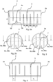
- Figure 1a and 1b disclose the device 1 for collecting particles in exhaled breath.
- Figure 1a is a cut view taken at cut B-B in figure 1b and show the inside of the device 1.
- Figure 1c visualizes the different cross section areas of the invention.
- Figure 1d is another cut view of the device.
- the device 1 comprises a housing 2 having an extension direction between a first end 2a with an inlet and a second end 2b with an outlet.
- the inlet is arranged to receive an exhaled airflow Q in comprising aerosol particles P from a subject, such as for example a person, and the outlet is arranged to transmit the exhaled airflow Q out from the device 1.
- the exhaled air is arranged to flow in a direction from the inlet to the outlet.
- the housing 2 has an inner cross section area A1 defined by inner walls 2c of the housing 2.
- the housing has an elongated cylindrical shape with a length L and a circular cross section, i.e. the cross section area A1 has an area defined by the inner diameter d1 of the housing 2.
- Figure 1d disclose another embodiment of the invention where the housing has a rectangular cross section and the cross section area A1 is defined by the height and width of the housing. Other cross section area shapes are also possible but the cross section area is always defined by the distance d between the inner walls 2c of the housing.
- the outer diameter of the housing may be of such a dimension that it can easily be fitted into a standard size test tube. I.e. it has a diameter between 8 and 30 mm, preferably between 10 and 20 mm.
- Said inner cross section area A1 is therefore slightly less than the above mentioned area, depending on the thickness of the housing walls. Therefore said cross section area A1 may be between 20 mm 2 and 615 mm 2 , preferably between 50 and 250 mm 2 , most preferably between 70 and 90 mm 2 .
- said distance d between the inner walls 2c of the housing may be between 5 and 28 mm, preferably between 8 and 18 mm, most preferably between 9,5 and 10,5 mm.
- At least four partition walls of a first type 3 is arranged to extend in a direction essentially perpendicular to the inner walls 2c, thus essentially perpendicular to the initial direction of the exhaled airflow when exiting the subjects mouth.
- Each first type partition wall 3 has a first surface 3a facing the air flow, an opposite second surface 3b and a peripheral edge 3c.
- the first and second surface 3a and 3b each have a surface area A2 smaller than the cross section area A1.
- the first type partition walls have a surface area A2 partly covering the inner cross section area A1 of the housing 2.
- the first type partitions walls may have a surface area A2 covering 50-95%, preferably 60-85%, more preferably 65-80% of the cross section area A1.
- Said first type partition walls 3 are arranged to create a labyrinth shaped flow path having a cross-sectional flow area from said inlet to said outlet.
- the airflow collides with a surface essentially perpendicular to the air flow, the flow is diverted in a direction parallel to said surface.
- Said diversion of the airflow separates the heavier particles P in the exhaled air from the air itself.
- the heavier particles P continue in the original flow direction and collide with the partition walls 3 or the housing inner wall 2a, while the air changes direction and follow the labyrinth shaped flow path. The longer distance the air flows and the more and larger direction changes the airflow is forced to do, the larger amount of particles is separated from the air and collected in the device 1.
- a direction change also creates a turbulent flow during which the particles are more easily separated from the air.
- a turbulent air also increases the impact frequency between the particles and the surfaces of the walls of the device 1, thus increasing the amount of airborne particles P attaching to the surfaces.
- the outflow Q out out of the device comprises less particles P than the inflow Q in into the device.
- a person is only able to exhale with a certain maximum flow rate Q in .
- the velum of the person closes and exhalation is impossible.
- the pressure difference over the device must therefore not be too high.
- a certain inflow Q in and pressure difference is necessary to create the certain conditions with a high enough flow velocity to separate the particles from the air flow. It is therefore important to design the device to have a certain flow path cross-sectional flow area which is defined by a first cross-sectional flow area, defined by the opening area A3 between the first type partition walls 3 and the inner walls of the housing and a second cross-sectional flow area circumscribed by the first type partition walls and the inner diameter d1 of the housing. I.e.
- the parameters defining the second cross-sectional flow area are the specific extension length L of the housing, the distance d between the inner walls 2c of the housing or inner diameter d1 of the housing and the number of first type partition walls 3 of the device 1, i.e. the distance x between the first type partition walls 3.
- the opening area A3 is preferably within the interval of 10 mm 2 - 25 mm 2 , said extension length L between 10 and 70 mm and the number of first type partition walls 3 between 4 and 14.
- the first cross-sectional flow area may be smaller than the second cross-sectional flow area. This relationship increases the acceleration of the air flowing pass the peripheral edge 3c of the first type partition wall 3.
- the first type partition walls 3 may be separated from each other with a certain distance x depending on the maximum allowed pressure difference over the device. Said distance x depends on the length L of the device and the number of first type walls 3. However, in order to create the certain conditions with a high enough flow velocity to separate the aerosol particles from the air flow, the distance x between at least two opposite first type partition walls 3 is always smaller than the distance d between the inner walls of the housing. While in figure 1a and 2a said distance x is constant, according to the invention, as shown in figure 4 , the distance between the first type partition walls 3 is increasing in the distance from the first end 2a of the device 1. I.e.
- the distance x 1 between the two opposite partition walls 3 closest to the inlet 2a is smaller than the distance x n between the two opposite partition walls 3 closest to the outlet 2b.
- the second flow path cross-sectional flow area is increasing towards the outlet 2b due to the increasing distance between the first type partition walls and the constant kept opening area A3.
- the relation between the first flow path cross-sectional flow area and the second flow path cross-sectional flow area may be kept essentially constant throughout the entire length L of the device.
- said openings 4a, 4b have the shape of circle segments, wherein the cord delimiting the circle segment is defined by the peripheral edge 3c of the first type partition wall.
- the peripheral edge 3c may be arranged as a straight line, see figure 1d , or may have an arc shape, see figures 1b, 1c , 2b and 3 .
- the device may be made of a non- absorbent material, for example polymer materials such as for example polypropylene (PP), polyvinylidene fluoride (PVDF), polytetrafluoroethylene (PTFE), fluorinated ethylene propylene (FEP) or other non-absorbent, preferably, polymer materials.
- PP polypropylene
- PVDF polyvinylidene fluoride
- PTFE polytetrafluoroethylene
- FEP fluorinated ethylene propylene
- other non-absorbent preferably, polymer materials.
- the particles may attach but are easily washed off when a later analyzing step is performed. The washing off may be performed in a test tube filled with an amount of test fluid enough to cover the entire length L of the housing.
- the housing inner wall may have a rough surface structure.
- the rough structure may be adapted to the size of the particles to be collected. I.e. if the aerosol particles to be collected have a diameter of 0.1 and 2.0 ⁇ m the inner walls may preferably be provided or covered with cavities of approximately the same size.
- the surface may also be machined to have protrusions distanced by approximately the same distance as the diameter of the particles.
- Said rough structure may also for example be a spark or electro eroded surface with a surface roughness Ra from 0.1 micron to up to 12.5 micron.
- Said possible surface roughness value also depend on the draft angle on the surface to be eroded in relation to the tool producing the eroded surface. With a larger draft angle a larger surface roughness is possible to create.
- t is also possible to further increase the surface area by providing all surfaces of the device, both inner and outer with a rough structure. Different surface roughness values are possible on different surfaces of the device 1.
- the first surface 3a and second surface 3b of the first type partition walls 3 may be directed at an angle in relation to each other such that the edge 3c of the respective first type wall 3 is narrower than the base of the first type wall.
- the first surface 3a and second surface 3b of the first type partition walls 3 may also be parallel or essentially parallel to each other, as can been seen in figure 3 .
- The may also be produced having only a small draft angle.
- Figure 2b and figures 5a-d show another example where said housing further comprises at least one second type partition wall 5.
- the second type partition wall 5 is arranged essentially parallel to the extension direction of the housing 2.
- Said at least one second type partition wall 5 extend from the first end 2a to said second end 2b of said housing creating at least two flow channels 6a-6d leading the airflow from the inlet to the outlet.
- three second type parallel partition walls 5 are shown thus four flow channels 6a-6d are created.
- Said flow channels 6a-6d have, in the example shown in figure 2b , different flow areas A6a-A6d.
- a pressure change may occur in the different channels creating different flow velocities through the different channels.
- FIG 3 another example is show where the second type partition wall or walls 5 are divided into two wall parts 5a, 5b protruding from opposite sides of the inner wall 2c of the housing 2 so that a small gap 7 is arranged between the two wall parts 5a, 5b.
- Said small gap 7 compensate for the pressure changes which may occur in the channels 6a-6d.
- the gap also contributes to a turbulent airflow in the channels.
- the device 1 comprises two device halves 1a, 1b which are adapted to be joined. When the device part 1a and 1b according to figure 4a-4d are joined they together form an elongated cylinder with a total cross section area A1.
- Each device half 1a, 1b comprises at least two first type partition walls 3 extending further than half of the total cross section A1 of the housing 2. In one example the first type partition walls 3 extend between 10% and 60% further than half of the total cross section A1 of the housing 2.
- Each housing half 1a, 1b comprises at least one partition wall of a second type 5 arranged essentially parallel to the extension direction of the housing 1 extending a maximum of half the total cross section of the housing 1.
- the second type partition walls 5 have cuttings 8 which are adapted to receive the outer ends 3c of the first type partition walls.
- the first type partition walls 3 are in one embodiment arranged to be inserted by press fitting into the cuttings 8.
Landscapes
- Health & Medical Sciences (AREA)
- Life Sciences & Earth Sciences (AREA)
- Engineering & Computer Science (AREA)
- Molecular Biology (AREA)
- Biomedical Technology (AREA)
- General Health & Medical Sciences (AREA)
- Pathology (AREA)
- Physics & Mathematics (AREA)
- Surgery (AREA)
- Heart & Thoracic Surgery (AREA)
- Medical Informatics (AREA)
- Veterinary Medicine (AREA)
- Public Health (AREA)
- Animal Behavior & Ethology (AREA)
- Biophysics (AREA)
- Chemical & Material Sciences (AREA)
- Pulmonology (AREA)
- Physiology (AREA)
- Biochemistry (AREA)
- Immunology (AREA)
- Analytical Chemistry (AREA)
- General Physics & Mathematics (AREA)
- Hematology (AREA)
- Medicinal Chemistry (AREA)
- Urology & Nephrology (AREA)
- Food Science & Technology (AREA)
- Oral & Maxillofacial Surgery (AREA)
- Nuclear Medicine, Radiotherapy & Molecular Imaging (AREA)
- Chemical Kinetics & Catalysis (AREA)
- Dentistry (AREA)
- Sampling And Sample Adjustment (AREA)
- Investigating Or Analysing Biological Materials (AREA)
- Separating Particles In Gases By Inertia (AREA)
- Medicinal Preparation (AREA)
Claims (15)
- Vorrichtung (1) zum Sammeln von Aerosolteilchen (P) in einem ausgeatmeten Luftstrom (Q), wobei die Vorrichtung Folgendes umfasst:- ein Gehäuse (2), das eine Länge (L) in einer Erstreckungsrichtung zwischen einem ersten Ende mit einem Einlass (2a), der angeordnet ist, um einen ausgeatmeten Luftstrom aufzunehmen, und einem zweiten Ende mit einem Auslass (2b), der angeordnet ist, um den ausgeatmeten Luftstrom (Q) weiterzuleiten, aufweist, wobei ein innerer Querschnitt (A1) durch eine oder mehrere innere Wände (2c) des Gehäuses (2) definiert ist, wobei der Querschnitt (A1) kreisförmig oder rechtwinklig mit einer Querbreite (d) ist und wobei das Gehäuse (2) eine längliche Form aufweist; und- mindestens vier Trennwände eines ersten Typs (3), die in einem Abstand (x) voneinander angeordnet sind und sich in eine Richtung erstrecken, die im Wesentlichen senkrecht zu der einen oder den mehreren inneren Wänden (2c) ist, den inneren Querschnitt (A1) des Gehäuses (2) teilweise bedeckend,wobei die Trennwände des ersten Typs (3) von gegenüberliegenden Seiten der einen oder der mehreren inneren Wände (2c) des Gehäuses (2) hervorstehen und gegenüberliegende Öffnungen (4a, 4b) mit einer Öffnungsfläche (A3) zwischen den Trennwänden des ersten Typs (3) und der jeweiligen gegenüberliegenden inneren Wand (2c) des Gehäuses bilden,wobei die Trennwände des ersten Typs (3) angeordnet sind, um einen labyrinthförmigen Strömungspfad zu bilden, der eine Querschnittsströmungsfläche vom Einlass (2a) zum Auslass (2b) aufweist, wobei die Trennwände des ersten Typs (3) angeordnet sind, um den ausgeatmeten Luftstrom (Q) vom Einlass (2a) hin zum Auslass (2b) in einer Richtung, die parallel zu den Trennwänden des ersten Typs (3) ist, zu der gegenüberliegenden inneren Wand (2c) des Gehäuses hin umzuleiten, sodass Aerosolteilchen (P) in dem ausgeatmeten Luftstrom (Q) mit den Trennwänden des ersten Typs (3) und/oder den inneren Wänden (2c) kollidieren und an der Vorrichtung (1) haften,wobei der Abstand (x) zwischen zwei gegenüberliegenden Trennwänden des ersten Typs (3) kleiner ist als die Querbreite (d) des Querschnitts (A1),dadurch gekennzeichnet, dass der Abstand (x1, ..., xn) zwischen gegenüberliegenden Trennwänden des ersten Typs (3) in der Erstreckungsrichtung des Gehäuses (2) vom Einlass (2a) zunimmt.
- Vorrichtung nach Anspruch 1, wobei jede Trennwand des ersten Typs (3) eine Trennfläche (A2) aufweist, die im Wesentlichen senkrecht zur Längserstreckungsrichtung des Gehäuses (2) ist, bedeckend 50-59 %, vorzugsweise 60-85 %, bevorzugter 65-80 % der inneren Querschnittsfläche (A1) des Gehäuses.
- Vorrichtung nach Anspruch 1 oder 2, wobei die innere Querschnittsfläche (A1) zwischen 20 mm2 und 615 mm2, vorzugsweise zwischen 50 und 250 mm2, besonders bevorzugt zwischen 70 und 90 mm2 beträgt.
- Vorrichtung nach einem der vorstehenden Ansprüche, wobei die Öffnungsfläche (A3) zwischen den Trennwänden des ersten Typs (3) und der jeweiligen gegenüberliegenden inneren Wand (2c) des Gehäuses näher am Auslass (2b) allmählich zunimmt.
- Vorrichtung nach einem der vorstehenden Ansprüche, wobei die Öffnungsfläche (A3) eine erste Querschnittsströmungsfläche definiert, und die Trennwände des ersten Typs (3) und die Querbreite (d) oder Innendurchmesser (d1) des Gehäuses eine zweite Querschnittsströmungsfläche umschreiben, wobei das Verhältnis zwischen der ersten Querschnittsströmungsfläche und der zweiten Querschnittsströmungsfläche über die gesamte Länge der Vorrichtung im Wesentlichen konstant bleibt.
- Vorrichtung nach einem der vorstehenden Ansprüche, wobei die Öffnungsfläche (A3) innerhalb des Intervalls von 10 mm2-25 mm2 liegt, die Länge (L) zwischen 10 und 70 mm beträgt und die Anzahl der Trennwände des ersten Typs (3) zwischen 4 und 14 ist.
- Vorrichtung nach einem der vorstehenden Ansprüche, wobei das Gehäuse (2) mindestens eine Trennwand des zweiten Typs (5) umfasst, die im Wesentlichen parallel zu der Erstreckungsrichtung des Gehäuses (2) angeordnet ist.
- Vorrichtung nach einem der vorstehenden Ansprüche, wobei das Gehäuse (2) die Form eines länglichen Zylinders mit einem kreisförmigen Querschnitt aufweist.
- Vorrichtung nach Anspruch 8, wobei das Gehäuse so dimensioniert ist, dass es in eine Teströhre passt.
- Vorrichtung nach einem der Ansprüche 1-7, wobei das Gehäuse (2) einen rechtwinkligen Querschnitt aufweist,
- Vorrichtung nach einem der vorstehenden Ansprüche, wobei die Vorrichtung aus einem nichtabsorbierenden Material hergestellt ist.
- Vorrichtung nach einem der vorstehenden Ansprüche, wobei mindestens eines der folgenden Teile eine raue Oberflächenstruktur aufweist, um die Oberfläche zu vergrößern; Gehäuse (2), Trennwände des ersten Typs (3).
- Vorrichtung nach einem der vorstehenden Ansprüche, wobei das Gehäuse (2) eine erste und zweite Gehäusehälfte (1a, 1b) umfasst, die angepasst sind, um zusammengefügt zu werden, wobei jede Gehäusehälfte (1a, 1b) mindesten zwei Trennwände des ersten Typs (3) umfasst, die sich über mehr als die Hälfte des Querschnitts (A1) des Gehäuses erstrecken.
- Vorrichtung nach Anspruch 13, wobei jede Gehäusehälfte (1a, 1b) mindestens eine Trennwand des zweiten Typs (5), im Wesentlichen parallel zur Längserstreckungsrichtung des Gehäuses (2) angeordnet, umfasst, die sich über maximal die Hälfte des Querschnitts (A1) des Gehäuses (2) erstreckt.
- Vorrichtung nach Anspruch 15, wobei die mindestens eine Trennwand des zweiten Typs (5) mindestens zwei Aussparungen (8) aufweist, in denen die mindestens zwei Trennwände des ersten Typs (3) angeordnet sind, um eingefügt zu werden.
Applications Claiming Priority (3)
| Application Number | Priority Date | Filing Date | Title |
|---|---|---|---|
| SE1550930A SE540830C2 (en) | 2015-07-01 | 2015-07-01 | Device for collecting aerosol particles in an exhaled airflow |
| EP16729925.4A EP3316778B1 (de) | 2015-07-01 | 2016-06-19 | Vorrichtung zum auffangen von partikeln in ausatemluftstrom |
| PCT/EP2016/064110 WO2017001217A1 (en) | 2015-07-01 | 2016-06-19 | A device for collecting particles in an exhaled airflow |
Related Parent Applications (2)
| Application Number | Title | Priority Date | Filing Date |
|---|---|---|---|
| EP16729925.4A Division EP3316778B1 (de) | 2015-07-01 | 2016-06-19 | Vorrichtung zum auffangen von partikeln in ausatemluftstrom |
| EP16729925.4A Division-Into EP3316778B1 (de) | 2015-07-01 | 2016-06-19 | Vorrichtung zum auffangen von partikeln in ausatemluftstrom |
Publications (3)
| Publication Number | Publication Date |
|---|---|
| EP3973867A1 EP3973867A1 (de) | 2022-03-30 |
| EP3973867B1 true EP3973867B1 (de) | 2024-05-22 |
| EP3973867C0 EP3973867C0 (de) | 2024-05-22 |
Family
ID=56134370
Family Applications (2)
| Application Number | Title | Priority Date | Filing Date |
|---|---|---|---|
| EP16729925.4A Active EP3316778B1 (de) | 2015-07-01 | 2016-06-19 | Vorrichtung zum auffangen von partikeln in ausatemluftstrom |
| EP21208236.6A Active EP3973867B1 (de) | 2015-07-01 | 2016-06-19 | Vorrichtung zum auffangen von partikeln in ausatemluftstrom |
Family Applications Before (1)
| Application Number | Title | Priority Date | Filing Date |
|---|---|---|---|
| EP16729925.4A Active EP3316778B1 (de) | 2015-07-01 | 2016-06-19 | Vorrichtung zum auffangen von partikeln in ausatemluftstrom |
Country Status (11)
| Country | Link |
|---|---|
| US (3) | US10898108B2 (de) |
| EP (2) | EP3316778B1 (de) |
| CN (2) | CN107735023B (de) |
| AU (1) | AU2016288362B2 (de) |
| CA (1) | CA2990504C (de) |
| DK (1) | DK3316778T3 (de) |
| ES (1) | ES2910524T3 (de) |
| PL (1) | PL3316778T3 (de) |
| PT (1) | PT3316778T (de) |
| SE (1) | SE540830C2 (de) |
| WO (1) | WO2017001217A1 (de) |
Families Citing this family (10)
| Publication number | Priority date | Publication date | Assignee | Title |
|---|---|---|---|---|
| SE540830C2 (en) * | 2015-07-01 | 2018-11-27 | Munkplast Ab | Device for collecting aerosol particles in an exhaled airflow |
| SE541748C2 (en) | 2017-07-10 | 2019-12-10 | Pexa Ab | System for collecting exhaled particles |
| CA3115674C (en) | 2018-10-12 | 2023-11-07 | David Henderson | Ndir sensor, sampling method and system for breath analysis |
| WO2020145896A1 (en) * | 2019-01-11 | 2020-07-16 | National University Of Singapore | Sample collection device |
| WO2022079195A1 (en) * | 2020-10-14 | 2022-04-21 | Imec Vzw | A collecting device for collection of particles, a sample collector, and an analysis instrument |
| CN112742118B (zh) * | 2020-12-11 | 2022-08-12 | 西安增材制造国家研究院有限公司 | 一种用于电子束3d打印系统的真空过滤器 |
| CN114343723B (zh) * | 2021-12-22 | 2022-11-22 | 北京华泰诺安技术有限公司 | 非侵入式同时收集人体呼出气溶胶与气体的系统及方法 |
| US20230191306A1 (en) * | 2021-12-22 | 2023-06-22 | Sdi Diagnostics, Inc. | Breathing tube filter and filter assembly |
| SE547329C2 (en) * | 2022-06-03 | 2025-07-01 | Munkplast Ab | Method and system for preparing a breath sample for analysis |
| EP4583772A1 (de) | 2022-09-09 | 2025-07-16 | Munkplast AB | Vorrichtung zum sammeln von partikeln in einem ausgeatmeten luftstrom und verfahren zur extraktion gesammelter partikel |
Family Cites Families (25)
| Publication number | Priority date | Publication date | Assignee | Title |
|---|---|---|---|---|
| US1803854A (en) | 1926-10-14 | 1931-05-05 | Atmospheric Nitrogen Corp | Method of separating finely divided liquids from gases and apparatus therefor |
| US3953182A (en) | 1974-09-03 | 1976-04-27 | Roth Thomas P | Collection medium for air sampler |
| US4292978A (en) * | 1979-12-26 | 1981-10-06 | Guth Richard U | Breath test mouthpiece |
| US5193551A (en) * | 1990-07-27 | 1993-03-16 | Pilipski M | Phantom assembly to verify accuracy of a carbon monoxide diffusing capacity measuring device |
| AUPM765994A0 (en) * | 1994-08-26 | 1994-09-15 | University Of Sydney, The | Nasal filters |
| US7578973B2 (en) * | 1998-11-13 | 2009-08-25 | Mesosystems Technology, Inc. | Devices for continuous sampling of airborne particles using a regenerative surface |
| RU2166341C1 (ru) * | 1999-12-10 | 2001-05-10 | Общество с ограниченной ответственностью "Алгоритм" | Дыхательный фильтр |
| SE524138C2 (sv) * | 2002-11-05 | 2004-07-06 | Anders Evensson | Anordningsskydd |
| US8722417B2 (en) * | 2003-04-28 | 2014-05-13 | Invoy Technologies, L.L.C. | Thermoelectric sensor for analytes in a fluid and related method |
| EP1718874A4 (de) | 2004-02-09 | 2009-12-30 | Indigo Technologies Group Pty | Verbesserte partikel-wechselwirkungen in einem fluidstrom |
| US7258716B2 (en) * | 2004-03-22 | 2007-08-21 | Joseph Gerard Birmingham | Microimpactor system having optimized impactor spacing |
| GB0504312D0 (en) * | 2005-03-02 | 2005-04-06 | Boc Group Plc | Trap device |
| CA2701352A1 (en) * | 2007-10-02 | 2009-04-09 | Ann-Charlotte Almstrand | Collection and measurement of exhaled particles |
| SE535611C2 (sv) * | 2010-06-24 | 2012-10-16 | Nose Option Ab | Näsplugg |
| EP2518499B1 (de) | 2011-03-09 | 2015-06-10 | Sensa Bues AB | Tragbare Probenahmevorrichtung und Verfahren für den Nachweis von Drogen in der Ausatemluft |
| WO2013132085A1 (en) * | 2012-03-08 | 2013-09-12 | Sensa Bues Ab | A portable sampling device and method for detection of biomarkers in exhaled breath |
| EP2687156B1 (de) * | 2012-07-18 | 2019-03-20 | Bedfont Scientific Limited | Gassensorvorrichtung |
| FR3004916B1 (fr) * | 2013-04-30 | 2015-04-17 | France Internat Medical | Systeme et dispositif pour la mesure d’un debit d’un flux d’air expire ou inspire |
| US9438370B2 (en) | 2014-05-19 | 2016-09-06 | Ciena Corporation | Margin-based optimization systems and methods in optical networks to unblock superchannels |
| US20160345894A1 (en) * | 2015-05-29 | 2016-12-01 | Bohnas LLC | Method of Sampling Systemic Biomarkers |
| SE541088C2 (en) * | 2015-11-24 | 2019-04-02 | Munkplast Ab | Portable sampling device for collecting particles from exhaled breath |
| SE540830C2 (en) * | 2015-07-01 | 2018-11-27 | Munkplast Ab | Device for collecting aerosol particles in an exhaled airflow |
| WO2018098483A1 (en) * | 2016-11-28 | 2018-05-31 | Spirosure, Inc. | Handpiece for respiratory monitor |
| GB201700845D0 (en) * | 2017-01-18 | 2017-03-01 | Turbinate Tech Ltd | Apparatus for removal of particulates from air |
| KR102558323B1 (ko) * | 2018-12-13 | 2023-07-20 | 다이아그노스 얼리, 인크. | 휘발성 유기 화합물 수집을 위한 디바이스, 방법 및 시스템 |
-
2015
- 2015-07-01 SE SE1550930A patent/SE540830C2/en not_active IP Right Cessation
-
2016
- 2016-06-19 DK DK16729925.4T patent/DK3316778T3/da active
- 2016-06-19 AU AU2016288362A patent/AU2016288362B2/en active Active
- 2016-06-19 WO PCT/EP2016/064110 patent/WO2017001217A1/en not_active Ceased
- 2016-06-19 CN CN201680036256.5A patent/CN107735023B/zh active Active
- 2016-06-19 EP EP16729925.4A patent/EP3316778B1/de active Active
- 2016-06-19 CN CN202111073631.2A patent/CN113995441B/zh active Active
- 2016-06-19 PT PT167299254T patent/PT3316778T/pt unknown
- 2016-06-19 ES ES16729925T patent/ES2910524T3/es active Active
- 2016-06-19 PL PL16729925T patent/PL3316778T3/pl unknown
- 2016-06-19 CA CA2990504A patent/CA2990504C/en active Active
- 2016-06-19 EP EP21208236.6A patent/EP3973867B1/de active Active
-
2017
- 2017-12-28 US US15/856,090 patent/US10898108B2/en active Active
-
2020
- 2020-03-06 US US16/811,162 patent/US11701030B2/en active Active
-
2021
- 2021-01-25 US US17/156,688 patent/US11730393B2/en active Active
Also Published As
| Publication number | Publication date |
|---|---|
| NZ738449A (en) | 2023-09-29 |
| CA2990504C (en) | 2023-08-15 |
| AU2016288362A1 (en) | 2018-01-18 |
| US11701030B2 (en) | 2023-07-18 |
| CN113995441A (zh) | 2022-02-01 |
| US11730393B2 (en) | 2023-08-22 |
| EP3973867A1 (de) | 2022-03-30 |
| CN113995441B (zh) | 2025-04-04 |
| PT3316778T (pt) | 2022-04-14 |
| US10898108B2 (en) | 2021-01-26 |
| EP3973867C0 (de) | 2024-05-22 |
| CA2990504A1 (en) | 2017-01-05 |
| US20180116640A1 (en) | 2018-05-03 |
| AU2016288362B2 (en) | 2020-06-11 |
| EP3316778A1 (de) | 2018-05-09 |
| SE540830C2 (en) | 2018-11-27 |
| ES2910524T3 (es) | 2022-05-12 |
| US20200268280A1 (en) | 2020-08-27 |
| CN107735023A (zh) | 2018-02-23 |
| CN107735023B (zh) | 2021-09-14 |
| PL3316778T3 (pl) | 2022-05-30 |
| US20210137415A1 (en) | 2021-05-13 |
| SE1550930A1 (en) | 2017-01-02 |
| HK1252193A1 (zh) | 2019-05-24 |
| DK3316778T3 (da) | 2022-04-11 |
| EP3316778B1 (de) | 2022-01-19 |
| WO2017001217A1 (en) | 2017-01-05 |
Similar Documents
| Publication | Publication Date | Title |
|---|---|---|
| EP3973867B1 (de) | Vorrichtung zum auffangen von partikeln in ausatemluftstrom | |
| CN103814294B (zh) | 用于从呼出气体采样药物物质的便携式采样装置及方法 | |
| EP3380010B1 (de) | Tragbare probenahmevorrichtung, ständer und verfahren zur entnahme von partikeln aus ausgeatmeter luft | |
| US5857461A (en) | Multiple channel sample port | |
| EP3849414B1 (de) | Atemprobenahmevorrichtung | |
| US10359417B2 (en) | Portable sampling device and method for detection of biomarkers in exhaled breath | |
| HK1252193B (en) | A device for collecting particles in an exhaled airflow | |
| EP4583772A1 (de) | Vorrichtung zum sammeln von partikeln in einem ausgeatmeten luftstrom und verfahren zur extraktion gesammelter partikel | |
| KR100464161B1 (ko) | 호흡성 분진 포집장치 | |
| NZ738449B2 (en) | A device for collecting particles in an exhaled airflow | |
| HK1256236B (en) | Portable sampling device, stand and method for collecting particles from exhaled breath |
Legal Events
| Date | Code | Title | Description |
|---|---|---|---|
| PUAI | Public reference made under article 153(3) epc to a published international application that has entered the european phase |
Free format text: ORIGINAL CODE: 0009012 |
|
| STAA | Information on the status of an ep patent application or granted ep patent |
Free format text: STATUS: THE APPLICATION HAS BEEN PUBLISHED |
|
| AC | Divisional application: reference to earlier application |
Ref document number: 3316778 Country of ref document: EP Kind code of ref document: P |
|
| AK | Designated contracting states |
Kind code of ref document: A1 Designated state(s): AL AT BE BG CH CY CZ DE DK EE ES FI FR GB GR HR HU IE IS IT LI LT LU LV MC MK MT NL NO PL PT RO RS SE SI SK SM TR |
|
| STAA | Information on the status of an ep patent application or granted ep patent |
Free format text: STATUS: REQUEST FOR EXAMINATION WAS MADE |
|
| 17P | Request for examination filed |
Effective date: 20220928 |
|
| RBV | Designated contracting states (corrected) |
Designated state(s): AL AT BE BG CH CY CZ DE DK EE ES FI FR GB GR HR HU IE IS IT LI LT LU LV MC MK MT NL NO PL PT RO RS SE SI SK SM TR |
|
| GRAP | Despatch of communication of intention to grant a patent |
Free format text: ORIGINAL CODE: EPIDOSNIGR1 |
|
| STAA | Information on the status of an ep patent application or granted ep patent |
Free format text: STATUS: GRANT OF PATENT IS INTENDED |
|
| RIC1 | Information provided on ipc code assigned before grant |
Ipc: A61B 10/00 20060101ALN20231101BHEP Ipc: G01N 1/22 20060101ALI20231101BHEP Ipc: G01N 33/497 20060101ALI20231101BHEP Ipc: A61B 5/097 20060101AFI20231101BHEP |
|
| INTG | Intention to grant announced |
Effective date: 20231117 |
|
| GRAJ | Information related to disapproval of communication of intention to grant by the applicant or resumption of examination proceedings by the epo deleted |
Free format text: ORIGINAL CODE: EPIDOSDIGR1 |
|
| STAA | Information on the status of an ep patent application or granted ep patent |
Free format text: STATUS: REQUEST FOR EXAMINATION WAS MADE |
|
| INTC | Intention to grant announced (deleted) | ||
| GRAP | Despatch of communication of intention to grant a patent |
Free format text: ORIGINAL CODE: EPIDOSNIGR1 |
|
| STAA | Information on the status of an ep patent application or granted ep patent |
Free format text: STATUS: GRANT OF PATENT IS INTENDED |
|
| GRAS | Grant fee paid |
Free format text: ORIGINAL CODE: EPIDOSNIGR3 |
|
| GRAA | (expected) grant |
Free format text: ORIGINAL CODE: 0009210 |
|
| STAA | Information on the status of an ep patent application or granted ep patent |
Free format text: STATUS: THE PATENT HAS BEEN GRANTED |
|
| INTG | Intention to grant announced |
Effective date: 20240405 |
|
| RIC1 | Information provided on ipc code assigned before grant |
Ipc: A61B 10/00 20060101ALN20240322BHEP Ipc: G01N 1/22 20060101ALI20240322BHEP Ipc: G01N 33/497 20060101ALI20240322BHEP Ipc: A61B 5/097 20060101AFI20240322BHEP |
|
| AC | Divisional application: reference to earlier application |
Ref document number: 3316778 Country of ref document: EP Kind code of ref document: P |
|
| AK | Designated contracting states |
Kind code of ref document: B1 Designated state(s): AL AT BE BG CH CY CZ DE DK EE ES FI FR GB GR HR HU IE IS IT LI LT LU LV MC MK MT NL NO PL PT RO RS SE SI SK SM TR |
|
| REG | Reference to a national code |
Ref country code: GB Ref legal event code: FG4D |
|
| REG | Reference to a national code |
Ref country code: CH Ref legal event code: EP |
|
| REG | Reference to a national code |
Ref country code: DE Ref legal event code: R096 Ref document number: 602016087698 Country of ref document: DE |
|
| REG | Reference to a national code |
Ref country code: IE Ref legal event code: FG4D |
|
| U01 | Request for unitary effect filed |
Effective date: 20240613 |
|
| U07 | Unitary effect registered |
Designated state(s): AT BE BG DE DK EE FI FR IT LT LU LV MT NL PT SE SI Effective date: 20240624 |
|
| U20 | Renewal fee for the european patent with unitary effect paid |
Year of fee payment: 9 Effective date: 20240828 |
|
| PG25 | Lapsed in a contracting state [announced via postgrant information from national office to epo] |
Ref country code: IS Free format text: LAPSE BECAUSE OF FAILURE TO SUBMIT A TRANSLATION OF THE DESCRIPTION OR TO PAY THE FEE WITHIN THE PRESCRIBED TIME-LIMIT Effective date: 20240922 |
|
| PG25 | Lapsed in a contracting state [announced via postgrant information from national office to epo] |
Ref country code: HR Free format text: LAPSE BECAUSE OF FAILURE TO SUBMIT A TRANSLATION OF THE DESCRIPTION OR TO PAY THE FEE WITHIN THE PRESCRIBED TIME-LIMIT Effective date: 20240522 |
|
| PG25 | Lapsed in a contracting state [announced via postgrant information from national office to epo] |
Ref country code: GR Free format text: LAPSE BECAUSE OF FAILURE TO SUBMIT A TRANSLATION OF THE DESCRIPTION OR TO PAY THE FEE WITHIN THE PRESCRIBED TIME-LIMIT Effective date: 20240823 |
|
| PG25 | Lapsed in a contracting state [announced via postgrant information from national office to epo] |
Ref country code: ES Free format text: LAPSE BECAUSE OF FAILURE TO SUBMIT A TRANSLATION OF THE DESCRIPTION OR TO PAY THE FEE WITHIN THE PRESCRIBED TIME-LIMIT Effective date: 20240522 |
|
| PG25 | Lapsed in a contracting state [announced via postgrant information from national office to epo] |
Ref country code: PL Free format text: LAPSE BECAUSE OF FAILURE TO SUBMIT A TRANSLATION OF THE DESCRIPTION OR TO PAY THE FEE WITHIN THE PRESCRIBED TIME-LIMIT Effective date: 20240522 |
|
| PG25 | Lapsed in a contracting state [announced via postgrant information from national office to epo] |
Ref country code: PL Free format text: LAPSE BECAUSE OF FAILURE TO SUBMIT A TRANSLATION OF THE DESCRIPTION OR TO PAY THE FEE WITHIN THE PRESCRIBED TIME-LIMIT Effective date: 20240522 Ref country code: NO Free format text: LAPSE BECAUSE OF FAILURE TO SUBMIT A TRANSLATION OF THE DESCRIPTION OR TO PAY THE FEE WITHIN THE PRESCRIBED TIME-LIMIT Effective date: 20240822 Ref country code: IS Free format text: LAPSE BECAUSE OF FAILURE TO SUBMIT A TRANSLATION OF THE DESCRIPTION OR TO PAY THE FEE WITHIN THE PRESCRIBED TIME-LIMIT Effective date: 20240922 Ref country code: HR Free format text: LAPSE BECAUSE OF FAILURE TO SUBMIT A TRANSLATION OF THE DESCRIPTION OR TO PAY THE FEE WITHIN THE PRESCRIBED TIME-LIMIT Effective date: 20240522 Ref country code: GR Free format text: LAPSE BECAUSE OF FAILURE TO SUBMIT A TRANSLATION OF THE DESCRIPTION OR TO PAY THE FEE WITHIN THE PRESCRIBED TIME-LIMIT Effective date: 20240823 Ref country code: ES Free format text: LAPSE BECAUSE OF FAILURE TO SUBMIT A TRANSLATION OF THE DESCRIPTION OR TO PAY THE FEE WITHIN THE PRESCRIBED TIME-LIMIT Effective date: 20240522 Ref country code: RS Free format text: LAPSE BECAUSE OF FAILURE TO SUBMIT A TRANSLATION OF THE DESCRIPTION OR TO PAY THE FEE WITHIN THE PRESCRIBED TIME-LIMIT Effective date: 20240822 |
|
| PG25 | Lapsed in a contracting state [announced via postgrant information from national office to epo] |
Ref country code: CZ Free format text: LAPSE BECAUSE OF FAILURE TO SUBMIT A TRANSLATION OF THE DESCRIPTION OR TO PAY THE FEE WITHIN THE PRESCRIBED TIME-LIMIT Effective date: 20240522 |
|
| PG25 | Lapsed in a contracting state [announced via postgrant information from national office to epo] |
Ref country code: SK Free format text: LAPSE BECAUSE OF FAILURE TO SUBMIT A TRANSLATION OF THE DESCRIPTION OR TO PAY THE FEE WITHIN THE PRESCRIBED TIME-LIMIT Effective date: 20240522 Ref country code: RO Free format text: LAPSE BECAUSE OF FAILURE TO SUBMIT A TRANSLATION OF THE DESCRIPTION OR TO PAY THE FEE WITHIN THE PRESCRIBED TIME-LIMIT Effective date: 20240522 |
|
| PG25 | Lapsed in a contracting state [announced via postgrant information from national office to epo] |
Ref country code: SK Free format text: LAPSE BECAUSE OF FAILURE TO SUBMIT A TRANSLATION OF THE DESCRIPTION OR TO PAY THE FEE WITHIN THE PRESCRIBED TIME-LIMIT Effective date: 20240522 Ref country code: RO Free format text: LAPSE BECAUSE OF FAILURE TO SUBMIT A TRANSLATION OF THE DESCRIPTION OR TO PAY THE FEE WITHIN THE PRESCRIBED TIME-LIMIT Effective date: 20240522 Ref country code: CZ Free format text: LAPSE BECAUSE OF FAILURE TO SUBMIT A TRANSLATION OF THE DESCRIPTION OR TO PAY THE FEE WITHIN THE PRESCRIBED TIME-LIMIT Effective date: 20240522 |
|
| REG | Reference to a national code |
Ref country code: CH Ref legal event code: PL |
|
| PG25 | Lapsed in a contracting state [announced via postgrant information from national office to epo] |
Ref country code: MC Free format text: LAPSE BECAUSE OF FAILURE TO SUBMIT A TRANSLATION OF THE DESCRIPTION OR TO PAY THE FEE WITHIN THE PRESCRIBED TIME-LIMIT Effective date: 20240522 |
|
| REG | Reference to a national code |
Ref country code: DE Ref legal event code: R097 Ref document number: 602016087698 Country of ref document: DE |
|
| PLBE | No opposition filed within time limit |
Free format text: ORIGINAL CODE: 0009261 |
|
| STAA | Information on the status of an ep patent application or granted ep patent |
Free format text: STATUS: NO OPPOSITION FILED WITHIN TIME LIMIT |
|
| PG25 | Lapsed in a contracting state [announced via postgrant information from national office to epo] |
Ref country code: IE Free format text: LAPSE BECAUSE OF NON-PAYMENT OF DUE FEES Effective date: 20240619 |
|
| PG25 | Lapsed in a contracting state [announced via postgrant information from national office to epo] |
Ref country code: CH Free format text: LAPSE BECAUSE OF NON-PAYMENT OF DUE FEES Effective date: 20240630 |
|
| 26N | No opposition filed |
Effective date: 20250225 |
|
| PGFP | Annual fee paid to national office [announced via postgrant information from national office to epo] |
Ref country code: GB Payment date: 20250618 Year of fee payment: 10 |
|
| U20 | Renewal fee for the european patent with unitary effect paid |
Year of fee payment: 10 Effective date: 20250617 |
|
| PG25 | Lapsed in a contracting state [announced via postgrant information from national office to epo] |
Ref country code: SM Free format text: LAPSE BECAUSE OF FAILURE TO SUBMIT A TRANSLATION OF THE DESCRIPTION OR TO PAY THE FEE WITHIN THE PRESCRIBED TIME-LIMIT; INVALID AB INITIO Effective date: 20160619 |
|
| PG25 | Lapsed in a contracting state [announced via postgrant information from national office to epo] |
Ref country code: CY Free format text: LAPSE BECAUSE OF FAILURE TO SUBMIT A TRANSLATION OF THE DESCRIPTION OR TO PAY THE FEE WITHIN THE PRESCRIBED TIME-LIMIT; INVALID AB INITIO Effective date: 20160619 |