EP3973354B1 - Procédé et dispositif de commande de moteurs dans le secteur du film et de la radiodiffusion - Google Patents
Procédé et dispositif de commande de moteurs dans le secteur du film et de la radiodiffusion Download PDFInfo
- Publication number
- EP3973354B1 EP3973354B1 EP20726322.9A EP20726322A EP3973354B1 EP 3973354 B1 EP3973354 B1 EP 3973354B1 EP 20726322 A EP20726322 A EP 20726322A EP 3973354 B1 EP3973354 B1 EP 3973354B1
- Authority
- EP
- European Patent Office
- Prior art keywords
- operating element
- force
- handwheel
- control unit
- processing unit
- Prior art date
- Legal status (The legal status is an assumption and is not a legal conclusion. Google has not performed a legal analysis and makes no representation as to the accuracy of the status listed.)
- Active
Links
Images

Classifications
-
- G—PHYSICS
- G03—PHOTOGRAPHY; CINEMATOGRAPHY; ANALOGOUS TECHNIQUES USING WAVES OTHER THAN OPTICAL WAVES; ELECTROGRAPHY; HOLOGRAPHY
- G03B—APPARATUS OR ARRANGEMENTS FOR TAKING PHOTOGRAPHS OR FOR PROJECTING OR VIEWING THEM; APPARATUS OR ARRANGEMENTS EMPLOYING ANALOGOUS TECHNIQUES USING WAVES OTHER THAN OPTICAL WAVES; ACCESSORIES THEREFOR
- G03B17/00—Details of cameras or camera bodies; Accessories therefor
- G03B17/56—Accessories
-
- G—PHYSICS
- G03—PHOTOGRAPHY; CINEMATOGRAPHY; ANALOGOUS TECHNIQUES USING WAVES OTHER THAN OPTICAL WAVES; ELECTROGRAPHY; HOLOGRAPHY
- G03B—APPARATUS OR ARRANGEMENTS FOR TAKING PHOTOGRAPHS OR FOR PROJECTING OR VIEWING THEM; APPARATUS OR ARRANGEMENTS EMPLOYING ANALOGOUS TECHNIQUES USING WAVES OTHER THAN OPTICAL WAVES; ACCESSORIES THEREFOR
- G03B13/00—Viewfinders; Focusing aids for cameras; Means for focusing for cameras; Autofocus systems for cameras
- G03B13/18—Focusing aids
-
- G—PHYSICS
- G03—PHOTOGRAPHY; CINEMATOGRAPHY; ANALOGOUS TECHNIQUES USING WAVES OTHER THAN OPTICAL WAVES; ELECTROGRAPHY; HOLOGRAPHY
- G03B—APPARATUS OR ARRANGEMENTS FOR TAKING PHOTOGRAPHS OR FOR PROJECTING OR VIEWING THEM; APPARATUS OR ARRANGEMENTS EMPLOYING ANALOGOUS TECHNIQUES USING WAVES OTHER THAN OPTICAL WAVES; ACCESSORIES THEREFOR
- G03B13/00—Viewfinders; Focusing aids for cameras; Means for focusing for cameras; Autofocus systems for cameras
- G03B13/32—Means for focusing
- G03B13/34—Power focusing
-
- G—PHYSICS
- G03—PHOTOGRAPHY; CINEMATOGRAPHY; ANALOGOUS TECHNIQUES USING WAVES OTHER THAN OPTICAL WAVES; ELECTROGRAPHY; HOLOGRAPHY
- G03B—APPARATUS OR ARRANGEMENTS FOR TAKING PHOTOGRAPHS OR FOR PROJECTING OR VIEWING THEM; APPARATUS OR ARRANGEMENTS EMPLOYING ANALOGOUS TECHNIQUES USING WAVES OTHER THAN OPTICAL WAVES; ACCESSORIES THEREFOR
- G03B17/00—Details of cameras or camera bodies; Accessories therefor
- G03B17/02—Bodies
-
- G—PHYSICS
- G03—PHOTOGRAPHY; CINEMATOGRAPHY; ANALOGOUS TECHNIQUES USING WAVES OTHER THAN OPTICAL WAVES; ELECTROGRAPHY; HOLOGRAPHY
- G03B—APPARATUS OR ARRANGEMENTS FOR TAKING PHOTOGRAPHS OR FOR PROJECTING OR VIEWING THEM; APPARATUS OR ARRANGEMENTS EMPLOYING ANALOGOUS TECHNIQUES USING WAVES OTHER THAN OPTICAL WAVES; ACCESSORIES THEREFOR
- G03B17/00—Details of cameras or camera bodies; Accessories therefor
- G03B17/18—Signals indicating condition of a camera member or suitability of light
-
- G—PHYSICS
- G06—COMPUTING OR CALCULATING; COUNTING
- G06F—ELECTRIC DIGITAL DATA PROCESSING
- G06F3/00—Input arrangements for transferring data to be processed into a form capable of being handled by the computer; Output arrangements for transferring data from processing unit to output unit, e.g. interface arrangements
- G06F3/01—Input arrangements or combined input and output arrangements for interaction between user and computer
- G06F3/016—Input arrangements with force or tactile feedback as computer generated output to the user
Definitions
- the invention relates to a method for controlling or regulating motors in the film and broadcast sector according to the preamble of claim 1 or 2, as well as a device for carrying out the method according to the preamble of claim 14 or 15.
- focus, aperture and zoom have usually been controlled electronically using external motors attached to the lens of a camera.
- a hand-held control device which usually has a handwheel for the focus, a slider for the aperture and possibly a type of joystick for the zoom setting, the user can control up to three motors attached to the lens from a distance, each of which then controls the focus, aperture and possibly zoom.
- Data is usually transmitted wirelessly.
- the input devices usually have potentiometers or incremental encoders, which, for example, record the respective position of the handwheel and pass it on to the motors.
- Such an input device usually has two fixed end stops. As part of a calibration, these end stops are assigned to the end stops of the lens, i.e.
- the rotation range of just under one revolution is assigned to the rotation range of the lens.
- a small area of the lens can also be assigned to the entire rotation range of the input device in order to be able to control even more precisely ( DE 10 2004 015 947 A1 ).
- remote heads tilt camera heads
- camera cranes which are controlled via either joysticks, sliders or handwheels.
- a hand control unit with haptic feedback is also available EP2706407A and WO9725657A known.
- Another problem is that the user only receives visual feedback via a display, but no haptic feedback.
- a system known that activates a small motor with an imbalance when a certain mark is reached, causing the entire hand control unit to vibrate ARRI WCU-4 Wireless Compact Unit, USER MANUAL from December 12, 2018 ).
- This has two disadvantages: The handwheel itself does not vibrate, but the entire device; it is therefore not very intuitive and feels alien or not related to the respective axis (e.g. focus, iris, zoom).
- it is difficult to move to the intended position precisely, since the reaction time of the It is too slow for people when making quick control movements.
- it can only signal the marking of a single axis, because if the entire device vibrates, it is not possible to determine which axis is actually involved when there are several axes.
- adjustable friction of the adjustment device can only be set uniformly for the entire control element mechanically by changing a lock nut.
- Another problem concerns the assignment of real input values to the position of the input device.
- DE 197 12 049 A1 describes an operating device for manual input of information into a device.
- the US 2003 / 0184.518 A1 describes a device with haptic feedback, which consists of an operating unit, a drive element generating the haptic feedback and a control unit for the drive element.
- the DE 10 2015 110 633 A1 discloses a haptic operating unit and a method for operating vehicles, wherein a haptic operating device with a rotary unit is used and selectable menu items are displayed on a display unit, and wherein a menu item is selected by rotating the rotary unit.
- the US 2007 / 027 9401 A1 describes a system and method for rotary motion in a hybrid haptic device consisting of a knob rotatably mounted on a base plate via a shaft.
- the present invention relates to the control or regulation of motors via radio or cable, at least indirectly, for movement axes of devices in the film or broadcast sector consisting of a computer unit and an operating unit, such as a handheld unit.
- the movement axes are defined on a mechanism by two limits/end stops.
- the operating unit consists of at least one operating element with a built-in electromechanical element that can generate dynamic haptic feedback on this operating element.
- the operating element can be a handwheel or a slider.
- the electromagnetic element is, for example, a brushless motor that can exert a force on the operating element via a gear, using entered or read parameters, can be dynamically changed and can also be manually overridden.
- a parameter can be the distance of an object from the recording camera, but also a change in the state of the object, e.g. a balloon bursting, where the focus should be on another object at that moment.
- the invention provides that the handwheel is equipped with a suitable motor and, ideally, angle of rotation sensors for the incremental or absolute position of the handwheel.
- This force on the handwheel should be dynamically adjustable using parameters entered or read from other devices or motors.
- “Dynamic” is also understood to mean that a certain state of the force on the handwheel does not have to change over a certain period of time, but can nevertheless change and be transferred to another state at any time without mechanical intervention by the user (i.e. without adjusting the friction of a handwheel using an adjusting screw).
- the force calculated by the computer unit is applied to the handwheel, it is either blocked or stiffer for the user, or it supports turning by hand, or it moves of its own accord to a certain position or at a defined speed in a certain direction. If no such force is applied to the handwheel, it can rotate freely for the user without great resistance and can be used in a similar way to a normal handwheel.
- the force on the handwheel can be set individually and dynamically using the appropriate parameters. Nevertheless, it is possible for the user to superimpose an additional force on the handwheel, whereby a computer unit can be able to determine this superimposed force and react accordingly if necessary, as will be explained later using examples.
- Parameters entered or read out can be calculated by the computer unit from the values of a distance sensor from objects being recorded to the camera or the object to be controlled (e.g. the distance of an actor to the camera or to a spotlight controlled by the device according to the invention). This generates a static or dynamic signal that is transmitted via radio or cable and is used to control the motor built into the control element, which generates the force for the haptic feedback on the control element.
- the method and device according to the invention can be used to simulate virtual end stops ( Figure 3 : A ). For example, if the user moves the handwheel 4 past an end stop ( Figure 3 : x 1 or x 2 ), a counterforce is generated and the handwheel moves back "in a springy manner". The counterforce can also be so strong that the user can no longer move the handwheel beyond the stop point.
- any "markers” ( Figure 3 : B ; C ; D ). These can be transmitted to the control element by haptic feedback. In this way, a mechanical resistance depression can be created: If the marking on the handwheel comes into the immediate vicinity of the reference point 3 by turning, the marking is "attracted” and the rotation of the handwheel is accelerated until it reaches the extreme point ( Figure 3 : x B ), then a counterforce is built up which becomes weaker the further the marker moves away from the reference point. This simulates a depression or a "hole” ( Figure 3 : B ). There is also the opposite case.
- Dynamic friction when turning the handwheel that can be adjusted electronically has not yet existed.
- the invention therefore also provides for simulating any type of easy or stiff movement of a movement axis on the handwheel. For example, by reading the current required on the motor, it can be determined how stiff an axis is or how much load it is subjected to. A computer unit can adjust this by applying a corresponding counterforce to the handwheel. It therefore appears as if the actual stiffness of an axis (and thus the force that a motor has to apply) is transferred to the handwheel. This behavior can be given a scaling factor as desired (i.e. increased or decreased) or designed dynamically according to certain specifications or other influencing factors.
- a manually labeled ring is used, which can only be updated by rewriting or replacing it.
- a display or so-called ePaper can be used, which is arranged next to the control element (completely enclosing the handwheel) and shows the positions of the objects (object assignment) or other information.
- This display is arranged practically seamlessly around the rotary cylinder of the handwheel to enable, for example, several turns of the handwheel to be used for the entire adjustment range of the lens.
- the scale on the display updates automatically depending on the motor position in order to be able to map the entire range of the lens or motor axis to several turns. This means that the same physical location on the handwheel is reused several times, but with correspondingly different display values. These display values update automatically, depending on Position of the handwheel.
- the display values are also updated when the lens type/axis type changes. This is entered by the user or, ideally, detected automatically.
- a dynamic scale is also possible, which visually visualizes the respective resistance of the motor axis ( Figure 5 ) or displays symbols or text for certain objects in front of the camera ( Figure 2 ).
- the positions of actors can be linked to symbols or text, with the symbols/text moving dynamically on the display unit depending on the distance of the real actors from the camera.
- the object in front of the camera that you want to follow can then be selected on a display. This can be selected from the available objects using the touchscreen, buttons or other input options. For example, an actor can be selected, who is then recorded by the distance measuring device and appears on a display on either the control unit or the control element.
- the mark can also be a descriptive text or a symbol
- the handwheel display also moves so that the mark can be followed manually or in the supported execution mode.
- the area around the focus point in which the depth of field is the same depth of field range
- control element can execute movements independently, controlled by a computing unit (e.g. turning the handwheel), i.e. move independently to defined points at a defined speed.
- a computing unit e.g. turning the handwheel
- the control element can execute movements independently, controlled by a computing unit (e.g. turning the handwheel), i.e. move independently to defined points at a defined speed.
- a computing unit e.g. turning the handwheel
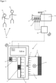
- a distance sensor 13 determines the distance to an object 14 (e.g. O 1 or O 2 ) in front of the camera or another device specifies a certain setting for the respective motor 11 or the respective motors ( Figure 1 ).
- object assignment 21 On the handwheel, the assignment of the object to a specific distance is called object assignment 21.
- the area directly adjacent to or surrounding the object assignment is called object assignment area 22 ( Figure 2 ). This can be defined in the settings on the control unit and/or the computer unit.
- the control element in this example the handwheel 4 ) adjusts itself and the user can steer beyond the specified position or make corrections to the movement of the control element itself; in the second case, the control element does not move of its own accord (the controlled motor 11 , however, does) and the user can add or subtract additional movements to the movement already carried out by the computer unit on the motor by moving the control element accordingly.
- the control element does not move of its own accord (the controlled motor 11 , however, does) and the user can add or subtract additional movements to the movement already carried out by the computer unit on the motor by moving the control element accordingly.
- Both cases are explained using the following example: In both cases, an actor 14 (e.g. O 1 ) who is approaching the camera is to be kept in focus.
- a distance sensor 13 continuously measures the distance of the actor 14 (e.g.
- the computer unit continuously adjusts the focus depending on the distance and moves the handwheel accordingly.
- the user still has the option of making corrections to the value specified by the computer unit by allowing himself to be guided by the moving handwheel, but can change the focus point depending on the situation by over- or under-controlling the handwheel rotation by applying additional positive or negative force.
- the computer unit The actor also follows the focus depending on the distance, but does not move the handwheel.
- the user now has the option of adding or subtracting an offset from the setting made by the computer unit with positive or negative rotations around the current point.
- the zero point i.e. the point at which the additional offset is zero
- Gestures can be understood as an evaluation of the impulse or force with which the user turns or stops the handwheel.
- it can be understood as the pressure on a possibly pressure-sensitive button.
- a sensor on the handwheel can also detect when the hand lets go of the handwheel.
- an object O 1 is being tracked in the supported execution mode and the tracking is to be switched to another object O 2
- the user can leave the first object assignment area by applying a defined additional force to the rotation of the handwheel and actively switch to the second object assignment area by rotating.
- the supported execution mode now focuses on the object O 2 to be tracked and from now on this object is tracked.
- an object change can also be carried out by selecting on a screen (e.g. touchscreen) 2 or 5 .
- the computer unit does not exert any force on the rotation of the handwheel as long as the object specified by the user is within the depth of field (in this area 23, all objects are in focus, even those at different distances). If there is a risk that the user will leave the depth of field 23 , the computer unit can ensure that this area is not accidentally left by applying an appropriate assisting force to the handwheel. Only when the user leaves the area with a sufficiently strong force does the computer unit switch off this assisting mode, which monitors the area boundaries. This mode can also be switched off only temporarily and switch on again as soon as a new object comes into the depth of field.
- the display 5 can either be permanently connected to the control unit 1 , while the display is updated sufficiently quickly and only the handwheel 4 rotates, or the handwheel and rotating display 5 are a unit and rotate together.
- the display on one of the screens can show a bird's eye view or a side view symbolically or superimposed on the current video image. This means that the boundaries of the focus zone are visible to the user, for example, and they can use them as a guide when operating the system. For better visualization, these areas can also be projected into the recording set using a laser or other optical projection mechanism.
- the aforementioned invention can be used in all areas of the film and broadcast sector.
- operating motion control applications e.g. swiveling camera heads, camera dollies, camera cranes, swiveling light control systems
- other areas of application In times of ever higher image resolution, this helps to focus precisely and accurately or to make work processes much faster. It can also be used to regulate the brightness of spotlights or similar. However, the invention can also be used in other areas of technology.
- a control unit 1 with a display 2 which has the following control elements: a handwheel 4 , a slider 7 and a joystick 8.
- a rotating display 5 is attached to the handwheel 4.
- a display 15 is also attached to the slider and a display 16 to the joystick (rocker).
- a reference point 3 which is fixedly attached to the control unit 1 , shows the current status of the motor 11 (for a movement axis of the lens 17 ) on the rotating display 5.
- a motor that can exert a force on a control element is shown as an example as motor 6 in the handwheel 4. This can also be present in the slider 7 or joystick 8.
- the control unit 1 is connected via a radio or cable connection 9 via a computer unit 10 to a motor 11 for driving an axis of a lens 17.
- the computer unit 10 can alternatively also be accommodated in the control unit 1 .
- a distance meter 13 attached to the camera 12 continuously measures the distance to objects 14 ( O 1 , O 2 )
- the reference point 3 is fixed to the control unit 1 , while the rotating display 5 in this variant can rotate with the handwheel 4.
- the reference point 3 shows the current setting for an object.
- the dashed lines 21 show object assignments, i.e. the assignment of a real object (in this case the actor "Michael” and the actress “Anna") to a symbol on the handwheel 4.
- a defined area around an object assignment 21 is called the object assignment area 22 of the object (the dark area of the name).
- the depth of field area 23 is grayed out and is located around the reference point 3 depending on the calculated depth of field.
- a graphic is used to show the effect of a force F specified by the computer unit 10 on the rotary movement as a function of the handwheel rotation position x .
- end stops are shown that define the outer limits of the entire adjustment range A and at which the counterforce on the handwheel 4 increases abruptly.
- Area B shows a "trough" where the force specified by the computer unit 10 on the handwheel increases the closer one gets to the extreme point x B (this can be the desired focus point on an object/object assignment point 21 )
- area C shows a "mountain” with the extreme point x C and thus the opposite case.
- Area D shows the supporting force that keeps the user in a certain area, e.g. depth of field, and protects against accidentally leaving the area at the limits.
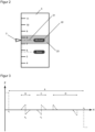
- a dynamic resistance R is shown as an example, which depends on the position x of the handwheel 4. At the outer limits x 1 and x 2 this increases steadily. In the intermediate area the changing resistance of a mechanical axis is shown, as it occurs in the case of location-dependent stiffness, determined by reading the motor current and can be converted by the computer unit 10 into corresponding forces on the handwheel 4 .
- FIG 5 A section of the rotating display 5 is shown.
- the reference point 3 is as in Figure 2 fixed to the control unit 1 , while the rotating display 5 in this variant can rotate with the handwheel 4.
- the dashed line 31 graphically shows the resistance of the mechanical movement axis depending on the position of the handwheel.
Landscapes
- Physics & Mathematics (AREA)
- General Physics & Mathematics (AREA)
- Engineering & Computer Science (AREA)
- General Engineering & Computer Science (AREA)
- Theoretical Computer Science (AREA)
- Human Computer Interaction (AREA)
- Mechanical Control Devices (AREA)
- User Interface Of Digital Computer (AREA)
Claims (17)
- Procédé pour commande ou réglage de moteurs des axes de déplacement des appareils du domaine du film et de la radiodiffusion,I. où une unité de commande (1), consistant au moins en un élément de commande (4 ; 7) asservit au moins un moteur (11) par radio ou connexion câblée à travers une unité informatique (10),II. l'unité de commande comportant un élément électromécanique (6),III. et dont l'élément de commande se présente soit sous forme d'un bouton de réglage manuel (4) ou d'un curseur (7),IV. et où l'élément électromécanique (6) est présent au moins dans cet élément de commande (4 ; 7) exerçant une force sur l'élément de commande soit dans son sens de mouvement positif ou négatif,V. qui génère un retour haptique à cet endroit,VI. pouvant modifier cette force de manière dynamique par des paramètres entrés ou lus à travers l'unité informatique, etVII. qui permet d'outrepasser manuellement cette force,VIII. et où les paramètres lus sont générés en fonction- de la position de l'objet à enregistrer par rapport à une caméra ou l'appareil à piloter, ou en fonction- du changement de la rigidité de ou de la charge appliquée sur une axe de déplacement de l'appareil à piloter, ou- d'un autre appareil qui détermine un certain réglage pour le moteur de la caméra ou de l'appareil à piloter,et traités par l'unité informatique.
- Procédé pour commande ou réglage de moteurs des axes de déplacement des appareils du domaine du film et de la radiodiffusion, oùi. où une unité de commande (1), consistant au moins en un élément de commande (4 ; 7) asservit au moins un moteur (11) par radio ou connexion câblée à travers une unité informatique (10),ii. l'unité de commande comportant un élément électromécanique (6),iii. et dont l'élément de commande se présente soit sous forme d'un bouton de réglage manuel (4) ou d'un curseur (7),iv. et où l'élément électromécanique est présent au moins dans cet élément de commande (4 ; 7) exerçant une force sur l'élément de commande soit dans son sens de mouvement positif ou négatif qui génère un retour haptique à cet endroit,v. modifiant cette force de manière dynamique par des paramètres entrés ou lus à travers l'unité informatique,vi. l'un des paramètres étant la rotation du bouton de réglage manuel ou le glissement du curseur par la main de l'utilisateur où l'impulsion ou la force avec laquelle l'utilisateur agit sur l'unité de commande est analysée,vii. ou bien où l'un des paramètres est l'entrée effectuée sur l'élément de commande faite par application d'une pression sur touche sensible à la pression ou par sélection sur écran (2 ; 5),viii. où l'unité informatique calcule par la suite une force dynamique qui tourne/déplace dans un sens et de manière autonome le bouton de réglage manuel/curseur pour atteindre une position déterminée ou pour agir avec une vitesse déterminée,ix. tout en permettant d'outrepasser cette force manuellement,
- Procédé selon revendication 1 ou 2,où la force exercée par l'élément électromécanique sur l'élément de commande est- à un moment ou une période donnés et/ou- en fonction de la position de l'élément de commande et/ou- en fonction de la position de l'objet à enregistrer- tellement faible ou absente, de façon à permettre l'opération de l'élément de commande sans trop de résistance, et permettant- à un autre moment ou une autre période et/ou- à une autre position de l'élément de commande et/ou- à une autre position d'un objet à enregistrerl'application d'une force dynamique réglable individuellement sur l'élément de commande.
- Procédé selon l'une des revendications 1 à 3,
où le retour haptique marque au moins une position de fin de course ou au moins une limitation d'une plage de rotation ou de glissement/de réglage. - Procédé selon l'une des revendications 1 à 4,
où le retour haptique permet la représentation d'un repérage ou d'un modèle de force ou bien la reproduction d'un comportement mécanique. - Procédé selon l'une des revendications 1 à 5,
où l'élément électromécanique exerce une force sur l'élément de commande pour que l'élément de commande se déplace de manière autonome à des points déterminés avec une vitesse déterminée tout en permettant à l'utilisateur d'intervenir à tout moment et d'outrepasser manuellement cette force en cas de besoin et sans commutation active. - Procédé selon l'une des revendications 1 à 6,
où un capteur de distance détecte au moins la position de l'objet à enregistrer. - Procédé selon revendication 1 à 7,
où un affichage monté sur l'unité ou l'élément de commande affiche et ajuste de manière dynamique la position d'au moins un objet à enregistrer, marquant éventuellement un des objets comme l'objet actif. - Procédé selon l'une des revendications 1 à 8,
permettant la sélection du suivi de certains objets à travers un écran tactile sur l'unité de commande ou sur l'élément de commande. - Procédé selon l'une des revendications 1 à 9,
où l'élément électromécanique exerce une force de suivi sur l'élément de commande uniquement lorsqu'un objet qui doit rester dans la zone de profondeur de champ ou dans une autre zone déterminée risque de sortir de celle-ci. - Procédé selon l'une des revendications 1 à 10,
où l'élément électromagnétique exerce une force de suivi sur l'élément de commande pour le suivi d'un objet, lorsque l'utilisateur introduit l'élément de commande dans une zone prédéfinie autour de l'objet en question. - Procédé selon l'une des revendications 1 à 11,
où la partie de l'affichage visible des éléments de commande conçus comme bouton de réglage manuel avec affichage sur toute la circonférence et une plage de réglage nécessitant plusieurs tours est toujours mise à jour à la zone actuelle. - Procédé selon l'une des revendications 1 à 12,
où des informations basées sur les paramètres entrés ou lus en fonction de l'objet d'enregistrement ou de la modification d'état d'un objet ou d'un appareil, sont projetées dans le plateau d'enregistrement sans que ces informations projetées interfèrent avec l'image enregistrée. - Dispositif pour commande ou réglage de moteurs des axes de déplacement des appareils du domaine du film et de la radiodiffusion,consistant en une unité informatique (10) et une unité de commande (1) comportant un élément électromécanique (6),l'unité de commande (1) étant équipée au moins d'un élément de commande (4 ; 7) et reliée au moins indirectement par radio ou connexion câblée (9) via l'unité de calcul (10) à au moins un moteur (11).dont l'élément de commande se présente soit sous forme d'un bouton de réglage manuel (4) ou d'un curseur (7), et où l'élément électromécanique (6) est présent au moins dans cet élément de commande (4 ; 7) de l'unité de commande (1) exerçant une force sur l'élément de commande soit dans son sens de mouvement positif ou négatif, qui génère un retour haptique à cet endroit,et où l'unité de commande (1) est conçue de façon à pouvoir modifier cette force par des paramètres entrés ou lus à travers l'unité informatique (10),et où l'élément de commande (4 ; 7) est conçu de façon à pouvoir outrepasser manuellement cette force au niveau de l'élément de commande,et où l'unité informatique (10) est conçue de façon à permettre la génération de paramètres lus en fonction- de la position de l'objet à enregistrer (14) par rapport à une caméra ou l'appareil à piloter, ou en fonction- du changement de la rigidité de ou de la charge appliquée sur une axe de déplacement de l'appareil à piloter, ou- d'un autre appareil qui détermine un certain réglage pour le moteur de la caméra ou de l'appareil à piloter,et traités par l'unité informatique
- Dispositif pour commande ou réglage de moteurs des axes de déplacement des appareils du domaine du film et de la radiodiffusion,consistant en une unité informatique (10) et une unité de commande (1) comportant un élément électromécanique (6),l'unité de commande (1) étant équipée au moins d'un élément de commande (4 ; 7) et reliée au moins indirectement par radio ou connexion câblée (9) via l'unité de calcul (10) à au moins un moteur (11).dont l'élément de commande se présente soit sous forme d'un bouton de réglage manuel (4) ou d'un curseur (7), et où l'élément électromécanique (6) est présent au moins dans cet élément de commande (4 ; 7) de l'unité de commande (1) exerçant une force sur l'élément de commande soit dans son sens de mouvement positif ou négatif, qui génère un retour haptique à cet endroit,et où l'unité de commande (1) est conçue de façon à pouvoir modifier cette force à travers l'unité informatique (10),- l'un des paramètres étant la rotation du bouton de réglage manuel ou le glissement du curseur par la main de l'utilisateur où l'impulsion ou la force avec laquelle l'utilisateur agit sur l'unité de commande est analysée,- ou bien où l'un des paramètres est l'entrée effectuée sur l'élément de commande faite par application d'une pression sur touche sensible à la pression ou par sélection sur écran (2 ; 5),- où l'unité informatique est configurée pour calculer par la suite une force dynamique qui tourne/déplace le bouton de réglage manuel/curseur dans un sens et de manière autonome pour atteindre une position déterminée ou pour agir avec une vitesse déterminée, et- où l'élément de commande (4 ; 7) est conçu de façon à pouvoir outrepasser manuellement cette force au niveau de l'élément de commande (4 ; 7),
- Dispositif selon revendication 14 ou 15,
où au moins un des éléments de commande (4 ; 7) est le bouton de réglage manuel (4) avec affichage sur toute sa circonférence (5). - Dispositif selon l'une des revendications 14 à 16,
où l'unité informatique (10) peut calculer à partir des valeurs obtenues par le capteur de distance (13) au moins un des paramètres entrés ou lus et générer avec celui-ci un signal statique ou dynamique par radio ou connexion câblée (9) pour commander l'élément électromécanique (6) qui génère la force pour le retour haptique sur l'élément de commande (4 ; 7).
Applications Claiming Priority (2)
| Application Number | Priority Date | Filing Date | Title |
|---|---|---|---|
| DE102019003510.0A DE102019003510B4 (de) | 2019-05-20 | 2019-05-20 | Verfahren und Vorrichtung zur Steuerung von Motoren im Film- und Broadcastbereich |
| PCT/EP2020/062943 WO2020234011A1 (fr) | 2019-05-20 | 2020-05-08 | Procédé et dispositif de commande de moteurs dans le secteur du film et de la radiodiffusion |
Publications (3)
| Publication Number | Publication Date |
|---|---|
| EP3973354A1 EP3973354A1 (fr) | 2022-03-30 |
| EP3973354C0 EP3973354C0 (fr) | 2024-10-23 |
| EP3973354B1 true EP3973354B1 (fr) | 2024-10-23 |
Family
ID=70740582
Family Applications (1)
| Application Number | Title | Priority Date | Filing Date |
|---|---|---|---|
| EP20726322.9A Active EP3973354B1 (fr) | 2019-05-20 | 2020-05-08 | Procédé et dispositif de commande de moteurs dans le secteur du film et de la radiodiffusion |
Country Status (4)
| Country | Link |
|---|---|
| US (1) | US11899343B2 (fr) |
| EP (1) | EP3973354B1 (fr) |
| DE (1) | DE102019003510B4 (fr) |
| WO (1) | WO2020234011A1 (fr) |
Families Citing this family (2)
| Publication number | Priority date | Publication date | Assignee | Title |
|---|---|---|---|---|
| WO2022087828A1 (fr) * | 2020-10-27 | 2022-05-05 | 深圳市大疆创新科技有限公司 | Procédé de commande de roue de suivi de mise au point, roue de suivi de mise au point et support de stockage |
| DE102022108642A1 (de) * | 2022-04-08 | 2023-10-12 | TRUMPF Hüttinger GmbH + Co. KG | Plasmazünderkennungsvorrichtung zum Anschluss an eine Impedanzanpassungsschaltung für ein Plasmaerzeugungssystem |
Citations (4)
| Publication number | Priority date | Publication date | Assignee | Title |
|---|---|---|---|---|
| EP2706407A2 (fr) | 2012-09-06 | 2014-03-12 | Arnold & Richter Cine Technik GmbH & Co. Betriebs KG | Unité de télécommande pour objectif et caméra |
| WO2015025222A2 (fr) | 2013-08-23 | 2015-02-26 | Raytheon Canada Limited | Dispositif de commande de sensation tactile |
| WO2016049781A1 (fr) | 2014-10-03 | 2016-04-07 | Andra Motion Technologies Inc. | Système et techniques de capture d'images |
| US20160248969A1 (en) | 2015-02-24 | 2016-08-25 | Redrock Microsystems, Llc | Lidar assisted focusing device |
Family Cites Families (14)
| Publication number | Priority date | Publication date | Assignee | Title |
|---|---|---|---|---|
| US5059019A (en) | 1990-05-21 | 1991-10-22 | Mccullough Greg R | Laser framefinder |
| US5889670A (en) | 1991-10-24 | 1999-03-30 | Immersion Corporation | Method and apparatus for tactilely responsive user interface |
| DE19712049A1 (de) | 1997-03-21 | 1998-09-24 | Mannesmann Vdo Ag | Bedienvorrichtung |
| DE19926597A1 (de) | 1999-06-11 | 2000-12-14 | Bosch Gmbh Robert | Bedienvorrichtung |
| JP4061105B2 (ja) | 2002-03-29 | 2008-03-12 | アルプス電気株式会社 | 力覚付与装置 |
| US7283120B2 (en) * | 2004-01-16 | 2007-10-16 | Immersion Corporation | Method and apparatus for providing haptic feedback having a position-based component and a predetermined time-based component |
| DE102004015947A1 (de) * | 2004-03-25 | 2005-10-13 | Arnold & Richter Cine Technik Gmbh & Co Betriebs Kg | Verfahren und Vorrichtung zum Einstellen der Bildschärfe am Kameraobjektiv einer Laufbildkamera |
| US8174512B2 (en) | 2006-06-02 | 2012-05-08 | Immersion Corporation | Hybrid haptic device utilizing mechanical and programmable haptic effects |
| US7658349B2 (en) | 2006-10-26 | 2010-02-09 | Honeywell International Inc. | Pilot flight control stick haptic feedback system and method |
| DE202009014504U1 (de) | 2009-10-27 | 2010-02-04 | Longmore, Martin | Steuerungsvorrichtung für ein Objektiv einer Kamera |
| DE102015110633A1 (de) | 2015-07-01 | 2017-01-05 | Inventus Engineering Gmbh | Haptische Bedieneinrichtung und Verfahren |
| DE102011121021B4 (de) | 2011-12-13 | 2022-12-01 | Arnold & Richter Cine Technik Gmbh & Co. Betriebs Kg | Bedieneinheit |
| US9609200B2 (en) * | 2014-09-24 | 2017-03-28 | Panavision International, L.P. | Distance measurement device for motion picture camera focus applications |
| DE102016118460A1 (de) | 2016-09-29 | 2018-03-29 | Jungheinrich Aktiengesellschaft | Flurförderzeug mit einem Bedienhebel sowie Verfahren zur Bedienung eines solchen Flurförderzeugs |
-
2019
- 2019-05-20 DE DE102019003510.0A patent/DE102019003510B4/de active Active
-
2020
- 2020-05-08 WO PCT/EP2020/062943 patent/WO2020234011A1/fr not_active Ceased
- 2020-05-08 EP EP20726322.9A patent/EP3973354B1/fr active Active
- 2020-05-08 US US17/612,771 patent/US11899343B2/en active Active
Patent Citations (4)
| Publication number | Priority date | Publication date | Assignee | Title |
|---|---|---|---|---|
| EP2706407A2 (fr) | 2012-09-06 | 2014-03-12 | Arnold & Richter Cine Technik GmbH & Co. Betriebs KG | Unité de télécommande pour objectif et caméra |
| WO2015025222A2 (fr) | 2013-08-23 | 2015-02-26 | Raytheon Canada Limited | Dispositif de commande de sensation tactile |
| WO2016049781A1 (fr) | 2014-10-03 | 2016-04-07 | Andra Motion Technologies Inc. | Système et techniques de capture d'images |
| US20160248969A1 (en) | 2015-02-24 | 2016-08-25 | Redrock Microsystems, Llc | Lidar assisted focusing device |
Also Published As
| Publication number | Publication date |
|---|---|
| US20220244622A1 (en) | 2022-08-04 |
| EP3973354C0 (fr) | 2024-10-23 |
| DE102019003510A1 (de) | 2020-11-26 |
| DE102019003510B4 (de) | 2023-02-23 |
| EP3973354A1 (fr) | 2022-03-30 |
| WO2020234011A1 (fr) | 2020-11-26 |
| US11899343B2 (en) | 2024-02-13 |
Similar Documents
| Publication | Publication Date | Title |
|---|---|---|
| DE102013004692B4 (de) | 3D-Eingabegerät mit einem zusätzlichen Drehregler | |
| EP1958436A1 (fr) | Procede et dispositif permettant de deplacer une camera placee sur une tete panoramique / inclinable le long d'une trajectoire de deplacement predefinie | |
| EP1930923B1 (fr) | Dispositif de commutation pour appareils médicaux ou chirurgicaux | |
| DE102004008714A1 (de) | Objektivsteuersystem und Fokusinformations-Anzeigevorrichtung | |
| DE102018009025A1 (de) | Robotersteuervorrichtung zum Einstellen eines Bewegungskoordinatensystems | |
| DE102012112268A1 (de) | Knöpfe mit dynamisch projizierten Symbolen | |
| EP3534210B1 (fr) | Unité d'affichage à réglage du foyer | |
| EP3973354B1 (fr) | Procédé et dispositif de commande de moteurs dans le secteur du film et de la radiodiffusion | |
| DE102015004745B4 (de) | Verfahren zum Betreiben eines Kraftfahrzeugs und zugehöriges Kraftfahrzeug | |
| WO2018049447A1 (fr) | Dispositif de commande et procédé de commande pour machines industrielles à entraînement de déplacement commandé | |
| EP2706407A2 (fr) | Unité de télécommande pour objectif et caméra | |
| EP2822814A1 (fr) | Véhicule à moteur équipé d'un rétroviseur électronique | |
| EP3688549A1 (fr) | Équipement commutateur | |
| EP3985964A1 (fr) | Dispositif de télécommande pour une caméra à image animée | |
| EP3343311B1 (fr) | Levier de commande pourvu d'unité de rétroaction active | |
| EP3204813A1 (fr) | Microscope avec diaphragme à iris à adaptation automatique | |
| EP2920657B1 (fr) | Appareil de commande pour une machine-outil affectant des instructions de commande, en fonction d'une position, à des axes de déplacement individuels de la machine-outil | |
| DE102008009973A1 (de) | Verfahren zum Führen eines medizinischen Gerätes | |
| DE19856722A1 (de) | Bedienvorrichtung mit einer Handhabe mit mindestens zwei Verstellfreiheitsgraden | |
| WO2019011373A1 (fr) | Levier de commande muni d'un guide à coulisse | |
| DE102005012051B4 (de) | Bedienhebel für eine Bedieneinrichtung eines Personenbeförderungsmittels | |
| EP1213188A2 (fr) | Dispositif de commande | |
| WO2000077721A1 (fr) | Dispositif de commande | |
| DE102019106683B4 (de) | Verfahren und System zum Herstellen eines Kontaktes zwischen einer Nutzerhand und einem Bedienelement einer Vorrichtung | |
| DE102016004630A1 (de) | Werkzeugmaschine sowie Verwendung eines berührempfindlichen Displays zur Ansteuerung eines Maschinenteils einer Werkzeugmaschine |
Legal Events
| Date | Code | Title | Description |
|---|---|---|---|
| STAA | Information on the status of an ep patent application or granted ep patent |
Free format text: STATUS: UNKNOWN |
|
| STAA | Information on the status of an ep patent application or granted ep patent |
Free format text: STATUS: THE INTERNATIONAL PUBLICATION HAS BEEN MADE |
|
| PUAI | Public reference made under article 153(3) epc to a published international application that has entered the european phase |
Free format text: ORIGINAL CODE: 0009012 |
|
| STAA | Information on the status of an ep patent application or granted ep patent |
Free format text: STATUS: REQUEST FOR EXAMINATION WAS MADE |
|
| 17P | Request for examination filed |
Effective date: 20211122 |
|
| AK | Designated contracting states |
Kind code of ref document: A1 Designated state(s): AL AT BE BG CH CY CZ DE DK EE ES FI FR GB GR HR HU IE IS IT LI LT LU LV MC MK MT NL NO PL PT RO RS SE SI SK SM TR |
|
| DAV | Request for validation of the european patent (deleted) | ||
| DAX | Request for extension of the european patent (deleted) | ||
| STAA | Information on the status of an ep patent application or granted ep patent |
Free format text: STATUS: EXAMINATION IS IN PROGRESS |
|
| 17Q | First examination report despatched |
Effective date: 20231220 |
|
| GRAP | Despatch of communication of intention to grant a patent |
Free format text: ORIGINAL CODE: EPIDOSNIGR1 |
|
| STAA | Information on the status of an ep patent application or granted ep patent |
Free format text: STATUS: GRANT OF PATENT IS INTENDED |
|
| INTG | Intention to grant announced |
Effective date: 20240612 |
|
| GRAS | Grant fee paid |
Free format text: ORIGINAL CODE: EPIDOSNIGR3 |
|
| GRAA | (expected) grant |
Free format text: ORIGINAL CODE: 0009210 |
|
| STAA | Information on the status of an ep patent application or granted ep patent |
Free format text: STATUS: THE PATENT HAS BEEN GRANTED |
|
| AK | Designated contracting states |
Kind code of ref document: B1 Designated state(s): AL AT BE BG CH CY CZ DE DK EE ES FI FR GB GR HR HU IE IS IT LI LT LU LV MC MK MT NL NO PL PT RO RS SE SI SK SM TR |
|
| REG | Reference to a national code |
Ref country code: GB Ref legal event code: FG4D Free format text: NOT ENGLISH |
|
| REG | Reference to a national code |
Ref country code: CH Ref legal event code: EP |
|
| REG | Reference to a national code |
Ref country code: DE Ref legal event code: R096 Ref document number: 502020009562 Country of ref document: DE |
|
| REG | Reference to a national code |
Ref country code: IE Ref legal event code: FG4D Free format text: LANGUAGE OF EP DOCUMENT: GERMAN |
|
| U01 | Request for unitary effect filed |
Effective date: 20241122 |
|
| U07 | Unitary effect registered |
Designated state(s): AT BE BG DE DK EE FI FR IT LT LU LV MT NL PT RO SE SI Effective date: 20241204 |
|
| PG25 | Lapsed in a contracting state [announced via postgrant information from national office to epo] |
Ref country code: IS Free format text: LAPSE BECAUSE OF FAILURE TO SUBMIT A TRANSLATION OF THE DESCRIPTION OR TO PAY THE FEE WITHIN THE PRESCRIBED TIME-LIMIT Effective date: 20250223 Ref country code: HR Free format text: LAPSE BECAUSE OF FAILURE TO SUBMIT A TRANSLATION OF THE DESCRIPTION OR TO PAY THE FEE WITHIN THE PRESCRIBED TIME-LIMIT Effective date: 20241023 |
|
| PG25 | Lapsed in a contracting state [announced via postgrant information from national office to epo] |
Ref country code: ES Free format text: LAPSE BECAUSE OF FAILURE TO SUBMIT A TRANSLATION OF THE DESCRIPTION OR TO PAY THE FEE WITHIN THE PRESCRIBED TIME-LIMIT Effective date: 20241023 |
|
| PG25 | Lapsed in a contracting state [announced via postgrant information from national office to epo] |
Ref country code: NO Free format text: LAPSE BECAUSE OF FAILURE TO SUBMIT A TRANSLATION OF THE DESCRIPTION OR TO PAY THE FEE WITHIN THE PRESCRIBED TIME-LIMIT Effective date: 20250123 |
|
| PG25 | Lapsed in a contracting state [announced via postgrant information from national office to epo] |
Ref country code: GR Free format text: LAPSE BECAUSE OF FAILURE TO SUBMIT A TRANSLATION OF THE DESCRIPTION OR TO PAY THE FEE WITHIN THE PRESCRIBED TIME-LIMIT Effective date: 20250124 |
|
| PG25 | Lapsed in a contracting state [announced via postgrant information from national office to epo] |
Ref country code: PL Free format text: LAPSE BECAUSE OF FAILURE TO SUBMIT A TRANSLATION OF THE DESCRIPTION OR TO PAY THE FEE WITHIN THE PRESCRIBED TIME-LIMIT Effective date: 20241023 |
|
| PGFP | Annual fee paid to national office [announced via postgrant information from national office to epo] |
Ref country code: GB Payment date: 20250323 Year of fee payment: 6 |
|
| PG25 | Lapsed in a contracting state [announced via postgrant information from national office to epo] |
Ref country code: RS Free format text: LAPSE BECAUSE OF FAILURE TO SUBMIT A TRANSLATION OF THE DESCRIPTION OR TO PAY THE FEE WITHIN THE PRESCRIBED TIME-LIMIT Effective date: 20250123 |
|
| U20 | Renewal fee for the european patent with unitary effect paid |
Year of fee payment: 6 Effective date: 20250325 |
|
| PG25 | Lapsed in a contracting state [announced via postgrant information from national office to epo] |
Ref country code: SM Free format text: LAPSE BECAUSE OF FAILURE TO SUBMIT A TRANSLATION OF THE DESCRIPTION OR TO PAY THE FEE WITHIN THE PRESCRIBED TIME-LIMIT Effective date: 20241023 |
|
| PG25 | Lapsed in a contracting state [announced via postgrant information from national office to epo] |
Ref country code: SK Free format text: LAPSE BECAUSE OF FAILURE TO SUBMIT A TRANSLATION OF THE DESCRIPTION OR TO PAY THE FEE WITHIN THE PRESCRIBED TIME-LIMIT Effective date: 20241023 |
|
| PLBI | Opposition filed |
Free format text: ORIGINAL CODE: 0009260 |
|
| PG25 | Lapsed in a contracting state [announced via postgrant information from national office to epo] |
Ref country code: CZ Free format text: LAPSE BECAUSE OF FAILURE TO SUBMIT A TRANSLATION OF THE DESCRIPTION OR TO PAY THE FEE WITHIN THE PRESCRIBED TIME-LIMIT Effective date: 20241023 |
|
| PLAX | Notice of opposition and request to file observation + time limit sent |
Free format text: ORIGINAL CODE: EPIDOSNOBS2 |
|
| 26 | Opposition filed |
Opponent name: ARNOLD & RICHTER CINE TECHNIK GMBH & CO.BETRIEBS KG Effective date: 20250723 |
|
| PLBB | Reply of patent proprietor to notice(s) of opposition received |
Free format text: ORIGINAL CODE: EPIDOSNOBS3 |
|
| REG | Reference to a national code |
Ref country code: CH Ref legal event code: H13 Free format text: ST27 STATUS EVENT CODE: U-0-0-H10-H13 (AS PROVIDED BY THE NATIONAL OFFICE) Effective date: 20251223 |
|
| U1N | Appointed representative for the unitary patent procedure changed after the registration of the unitary effect |
Representative=s name: EISENFUEHR SPEISER; DE |
|
| PG25 | Lapsed in a contracting state [announced via postgrant information from national office to epo] |
Ref country code: CH Free format text: LAPSE BECAUSE OF NON-PAYMENT OF DUE FEES Effective date: 20250531 |