EP3973346B1 - Augenverfolgungmodul und am kopf tragbare vorrichtung - Google Patents
Augenverfolgungmodul und am kopf tragbare vorrichtung Download PDFInfo
- Publication number
- EP3973346B1 EP3973346B1 EP20706689.5A EP20706689A EP3973346B1 EP 3973346 B1 EP3973346 B1 EP 3973346B1 EP 20706689 A EP20706689 A EP 20706689A EP 3973346 B1 EP3973346 B1 EP 3973346B1
- Authority
- EP
- European Patent Office
- Prior art keywords
- camera
- eye
- module
- electric connector
- head
- Prior art date
- Legal status (The legal status is an assumption and is not a legal conclusion. Google has not performed a legal analysis and makes no representation as to the accuracy of the status listed.)
- Active
Links
Images

Classifications
-
- G—PHYSICS
- G02—OPTICS
- G02B—OPTICAL ELEMENTS, SYSTEMS OR APPARATUS
- G02B27/00—Optical systems or apparatus not provided for by any of the groups G02B1/00 - G02B26/00, G02B30/00
- G02B27/0093—Optical systems or apparatus not provided for by any of the groups G02B1/00 - G02B26/00, G02B30/00 with means for monitoring data relating to the user, e.g. head-tracking, eye-tracking
-
- G—PHYSICS
- G02—OPTICS
- G02B—OPTICAL ELEMENTS, SYSTEMS OR APPARATUS
- G02B27/00—Optical systems or apparatus not provided for by any of the groups G02B1/00 - G02B26/00, G02B30/00
- G02B27/01—Head-up displays
- G02B27/0179—Display position adjusting means not related to the information to be displayed
-
- G—PHYSICS
- G02—OPTICS
- G02B—OPTICAL ELEMENTS, SYSTEMS OR APPARATUS
- G02B27/00—Optical systems or apparatus not provided for by any of the groups G02B1/00 - G02B26/00, G02B30/00
- G02B27/01—Head-up displays
- G02B27/017—Head mounted
- G02B27/0176—Head mounted characterised by mechanical features
-
- G—PHYSICS
- G06—COMPUTING OR CALCULATING; COUNTING
- G06F—ELECTRIC DIGITAL DATA PROCESSING
- G06F3/00—Input arrangements for transferring data to be processed into a form capable of being handled by the computer; Output arrangements for transferring data from processing unit to output unit, e.g. interface arrangements
- G06F3/01—Input arrangements or combined input and output arrangements for interaction between user and computer
- G06F3/011—Arrangements for interaction with the human body, e.g. for user immersion in virtual reality
- G06F3/013—Eye tracking input arrangements
-
- H—ELECTRICITY
- H04—ELECTRIC COMMUNICATION TECHNIQUE
- H04N—PICTORIAL COMMUNICATION, e.g. TELEVISION
- H04N23/00—Cameras or camera modules comprising electronic image sensors; Control thereof
- H04N23/90—Arrangement of cameras or camera modules, e.g. multiple cameras in TV studios or sports stadiums
-
- G—PHYSICS
- G02—OPTICS
- G02B—OPTICAL ELEMENTS, SYSTEMS OR APPARATUS
- G02B27/00—Optical systems or apparatus not provided for by any of the groups G02B1/00 - G02B26/00, G02B30/00
- G02B27/01—Head-up displays
- G02B27/0149—Head-up displays characterised by mechanical features
- G02B2027/0154—Head-up displays characterised by mechanical features with movable elements
- G02B2027/0158—Head-up displays characterised by mechanical features with movable elements with adjustable nose pad
-
- G—PHYSICS
- G02—OPTICS
- G02B—OPTICAL ELEMENTS, SYSTEMS OR APPARATUS
- G02B27/00—Optical systems or apparatus not provided for by any of the groups G02B1/00 - G02B26/00, G02B30/00
- G02B27/01—Head-up displays
- G02B27/017—Head mounted
- G02B2027/0178—Eyeglass type
-
- G—PHYSICS
- G02—OPTICS
- G02B—OPTICAL ELEMENTS, SYSTEMS OR APPARATUS
- G02B27/00—Optical systems or apparatus not provided for by any of the groups G02B1/00 - G02B26/00, G02B30/00
- G02B27/01—Head-up displays
- G02B27/0179—Display position adjusting means not related to the information to be displayed
- G02B2027/0187—Display position adjusting means not related to the information to be displayed slaved to motion of at least a part of the body of the user, e.g. head, eye
Definitions
- Embodiments of the present invention relate to eye tracking modules and head-wearable devices that may be used for eye tracking and/or to detect one or more gaze-related parameters of a user, as e.g. described in document WO 2018/064141 .
- Portable eye tracking devices for example in the form of head-wearable spectacle-like systems offer many advantages over stationary, remote eye tracking systems when it comes to the range of possible application scenarios and use cases.
- Outdoor activities like sports or tasks like operating large machinery are examples for eye tracking application areas in which free head and body movement is required and for which head-worn devices are thus the solution of choice.
- use cases often also require the wearer to wear specialized eyewear, like protective eyeglasses of various kinds.
- Pilot visor helmets, skiing- or swimming-goggles, sports helmets, head-band structures and welding protective googles are further examples.
- physiological features like head or nose shapes of the wearers can vary in wide ranges, e.g. as a function of ethnicity or age.
- these portable devices traditionally provide integrated spectacle-type systems which do not provide enough flexibility to fit different specialized scenarios and/or are not suitable for children.
- the eye tracking module includes a module housing which is, at least in a lower portion, at least substantially mirror symmetric with respect to a central plane and shaped to partly surround a nose of the user.
- a scene camera is arranged in and/or on the module housing.
- the eye tracking module further includes at least one of a first eye camera arranged in and/or on the lower portion of the module housing, and a second eye camera arranged in and/or on the lower portion of the module housing.
- a first distance between the first eye camera and the central plane is at most about 20 mm.
- a second distance between the second eye camera and the central plane at least substantially corresponds to the first distance and/or is at most about 20 mm.
- the eye tracking module includes a module housing which is, at least in a lower portion, at least substantially mirror symmetric with respect to a central plane and shaped to partly surround a nose of the user.
- a scene camera is arranged in and/or on the module housing.
- At least one of a first eye camera and a second eye camera is arranged in and/or on the lower portion of the module housing.
- the eye tracking module further includes an electric connector arranged in and/or on the module housing. The electric connector is in electric connection with at least one of the scene camera, the first eye camera and the second eye camera.
- the head-wearable device includes a frame having a central portion which is, when the head-wearable device is worn by a user, arranged next to, typically closest to a nose of the user, and a first electric connector arranged in and/or on the central portion.
- inventions include systems and sets including one or more head-wearable devices and an eye tracking module as described herein for complementing the one or more head-wearable devices.
- an eye tracking module includes a module housing which is, at least in a lower portion, shaped to partly surround a nose of the user, in particular a nasal bridge of the user's nose, and at least substantially mirror symmetric with respect to a (virtual) central plane of at least the lower portion, i.e. the lower portion or even the complete module housing are at least substantially mirror symmetric with respect to the central plane.
- a scene camera is arranged in and/or on the module housing.
- a first eye camera and/or a second eye camera are arranged in and/or on the lower portion of the module housing.
- a first distance between the first eye camera and the central plane is at most about 20 mm.
- a second distance between the second eye camera and the central plane at least substantially corresponds to the first distance and/or is at most about 20 mm.
- the term "at least substantially mirror symmetric with respect to a plane" as used within specification intends to describe that at least the outer shells or boundaries of two elements or objects are mirror symmetric with respect to the plane with an accuracy which is typically achievable with the materials and manufacturing methods used, in particular with an accuracy of at least 5 % or even at least 2 % or 1%, at least on average, and/or that two (virtual) parts of an outer shell or boundary of one element or object are mirror symmetric with respect to the plane with an accuracy of at least 5% or even at least 2 % or 1%, at least on average.
- a centre of gravity of the outer shells lies within the plane or is at most about 1 mm or even at most about 0.5 mm, more typically at most about 0.2 mm spaced apart from the plane.
- a second distance at least substantially corresponds to the first distance intends to describe that a relative difference between the first distance and the second distance is at most about 5%, more typically at most about 2 % or even 1%, and/or that an absolute difference between the first distance and the second distance is at most about 1 mm, more typically at most about 0.5 mm or even 0.2 mm.
- the eye tracking module may be used for attachably complementing and/or completing head-wearable devices configured for being wearable on a user's head, in particular head-wearable devices as described herein.
- At least one of the first distance and the second distance may be at most about 15 mm, at most about 14 mm, or even at most about 12 mm.
- At least one of the first distance and the second distance may be at least about 2 mm or even at least about 5 mm.
- the eye tracking module both has a first eye camera for taking first images of at least a portion of a first eye of the user, e.g. a left eye, of the user, and a second eye camera for taking second images of at least a portion of a second eye of the user, e.g. of a right eye of the user.
- first and second eye cameras are also referred to as left eye camera and right eye camera, and as left camera and right camera, respectively.
- first camera first eye camera
- second camera second eye camera
- right camera are used synonymously herein.
- the eye tracking module typically comprises a left camera and a right eye camera, wherein the left camera serves for taking a left image or a stream of images of at least a portion of the left eye of the user, and wherein the right camera takes an image or a stream of images of at least a portion of a right eye of the user.
- the left eye camera and the right eye camera are arranged at least substantially mirror-symmetric with respect to the central plane.
- the recorded eye images do not necessarily need to be a picture as visible by the human eye, but can also be an appropriate representation of the recorded (filmed) eye in a range of light non-visible for humans.
- the recorded eye images may e.g. be used for determining one or more gaze-related parameters of a user wearing a head-wearable device provided with the eye tracking module. However, this is typically done by an external device, e.g. a companion device.
- an external device e.g. a companion device.
- the gaze-direction related parameter may be a gaze direction, a cyclopean gaze direction, a 3D gaze point, a 2D gaze point, a visual axis orientation, an optical axis orientation, a pupil axis orientation, and a line of sight orientation of the user.
- the gaze-related parameter may be a gaze-direction related parameter or a position and/or an eyelid closure, a pupil area, a pupil size, a pupil diameter, a measure of cognitive load, a sclera characteristic, an iris diameter, a characteristic of a blood vessel, a cornea characteristic of at least one eye, a cornea radius, an eyeball radius, a distance pupil-center to cornea-center, a distance cornea-center to eyeball-center, a distance pupil-center to limbus center, a cornea keratometric index of refraction, a cornea index of refraction, a vitreous humor index of refraction, a distance crystalline lens to eyeball-center, to cornea center and/or to corneal apex, a crystalline lens index of refraction, a degree of astigmatism, an orientation angle of a flat and/or a steep axis, a limbus major and/or minor axes orientation, an eye cyclo-torsion, an eye intra-
- the scene camera may be used for taking images of a field of view of the user wearing the head-wearable device provided with the eye tracking module.
- the images of the field of view of the user are also referred to as scene images.
- the scene camera hence must not be understood as a camera for taking a picture of an eye of the user.
- the eye tracking module also includes a scene camera, it is in the following also referred to as (add-on) camera module.
- Corresponding scene and eye images may e.g. be used to determine what the user is looking at. Again, this is typically done by the external device.
- Points and directions may be specified within the scene camera images, an eye camera coordinate system, a scene camera coordinate system, an eye tracking module coordinate system, a head coordinate system, a world coordinate system and/or any other suitable coordinate system.
- the tracking module may be comparatively compact.
- the central plane is also referred to as vertical plane and middle plane, respectively.
- the field of view of wearer may not be occluded, at least not discernible for the wearer.
- an obstruction of the visible field of the user may essentially not be noticeable by the user since the human mind mostly ignores any obstruction in the nose area of the face, because the nose itself forms a permanent obstruction of the optical field.
- the tracking module may easily be adapted to different wearers and use cases/scenarios.
- the scene camera is typically centrally arranged, i.e. at least close to the central plane and/ or close to (expected) eye midpoint of the user.
- the latter also facilitates a compact design.
- the influence of parallax error for gaze prediction may be reduces this way significantly.
- At least one of a maximum extension of the module housing and a maximum extension of the lower portion of the module housing may be at most about 4 cm, more typically at most about 3 cm or even 2.5 cm.
- At least one of a further maximum extension of the module housing and a further maximum extension of the lower portion of the module housing is at most about 4 cm, more typically at most about 3 cm or even 2.5 cm.
- the module housing or even the eye tracking module may fit into an enveloping cuboid with dimensions of at most about 3 cm ⁇ 5 cm ⁇ 5 cm or even at most about 2 cm ⁇ 4 cm ⁇ 4.5 cm.
- the module housing further includes an upper portion which may or may not be substantially mirror symmetric with respect to the central plane.
- the scene camera is typically arranged in and/or on the upper portion of the module housing.
- the scene camera may comprise an optical axis which is at least substantially arranged in the central plane (to reduce parallax error). Gaze estimation error due to parallax is minimized by placing the scene camera as close as possible to the eye or midpoint of the eyes.
- the lower portion typically includes a first (left) leg portion and a second (right) leg portion which are at least substantially mirror-symmetric with respect to the central plane.
- the eye tracking module typically further includes an electric connector arranged in and/or on the module housing, typically in and/or on the upper portion, and in electric connection with at least one of the scene camera, the first eye camera and the second eye camera, typically with all of the cameras of the eye tracking module.
- the camera(s) of the eye tracking module may be provided with electric power through the electric connector (via an internal wiring).
- additional space inside the module housing for energy storage may not be required.
- the eye tracking module typically includes a module housing which is, at least in a lower portion, at least substantially mirror symmetric with respect to a central plane and shaped to partly surround a nose of the user, a scene camera arranged in and/or on the module housing, at least one of a first eye camera arranged in and/or on the lower portion of the module housing, and a second eye camera arranged in and/or on the lower portion of the module housing, and an electric connector arranged in and/or on the module housing, and in electric connection with at least one of the scene camera, the first eye camera and the second eye camera.
- a first distance between the first eye camera and the central plane is typically at most about 20 mm
- a second distance between the second eye camera and the central plane typically at least substantially corresponds to the first distance, and/or is at most about 20 mm.
- the electric connector By means of the electric connector, a simple (standardized/standardizable) connection between the eye tracking module and head-wearable device may be provided. This leave lots of design freedom for the frames of the head-wearable device it is supposed to be used with. Furthermore, the (generic) eye tracking module which includes all or at least most of the expensive electronics can be produces in large numbers, since it fits all use cases, thereby reducing cost-per-piece, while the frames of the head-wearable devices with no special electronics which are cheaper to manufacture to begin with can be produced in fewer numbers (which is usually more expensive), thus reducing overall manufacturing costs.
- the electric connector is typically arranged in the central plane, for example at least substantially mirror-symmetric with respect to the central plane. This may also contribute to a compact design of the eye tracking module.
- the electric connector may be either arranged on the same side of the module as the scene camera and/or facing in the same general direction as the scene camera or opposite thereto.
- module designs may be provided which allow the module to be connected to head-wearable devices from the wearer side.
- This may be advantageous in case the general construction of the head-wearable device is such that it covers a larger portion of the facial area comprising the eyes because of some functional requirement (e.g. displays, screens, shielding in front of the eyes/face) of the head-wearable, such as in AR/VR goggles, diving googles, welding goggles or other protective googles.
- module designs may be provided which allow the module to be connected to head-wearable devices from the side facing away from the wearer. This may be advantageous in case the general construction of the head-wearable device prohibits any modifications of the wearer-facing side (e.g. because a hermetic seal around the eyes is provided by the head-wearable, or the head-wearable comprises electrodes that need to be in contact with the wearer's face).
- the electric connector may be arranged on a top surface of the module. Accordingly, module designs may be provided which allow the module to be connected to head-wearable devices which do not comprise any structures which extend into the nose region of the face of the wearer when worn on the head, such as for example different helmets or head-band structures.
- the electric connector is typically arranged between the first eye camera and the second eye camera, and/or between the scene camera and at least one of the first eye camera and the second eye camera, at least in a projection onto a plane perpendicular to the optical axis of the scene camera and/or in a projection onto the central plane or a plane parallel to the central plane.
- the electric connector may be implemented as a plug or a socket and typically fits with a corresponding electric connector of the head-wearable device.
- the electric connector may be an electro-mechanical connector and/or may include one or more snap fit elements, magnets or the like. Alternatively or in addition, the electric connector may include on or more screws or threaded holes for respective screws.
- Providing the module with the electric connector enables the module to be constructed comparatively compact, without the need for an internal power supply, while at the same time encapsulating the necessary camera hardware in an optimal way and preserving flexibility as to the compatibility of the module with use case specific head-wearable devices.
- the module housing may also include a mechanical connector (separate to or integrated into the electro-mechanical connector) which is adapted to cooperate with a corresponding counterpart of the head-wearable device, and selected from the list of a magnetic connector, a screw connection, a snap fit connection, a friction fit, a bayonet coupling, and a velcro-based connector.
- a mechanical connector separate to or integrated into the electro-mechanical connector
- the mechanical connector may also be based on a connection principle for establishing a permanent, non-releasable connection, such as via gluing, welding or friction welding.
- the electric connector may also be used for data exchange (through the head-wearable device).
- At least one of the scene camera and the electric connector is arranged in the central plane.
- At least one of the scene camera and the electric connector is, in a projection onto a plane perpendicular to the central plane arranged between the first eye camera and the second eye camera.
- the electric connector is, in the projection onto a plane perpendicular to the optical axis of the scene camera, typically arranged between the scene camera and at least one of the first eye camera and the second eye camera.
- the scene camera can, in the projection onto a plane perpendicular to the optical axis of the scene camera, be arranged between the electric connector and at least one of the first eye camera and the second eye camera.
- the eye tracking module typically further includes a first nose pad attached to the lower portion, in particular the first leg portion, and/or a second nose pad attached to the lower portion, in particular the second leg portion.
- the first nose pad and/or the second nose pad may be adjustable and/or exchangeable attached to the lower portion and the respective leg portion, respectively.
- first eye camera may be arranged on and/or in the first leg portion and/or the second eye camera may be arranged on and/or in the second leg portion.
- At least one of a first angle between an optical axis of the first eye camera and the central plane, and a second angle between an optical axis of the second eye camera and the central plane is in a range from about 150° to 142° (or -30° to about -38°), more typically about 144° (or -36°), i.e. 144°+/- 1° (or -36°+/- 1°). Accordingly, an optimal view of the eye cameras onto an eyeball of the user is enabled.
- the first angle may at least substantially correspond to the second angle, i.e. with an accuracy of at least about 1° or even 0.5°.
- the head-wearable device comprises not more than two wearer-side facing eye cameras (one for each eye of the user) and one front-side facing scene camera.
- the eye tracking module may further include a first light source arranged next to the first eye camera and/or a second light source arranged next to the second eye camera for illuminating the left eye and right eye of the user, for example a respective IR-LED.
- the first light source may be arranged in and/or on the first leg portion.
- the second light source may be arranged in and/or on in the second leg portion
- the module housing may include or even be made of two shells. Accordingly manufacturing may be facilitated.
- the module housing and/or the two shells may include or may be made of a metal, in particular a light metal such as aluminium or magnesium and/or a plastics. Accordingly a particularly lightweight eye tracking module may be provided.
- the module housing may be made by Al- or Mg- pressure casting or die casting.
- the module housing may be made out of a plastics, for example by injection moulding.
- the module housing may be at least substantially watertight and/or rigid.
- the latter may result in particularly precise and/or constant camera poses (after manufacturing and optional adaptation to the user). This is advantageous for achieving high eye tracking accuracy.
- the eye tracking module typically further includes a controller in electric connection with at least one of the electric connector, the scene camera, the first eye camera and the second eye camera, more typically with the electric connector and all cameras.
- the controller is typically arranged within in the module housing, more typically enclosed by the module housing.
- the controller may be configured for at least one of:
- the scene camera may be fixedly integrated into the housing or detachably connectable to the module housing. The same may apply to the eye camera(s).
- the scene camera may have a resolution of at least 640 ⁇ 480 pixels or at least 800 ⁇ 600 pixels, more typically of at least 1024 ⁇ 768 pixels, and even more typically of at least 1280 ⁇ 1024 pixels or at least 1920 ⁇ 1080 pixels (at least VGA SVGA or HD).
- the resolution of the left and right images may be comparatively low.
- the pixel number of the left images and of the typically equally sized right images may be at most 40000, particularly at most 10000, particularly at most 5000, and more particularly at most 2500 or even 1000.
- a head-wearable device includes a frame having a central portion which is, when the head-wearable device is worn by a user, arranged next to a nose of the user, and a first electric connector arranged in and/or on the central portion.
- the frame of the head-wearable device is typically configured such that the head-wearable device can be worn on a head of a user, for example in a way usual glasses are worn.
- the frame and head-wearable device, respectively, complemented with the eye tracking module as described herein, more particular the eye tracking module of the complemented head-wearable device when worn by the user may be supported at least partially by a nose area of the user's face.
- the head-wearable device may be a spectacle device, a pilot visor helmet, an AR head-wearable display, a VR head-wearable display or a goggles, for example a skiing-goggles, a swimming-goggles, a sports helmet, a head-band structure or a welding protective googles.
- the frame may include a first frame portion at least partly surrounding a first ocular opening, a second frame portion at least partly surrounding a second ocular opening, and the central portion may form (or be formed by) a bridge portion mechanically connecting the first frame portion and the second frame portion
- the head-wearable device may include a frame including a first frame portion at least partly surrounding a first ocular opening, a second frame portion at least partly surrounding a second ocular opening, a bridge portion mechanically connecting the first frame. portion and the second frame portion, and a first electric connector arranged on and/or in the bridge portion.
- the frame of the head-wearable device may include a passage opening for receiving a protruding portion of the scene camera of the eye tracking module as explained herein.
- the head-wearable device typically includes a second electric connector arranged in and/or on the frame of the head-wearable device, and an internal wiring electrically connecting the first electric connector and the second electric connector (for power supply and/or data exchange).
- the second electric connector may be used for power supply from and/or data exchange with a companion computing device.
- the second electric connector may be a USB-connector such as an USB-C-connector.
- the second electric connector may also be a connector for another external computer bus, in particular a computer bus and power connector such as a Thunderbolt-connector (Thunderbolt 3 uses USB-C connectors) or a Lightning connector (typically supporting the USB-protocol) or even an Ethernet-connector (Power over Ethernet).
- Thunderbolt-connector Thunderbolt 3 uses USB-C connectors
- Lightning connector typically supporting the USB-protocol
- Ethernet-connector Power over Ethernet
- the second electric connector is typically arranged at a dorsal end of the frame of the head-wearable device and/or of a temple of the head-wearable device. Thereby a connection can be established in an unobtrusive way and wearing comfort is increased.
- the eye tracking module may be connected with a (mobile) computing companion device such as smartphone, a tablet or the like, supplied with electric power from the companion device and even controlled by the companion device, for example by an app running on the companion device.
- a (mobile) computing companion device such as smartphone, a tablet or the like
- the companion device may be used for analysing the images of the cameras.
- the companion device may be used for eye tracking and computing a sequence of gaze-direction related parameter(s) of the user, respectively, based on the camera images.
- the controller of the module may itself be adapted for determining a gaze-related parameter of the user.
- neither the eye tracking module nor the head-wearable device may have an internal energy storage such as a battery. Accordingly, the eye tracking module and the head-wearable (spectacles) device may be particularly lightweight. Further, less heat may be produced during device operation compared to a device with an internal (rechargeable) energy storage. This may also improve comfort of wearing.
- a system or set includes one or more head-wearable devices, and an eye tracking module as explained herein.
- the system or set may include different types of a head-wearable devices each of which is exchangeably complementable with the eye tracking module.
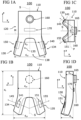
- an embodiment of an eye tracking module 100 for attaching to a head-wearable devices of a user is explained.
- a module housing 110 of module 100 may be mirror symmetric with respect to a virtual central plane S. Further, a lower portion 130 of housing 110 may have a left leg portion 134 and a right portion leg portion 135 formed such that a recess 138 for a user's nose is formed in lower portion 130.
- module housing 110 accommodates in an upper portion 120 a scene camera 160 and an electric connector 170, and, in the lower portion 130, a left eye camera 140 and a right eye camera 150.
- the left leg portion 134 accommodates the left eye camera 140
- the right leg portion 135 accommodates the right eye camera 150.
- the left eye camera 140 and the right eye camera 150 are arranged mirror symmetric to each other with respect to central plane S. Further, both the scene camera 160 and the electric connector 170 are arranged in and mirror symmetric with respect to central plane S.
- the electric connector 170 is arranged between scene camera 160 and the eye cameras 140, 150.
- FIG. 1A eye cameras 140, 150 are indicated as slightly protruding from the housing 110, however they can be embodied completely integrated into the housing, with no protruding parts.
- a first distance between the (first) left eye camera 140 and the central plane S is typically at most 20 mm, at least in front view and in the projection onto the plane P, respectively.
- a second distance between the (second) right eye camera 150 and the central plane S is typically at most 20 mm, at least in front view and in the projection onto the plane P, respectively.
- the eye cameras 140, 150 are mirror-symmetric with respect to central plane S. Accordingly, the first distance matches the second distance.
- the first and second distances may be respective minimum distances (each d y1 /2 in the exemplary embodiment) or more typically respective maximum distances (each d y2 /2 in the exemplary embodiment).
- Said first and second distances may also measure the respective distance between an (optical) center of the eye camera 140, 150 and the central plane S, in the direction perpendicular to plane S. Further, said camera centers may for example be half-way between d y1 /2 and d y2 /2.
- electric connector 170 and scene camera 160 may overlap with each other and/or be spaced apart from the eye cameras 140, 150.
- a first angle ⁇ 1 between and an optical axis 145 of left eye camera 140 and central plane S, and a second angle ⁇ 2 between an optical axis 155 of right eye camera 150 and central plane S may be in a range from about 150° to 142° (or -30° to about -38°).
- first angle ⁇ 1 may corresponds to the second angle ⁇ 2 , at least within an accuracy of 1° or even less.
- the total height d z of module housing 110 (extension of modular housing 110 in a direction perpendicular to plane M, z-direction) may be in a range from about 2.5 cm to about 5 cm, more typically in a range from about 3 cm to about 4.5 cm.
- the widths of modular housing 110 typically varies as function of the height (z) and is typically in a range from about 2 cm to 5 cm, more typically in a range from about 2 cm to about 4 cm.
- the width dy 4 of upper portion 120 may be substantially constant and/or lower than the maximum width dy 3 of lower portion 130, for example by a factor of 1.1 to 1.4.
- legs 134, 135 are typically bent.
- the depth d x1 (extension in direction of optical axis 165 of scene camera 160, which in the example shown is parallel to the x-direction) of module housing 110 may vary as function of height.
- the depth d x1 may be in a range from about 1 cm to about 2 cm, more typically in a range from about 1 cm to 1.7 cm.
- the total extension d x in x-direction may be in a range from about 1.2 cm to about 3 cm, more typically in a range from about 1.5 cm to 2 cm.
- the scene camera 160 may protrude from module housing 110.
- the scene camera 160 and/or the electric connector 170 may also be arranged within module housing 110, i.e. such that they are accessible from the outside but do not protrude from the housing.
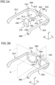
- Fig. 2A illustrates a perspective view of a head-wearable device 500 and eye tracking module 100 to be mounted to head-wearable device 500.
- head-wearable device 500 is implemented as spectacles device. Accordingly, frame 510 of spectacles device 500 has a front portion 512 only partly surrounding a left ocular opening 511 and a right ocular opening 521. A bridge portion 503 of front portion 512 is arranged between the ocular openings 511, 521. Further, a left temple 513 and a right temple 523 are attached to front portion 512.
- bridge portion 503 includes a recess or opening 515 for receiving module housing 110 of module 100.
- the recess or opening 515 is formed such that upper portion 120 of module housing 110 fits into it.
- sidewalls of upper portion 120 and frame 510 in the bridge portion 503 may include respective interfitting structures such as a groove and a projection extending in x-direction.
- a first electric connector 570 fitting with the electric connector 170 (hidden in Fig. 2A ) of module 100 is accommodated in bridge portion 503 and arranged on the wearer-side of bridge portion 503.
- a passage opening 560 for scene camera 160 and the field of view (FOV) of scene camera 160, respectively, is formed in bridge portion 503.
- a second electric connector 580 in electric contact with the first electric connector 570 (via a not shown internal wiring) is accommodated at the dorsal and of right temple 523.
- Electric connector 523 may be used for connecting with a companion device such as a smart phone or tablet.
- electric connector 523 may be a USB-connector.
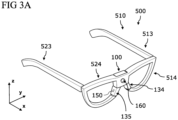
- Figures 2B , 3A illustrate respective perspective views of the head-wearable device 500 including the attached eye tracking module 100.
- central plane S of module 100 may, in mounted state, also represent a symmetry plane for frame 510.
- leg portions 134, 135 of module 100 may at least substantially complement frame 510 below bridge portion 503 so that the ocular openings 512, 521 are at least substantially surrounded by material of frame 510 and module housing 110.
- connection structures between lower ends of legs 134, 135 and free ends of frame 510 in the ocular regions are not shown in figures 2B , 3A .
- Fig. 4A and Fig. 4B illustrate respective perspective views of a head-wearable device 600 and an eye tracking module 200.
- Head-wearable device 600 and eye tracking module 200 are similar to head-wearable device 500 and eye tracking module 100 explained above with regard to figures 1A to 3A .
- module housing 210 of eye tracking module 200 is also shaped as a "nose-bridge"-like element for attachment to a typically at least substantially complementary frame structure in a (central) bridge portion 603 of a frame 610 of head-wearable device 600, in particular a recess or opening 615 of bridge portion 603.
- recess or opening 615 including the electric connector 670 is formed at the front side of front portion 612 of frame 610. Accordingly, the electric connector (hidden in Fig. 4A ) of module 200 is arranged at the backside of upper portion 220 of module housing 210, and thus opposite to the scene camera 260.
- passage opening for the scene camera 260 through bridge portion 603 of the frame 610 may not be provided.
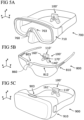
- Fig. 5A-C illustrate perspective views of further head-wearables devices 700 to 900 and another eye tracking module 100' for attachably complementing head-wearable devices 700, 800, 900.
- eye tracking module 100' is similar to eye tracking module 100 explained above with regard to Fig. 1A to Fig. 2B .
- the electric connector 170' and the scene camera 160' of eye tracking module 100' may also be arranged on a frontside of a module housing 110'. Accordingly, module 100' is suitable for attaching to a wearer-side of the respective central or bridge portion 703, 803, 903 of head-wearables 700 - 900.
- Fig. 5A and Fig. 5C show head-wearables 700, 900 which better lend themselves to a wearer-side connection of the module 100', namely a diving goggles 700 and a VR-type head-wearable device 900, respectively.
- Internal wiring and a cooperating connector on the head-wearables 700 - 900 serve as power supply for module 100' and data interface to and from module 100', as in the previously described embodiments.
- module 100' is shown without scene camera in this variant.
- the scene camera of module 100' can either be removable, or it can be provided in a manner such that it does not protrude from the housing 110'. In both cases a lid 161' may be provided to close the corresponding opening in the module housing 110'. Alternatively, modules without scene camera can be provided for this use case.
- a camera module comprises a module body comprising an upper portion and a lower portion, in particular a module housing comprising respective portions.
- the upper portion comprises an electric connector for connecting with a corresponding connector of a head-wearable device of a user. , and a scene camera in electric contact with the electric connector.
- the lower portion is at least substantially mirror symmetric with respect to a central plane, and shaped to partly surround a nose of the user.
- the camera module further comprises at least two of: a scene camera accommodated in the upper portion, and in electric contact with the electric connector; a left eye camera accommodated in the lower portion, and in electric contact with the electric connector; and a right eye camera accommodated in the lower portion, and in electric contact with the electric connector.
Landscapes
- Physics & Mathematics (AREA)
- Engineering & Computer Science (AREA)
- General Physics & Mathematics (AREA)
- Optics & Photonics (AREA)
- General Engineering & Computer Science (AREA)
- Theoretical Computer Science (AREA)
- Human Computer Interaction (AREA)
- Multimedia (AREA)
- Signal Processing (AREA)
Claims (15)
- Ein Augenverfolgungsmodul (100, 100', 200) zur anbringbaren Ergänzung einer am Kopf zu tragenden Vorrichtung (500 - 900) eines Benutzers in einem Stück, wobei das Modul (100, 100', 200) umfasst:- ein Modulgehäuse (110, 110', 210), das zumindest in einem unteren Abschnitt (130, 230) zumindest im Wesentlichen spiegelsymmetrisch in Bezug auf eine zentrale Ebene (S) ist und so geformt ist, dass es teilweise eine Nase des Benutzers umgeben kann;- eine im und/oder am Modulgehäuse (110, 110', 120) angeordnete Szenenkamera (160, 260);- mindestens eine erste Augenkamera (140, 240), die in und/oder an dem unteren Abschnitt (130, 230) des Modulgehäuses (110, 110', 210) angeordnet ist, und eine zweite Augenkamera (150, 250), die in und/oder an dem unteren Abschnitt (130, 230) des Modulgehäuses (110, 110', 210) angeordnet ist; und- einen elektrischen Anschluss (170, 270), der in und/oder an dem Modulgehäuse (110, 110', 120) angeordnet ist und mit mindestens einer der Szenenkamera (160, 260), der ersten Augenkamera (140, 240) und der zweiten Augenkamera (150, 250) in elektrischer Verbindung steht.
- Modul (100, 100', 200) nach Anspruch 1 , wobei ein erster Abstand zwischen der ersten Augenkamera (140, 240) und der Mittelebene (S) höchstens etwa 20 mm beträgt, wobei ein zweiter Abstand (d/2) zwischen der zweiten Augenkamera (150, 250) und der Mittelebene (S) zumindest im Wesentlichen dem ersten Abstand entspricht, und/oder wobei der zweite Abstand höchstens etwa 20 mm beträgt, wobei der elektrische Anschluss (170, 270) auf einer Oberseite des Moduls angeordnet ist, wobei der elektrische Anschluss (170, 270) in der Mittelebene (S) angeordnet ist, wobei der elektrische Anschluss (170, 270) zwischen der ersten Augenkamera (140, 240) und der zweiten Augenkamera (150, 250) und/oder zwischen der Szenekamera (160, 260) und mindestens einer der ersten Augenkamera (140, 240) und der zweiten Augenkamera (150, 250) angeordnet ist, wobei der elektrische Anschluss (170, 270) als ein Stecker oder eine Buchse ausgeführt ist, wobei der elektrische Anschluss (170, 270) ein elektromechanischer Anschluss ist, wobei der elektrische Anschluss (170, 270) zu einem entsprechenden elektrischen Anschluss der am Kopf zu tragenden Vorrichtung passt, und/oder wobei der elektrische Anschluss (170, 270) auf der gleichen Seite des Moduls angeordnet ist und/oder in die gleiche allgemeine Richtung wie die Szenenkamera (160, 260) oder gegenüberliegend zu dieser weist,und/oder wobei der elektrische Anschluss (170, 270) in elektrischer Verbindung mit der Szenenkamera (160, 260), der ersten Augenkamera (140, 240) und der zweiten Augenkamera (150, 250) steht.
- Modul (100, 100', 200) nach einem der vorhergehenden Ansprüche, wobei mindestens einer der ersten und zweiten Abstände höchstens etwa 15 mm, höchstens etwa 14 mm oder sogar höchstens etwa 12 mm beträgt, wobei mindestens einer der ersten und zweiten Abstände mindestens etwa 2 mm oder sogar mindestens etwa 5 mm beträgt, und/oder wobei die erste Augenkamera (140, 240) und die zweite Augenkamera (150, 250) zumindest im Wesentlichen spiegelsymmetrisch in Bezug auf die Mittelebene (S) angeordnet sind.
- Modul (100, 100', 200) nach einem der vorhergehenden Ansprüche, wobei die Szenenkamera (160, 260) eine optische Achse (165, 265) aufweist, die zumindest im Wesentlichen in der Mittelebene (S) angeordnet ist.
- Modul (100, 100', 200) nach einem der vorhergehenden Ansprüche, wobei das Modulgehäuse (110, 110', 210) einen oberen Abschnitt (120, 220) aufweist, wobei der obere Abschnitt (120, 220) im Wesentlichen spiegelsymmetrisch zur Mittelebene (S) ist, wobei der untere Abschnitt (120, 220) einen ersten Schenkelabschnitt (134, 234) und einen zweiten Schenkelabschnitt (135, 235) aufweist, die zumindest im Wesentlichen spiegelsymmetrisch zur Mittelebene (S) sind, wobei die erste Augenkamera (140, 240) an und/oder in dem ersten Schenkelabschnitt (134, 234) angeordnet ist, wobei die zweite Augenkamera (150, 250) an und/oder in dem zweiten Schenkelabschnitt (135, 235) angeordnet ist, wobei ein erstes Nasenpolster an dem ersten Schenkelabschnitt (134, 234) angebracht ist, wobei ein zweites Nasenpolster an dem zweiten Schenkelabschnitt (135, 235) angebracht ist, und/oder wobei mindestens eines von dem ersten Nasenpolster und dem zweiten Nasenpolster verstellbar und/oder austauschbar an dem jeweiligen Schenkelabschnitt angebracht ist.
- Modul (100, 100', 200) nach einem der vorhergehenden Ansprüche, wobei die Szenenkamera (160, 260) fest in das Gehäuse (110, 110', 210) integriert oder mit dem Modulgehäuse (110, 110', 210) lösbar verbindbar ist, wobei die Szenenkamera (160, 260) im oberen Teil (120, 220) des Modulgehäuses (110, 110', 210) angeordnet ist, wobei die Szenenkamera (160, 260) und/oder der elektrische Anschluss (170, 270) in der Mittelebene (S) angeordnet ist, wobei die Szenenkamera (160, 260) und/oder der elektrische Anschluss (170, 270) in einer Projektion auf eine Ebene (P, M) senkrecht zur Mittelebene (S) zwischen der ersten Augenkamera (140, 240) und der zweiten Augenkamera (150, 250) angeordnet ist, und/oder wobei der elektrische Anschluss (170, 270) in der Projektion auf eine Ebene (P) senkrecht zur optischen Achse (165, 265) der Szenekamera (160, 260) zwischen der Szenekamera (160, 260) und mindestens einer der ersten Augenkamera (140, 240) und der zweiten Augenkamera (150, 250) angeordnet ist.
- Modul (100, 100', 200) nach einem der vorhergehenden Ansprüche, wobei mindestens ein erster Winkel (γ1) zwischen einer optischen Achse (145) der ersten Augenkamera (140) und der zentralen Ebene (S), und einem zweiten Winkel (γ2) zwischen einer optischen Achse (155) der zweiten Augenkamera (150) und der Mittelebene (S) in einem Bereich von etwa 150° bis 142° (oder -30° bis etwa -38°), typischerweise etwa 144° (oder -36°) liegt, und/oder wobei der erste Winkel (γ1) zumindest im Wesentlichen dem zweiten Winkel (γ2) entspricht.
- Modul (100, 100', 200) nach einem der vorhergehenden Ansprüche, wobei das Modulgehäuse (110, 110', 210) zwei Schalen aufweist, wobei das Modulgehäuse (110, 110', 210) und/oder die beiden Schalen aus einem Metall oder einem Kunststoff bestehen, wobei das Modulgehäuse (110, 110', 210) aus den beiden Schalen hergestellt ist, wobei das Modulgehäuse (110, 110', 210) zumindest im Wesentlichen starr ist, und/oder wobei das Modulgehäuse (110, 110', 210) wasserdicht ist.
- Modul (100, 100', 200) nach einem der vorhergehenden Ansprüche, ferner umfassend mindestens eines von:- eine erste Lichtquelle, die neben der ersten Augenkamera (140, 240) angeordnet ist; und- eine zweite Lichtquelle, die neben der zweiten Augenkamera (150, 250) angeordnet ist.
- Modul (100, 100', 200) nach einem der vorhergehenden Ansprüche, wobei das Modulgehäuse (110, 110', 210) eine Steuerungseinheit umfasst, die in elektrischer Verbindung mit mindestens einem der folgenden Elemente steht: dem elektrischen Anschluss (170, 270), der Szenenkamera (160, 260), der ersten Augenkamera (140, 240) und der zweiten Augenkamera (150, 250)wobei die Steuerungseinheit typischerweise für mindestens einen der folgenden Schritte konfiguriert ist:- Empfangen von Steuerbefehlen über den elektrischen Anschluss (170, 270);- Auslösen einer jeweiligen Bild- oder Videoaufzeichnung der Szenenkamera (160, 260), der ersten Augenkamera (140, 240) und/oder der zweiten Augenkamera (150, 250);- Verteilen von Energie an oder zwischen Kameras und/oder Lichtquellen;- Vorverarbeiten eines Szenenbildes, das von der Szenenkamera (160, 260) empfangen wird, eines ersten Augenbildes, das von der ersten Augenkamera (140, 240) empfangen wird, und/oder eines zweiten Augenbildes, das von der zweiten Augenkamera (140, 240) empfangen wird;- Komprimieren eines Szenenbildes, eines ersten Augenbildes und/oder eines zweiten Augenbildes;- Bestimmen eines blickbezogenen Parameters basierend auf einem ersten und/oder zweiten Augenbild;- Bilden eines Datensatzes, der das Szenenbild, das erste Augenbild, das zweite Augenbild, das vorverarbeitete Szenenbild, das vorverarbeitete erste Augenbild, das vorverarbeitete zweite Augenbild und/oder einen Zeitstempel umfasst; und- Senden des Datensatzes an den elektrischen Anschluss (170, 270), insbesondere als Netzwerkpakete und/oder als USB-Pakete.
- Modul (100, 100', 200) nach einem der vorangehenden Ansprüche, wobei das Modulgehäuse (110, 110', 210) einen mechanischen Anschluss umfasst, der dazu geeignet ist, mit einem entsprechenden Gegenstück der am Kopf zu tragenden Vorrichtung zusammenzuwirken, und der ausgewählt ist aus der Liste: ein magnetischer Anschluss, eine Schraubverbindung, eine Schnappverbindung, eine Reibungspassung, ein auf einem Klettverschluss basierender Anschluss und ein Verbindungsprinzip zum Herstellen einer dauerhaften, nicht lösbaren Verbindung, wie beispielsweise durch Kleben, Schweißen oder Reibschweißen.
- Eine am Kopf zu tragende Vorrichtung (500 - 900), die geeignet ist, mit dem Augenverfolgungsmodul (100, 100', 200) nach einem der vorhergehenden Ansprüche verbunden zu werden, wobei die am Kopf zu tragende Vorrichtung (500 - 900) umfasst:- einen Rahmen (510 - 910) mit einem zentralen Abschnitt (503, 603, 703, 803, 903), der, wenn die am Kopf zu tragende Vorrichtung (500 - 900) von einem Benutzer getragen wird, am nächsten zu einer Nase des Benutzers angeordnet ist; und- einen ersten elektrischen Anschluss (570, 670), der in und/oder an dem zentralen Abschnitt (503, 603, 703, 803, 903) angeordnet ist.
- Die am Kopf zu tragende Vorrichtung (500, 600) nach Anspruch 12, wobei der Rahmen (510, 610) umfasst:- einen ersten Rahmenabschnitt (514, 614), der zumindest teilweise eine erste Augenöffnung (511, 611) umgibt;- einen zweiten Rahmenabschnitt (524, 624), der eine zweite Augenöffnung (521, 621) zumindest teilweise umgibt, undwobei der zentrale Abschnitt (503, 603) einen Brückenabschnitt (503, 603) bildet, der den ersten Rahmenabschnitt (514, 614) und den zweiten Rahmenabschnitt (524, 624) mechanisch verbindet.
- Die am Kopf zu tragende Vorrichtung (500 - 900) nach Anspruch 12 oder 13, wobei die am Kopf zu tragende Vorrichtung (500 - 900) eine Brillenvorrichtung, ein Pilotenvisier, ein Helm oder eine Brille, eine Skibrille, eine Schwimmbrille, ein Sporthelm, eine Kopfbandstruktur oder eine Schweißerschutzbrille ist, wobei der erste elektrische Anschluss (570, 670) ein elektromechanischer Anschluss ist, wobei der erste elektrische Anschluss (570, 670) an einer dem Benutzer zugewandten Seite des zentralen Abschnitts (503, 603, 703, 803, 903) oder gegenüberliegend dazu angeordnet ist, und/oder wobei die am Kopf zu tragende Vorrichtung (500 - 900) außerdem mindestens eines der folgenden Elemente umfasst:- eine Ausnehmung oder Öffnung zur Aufnahme eines oberen Abschnitts des Modulgehäuses (110, 110', 210) nach einem der Ansprüche 1 bis 21;- eine Durchgangsöffnung (560) zur Aufnahme eines vorstehenden Teils der Szenenkamera (160) des Moduls (100, 100', 200) nach einem der vorhergehenden Ansprüche;- einen zweiten elektrischen Stecker (580), wobei der zweite elektrische Stecker (580) typischerweise ein USB-Stecker ist und/oder an einem dorsalen Ende des Rahmens (510, 610) und/oder eines Bügels (523) der am Kopf tragbaren Vorrichtung (500, 600) angeordnet ist; und- eine interne Verdrahtung, die den ersten elektrischen Anschluss (570) und den zweiten elektrischen Anschluss (580) zur Stromversorgung und/oder zum Datenaustausch elektrisch verbindet.
- Ein System, das Folgendes umfasst:- die am Kopf zu tragende Vorrichtung (500 - 900) nach einem der Ansprüche 12 bis 14; und- das Augenverfolgungsmodul (100, 100', 200) nach einem der Ansprüche 1 bis 11.
Applications Claiming Priority (1)
| Application Number | Priority Date | Filing Date | Title |
|---|---|---|---|
| PCT/EP2020/054386 WO2021164867A1 (en) | 2020-02-19 | 2020-02-19 | Eye tracking module and head-wearable device |
Publications (3)
| Publication Number | Publication Date |
|---|---|
| EP3973346A1 EP3973346A1 (de) | 2022-03-30 |
| EP3973346B1 true EP3973346B1 (de) | 2024-12-25 |
| EP3973346C0 EP3973346C0 (de) | 2024-12-25 |
Family
ID=69650602
Family Applications (1)
| Application Number | Title | Priority Date | Filing Date |
|---|---|---|---|
| EP20706689.5A Active EP3973346B1 (de) | 2020-02-19 | 2020-02-19 | Augenverfolgungmodul und am kopf tragbare vorrichtung |
Country Status (3)
| Country | Link |
|---|---|
| US (1) | US12140771B2 (de) |
| EP (1) | EP3973346B1 (de) |
| WO (1) | WO2021164867A1 (de) |
Families Citing this family (9)
| Publication number | Priority date | Publication date | Assignee | Title |
|---|---|---|---|---|
| EP3973346B1 (de) * | 2020-02-19 | 2024-12-25 | Pupil Labs GmbH | Augenverfolgungmodul und am kopf tragbare vorrichtung |
| EP4281829B1 (de) * | 2020-12-21 | 2024-09-11 | Viewpointsystem GmbH | Augenverfolgungskit für brillen |
| US12498776B2 (en) * | 2021-05-05 | 2025-12-16 | Raghunand Bhagwan | Quick battery recharge system for wearable electronic devices |
| US12468164B2 (en) | 2021-09-09 | 2025-11-11 | Viewpointsystem Gmbh | Nose pad eye/gaze tracking module applicable to smart glasses |
| CN119365809A (zh) * | 2022-06-30 | 2025-01-24 | 苹果公司 | 眼睛跟踪系统 |
| EP4303652B1 (de) * | 2022-07-07 | 2025-08-20 | Pupil Labs GmbH | Kameramodul, am kopf tragbare augenverfolgungsvorrichtung und verfahren zur herstellung eines kameramoduls |
| US12501175B2 (en) | 2022-07-07 | 2025-12-16 | Pupil Labs Gmbh | Camera module, head-wearable eye tracking device, and method for manufacturing a camera module |
| EP4361704A1 (de) | 2022-10-27 | 2024-05-01 | Pupil Labs GmbH | Augenverfolgungsmodul und am kopf tragbare vorrichtung |
| WO2024237753A1 (ko) * | 2023-05-12 | 2024-11-21 | 삼성전자주식회사 | 시선 및 얼굴을 추적하는 웨어러블 전자 장치 |
Citations (7)
| Publication number | Priority date | Publication date | Assignee | Title |
|---|---|---|---|---|
| US20040059212A1 (en) | 2002-04-22 | 2004-03-25 | Abreu Marcio Marc | Apparatus and method for measuring biologic parameters |
| WO2008045137A1 (en) | 2006-05-03 | 2008-04-17 | E-Vision, Llc | Spectacle frame bridge housing electronics for electro-active spectacle lenses |
| US20140055747A1 (en) | 2011-03-18 | 2014-02-27 | Walter Nistico | Optical Measuring Device and Method for Capturing at Least One Parameter of at Least One Eye Wherein an Illumination Characteristic is Adjustable |
| WO2014048199A1 (zh) | 2012-09-28 | 2014-04-03 | Yu Yongbo | 眼镜测配装置、眼镜测配服务端和眼镜测配方法 |
| US20160206196A1 (en) | 2013-08-23 | 2016-07-21 | Ernst Pfleger | Spectacles and method for determining the pupil center of both of the wearer's eyes |
| US20180092592A1 (en) * | 2015-06-14 | 2018-04-05 | Facense Ltd. | Detecting an allergic reaction from nasal temperatures |
| US20190235237A1 (en) | 2018-02-01 | 2019-08-01 | Beijing 7Invensun Technology Co., Ltd. | Device Adapted To Eyeglasses |
Family Cites Families (185)
| Publication number | Priority date | Publication date | Assignee | Title |
|---|---|---|---|---|
| US4852988A (en) | 1988-09-12 | 1989-08-01 | Applied Science Laboratories | Visor and camera providing a parallax-free field-of-view image for a head-mounted eye movement measurement system |
| US6351273B1 (en) | 1997-04-30 | 2002-02-26 | Jerome H. Lemelson | System and methods for controlling automatic scrolling of information on a display or screen |
| WO1999005988A2 (en) | 1997-07-30 | 1999-02-11 | Applied Science Laboratories | An eye tracker using an off-axis, ring illumination source |
| EP1027627B1 (de) | 1997-10-30 | 2009-02-11 | MYVU Corporation | Schnittstellensystem für brillen |
| EP1032872A1 (de) | 1997-11-17 | 2000-09-06 | BRITISH TELECOMMUNICATIONS public limited company | Benutzerschnittstelle |
| DE19807902A1 (de) | 1998-02-25 | 1999-09-09 | Genesys Elektronik Gmbh | Verfahren und Einrichtung zur Ermittlung der Gleichgewichtskontrolle eines Lebewesens |
| ES2401132T3 (es) | 2000-10-07 | 2013-04-17 | Metaio Gmbh | Dispositivo y procedimiento para la determinación de la orientación de un ojo |
| US6771423B2 (en) | 2001-05-07 | 2004-08-03 | Richard Geist | Head-mounted virtual display apparatus with a near-eye light deflecting element in the peripheral field of view |
| US6943754B2 (en) | 2002-09-27 | 2005-09-13 | The Boeing Company | Gaze tracking system, eye-tracking assembly and an associated method of calibration |
| US7306337B2 (en) | 2003-03-06 | 2007-12-11 | Rensselaer Polytechnic Institute | Calibration-free gaze tracking under natural head movement |
| US20060240005A1 (en) | 2003-07-24 | 2006-10-26 | Universita Degli Studi Di Perugia | Methods and compositions for increasing the efficiency of therapeutic antibodies using alloreactive natural killer cells |
| US6889412B2 (en) | 2003-08-12 | 2005-05-10 | Yiling Xie | Method for producing eyewear frame support arms without welding |
| GB2412431B (en) | 2004-03-25 | 2007-11-07 | Hewlett Packard Development Co | Self-calibration for an eye tracker |
| CA2561287C (en) | 2004-04-01 | 2017-07-11 | William C. Torch | Biosensors, communicators, and controllers monitoring eye movement and methods for using them |
| US7686451B2 (en) | 2005-04-04 | 2010-03-30 | Lc Technologies, Inc. | Explicit raytracing for gimbal-based gazepoint trackers |
| DE202005009131U1 (de) | 2005-06-10 | 2005-10-20 | Uvex Arbeitsschutz Gmbh | Scharnierlose Brille, insbesondere Arbeitsschutzbrille |
| RU2411586C2 (ru) | 2005-08-11 | 2011-02-10 | Слип Дайэгностикс Пти. Лтд | Очки с контролем внимательности |
| US20070066916A1 (en) | 2005-09-16 | 2007-03-22 | Imotions Emotion Technology Aps | System and method for determining human emotion by analyzing eye properties |
| WO2007079633A1 (fr) | 2006-01-11 | 2007-07-19 | Leo Chen | Paire de lunettes equipees d'une camera miniature |
| ITRM20070526A1 (it) | 2007-10-05 | 2009-04-06 | Univ Roma | Apparato di acquisizione ed elaborazione delle informazioni relative ad attivita oculari umane |
| JP5055166B2 (ja) | 2008-02-29 | 2012-10-24 | キヤノン株式会社 | 眼の開閉度判定装置、方法及びプログラム、撮像装置 |
| US7736000B2 (en) | 2008-08-27 | 2010-06-15 | Locarna Systems, Inc. | Method and apparatus for tracking eye movement |
| WO2010071928A1 (en) | 2008-12-22 | 2010-07-01 | Seeing Machines Limited | Automatic calibration of a gaze direction algorithm from user behaviour |
| EP2309307B1 (de) | 2009-10-08 | 2020-12-09 | Tobii Technology AB | Augenverfolgung mithilfe einer grafischen Prozessoreinheit |
| DE102009049849B4 (de) | 2009-10-19 | 2020-09-24 | Apple Inc. | Verfahren zur Bestimmung der Pose einer Kamera, Verfahren zur Erkennung eines Objekts einer realen Umgebung und Verfahren zur Erstellung eines Datenmodells |
| US8890946B2 (en) | 2010-03-01 | 2014-11-18 | Eyefluence, Inc. | Systems and methods for spatially controlled scene illumination |
| DE102010018562A1 (de) | 2010-04-23 | 2011-10-27 | Leibniz-Institut für Arbeitsforschung an der TU Dortmund | Verfahren und Vorrichtung zur Eichung von Eye-tracking-Systemen |
| WO2011144932A1 (en) | 2010-05-20 | 2011-11-24 | Bae Systems Plc | Eye monitor for monitoring the size of a pupil |
| EP2573650A1 (de) | 2010-05-20 | 2013-03-27 | Nec Corporation | Tragbares informationsverarbeitungsendgerät |
| US9977496B2 (en) | 2010-07-23 | 2018-05-22 | Telepatheye Inc. | Eye-wearable device user interface and augmented reality method |
| US9557812B2 (en) | 2010-07-23 | 2017-01-31 | Gregory A. Maltz | Eye gaze user interface and calibration method |
| JP2012038106A (ja) | 2010-08-06 | 2012-02-23 | Canon Inc | 情報処理装置、情報処理方法、およびプログラム |
| TWM401786U (en) | 2010-09-01 | 2011-04-11 | Southern Taiwan Univ | Eyeglasses capable of recognizing eyeball movement messages |
| WO2012052061A1 (en) | 2010-10-22 | 2012-04-26 | Institut für Rundfunktechnik GmbH | Method and system for calibrating a gaze detector system |
| US9185352B1 (en) | 2010-12-22 | 2015-11-10 | Thomas Jacques | Mobile eye tracking system |
| US20120212593A1 (en) | 2011-02-17 | 2012-08-23 | Orcam Technologies Ltd. | User wearable visual assistance system |
| EP2923638B1 (de) | 2011-03-18 | 2019-02-20 | SensoMotoric Instruments Gesellschaft für innovative Sensorik mbH | Optische messvorrichtung und system |
| US8594374B1 (en) | 2011-03-30 | 2013-11-26 | Amazon Technologies, Inc. | Secure device unlock with gaze calibration |
| US8510166B2 (en) | 2011-05-11 | 2013-08-13 | Google Inc. | Gaze tracking system |
| US8911087B2 (en) | 2011-05-20 | 2014-12-16 | Eyefluence, Inc. | Systems and methods for measuring reactions of head, eyes, eyelids and pupils |
| US8885877B2 (en) | 2011-05-20 | 2014-11-11 | Eyefluence, Inc. | Systems and methods for identifying gaze tracking scene reference locations |
| US9134127B2 (en) | 2011-06-24 | 2015-09-15 | Trimble Navigation Limited | Determining tilt angle and tilt direction using image processing |
| CA2750287C (en) | 2011-08-29 | 2012-07-03 | Microsoft Corporation | Gaze detection in a see-through, near-eye, mixed reality display |
| US8879801B2 (en) | 2011-10-03 | 2014-11-04 | Qualcomm Incorporated | Image-based head position tracking method and system |
| US8723798B2 (en) | 2011-10-21 | 2014-05-13 | Matthew T. Vernacchia | Systems and methods for obtaining user command from gaze direction |
| CA2853709C (en) | 2011-10-27 | 2020-09-01 | Tandemlaunch Technologies Inc. | System and method for calibrating eye gaze data |
| US8752963B2 (en) | 2011-11-04 | 2014-06-17 | Microsoft Corporation | See-through display brightness control |
| US8929589B2 (en) | 2011-11-07 | 2015-01-06 | Eyefluence, Inc. | Systems and methods for high-resolution gaze tracking |
| US9311883B2 (en) | 2011-11-11 | 2016-04-12 | Microsoft Technology Licensing, Llc | Recalibration of a flexible mixed reality device |
| US10514542B2 (en) | 2011-12-19 | 2019-12-24 | Dolby Laboratories Licensing Corporation | Head-mounted display |
| US9001030B2 (en) | 2012-02-15 | 2015-04-07 | Google Inc. | Heads up display |
| US9001005B2 (en) | 2012-02-29 | 2015-04-07 | Recon Instruments Inc. | Modular heads-up display systems |
| US9146397B2 (en) | 2012-05-30 | 2015-09-29 | Microsoft Technology Licensing, Llc | Customized see-through, electronic display device |
| US9001427B2 (en) | 2012-05-30 | 2015-04-07 | Microsoft Technology Licensing, Llc | Customized head-mounted display device |
| TWI471808B (zh) | 2012-07-20 | 2015-02-01 | Pixart Imaging Inc | 瞳孔偵測裝置 |
| US8931893B2 (en) | 2012-08-10 | 2015-01-13 | Prohero Group Co., Ltd. | Multi-purpose eyeglasses |
| US9164580B2 (en) | 2012-08-24 | 2015-10-20 | Microsoft Technology Licensing, Llc | Calibration of eye tracking system |
| CN104603673B (zh) | 2012-09-03 | 2017-03-15 | Smi创新传感技术有限公司 | 头戴式系统以及使用头戴式系统计算和渲染数字图像流的方法 |
| US8836768B1 (en) | 2012-09-04 | 2014-09-16 | Aquifi, Inc. | Method and system enabling natural user interface gestures with user wearable glasses |
| US9207760B1 (en) | 2012-09-28 | 2015-12-08 | Google Inc. | Input detection |
| CN102930252B (zh) | 2012-10-26 | 2016-05-11 | 广东百泰科技有限公司 | 一种基于神经网络头部运动补偿的视线跟踪方法 |
| US20140152558A1 (en) | 2012-11-30 | 2014-06-05 | Tom Salter | Direct hologram manipulation using imu |
| EP2929413B1 (de) | 2012-12-06 | 2020-06-03 | Google LLC | Tragbare augenverfolgungsvorrichtungen und verfahren zur verwendung |
| KR20140090552A (ko) | 2013-01-09 | 2014-07-17 | 엘지전자 주식회사 | 시선 캘리브레이션을 제공하는 헤드 마운트 디스플레이 및 그 제어 방법 |
| US20140191927A1 (en) | 2013-01-09 | 2014-07-10 | Lg Electronics Inc. | Head mount display device providing eye gaze calibration and control method thereof |
| US9788714B2 (en) | 2014-07-08 | 2017-10-17 | Iarmourholdings, Inc. | Systems and methods using virtual reality or augmented reality environments for the measurement and/or improvement of human vestibulo-ocular performance |
| CN105247447B (zh) | 2013-02-14 | 2017-11-10 | 脸谱公司 | 眼睛跟踪校准系统及方法 |
| JP2016515242A (ja) | 2013-02-27 | 2016-05-26 | トムソン ライセンシングThomson Licensing | 校正不要な注視点推定の方法と装置 |
| US20140247232A1 (en) | 2013-03-01 | 2014-09-04 | Tobii Technology Ab | Two step gaze interaction |
| US9335547B2 (en) | 2013-03-25 | 2016-05-10 | Seiko Epson Corporation | Head-mounted display device and method of controlling head-mounted display device |
| US9737209B2 (en) | 2013-05-15 | 2017-08-22 | The Johns Hopkins University | Eye tracking and gaze fixation detection systems, components and methods using polarized light |
| US9801539B2 (en) | 2013-05-23 | 2017-10-31 | Stiftung Caesar—Center Of Advanced European Studies And Research | Ocular Videography System |
| WO2014192001A2 (en) | 2013-05-30 | 2014-12-04 | Umoove Services Ltd. | Smooth pursuit gaze tracking |
| TWI507762B (zh) | 2013-05-31 | 2015-11-11 | Pixart Imaging Inc | 眼球追跡裝置及其光學組件 |
| US9189095B2 (en) | 2013-06-06 | 2015-11-17 | Microsoft Technology Licensing, Llc | Calibrating eye tracking system by touch input |
| CN103356163B (zh) | 2013-07-08 | 2016-03-30 | 东北电力大学 | 基于视频图像和人工神经网络的凝视点测量装置及其方法 |
| WO2015034560A1 (en) | 2013-09-03 | 2015-03-12 | Tobii Technology Ab | Portable eye tracking device |
| US10310597B2 (en) | 2013-09-03 | 2019-06-04 | Tobii Ab | Portable eye tracking device |
| US10007336B2 (en) | 2013-09-10 | 2018-06-26 | The Board Of Regents Of The University Of Texas System | Apparatus, system, and method for mobile, low-cost headset for 3D point of gaze estimation |
| US9480397B2 (en) | 2013-09-24 | 2016-11-01 | Sony Interactive Entertainment Inc. | Gaze tracking variations using visible lights or dots |
| KR102088020B1 (ko) | 2013-09-26 | 2020-03-11 | 엘지전자 주식회사 | 헤드 마운트 디스플레이 및 제어 방법 |
| WO2015051834A1 (en) | 2013-10-09 | 2015-04-16 | Metaio Gmbh | Method and system for determining a pose of a camera |
| FR3011952B1 (fr) | 2013-10-14 | 2017-01-27 | Suricog | Procede d'interaction par le regard et dispositif associe |
| EP3063606A4 (de) | 2013-10-30 | 2017-08-09 | Technology Against ALS | Kommunikations- und steuerungssystem und -verfahren |
| WO2015072202A1 (ja) | 2013-11-18 | 2015-05-21 | ソニー株式会社 | 瞳孔径に基づく眼の疲労検出のための情報処理装置、方法、およびプログラム |
| EP2886041A1 (de) | 2013-12-17 | 2015-06-24 | ESSILOR INTERNATIONAL (Compagnie Générale d'Optique) | Verfahren zur Kalibrierung einer am Kopf montierten Augenverfolgungsvorrichtung |
| CN106462231A (zh) | 2014-03-17 | 2017-02-22 | Itu 商业发展公司 | 计算机实现的视线交互方法和装置 |
| DE102014206623A1 (de) | 2014-04-07 | 2015-10-08 | Bayerische Motoren Werke Aktiengesellschaft | Lokalisierung eines Head-mounted Displays (HMD) im Fahrzeug |
| RU2551799C1 (ru) | 2014-04-09 | 2015-05-27 | Алексей Леонидович УШАКОВ | Составное носимое устройство электросвязи |
| WO2015154882A1 (en) | 2014-04-11 | 2015-10-15 | The Eye Tribe Aps | Systems and methods of eye tracking calibration |
| US20150302585A1 (en) | 2014-04-22 | 2015-10-22 | Lenovo (Singapore) Pte. Ltd. | Automatic gaze calibration |
| US9672416B2 (en) | 2014-04-29 | 2017-06-06 | Microsoft Technology Licensing, Llc | Facial expression tracking |
| EP3140779A4 (de) | 2014-05-09 | 2017-11-29 | Google LLC | Systeme und verfahren zur verwendung von augensignalen mit sicherer mobilkommunikation |
| US9727136B2 (en) | 2014-05-19 | 2017-08-08 | Microsoft Technology Licensing, Llc | Gaze detection calibration |
| US9961307B1 (en) | 2014-06-30 | 2018-05-01 | Lee S. Weinblatt | Eyeglass recorder with multiple scene cameras and saccadic motion detection |
| US9515420B2 (en) | 2014-07-21 | 2016-12-06 | Daniel J Daoura | Quick connect interface |
| US9965030B2 (en) | 2014-07-31 | 2018-05-08 | Samsung Electronics Co., Ltd. | Wearable glasses and method of displaying image via the wearable glasses |
| US9851567B2 (en) | 2014-08-13 | 2017-12-26 | Google Llc | Interchangeable eyewear/head-mounted device assembly with quick release mechanism |
| US10157313B1 (en) | 2014-09-19 | 2018-12-18 | Colorado School Of Mines | 3D gaze control of robot for navigation and object manipulation |
| US9253442B1 (en) | 2014-10-07 | 2016-02-02 | Sap Se | Holopresence system |
| US9936195B2 (en) | 2014-11-06 | 2018-04-03 | Intel Corporation | Calibration for eye tracking systems |
| EP3217858B1 (de) | 2014-11-14 | 2020-04-01 | Apple Inc. | Augenverfolgungssystem und verfahren zur feststellung der dominanten auges |
| US9851791B2 (en) | 2014-11-14 | 2017-12-26 | Facebook, Inc. | Dynamic eye tracking calibration |
| WO2016078911A1 (en) | 2014-11-18 | 2016-05-26 | Koninklijke Philips N.V. | Eye training system and computer program product |
| JP2016106668A (ja) | 2014-12-02 | 2016-06-20 | ソニー株式会社 | 情報処理装置、情報処理方法、およびプログラム |
| US10317672B2 (en) | 2014-12-11 | 2019-06-11 | AdHawk Microsystems | Eye-tracking system and method therefor |
| US10213105B2 (en) | 2014-12-11 | 2019-02-26 | AdHawk Microsystems | Eye-tracking system and method therefor |
| JP6495457B2 (ja) | 2014-12-16 | 2019-04-03 | コーニンクレッカ フィリップス エヌ ヴェKoninklijke Philips N.V. | 較正の改善、正確性の補償、及び注視定位平滑化を有する注視追跡システム |
| CN111493809B (zh) | 2014-12-17 | 2023-06-27 | 索尼公司 | 信息处理装置和方法、眼镜式终端以及存储介质 |
| US10073516B2 (en) | 2014-12-29 | 2018-09-11 | Sony Interactive Entertainment Inc. | Methods and systems for user interaction within virtual reality scene using head mounted display |
| US9864430B2 (en) | 2015-01-09 | 2018-01-09 | Microsoft Technology Licensing, Llc | Gaze tracking via eye gaze model |
| US10048749B2 (en) | 2015-01-09 | 2018-08-14 | Microsoft Technology Licensing, Llc | Gaze detection offset for gaze tracking models |
| US9341867B1 (en) | 2015-01-16 | 2016-05-17 | James Chang Ho Kim | Methods of designing and fabricating custom-fit eyeglasses using a 3D printer |
| EP3047883B1 (de) | 2015-01-21 | 2017-09-13 | Oculus VR, LLC | Komprimierbare augenmuschelanordnung in einer brille für virtuelle realität |
| US9851091B2 (en) | 2015-02-18 | 2017-12-26 | Lg Electronics Inc. | Head mounted display |
| US11023038B2 (en) | 2015-03-05 | 2021-06-01 | Sony Corporation | Line of sight detection adjustment unit and control method |
| CN112667069A (zh) | 2015-03-13 | 2021-04-16 | 苹果公司 | 用于自动识别眼睛追踪设备的至少一个用户的方法以及眼睛追踪设备 |
| WO2016146486A1 (en) | 2015-03-13 | 2016-09-22 | SensoMotoric Instruments Gesellschaft für innovative Sensorik mbH | Method for operating an eye tracking device for multi-user eye tracking and eye tracking device |
| US9451166B1 (en) | 2015-03-24 | 2016-09-20 | Raytheon Company | System and method for imaging device motion compensation |
| US10045737B2 (en) | 2015-06-14 | 2018-08-14 | Facense Ltd. | Clip-on device with inward-facing cameras |
| WO2017001146A1 (en) | 2015-06-29 | 2017-01-05 | Essilor International (Compagnie Générale d'Optique) | A scene image analysis module |
| EP3112922A1 (de) | 2015-06-30 | 2017-01-04 | Thomson Licensing | Blickverfolgungsvorrichtung und kopfmontierte vorrichtung mit eingebetteter blickverfolgungsvorrichtung |
| CN104951084B (zh) | 2015-07-30 | 2017-12-29 | 京东方科技集团股份有限公司 | 视线追踪方法及装置 |
| US20170038607A1 (en) | 2015-08-04 | 2017-02-09 | Rafael Camara | Enhanced-reality electronic device for low-vision pathologies, and implant procedure |
| US9501683B1 (en) | 2015-08-05 | 2016-11-22 | Datalogic Automation, Inc. | Multi-frame super-resolution barcode imager |
| WO2017025486A1 (en) | 2015-08-07 | 2017-02-16 | SensoMotoric Instruments Gesellschaft für innovative Sensorik mbH | Method and system to control a workflow and method and system for providing a set of task-specific control parameters |
| US9829976B2 (en) | 2015-08-07 | 2017-11-28 | Tobii Ab | Gaze direction mapping |
| EP3135464B1 (de) | 2015-08-27 | 2018-10-03 | Okia Optical Company Limited | Verfahren zur herstellung von brillen durch 3d-druck |
| US10016130B2 (en) | 2015-09-04 | 2018-07-10 | University Of Massachusetts | Eye tracker system and methods for detecting eye parameters |
| FR3041230B1 (fr) | 2015-09-18 | 2022-04-15 | Suricog | Procede de determination de parametres anatomiques |
| CN108604116A (zh) | 2015-09-24 | 2018-09-28 | 托比股份公司 | 能够进行眼睛追踪的可穿戴设备 |
| US10173324B2 (en) | 2015-11-16 | 2019-01-08 | Abb Schweiz Ag | Facilitating robot positioning |
| EP3384468A4 (de) | 2015-12-04 | 2019-01-30 | Magic Leap, Inc. | Relokalisierungssysteme und -verfahren |
| US10217261B2 (en) | 2016-02-18 | 2019-02-26 | Pinscreen, Inc. | Deep learning-based facial animation for head-mounted display |
| KR102023588B1 (ko) | 2016-03-03 | 2019-10-14 | 구글 엘엘씨 | 로봇 파지용 심층 기계 학습 방법 및 장치 |
| CN105676456A (zh) | 2016-04-06 | 2016-06-15 | 众景视界(北京)科技有限公司 | 模块化头戴式电子设备 |
| US10423830B2 (en) | 2016-04-22 | 2019-09-24 | Intel Corporation | Eye contact correction in real time using neural network based machine learning |
| US9854968B2 (en) | 2016-05-20 | 2018-01-02 | International Business Machines Corporation | Behind-eye monitoring using natural reflection of lenses |
| EP3252566B1 (de) | 2016-06-03 | 2021-01-06 | Facebook Technologies, LLC | Gesichts- und augenverfolgung sowie gesichtsanimation mit gesichtssensoren in einer kopfmontierten anzeige |
| DE102016210288A1 (de) | 2016-06-10 | 2017-12-14 | Volkswagen Aktiengesellschaft | Bedienvorrichtung mit Eyetrackereinheit und Verfahren zum Kalibrieren einer Eyetrackereinheit einer Bedienvorrichtung |
| EP3258308A1 (de) | 2016-06-13 | 2017-12-20 | ESSILOR INTERNATIONAL (Compagnie Générale d'Optique) | Rahmen für eine kopfmontierte vorrichtung |
| WO2017216118A1 (en) | 2016-06-13 | 2017-12-21 | SensoMotoric Instruments Gesellschaft für innovative Sensorik mbH | Method and eye tracking system for performing a calibration procedure for calibrating an eye tracking device |
| TW201810185A (zh) | 2016-06-20 | 2018-03-16 | 帕戈技術股份有限公司 | 影像對準系統及方法 |
| US10846877B2 (en) | 2016-06-28 | 2020-11-24 | Google Llc | Eye gaze tracking using neural networks |
| US10127680B2 (en) | 2016-06-28 | 2018-11-13 | Google Llc | Eye gaze tracking using neural networks |
| EP3479293A4 (de) | 2016-06-29 | 2020-03-04 | Seeing Machines Limited | Systeme und verfahren zur blickverfolgung |
| CN109690622A (zh) | 2016-06-29 | 2019-04-26 | 醒眸行有限公司 | 多相机系统中的相机登记 |
| KR20190015573A (ko) | 2016-06-30 | 2019-02-13 | 노쓰 인크 | 시선 추적에 기초하여 자동 초점 조정하는 이미지 포착 시스템, 장치 및 방법 |
| KR102648770B1 (ko) | 2016-07-14 | 2024-03-15 | 매직 립, 인코포레이티드 | 홍채 식별을 위한 딥 뉴럴 네트워크 |
| EP3563217A1 (de) * | 2016-09-27 | 2019-11-06 | Tobii AB | Tragbare augenverfolgungsvorrichtung |
| RU2016138608A (ru) | 2016-09-29 | 2018-03-30 | Мэджик Лип, Инк. | Нейронная сеть для сегментации изображения глаза и оценки качества изображения |
| US10285589B2 (en) | 2016-09-30 | 2019-05-14 | Welch Allyn, Inc. | Fundus image capture system |
| EP3305176A1 (de) | 2016-10-04 | 2018-04-11 | Essilor International | Verfahren zur bestimmung eines geometrischen parameters eines auges einer person |
| IL293688B2 (en) | 2016-10-04 | 2024-02-01 | Magic Leap Inc | Efficient data layouts for convolutional neural networks |
| CN106599994B (zh) | 2016-11-23 | 2019-02-15 | 电子科技大学 | 一种基于深度回归网络的视线估计方法 |
| KR102707595B1 (ko) | 2016-12-01 | 2024-09-19 | 삼성전자주식회사 | 눈 검출 방법 및 장치 |
| US10591731B2 (en) | 2016-12-06 | 2020-03-17 | Google Llc | Ocular video stabilization |
| FR3061312B1 (fr) * | 2016-12-22 | 2021-04-30 | Microoled | Lunettes avec systeme optique d'affichage |
| US10534184B2 (en) | 2016-12-23 | 2020-01-14 | Amitabha Gupta | Auxiliary device for head-mounted displays |
| US11132543B2 (en) | 2016-12-28 | 2021-09-28 | Nvidia Corporation | Unconstrained appearance-based gaze estimation |
| FR3062938B1 (fr) | 2017-02-14 | 2021-10-08 | Thales Sa | Dispositif et procede d'analyse du regard en temps reel |
| EP3650811A3 (de) | 2017-03-15 | 2020-09-16 | Essilor International | Verfahren und system zur bestimmung einer umgebungskarte eines trägers einer aktiven kopfmontierten vorrichtung |
| US20180267604A1 (en) | 2017-03-20 | 2018-09-20 | Neil Bhattacharya | Computer pointer device |
| US10614586B2 (en) | 2017-03-31 | 2020-04-07 | Sony Interactive Entertainment LLC | Quantifying user engagement using pupil size measurements |
| CN206805020U (zh) | 2017-05-18 | 2017-12-26 | 北京七鑫易维信息技术有限公司 | 镜框、镜腿和眼镜 |
| CN110913751B (zh) | 2017-06-30 | 2022-05-24 | 聂小春 | 具有滑动检测和校正功能的可穿戴眼睛跟踪系统 |
| JP6946831B2 (ja) | 2017-08-01 | 2021-10-13 | オムロン株式会社 | 人物の視線方向を推定するための情報処理装置及び推定方法、並びに学習装置及び学習方法 |
| CN107545302B (zh) | 2017-08-02 | 2020-07-07 | 北京航空航天大学 | 一种人眼左右眼图像联合的视线方向计算方法 |
| CN107564062B (zh) | 2017-08-16 | 2020-06-19 | 清华大学 | 位姿异常检测方法及装置 |
| ES2909057T3 (es) | 2017-09-08 | 2022-05-05 | Tobii Ab | Seguimiento ocular que utiliza la posición del centro del globo ocular |
| JP6953247B2 (ja) | 2017-09-08 | 2021-10-27 | ラピスセミコンダクタ株式会社 | ゴーグル型表示装置、視線検出方法及び視線検出システム |
| EP3460785A1 (de) | 2017-09-20 | 2019-03-27 | Facebook Technologies, LLC | Mehrschichtiger projektor für eine kopfmontierte anzeige |
| AU2018337653A1 (en) | 2017-09-20 | 2020-01-16 | Magic Leap, Inc. | Personalized neural network for eye tracking |
| CN111133366B (zh) | 2017-09-20 | 2022-11-08 | 元平台技术有限公司 | 用于头戴式显示器的多层投影仪 |
| JP6970757B2 (ja) | 2017-12-26 | 2021-11-24 | 株式会社Nttドコモ | 情報処理装置 |
| US11393251B2 (en) | 2018-02-09 | 2022-07-19 | Pupil Labs Gmbh | Devices, systems and methods for predicting gaze-related parameters |
| EP3750029A1 (de) | 2018-02-09 | 2020-12-16 | Pupil Labs GmbH | Vorrichtungen, systeme und verfahren zur vorhersage von parametern im zusammen mit dem blick unter verwendung eines neuronalen netzes |
| EP3750028B1 (de) | 2018-02-09 | 2022-10-19 | Pupil Labs GmbH | Vorrichtungen, systeme und verfahren zur vorhersage von blickbezogenen parametern |
| FR3081565A1 (fr) | 2018-05-24 | 2019-11-29 | Suricog | Dispositif d'acquisition de donnees oculaires |
| CN109254420A (zh) | 2018-10-26 | 2019-01-22 | 北京七鑫易维信息技术有限公司 | 一种头戴装置的适配装置 |
| CN109298533B (zh) | 2018-12-07 | 2023-12-26 | 北京七鑫易维信息技术有限公司 | 一种头显设备 |
| EP3912013A1 (de) * | 2019-01-16 | 2021-11-24 | Pupil Labs GmbH | Verfahren zur erzeugung von kalibrierdaten für am kopf tragbare vorrichtungen und augenverfolgungssystem |
| CN109820524B (zh) | 2019-03-22 | 2020-08-11 | 电子科技大学 | 基于fpga的自闭症眼动特征采集与分类可穿戴系统 |
| EP3973346B1 (de) * | 2020-02-19 | 2024-12-25 | Pupil Labs GmbH | Augenverfolgungmodul und am kopf tragbare vorrichtung |
| CN113189796B (zh) * | 2021-04-23 | 2022-10-04 | 歌尔股份有限公司 | 一种智能眼镜 |
-
2020
- 2020-02-19 EP EP20706689.5A patent/EP3973346B1/de active Active
- 2020-02-19 US US17/621,361 patent/US12140771B2/en active Active
- 2020-02-19 WO PCT/EP2020/054386 patent/WO2021164867A1/en not_active Ceased
Patent Citations (7)
| Publication number | Priority date | Publication date | Assignee | Title |
|---|---|---|---|---|
| US20040059212A1 (en) | 2002-04-22 | 2004-03-25 | Abreu Marcio Marc | Apparatus and method for measuring biologic parameters |
| WO2008045137A1 (en) | 2006-05-03 | 2008-04-17 | E-Vision, Llc | Spectacle frame bridge housing electronics for electro-active spectacle lenses |
| US20140055747A1 (en) | 2011-03-18 | 2014-02-27 | Walter Nistico | Optical Measuring Device and Method for Capturing at Least One Parameter of at Least One Eye Wherein an Illumination Characteristic is Adjustable |
| WO2014048199A1 (zh) | 2012-09-28 | 2014-04-03 | Yu Yongbo | 眼镜测配装置、眼镜测配服务端和眼镜测配方法 |
| US20160206196A1 (en) | 2013-08-23 | 2016-07-21 | Ernst Pfleger | Spectacles and method for determining the pupil center of both of the wearer's eyes |
| US20180092592A1 (en) * | 2015-06-14 | 2018-04-05 | Facense Ltd. | Detecting an allergic reaction from nasal temperatures |
| US20190235237A1 (en) | 2018-02-01 | 2019-08-01 | Beijing 7Invensun Technology Co., Ltd. | Device Adapted To Eyeglasses |
Also Published As
| Publication number | Publication date |
|---|---|
| US12140771B2 (en) | 2024-11-12 |
| US20220342224A1 (en) | 2022-10-27 |
| WO2021164867A1 (en) | 2021-08-26 |
| EP3973346A1 (de) | 2022-03-30 |
| EP3973346C0 (de) | 2024-12-25 |
Similar Documents
| Publication | Publication Date | Title |
|---|---|---|
| EP3973346B1 (de) | Augenverfolgungmodul und am kopf tragbare vorrichtung | |
| US20250306402A1 (en) | Insert for augmented reality viewing device | |
| AU2017204508B2 (en) | Apparatus and Method for Fitting Head Mounted Vision Augmentation Systems | |
| US10379376B2 (en) | Wearable electronic display | |
| US20170235161A1 (en) | Apparatus and method for fitting head mounted vision augmentation systems | |
| US11391962B1 (en) | Head mounted display nosepiece | |
| US20190235623A1 (en) | Virtual Reality Headset | |
| WO2016054341A1 (en) | See-through display optic structure | |
| US20230288708A1 (en) | Augmented reality systems and methods for the visually impaired | |
| US12501175B2 (en) | Camera module, head-wearable eye tracking device, and method for manufacturing a camera module | |
| US12549831B2 (en) | Eye tracking module and head-wearable device | |
| KR20190057871A (ko) | 가상현실을 이용한 근시 억제 장치 | |
| TWI635316B (zh) | External near-eye display device | |
| CN109991741A (zh) | 一种虚拟现实设备光学调整系统 | |
| US20250334796A1 (en) | Eye-tracking system | |
| WO2018035842A1 (zh) | 外加式近眼显示装置 | |
| US20240249481A1 (en) | Smart eyeglasses and method for displaying image | |
| EP4303652B1 (de) | Kameramodul, am kopf tragbare augenverfolgungsvorrichtung und verfahren zur herstellung eines kameramoduls | |
| JP6723383B2 (ja) | 画像表示装置 |
Legal Events
| Date | Code | Title | Description |
|---|---|---|---|
| STAA | Information on the status of an ep patent application or granted ep patent |
Free format text: STATUS: UNKNOWN |
|
| STAA | Information on the status of an ep patent application or granted ep patent |
Free format text: STATUS: THE INTERNATIONAL PUBLICATION HAS BEEN MADE |
|
| PUAI | Public reference made under article 153(3) epc to a published international application that has entered the european phase |
Free format text: ORIGINAL CODE: 0009012 |
|
| STAA | Information on the status of an ep patent application or granted ep patent |
Free format text: STATUS: REQUEST FOR EXAMINATION WAS MADE |
|
| 17P | Request for examination filed |
Effective date: 20211220 |
|
| AK | Designated contracting states |
Kind code of ref document: A1 Designated state(s): AL AT BE BG CH CY CZ DE DK EE ES FI FR GB GR HR HU IE IS IT LI LT LU LV MC MK MT NL NO PL PT RO RS SE SI SK SM TR |
|
| DAV | Request for validation of the european patent (deleted) | ||
| DAX | Request for extension of the european patent (deleted) | ||
| GRAP | Despatch of communication of intention to grant a patent |
Free format text: ORIGINAL CODE: EPIDOSNIGR1 |
|
| STAA | Information on the status of an ep patent application or granted ep patent |
Free format text: STATUS: GRANT OF PATENT IS INTENDED |
|
| INTG | Intention to grant announced |
Effective date: 20240718 |
|
| GRAS | Grant fee paid |
Free format text: ORIGINAL CODE: EPIDOSNIGR3 |
|
| GRAA | (expected) grant |
Free format text: ORIGINAL CODE: 0009210 |
|
| STAA | Information on the status of an ep patent application or granted ep patent |
Free format text: STATUS: THE PATENT HAS BEEN GRANTED |
|
| AK | Designated contracting states |
Kind code of ref document: B1 Designated state(s): AL AT BE BG CH CY CZ DE DK EE ES FI FR GB GR HR HU IE IS IT LI LT LU LV MC MK MT NL NO PL PT RO RS SE SI SK SM TR |
|
| REG | Reference to a national code |
Ref country code: GB Ref legal event code: FG4D |
|
| REG | Reference to a national code |
Ref country code: CH Ref legal event code: EP |
|
| REG | Reference to a national code |
Ref country code: DE Ref legal event code: R096 Ref document number: 602020043628 Country of ref document: DE |
|
| REG | Reference to a national code |
Ref country code: IE Ref legal event code: FG4D |
|
| U01 | Request for unitary effect filed |
Effective date: 20250115 |
|
| U07 | Unitary effect registered |
Designated state(s): AT BE BG DE DK EE FI FR IT LT LU LV MT NL PT RO SE SI Effective date: 20250121 |
|
| U20 | Renewal fee for the european patent with unitary effect paid |
Year of fee payment: 6 Effective date: 20250131 |
|
| PG25 | Lapsed in a contracting state [announced via postgrant information from national office to epo] |
Ref country code: HR Free format text: LAPSE BECAUSE OF FAILURE TO SUBMIT A TRANSLATION OF THE DESCRIPTION OR TO PAY THE FEE WITHIN THE PRESCRIBED TIME-LIMIT Effective date: 20241225 |
|
| PG25 | Lapsed in a contracting state [announced via postgrant information from national office to epo] |
Ref country code: NO Free format text: LAPSE BECAUSE OF FAILURE TO SUBMIT A TRANSLATION OF THE DESCRIPTION OR TO PAY THE FEE WITHIN THE PRESCRIBED TIME-LIMIT Effective date: 20250325 |
|
| PG25 | Lapsed in a contracting state [announced via postgrant information from national office to epo] |
Ref country code: GR Free format text: LAPSE BECAUSE OF FAILURE TO SUBMIT A TRANSLATION OF THE DESCRIPTION OR TO PAY THE FEE WITHIN THE PRESCRIBED TIME-LIMIT Effective date: 20250326 |
|
| PG25 | Lapsed in a contracting state [announced via postgrant information from national office to epo] |
Ref country code: RS Free format text: LAPSE BECAUSE OF FAILURE TO SUBMIT A TRANSLATION OF THE DESCRIPTION OR TO PAY THE FEE WITHIN THE PRESCRIBED TIME-LIMIT Effective date: 20250325 |
|
| PG25 | Lapsed in a contracting state [announced via postgrant information from national office to epo] |
Ref country code: SM Free format text: LAPSE BECAUSE OF FAILURE TO SUBMIT A TRANSLATION OF THE DESCRIPTION OR TO PAY THE FEE WITHIN THE PRESCRIBED TIME-LIMIT Effective date: 20241225 |
|
| PG25 | Lapsed in a contracting state [announced via postgrant information from national office to epo] |
Ref country code: PL Free format text: LAPSE BECAUSE OF FAILURE TO SUBMIT A TRANSLATION OF THE DESCRIPTION OR TO PAY THE FEE WITHIN THE PRESCRIBED TIME-LIMIT Effective date: 20241225 |
|
| PG25 | Lapsed in a contracting state [announced via postgrant information from national office to epo] |
Ref country code: ES Free format text: LAPSE BECAUSE OF FAILURE TO SUBMIT A TRANSLATION OF THE DESCRIPTION OR TO PAY THE FEE WITHIN THE PRESCRIBED TIME-LIMIT Effective date: 20241225 |
|
| PG25 | Lapsed in a contracting state [announced via postgrant information from national office to epo] |
Ref country code: IS Free format text: LAPSE BECAUSE OF FAILURE TO SUBMIT A TRANSLATION OF THE DESCRIPTION OR TO PAY THE FEE WITHIN THE PRESCRIBED TIME-LIMIT Effective date: 20250425 |
|
| PG25 | Lapsed in a contracting state [announced via postgrant information from national office to epo] |
Ref country code: SK Free format text: LAPSE BECAUSE OF FAILURE TO SUBMIT A TRANSLATION OF THE DESCRIPTION OR TO PAY THE FEE WITHIN THE PRESCRIBED TIME-LIMIT Effective date: 20241225 |
|
| PG25 | Lapsed in a contracting state [announced via postgrant information from national office to epo] |
Ref country code: CZ Free format text: LAPSE BECAUSE OF FAILURE TO SUBMIT A TRANSLATION OF THE DESCRIPTION OR TO PAY THE FEE WITHIN THE PRESCRIBED TIME-LIMIT Effective date: 20241225 |
|
| PGFP | Annual fee paid to national office [announced via postgrant information from national office to epo] |
Ref country code: IE Payment date: 20250429 Year of fee payment: 6 |
|
| PG25 | Lapsed in a contracting state [announced via postgrant information from national office to epo] |
Ref country code: MC Free format text: LAPSE BECAUSE OF FAILURE TO SUBMIT A TRANSLATION OF THE DESCRIPTION OR TO PAY THE FEE WITHIN THE PRESCRIBED TIME-LIMIT Effective date: 20241225 |
|
| PLBI | Opposition filed |
Free format text: ORIGINAL CODE: 0009260 |
|
| REG | Reference to a national code |
Ref country code: CH Ref legal event code: PL |
|
| PLAB | Opposition data, opponent's data or that of the opponent's representative modified |
Free format text: ORIGINAL CODE: 0009299OPPO |
|
| PLAX | Notice of opposition and request to file observation + time limit sent |
Free format text: ORIGINAL CODE: EPIDOSNOBS2 |
|
| PG25 | Lapsed in a contracting state [announced via postgrant information from national office to epo] |
Ref country code: CH Free format text: LAPSE BECAUSE OF NON-PAYMENT OF DUE FEES Effective date: 20250228 |
|
| 26 | Opposition filed |
Opponent name: OXON IP B.V. Effective date: 20250925 |
|
| R26 | Opposition filed (corrected) |
Opponent name: OXON IP B.V. Effective date: 20250925 |
|
| GBPC | Gb: european patent ceased through non-payment of renewal fee |
Effective date: 20250325 |
|
| PG25 | Lapsed in a contracting state [announced via postgrant information from national office to epo] |
Ref country code: GB Free format text: LAPSE BECAUSE OF NON-PAYMENT OF DUE FEES Effective date: 20250325 |
|
| PLBB | Reply of patent proprietor to notice(s) of opposition received |
Free format text: ORIGINAL CODE: EPIDOSNOBS3 |
|
| U20 | Renewal fee for the european patent with unitary effect paid |
Year of fee payment: 7 Effective date: 20260122 |