EP3973345B1 - Mems steuerungsverfahren zur steuerung der bahnsteuerung - Google Patents
Mems steuerungsverfahren zur steuerung der bahnsteuerung Download PDFInfo
- Publication number
- EP3973345B1 EP3973345B1 EP20722210.0A EP20722210A EP3973345B1 EP 3973345 B1 EP3973345 B1 EP 3973345B1 EP 20722210 A EP20722210 A EP 20722210A EP 3973345 B1 EP3973345 B1 EP 3973345B1
- Authority
- EP
- European Patent Office
- Prior art keywords
- elements
- drive
- mirror
- array
- output
- Prior art date
- Legal status (The legal status is an assumption and is not a legal conclusion. Google has not performed a legal analysis and makes no representation as to the accuracy of the status listed.)
- Active
Links
Images


Classifications
-
- H—ELECTRICITY
- H04—ELECTRIC COMMUNICATION TECHNIQUE
- H04N—PICTORIAL COMMUNICATION, e.g. TELEVISION
- H04N9/00—Details of colour television systems
- H04N9/12—Picture reproducers
- H04N9/31—Projection devices for colour picture display, e.g. using electronic spatial light modulators [ESLM]
- H04N9/3129—Projection devices for colour picture display, e.g. using electronic spatial light modulators [ESLM] scanning a light beam on the display screen
- H04N9/3135—Driving therefor
-
- G—PHYSICS
- G02—OPTICS
- G02B—OPTICAL ELEMENTS, SYSTEMS OR APPARATUS
- G02B26/00—Optical devices or arrangements for the control of light using movable or deformable optical elements
- G02B26/08—Optical devices or arrangements for the control of light using movable or deformable optical elements for controlling the direction of light
- G02B26/10—Scanning systems
- G02B26/101—Scanning systems with both horizontal and vertical deflecting means, e.g. raster or XY scanners
-
- G—PHYSICS
- G01—MEASURING; TESTING
- G01L—MEASURING FORCE, STRESS, TORQUE, WORK, MECHANICAL POWER, MECHANICAL EFFICIENCY, OR FLUID PRESSURE
- G01L1/00—Measuring force or stress, in general
- G01L1/18—Measuring force or stress, in general using properties of piezo-resistive materials, i.e. materials of which the ohmic resistance varies according to changes in magnitude or direction of force applied to the material
-
- G—PHYSICS
- G09—EDUCATION; CRYPTOGRAPHY; DISPLAY; ADVERTISING; SEALS
- G09G—ARRANGEMENTS OR CIRCUITS FOR CONTROL OF INDICATING DEVICES USING STATIC MEANS TO PRESENT VARIABLE INFORMATION
- G09G3/00—Control arrangements or circuits, of interest only in connection with visual indicators other than cathode-ray tubes
- G09G3/02—Control arrangements or circuits, of interest only in connection with visual indicators other than cathode-ray tubes by tracing or scanning a light beam on a screen
-
- H—ELECTRICITY
- H04—ELECTRIC COMMUNICATION TECHNIQUE
- H04N—PICTORIAL COMMUNICATION, e.g. TELEVISION
- H04N9/00—Details of colour television systems
- H04N9/12—Picture reproducers
- H04N9/31—Projection devices for colour picture display, e.g. using electronic spatial light modulators [ESLM]
- H04N9/3129—Projection devices for colour picture display, e.g. using electronic spatial light modulators [ESLM] scanning a light beam on the display screen
-
- G—PHYSICS
- G02—OPTICS
- G02B—OPTICAL ELEMENTS, SYSTEMS OR APPARATUS
- G02B26/00—Optical devices or arrangements for the control of light using movable or deformable optical elements
- G02B26/08—Optical devices or arrangements for the control of light using movable or deformable optical elements for controlling the direction of light
- G02B26/0816—Optical devices or arrangements for the control of light using movable or deformable optical elements for controlling the direction of light by means of one or more reflecting elements
- G02B26/0833—Optical devices or arrangements for the control of light using movable or deformable optical elements for controlling the direction of light by means of one or more reflecting elements the reflecting element being a micromechanical device, e.g. a MEMS mirror, DMD
-
- G—PHYSICS
- G02—OPTICS
- G02B—OPTICAL ELEMENTS, SYSTEMS OR APPARATUS
- G02B26/00—Optical devices or arrangements for the control of light using movable or deformable optical elements
- G02B26/08—Optical devices or arrangements for the control of light using movable or deformable optical elements for controlling the direction of light
- G02B26/10—Scanning systems
- G02B26/12—Scanning systems using multifaceted mirrors
- G02B26/121—Mechanical drive devices for polygonal mirrors
- G02B26/122—Control of the scanning speed of the polygonal mirror
Definitions
- Microelectromechanical systems are microscopic mechanical systems.
- MEMS Microelectromechanical systems
- engineers and scientists have been able to create mechanical systems with moving parts that exist at a microscopic level.
- miniaturized projectors include lasers emitting light towards two mirrors where the mirrors are coupled to mechanical elements of a MEMS.
- the MEMS can control the mirrors to perform a raster scan to display video content to a user, where one mirror is configured to control light movement in a horizontal direction and the other mirror is configured to control light movement in a vertical direction.
- Such projectors can be used in virtual reality and augmented reality applications, or other miniaturized projector applications.
- a typical raster scan implements a method of displaying an image using a substantially rectangular pattern by illuminating individual pixels of the rectangle sequentially in an efficient manner by moving one or more mirrors to adjust where output from the lasers is directed.
- a raster scan will begin at a top corner at a first side of the rectangle and begin horizontally (and slightly vertically) illuminating pixels in a first row from the first corner of the first side of the rectangle to an opposing corner (approximately) on an opposing second side of the rectangle. Once the opposing side is reached, the signal is blanked during a horizontal blanking interval when the raster scan, without illuminating any pixels, horizontally (and slightly vertically) moves back towards the first side.
- the raster scan then performs a blanking operation during a vertical blanking interval, whereby the mirrors are adjusted such that the mirrors are moved from a position that reflects light on a bottom corner at the second side of the rectangle to the top corner at the first side and top of the rectangle. This positions the mirror in the appropriate location for a next frame of video. Often, the frames are displayed at a rate of 120 frames per second.
- a sawtooth wave controls the MEMS coupled to a mirror where the more gradually ramped portion of the sawtooth wave is used to control the vertical position of the light when illuminating a surface and during the horizontal blanking intervals, while the more vertical portion of the sawtooth wave moves the mirror during the vertical blanking interval to move the mirror back into position for a next frame.
- the input sawtooth wave signal that controls the MEMS for the vertical movement typically does not precisely match the output sawtooth vertical wave movement of the mirrors. This may be due to any one of a number of different factors including system delays, inertial forces, aging of components in the system, and/or other limitations. Additionally, as with any mechanical device, or other system, there are constraints that need to be met. For example, it is desirable that the ramped portion of the vertical sawtooth wave movement be as linear as possible. In particular, when the ramped portion is not linear, this can cause bunching of geometric shapes, intensities, and/or resolutions. When displayed to a user, this bunching will be perceptible to the user and will degrade the visual experience.
- the input sawtooth wave signal will typically not be a pure sawtooth, but rather will have rounded transitions so as to attempt to avoid improperly accelerating the mechanical components.
- the blanking portion of the sawtooth wave that is the more vertical portion, cannot be completely vertical as the mechanical portions of the system cannot instantaneously cause movement of the mirror for display at the bottom to the top.
- the input sawtooth wave signal will typically be engineered based on the known characteristics of the MEMS and other portions of the projector.
- the output sawtooth wave movement of the mirror may be the same as the input sawtooth wave signal, this is often not the actual result.
- US 2010/0073748 A1 discloses a scanning beam projection system includes a scanning mirror having a fast-scan axis and a slow-scan axis. Movement on the slow-scan axis is controlled by a slow-scan scanning mirror control system.
- the control system receives position information describing angular displacement of the mirror.
- An outer loop of the control system operates in the frequency domain and determines harmonic drive coefficients for a scanning mirror drive signal.
- An inner loop of the control system operates in the time domain and compensates for a scanning mirror resonant vibration mode at a frequency within the frequency band occupied by the harmonic drive coefficients.
- US 2012/0281024 A1 discloses a scanning projector including a scanning mirror that sweep a beam in two dimensions. Tangential distortion in a fast-scan dimension is compensated by incorporating a tangent function when determining the light beam location and interpolating pixel data. Tangential distortion in a slow-scan dimension is compensated by driving the scanning mirror nonlinearly in the slow scan dimension such that the light beam sweeps across the display surface at a constant rate.
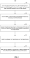
- One embodiment illustrated herein includes a method that includes acts for controlling a mirror in a MEMS based projector.
- the method comprising iteratively performing various acts.
- the method includes inputting a time domain target wave array, with target elements, to a system for a MEMS coupled to the mirror of the projector.
- the time domain target wave array includes a set of n target elements.
- the method further includes driving the driver to move the mirror using elements in a drive array comprising a set of drive elements.
- the method further includes sampling a time domain output wave for the movement of the mirror to construct an output wave array with output elements corresponding to the target elements.
- the method further includes identifying errors between the target elements and the output elements.
- the method further includes modifying the drive elements in the drive array to attempt to minimize the errors when driving the MEMS on subsequent drive cycles.
- Element by element errors are then calculated between the elements of the target wave array and corresponding elements of the output wave array. These errors are then used by a controller to adjust the drive array elements to attempt to minimize the errors between the target wave array elements and the output wave array elements. Note that in some embodiments, the controller solves a set of linear equations that use the error as input to identify how the drive array elements should be modified.
- Figure 1 a graphical representation of a typical raster scan on a display surface 100 is shown.
- a laser beam path is shown.
- Figure 1 illustrates drawing intervals 102, horizontal blanking intervals 104, and a vertical blanking interval 106.
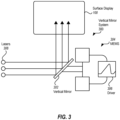
- a horizontal mirror and vertical mirror are manipulated to manipulate how light can be reflected from lasers.
- the vertical mirror system 300 includes a vertical mirror 302. Movement of the vertical mirror 302 is controlled by a MEMS 304.
- the MEMS 304 is controlled by a driver 306.
- the driver 306 attempts to control movement of the vertical mirror 302 such that the movement of the vertical mirror 302 is consistent with the vertical control wave 200.
- the driver 306 will attempt to drive the MEMS 304 to move the vertical mirror 302 in a fashion such that light from the lasers 308 would be reflected off of the vertical mirror 302 and onto the display surface 100 consistent with the vertical movement shown in Figure 1 if the lasers 308 were constantly illuminated.
- the lasers are not illuminated during the horizontal blanking interval 104 and the vertical blanking interval 106.
- the movement of the vertical mirror 302 be manipulated in a fashion defined by the vertical control wave 200, it is often the case that such movement cannot be strictly achieved. That is, in an open-loop system, if the driver 306 were to simply drive the MEMS 304 using the vertical control wave 200, the movement of the mirror 302 would not match the vertical control wave 200. This may be due to aging components in the MEMS 304, aging components in the driver 306, manufacturing differences between different instances vertical mirror systems, the mass of components in the vertical mirror system 300, or for other reasons.
- Embodiments illustrated herein implement a controller that directly servos each of several control points used to establish a drive waveform used to drive the driver 306.
- the controller operates in the time domain.
- the controller is able to use many different basis functions such as square, Gaussian, triangle, etc.
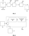
- the vertical mirror system 400 includes a MEMS 404 configured to cause a vertical mirror, such as the vertical mirror 302 illustrated in Figure 3 , to move.
- the MEMS 404 is driven by a compensator 405 which will be discussed in more detail below.
- a sensor 410 monitors the actual movement of the vertical mirror 402.
- each element of the target wave array 412 includes a magnitude value. Further, each element corresponds to a particular time in one cycle of the vertical control wave 200.
- a graphical representation 414 shows what the values of the target wave array 412 might look like if plotted against time.
- the sensor 410 may be implemented in a number of different fashions.
- the sensor 410 may be a Piezo-resistive strain sensor coupled to the vertical mirror 402 to detect movement of the vertical mirror 402, which can be used to create the output wave array 418. That is, the magnitude of the movement of the vertical mirror 402 can be converted to values stored in the output wave array 418 at various times corresponding to times in a cycle of vertical mirror movement.
- the vertical mirror system 400 works by comparing output from the sensor 410 (i.e. MEMS angle feedback), in the form of the output wave array 418 to the target wave array 412 in response to the drive array 422 applied to the MEMS 404 to compute an error signal.
- the vertical mirror system 400 operates on complete frames of data and maintains an integration of the error signal at each control point which is used as the drive signal (in the form of the drive array 422) for the high bandwidth loop driving the MEMS.
- embodiments will perform an impulse input by appropriately modifying the training array 504 multiple times such that each element of the training array 504 can be input as an impulse input into the MEMS 404 and an output wave array 418 generated for each of the impulse inputs.
- the training array 504 has 50 elements
- calibration is performed by inputting 50 different iterations of the training array 504, where each iteration has a different element as an impulse element into the MEMS 404.
- 50 different output wave arrays are collected, one for each input of the training array 504.
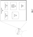
- the disclosed embodiments may comprise or utilize a special-purpose or general-purpose computer including computer hardware, such as, for example, one or more processors (such the hardware processing unit 705) and system memory (such as storage 725), as discussed in greater detail below.
- Embodiments also include physical and other computer-readable media for carrying or storing computer-executable instructions and/or data structures.
- Such computer-readable media can be any available media that can be accessed by a general-purpose or special-purpose computer system.
- Computer-readable media that store computer-executable instructions in the form of data are physical computer storage media.
- Computer-readable media that carry computer-executable instructions are transmission media.
- the current embodiments can comprise at least two distinctly different kinds of computer-readable media: computer storage media and transmission media.
- Computer storage media are hardware storage devices, such as RAM, ROM, EEPROM, CD-ROM, solid state drives (SSDs) that are based on RAM, Flash memory, phase-change memory (PCM), or other types of memory, or other optical disk storage, magnetic disk storage or other magnetic storage devices, or any other medium that can be used to store desired program code means in the form of computer-executable instructions, data, or data structures and that can be accessed by a general-purpose or special-purpose computer.
- RAM random access memory
- ROM read-only memory
- EEPROM electrically erasable programmable read-only memory
- CD-ROM Compact Disk Read Only Memory
- SSDs solid state drives
- PCM phase-change memory
- program code means in the form of computer-executable instructions or data structures can be transferred automatically from transmission media to computer storage media (or vice versa).
- program code means in the form of computer-executable instructions or data structures received over a network or data link can be buffered in RAM within a network interface module (e.g., a network interface card or "NIC") and then eventually transferred to computer system RAM and/or to less volatile computer storage media at a computer system.
- NIC network interface card
- the method 800 further includes identifying errors between the target elements and the output elements (act 808).
- the subtraction element 416 may identify errors, on an element by element basis, between the target wave array 412 and the output wave array 418.
- the method 800 may further include Identifying errors between the drive elements and the output elements and driving the driver to reduce the errors between the drive elements and the output elements. An example of this is illustrated in Figure 6 .
Landscapes
- Physics & Mathematics (AREA)
- Optics & Photonics (AREA)
- General Physics & Mathematics (AREA)
- Engineering & Computer Science (AREA)
- Multimedia (AREA)
- Signal Processing (AREA)
- Computer Hardware Design (AREA)
- Theoretical Computer Science (AREA)
- Mechanical Light Control Or Optical Switches (AREA)
- Transforming Electric Information Into Light Information (AREA)
- Mechanical Optical Scanning Systems (AREA)
Claims (13)
- Verfahren (800) zum Steuern eines Spiegels (402) in einem MEMS-basierten Projektor, wobei das Verfahren das iterative Durchführen des Folgenden umfasst:Eingeben (802) eines Zeitbereichs-Zielwellenarrays (412) mit Zielelementen in ein System (400) für ein MEMS (404), das mit dem Spiegel (402) des Projektors gekoppelt ist, wobei das Zeitbereichs-Zielwellenarray einen Satz von n Zielelementen umfasst;Antreiben (804) eines Treibers (405), um den Spiegel (402) unter Verwendung von Elementen in einer Antriebsarray (420) zu bewegen, die einen Satz von Antriebselementen umfasst;Abtasten (806) einer Zeitbereichs-Ausgangswelle zur Bewegung des Spiegels (402), um ein Ausgangswellenarray (418) mit Ausgangselementen aufzubauen, die den Zielelementen entsprechen;Erkennen (808) von Fehlern zwischen den Zielelementen und den Ausgangselementen; undModifizieren (810) der Antriebselemente im Antriebsarray (420), um zu versuchen, die Fehler beim Ansteuern des MEMS (404) in nachfolgenden Antriebszyklen zu minimieren, wobei Modifikationen an den Antriebselementen im Antriebsarray (420) zumindest teilweise auf einer Impulsantwort für jedes Ausgangselement basieren, die durch individuelles Antreiben der Eingabe des Treibers mit einer Impulseingabe (502) für jedes der Antriebselemente bestimmt wird.
- Verfahren nach Anspruch 1, wobei das Modifizieren (810) der Antriebselemente das Lösen eines Satzes linearer Gleichungen umfasst, die n Antwortausgaben auf n Eingaben in den Treiber (405) definieren.
- Verfahren nach Anspruch 2, wobei das Lösen des Satzes linearer Gleichungen das Anwenden einer Matrix auf die Fehler umfasst.
- Verfahren nach Anspruch 1, wobei das Abtasten (806) einer Zeitbereichs-Ausgangswelle für die Bewegung des Spiegels (402) zum Aufbau eines Ausgangswellenarrays (418) mit Ausgangselementen, die den Zielelementen entsprechen, das Abtasten einer Bewegung des Spiegels (402) unter Verwendung eines piezoresistiven Dehnungssensors (410) umfasst.
- Verfahren nach Anspruch 1, weiter umfassend:
Erkennen von Fehlern zwischen den Antriebselementen und den Ausgangselementen; und Ansteuern des MEMS (404), um die Fehler zwischen den Antriebselementen und den Ausgangselementen zu reduzieren. - Verfahren nach Anspruch 1, wobei das Zielwellenarray (412) eine modifizierte Sägezahnwelle (200) modelliert.
- Computersystem (700), umfassend:einen MEMS-basierten Projektor (720), der einen Spiegel (402) umfasst;einen oder mehrere Prozessoren (705); undein oder mehrere computerlesbare Medien (725), aufweisend darauf gespeicherte Anweisungen, die von dem einen oder den mehreren Prozessoren (705) ausführbar sind, um das Computersystem (700) zu konfigurieren, den Spiegel (402) im MEMS-basierten Projektor (720) zu steuern, einschließlich Anweisungen, die ausführbar sind, um das Computersystem (700) zu konfigurieren, mindestens das Folgende durchzuführen:Eingeben (802) eines Zeitbereichs-Zielwellenarrays (412) mit Zielelementen in ein System (400) für ein MEMS (404), das mit dem Spiegel (402) des Projektors (720) gekoppelt ist, wobei das Zeitbereichs-Zielwellenarray (412) einen Satz von n Zielelementen umfasst;Antreiben (804) eines Treibers (405), um den Spiegel (402) unter Verwendung von Elementen in einem Antriebsarray (420) zu bewegen, das einen Satz von Antriebselementen umfasst;Abtasten (806) einer Zeitbereichs-Ausgangswelle zur Bewegung des Spiegels (402), um ein Ausgangswellenarray (418) mit Ausgangselementen aufzubauen, die den Zielelementen entsprechen;Erkennen (808) von Fehlern zwischen den Zielelementen und den Ausgangselementen; undModifizieren (810) der Antriebselemente im Antriebsarray (420), um zu versuchen, die Fehler beim Ansteuern des MEMS (404) in nachfolgenden Antriebszyklen zu minimieren, wobei Modifikationen an den Antriebselementen im Antriebsarray (420) zumindest teilweise auf einer Impulsantwort für jedes Ausgangselement basieren, die durch individuelles Antreiben der Eingabe des Treibers mit einer Impulseingabe (502) für jedes der Antriebselemente bestimmt wird.
- Computersystem (700) nach Anspruch 7, wobei das Modifizieren (810) der Antriebselemente das Lösen eines Satzes linearer Gleichungen umfasst, die n Antwortausgaben auf n Eingaben in den Treiber (405) definieren.
- Computersystem (700) nach Anspruch 8, wobei das Lösen des Satzes linearer Gleichungen das Anwenden einer Matrix auf die Fehler umfasst.
- Computersystem (700) nach Anspruch 7, wobei das Abtasten einer Zeitbereichs-Ausgangswelle für eine Bewegung des Spiegels (402) zum Aufbau eines Ausgangswellenarrays (418) mit Ausgangselementen, die den Zielelementen entsprechen, das Abtasten einer Bewegung des Spiegels (402) unter Verwendung eines piezoresistiven Dehnungssensors (410) umfasst
- Computersystem (700) nach Anspruch 7, wobei auf dem einen oder den mehreren computerlesbaren Medien (725) weiter Anweisungen gespeichert sind, die von dem einen oder den mehreren Prozessoren (705) ausführbar sind, um das Computersystem (700) zu konfigurieren, mindestens das Folgende durchzuführen:Erkennen von Fehlern zwischen den Antriebselementen und den Ausgangselementen; undAnsteuern des MEMS (404), um die Fehler zwischen den Antriebselementen und den Ausgangselementen zu reduzieren.
- Computersystem (700) nach Anspruch 7, wobei das Zielwellenarray (412) eine modifizierte Sägezahnwelle (200) modelliert.
- Computerlesbares Speichermedium (725), aufweisend darauf gespeicherte Anweisungen, die von einem oder mehreren Prozessoren (705) ausführbar sind, um ein Computersystem (700) zu konfigurieren, einen Spiegel (402) in einem MEMS-basierten Projektor (720) zu steuern, einschließlich Anweisungen, die ausführbar sind, um das Computersystem (700) zu konfigurieren, mindestens das Folgende durchzuführen:Eingeben (802) eines Zeitbereichs-Zielwellenarrays (412) mit Zielelementen in ein System (400) für ein MEMS (404), das mit dem Spiegel (402) des Projektors (720) gekoppelt ist, wobei das Zeitbereichs-Zielwellenarray (412) einen Satz von n Zielelementen umfasst;Antreiben (804) eines Treibers (405), um den Spiegel (402) unter Verwendung von Elementen in einem Antriebsarray (420) zu bewegen, das einen Satz von Antriebselementen umfasst;Abtasten (806) einer Zeitbereichs-Ausgangswelle zur Bewegung des Spiegels (402), um ein Ausgangswellenarray (418) mit Ausgangselementen aufzubauen, die den Zielelementen entsprechen;Erkennen (808) von Fehlern zwischen den Zielelementen und den Ausgangselementen; undModifizieren (810) der Antriebselemente im Antriebsarray (420), um zu versuchen, die Fehler beim Ansteuern des MEMS (404) in nachfolgenden Antriebszyklen zu minimieren, wobei Modifikationen an den Antriebselementen im Antriebsarray (420) zumindest teilweise auf einer Impulsantwort für jedes Ausgangselement basieren, die durch individuelles Antreiben der Eingabe des Treibers (405) mit einer Impulseingabe (502) für jedes der Antriebselemente bestimmt wird.
Applications Claiming Priority (2)
| Application Number | Priority Date | Filing Date | Title |
|---|---|---|---|
| US16/421,241 US11039111B2 (en) | 2019-05-23 | 2019-05-23 | MEMS control method to provide trajectory control |
| PCT/US2020/028169 WO2020236344A1 (en) | 2019-05-23 | 2020-04-15 | Mems control method to provide trajectory control |
Publications (2)
| Publication Number | Publication Date |
|---|---|
| EP3973345A1 EP3973345A1 (de) | 2022-03-30 |
| EP3973345B1 true EP3973345B1 (de) | 2023-12-20 |
Family
ID=70465574
Family Applications (1)
| Application Number | Title | Priority Date | Filing Date |
|---|---|---|---|
| EP20722210.0A Active EP3973345B1 (de) | 2019-05-23 | 2020-04-15 | Mems steuerungsverfahren zur steuerung der bahnsteuerung |
Country Status (3)
| Country | Link |
|---|---|
| US (2) | US11039111B2 (de) |
| EP (1) | EP3973345B1 (de) |
| WO (1) | WO2020236344A1 (de) |
Families Citing this family (3)
| Publication number | Priority date | Publication date | Assignee | Title |
|---|---|---|---|---|
| US11039111B2 (en) * | 2019-05-23 | 2021-06-15 | Microsoft Technology Licensing, Llc | MEMS control method to provide trajectory control |
| US11841497B2 (en) * | 2020-12-02 | 2023-12-12 | Politecnico Di Milano | Closed-loop position control of MEMS micromirrors |
| TW202505913A (zh) * | 2023-07-19 | 2025-02-01 | 國立臺灣大學 | 影像擷取裝置及其運作方法 |
Family Cites Families (13)
| Publication number | Priority date | Publication date | Assignee | Title |
|---|---|---|---|---|
| US8446342B2 (en) | 2002-05-17 | 2013-05-21 | Microvision, Inc. | Projection system with multi-phased scanning trajectory |
| US8624177B2 (en) * | 2006-12-16 | 2014-01-07 | David Campion | Refined optical system |
| US8904560B2 (en) | 2007-05-07 | 2014-12-02 | Bruker Nano, Inc. | Closed loop controller and method for fast scanning probe microscopy |
| WO2009049272A2 (en) | 2007-10-10 | 2009-04-16 | Gerard Dirk Smits | Image projector with reflected light tracking |
| US7952783B2 (en) * | 2008-09-22 | 2011-05-31 | Microvision, Inc. | Scanning mirror control |
| US8371698B2 (en) | 2010-04-12 | 2013-02-12 | Microvision, Inc. | Scanning projector with vertical interpolation onto horizontal trajectory |
| US8711186B2 (en) | 2011-05-02 | 2014-04-29 | Microvision, Inc. | Scanning projection apparatus with tangential compensation |
| JP5864177B2 (ja) | 2011-09-15 | 2016-02-17 | 船井電機株式会社 | プロジェクタおよびプロジェクタシステム |
| JP6151051B2 (ja) | 2013-03-08 | 2017-06-21 | 株式会社日立エルジーデータストレージ | レーザ投射表示装置およびそのレーザ駆動制御方法 |
| JP2016148763A (ja) | 2015-02-12 | 2016-08-18 | スタンレー電気株式会社 | 映像投射装置 |
| JP6604816B2 (ja) | 2015-10-28 | 2019-11-13 | スタンレー電気株式会社 | 映像投射装置及びmemsミラーの制御方法 |
| ITUA20162121A1 (it) * | 2016-03-30 | 2017-09-30 | St Microelectronics Ltd | Metodo di controllo della posizione di uno specchio mems lineare con risoluzione e/o intensita' luminosa variabile |
| US11039111B2 (en) * | 2019-05-23 | 2021-06-15 | Microsoft Technology Licensing, Llc | MEMS control method to provide trajectory control |
-
2019
- 2019-05-23 US US16/421,241 patent/US11039111B2/en active Active
-
2020
- 2020-04-15 WO PCT/US2020/028169 patent/WO2020236344A1/en not_active Ceased
- 2020-04-15 EP EP20722210.0A patent/EP3973345B1/de active Active
-
2021
- 2021-05-20 US US17/326,027 patent/US11838693B2/en active Active
Also Published As
| Publication number | Publication date |
|---|---|
| US11838693B2 (en) | 2023-12-05 |
| US11039111B2 (en) | 2021-06-15 |
| US20210286169A1 (en) | 2021-09-16 |
| US20200374495A1 (en) | 2020-11-26 |
| WO2020236344A1 (en) | 2020-11-26 |
| EP3973345A1 (de) | 2022-03-30 |
Similar Documents
| Publication | Publication Date | Title |
|---|---|---|
| US11838693B2 (en) | MEMS control method to provide trajectory control | |
| US11713970B2 (en) | Positioning method, electronic device and computer readable storage medium | |
| US10605902B2 (en) | Motion compensation method and apparatus applicable to laser point cloud data | |
| US9588598B2 (en) | Efficient orientation estimation system using magnetic, angular rate, and gravity sensors | |
| US8831376B2 (en) | Image processing device, image processing method and storage medium | |
| US11800053B2 (en) | Method, device and computer readable storage medium for video frame interpolation | |
| CN106782260B (zh) | 用于虚拟现实运动场景的显示方法及装置 | |
| US20230353713A1 (en) | Amplitude and biphase control of mems scanning device | |
| WO2020205314A1 (en) | Trajectory estimation for a mems reflector | |
| CN111066081B (zh) | 用于补偿虚拟现实的图像显示中的可变显示设备等待时间的技术 | |
| US20210405351A1 (en) | Control loop for stabilizing a resonant frequency of a mirror of a laser beam scanning display | |
| US10140955B1 (en) | Display latency calibration for organic light emitting diode (OLED) display | |
| US10553164B1 (en) | Display latency calibration for liquid crystal display | |
| US11985416B2 (en) | Electronic device and method with independent time point management | |
| WO2020121755A1 (ja) | 推定装置、訓練装置、推定方法及び訓練方法 | |
| EP3924959B1 (de) | Adaptive regelung für laserstrahlabtastanzeigen | |
| US12444333B1 (en) | Utilizing noise threshold conditions for controlling scanning mirrors | |
| JP2022138111A (ja) | 情報処理装置、情報処理方法及びプログラム | |
| CN121661216B (zh) | 一种车载三维场景渲染方法、设备、存储介质及程序产品 | |
| CN116661140B (zh) | 一种用于提高静电mems微镜扫描角度的优化方法及系统 |
Legal Events
| Date | Code | Title | Description |
|---|---|---|---|
| STAA | Information on the status of an ep patent application or granted ep patent |
Free format text: STATUS: UNKNOWN |
|
| STAA | Information on the status of an ep patent application or granted ep patent |
Free format text: STATUS: THE INTERNATIONAL PUBLICATION HAS BEEN MADE |
|
| PUAI | Public reference made under article 153(3) epc to a published international application that has entered the european phase |
Free format text: ORIGINAL CODE: 0009012 |
|
| STAA | Information on the status of an ep patent application or granted ep patent |
Free format text: STATUS: REQUEST FOR EXAMINATION WAS MADE |
|
| 17P | Request for examination filed |
Effective date: 20211001 |
|
| AK | Designated contracting states |
Kind code of ref document: A1 Designated state(s): AL AT BE BG CH CY CZ DE DK EE ES FI FR GB GR HR HU IE IS IT LI LT LU LV MC MK MT NL NO PL PT RO RS SE SI SK SM TR |
|
| DAV | Request for validation of the european patent (deleted) | ||
| DAX | Request for extension of the european patent (deleted) | ||
| GRAP | Despatch of communication of intention to grant a patent |
Free format text: ORIGINAL CODE: EPIDOSNIGR1 |
|
| STAA | Information on the status of an ep patent application or granted ep patent |
Free format text: STATUS: GRANT OF PATENT IS INTENDED |
|
| INTG | Intention to grant announced |
Effective date: 20230829 |
|
| GRAS | Grant fee paid |
Free format text: ORIGINAL CODE: EPIDOSNIGR3 |
|
| GRAA | (expected) grant |
Free format text: ORIGINAL CODE: 0009210 |
|
| STAA | Information on the status of an ep patent application or granted ep patent |
Free format text: STATUS: THE PATENT HAS BEEN GRANTED |
|
| AK | Designated contracting states |
Kind code of ref document: B1 Designated state(s): AL AT BE BG CH CY CZ DE DK EE ES FI FR GB GR HR HU IE IS IT LI LT LU LV MC MK MT NL NO PL PT RO RS SE SI SK SM TR |
|
| P01 | Opt-out of the competence of the unified patent court (upc) registered |
Effective date: 20231109 |
|
| REG | Reference to a national code |
Ref country code: GB Ref legal event code: FG4D |
|
| REG | Reference to a national code |
Ref country code: DE Ref legal event code: R096 Ref document number: 602020023057 Country of ref document: DE |
|
| REG | Reference to a national code |
Ref country code: CH Ref legal event code: EP |
|
| REG | Reference to a national code |
Ref country code: IE Ref legal event code: FG4D |
|
| REG | Reference to a national code |
Ref country code: NL Ref legal event code: FP |
|
| PG25 | Lapsed in a contracting state [announced via postgrant information from national office to epo] |
Ref country code: GR Free format text: LAPSE BECAUSE OF FAILURE TO SUBMIT A TRANSLATION OF THE DESCRIPTION OR TO PAY THE FEE WITHIN THE PRESCRIBED TIME-LIMIT Effective date: 20240321 |
|
| REG | Reference to a national code |
Ref country code: LT Ref legal event code: MG9D |
|
| PG25 | Lapsed in a contracting state [announced via postgrant information from national office to epo] |
Ref country code: LT Free format text: LAPSE BECAUSE OF FAILURE TO SUBMIT A TRANSLATION OF THE DESCRIPTION OR TO PAY THE FEE WITHIN THE PRESCRIBED TIME-LIMIT Effective date: 20231220 |
|
| PG25 | Lapsed in a contracting state [announced via postgrant information from national office to epo] |
Ref country code: ES Free format text: LAPSE BECAUSE OF FAILURE TO SUBMIT A TRANSLATION OF THE DESCRIPTION OR TO PAY THE FEE WITHIN THE PRESCRIBED TIME-LIMIT Effective date: 20231220 |
|
| PG25 | Lapsed in a contracting state [announced via postgrant information from national office to epo] |
Ref country code: LT Free format text: LAPSE BECAUSE OF FAILURE TO SUBMIT A TRANSLATION OF THE DESCRIPTION OR TO PAY THE FEE WITHIN THE PRESCRIBED TIME-LIMIT Effective date: 20231220 Ref country code: GR Free format text: LAPSE BECAUSE OF FAILURE TO SUBMIT A TRANSLATION OF THE DESCRIPTION OR TO PAY THE FEE WITHIN THE PRESCRIBED TIME-LIMIT Effective date: 20240321 Ref country code: FI Free format text: LAPSE BECAUSE OF FAILURE TO SUBMIT A TRANSLATION OF THE DESCRIPTION OR TO PAY THE FEE WITHIN THE PRESCRIBED TIME-LIMIT Effective date: 20231220 Ref country code: ES Free format text: LAPSE BECAUSE OF FAILURE TO SUBMIT A TRANSLATION OF THE DESCRIPTION OR TO PAY THE FEE WITHIN THE PRESCRIBED TIME-LIMIT Effective date: 20231220 Ref country code: BG Free format text: LAPSE BECAUSE OF FAILURE TO SUBMIT A TRANSLATION OF THE DESCRIPTION OR TO PAY THE FEE WITHIN THE PRESCRIBED TIME-LIMIT Effective date: 20240320 |
|
| REG | Reference to a national code |
Ref country code: AT Ref legal event code: MK05 Ref document number: 1642951 Country of ref document: AT Kind code of ref document: T Effective date: 20231220 |
|
| PG25 | Lapsed in a contracting state [announced via postgrant information from national office to epo] |
Ref country code: SE Free format text: LAPSE BECAUSE OF FAILURE TO SUBMIT A TRANSLATION OF THE DESCRIPTION OR TO PAY THE FEE WITHIN THE PRESCRIBED TIME-LIMIT Effective date: 20231220 Ref country code: RS Free format text: LAPSE BECAUSE OF FAILURE TO SUBMIT A TRANSLATION OF THE DESCRIPTION OR TO PAY THE FEE WITHIN THE PRESCRIBED TIME-LIMIT Effective date: 20231220 Ref country code: NO Free format text: LAPSE BECAUSE OF FAILURE TO SUBMIT A TRANSLATION OF THE DESCRIPTION OR TO PAY THE FEE WITHIN THE PRESCRIBED TIME-LIMIT Effective date: 20240320 Ref country code: LV Free format text: LAPSE BECAUSE OF FAILURE TO SUBMIT A TRANSLATION OF THE DESCRIPTION OR TO PAY THE FEE WITHIN THE PRESCRIBED TIME-LIMIT Effective date: 20231220 Ref country code: HR Free format text: LAPSE BECAUSE OF FAILURE TO SUBMIT A TRANSLATION OF THE DESCRIPTION OR TO PAY THE FEE WITHIN THE PRESCRIBED TIME-LIMIT Effective date: 20231220 |
|
| PGFP | Annual fee paid to national office [announced via postgrant information from national office to epo] |
Ref country code: FR Payment date: 20240320 Year of fee payment: 5 |
|
| PG25 | Lapsed in a contracting state [announced via postgrant information from national office to epo] |
Ref country code: IS Free format text: LAPSE BECAUSE OF FAILURE TO SUBMIT A TRANSLATION OF THE DESCRIPTION OR TO PAY THE FEE WITHIN THE PRESCRIBED TIME-LIMIT Effective date: 20240420 |
|
| PG25 | Lapsed in a contracting state [announced via postgrant information from national office to epo] |
Ref country code: AT Free format text: LAPSE BECAUSE OF FAILURE TO SUBMIT A TRANSLATION OF THE DESCRIPTION OR TO PAY THE FEE WITHIN THE PRESCRIBED TIME-LIMIT Effective date: 20231220 Ref country code: CZ Free format text: LAPSE BECAUSE OF FAILURE TO SUBMIT A TRANSLATION OF THE DESCRIPTION OR TO PAY THE FEE WITHIN THE PRESCRIBED TIME-LIMIT Effective date: 20231220 |
|
| PG25 | Lapsed in a contracting state [announced via postgrant information from national office to epo] |
Ref country code: SK Free format text: LAPSE BECAUSE OF FAILURE TO SUBMIT A TRANSLATION OF THE DESCRIPTION OR TO PAY THE FEE WITHIN THE PRESCRIBED TIME-LIMIT Effective date: 20231220 |
|
| PG25 | Lapsed in a contracting state [announced via postgrant information from national office to epo] |
Ref country code: SM Free format text: LAPSE BECAUSE OF FAILURE TO SUBMIT A TRANSLATION OF THE DESCRIPTION OR TO PAY THE FEE WITHIN THE PRESCRIBED TIME-LIMIT Effective date: 20231220 Ref country code: SK Free format text: LAPSE BECAUSE OF FAILURE TO SUBMIT A TRANSLATION OF THE DESCRIPTION OR TO PAY THE FEE WITHIN THE PRESCRIBED TIME-LIMIT Effective date: 20231220 Ref country code: RO Free format text: LAPSE BECAUSE OF FAILURE TO SUBMIT A TRANSLATION OF THE DESCRIPTION OR TO PAY THE FEE WITHIN THE PRESCRIBED TIME-LIMIT Effective date: 20231220 Ref country code: IT Free format text: LAPSE BECAUSE OF FAILURE TO SUBMIT A TRANSLATION OF THE DESCRIPTION OR TO PAY THE FEE WITHIN THE PRESCRIBED TIME-LIMIT Effective date: 20231220 Ref country code: IS Free format text: LAPSE BECAUSE OF FAILURE TO SUBMIT A TRANSLATION OF THE DESCRIPTION OR TO PAY THE FEE WITHIN THE PRESCRIBED TIME-LIMIT Effective date: 20240420 Ref country code: EE Free format text: LAPSE BECAUSE OF FAILURE TO SUBMIT A TRANSLATION OF THE DESCRIPTION OR TO PAY THE FEE WITHIN THE PRESCRIBED TIME-LIMIT Effective date: 20231220 Ref country code: CZ Free format text: LAPSE BECAUSE OF FAILURE TO SUBMIT A TRANSLATION OF THE DESCRIPTION OR TO PAY THE FEE WITHIN THE PRESCRIBED TIME-LIMIT Effective date: 20231220 Ref country code: AT Free format text: LAPSE BECAUSE OF FAILURE TO SUBMIT A TRANSLATION OF THE DESCRIPTION OR TO PAY THE FEE WITHIN THE PRESCRIBED TIME-LIMIT Effective date: 20231220 |
|
| PG25 | Lapsed in a contracting state [announced via postgrant information from national office to epo] |
Ref country code: PL Free format text: LAPSE BECAUSE OF FAILURE TO SUBMIT A TRANSLATION OF THE DESCRIPTION OR TO PAY THE FEE WITHIN THE PRESCRIBED TIME-LIMIT Effective date: 20231220 Ref country code: PT Free format text: LAPSE BECAUSE OF FAILURE TO SUBMIT A TRANSLATION OF THE DESCRIPTION OR TO PAY THE FEE WITHIN THE PRESCRIBED TIME-LIMIT Effective date: 20240422 |
|
| PG25 | Lapsed in a contracting state [announced via postgrant information from national office to epo] |
Ref country code: PT Free format text: LAPSE BECAUSE OF FAILURE TO SUBMIT A TRANSLATION OF THE DESCRIPTION OR TO PAY THE FEE WITHIN THE PRESCRIBED TIME-LIMIT Effective date: 20240422 Ref country code: PL Free format text: LAPSE BECAUSE OF FAILURE TO SUBMIT A TRANSLATION OF THE DESCRIPTION OR TO PAY THE FEE WITHIN THE PRESCRIBED TIME-LIMIT Effective date: 20231220 |
|
| REG | Reference to a national code |
Ref country code: DE Ref legal event code: R097 Ref document number: 602020023057 Country of ref document: DE |
|
| PG25 | Lapsed in a contracting state [announced via postgrant information from national office to epo] |
Ref country code: DK Free format text: LAPSE BECAUSE OF FAILURE TO SUBMIT A TRANSLATION OF THE DESCRIPTION OR TO PAY THE FEE WITHIN THE PRESCRIBED TIME-LIMIT Effective date: 20231220 |
|
| PLBE | No opposition filed within time limit |
Free format text: ORIGINAL CODE: 0009261 |
|
| STAA | Information on the status of an ep patent application or granted ep patent |
Free format text: STATUS: NO OPPOSITION FILED WITHIN TIME LIMIT |
|
| PG25 | Lapsed in a contracting state [announced via postgrant information from national office to epo] |
Ref country code: SI Free format text: LAPSE BECAUSE OF FAILURE TO SUBMIT A TRANSLATION OF THE DESCRIPTION OR TO PAY THE FEE WITHIN THE PRESCRIBED TIME-LIMIT Effective date: 20231220 |
|
| PG25 | Lapsed in a contracting state [announced via postgrant information from national office to epo] |
Ref country code: SI Free format text: LAPSE BECAUSE OF FAILURE TO SUBMIT A TRANSLATION OF THE DESCRIPTION OR TO PAY THE FEE WITHIN THE PRESCRIBED TIME-LIMIT Effective date: 20231220 Ref country code: DK Free format text: LAPSE BECAUSE OF FAILURE TO SUBMIT A TRANSLATION OF THE DESCRIPTION OR TO PAY THE FEE WITHIN THE PRESCRIBED TIME-LIMIT Effective date: 20231220 |
|
| PG25 | Lapsed in a contracting state [announced via postgrant information from national office to epo] |
Ref country code: MC Free format text: LAPSE BECAUSE OF FAILURE TO SUBMIT A TRANSLATION OF THE DESCRIPTION OR TO PAY THE FEE WITHIN THE PRESCRIBED TIME-LIMIT Effective date: 20231220 |
|
| 26N | No opposition filed |
Effective date: 20240923 |
|
| PG25 | Lapsed in a contracting state [announced via postgrant information from national office to epo] |
Ref country code: MC Free format text: LAPSE BECAUSE OF FAILURE TO SUBMIT A TRANSLATION OF THE DESCRIPTION OR TO PAY THE FEE WITHIN THE PRESCRIBED TIME-LIMIT Effective date: 20231220 |
|
| REG | Reference to a national code |
Ref country code: CH Ref legal event code: PL |
|
| PG25 | Lapsed in a contracting state [announced via postgrant information from national office to epo] |
Ref country code: LU Free format text: LAPSE BECAUSE OF NON-PAYMENT OF DUE FEES Effective date: 20240415 |
|
| REG | Reference to a national code |
Ref country code: BE Ref legal event code: MM Effective date: 20240430 |
|
| PG25 | Lapsed in a contracting state [announced via postgrant information from national office to epo] |
Ref country code: LU Free format text: LAPSE BECAUSE OF NON-PAYMENT OF DUE FEES Effective date: 20240415 |
|
| PG25 | Lapsed in a contracting state [announced via postgrant information from national office to epo] |
Ref country code: BE Free format text: LAPSE BECAUSE OF NON-PAYMENT OF DUE FEES Effective date: 20240430 |
|
| PG25 | Lapsed in a contracting state [announced via postgrant information from national office to epo] |
Ref country code: BE Free format text: LAPSE BECAUSE OF NON-PAYMENT OF DUE FEES Effective date: 20240430 Ref country code: CH Free format text: LAPSE BECAUSE OF NON-PAYMENT OF DUE FEES Effective date: 20240430 |
|
| PG25 | Lapsed in a contracting state [announced via postgrant information from national office to epo] |
Ref country code: IE Free format text: LAPSE BECAUSE OF NON-PAYMENT OF DUE FEES Effective date: 20240415 |
|
| PGFP | Annual fee paid to national office [announced via postgrant information from national office to epo] |
Ref country code: DE Payment date: 20250319 Year of fee payment: 6 |
|
| PG25 | Lapsed in a contracting state [announced via postgrant information from national office to epo] |
Ref country code: CY Free format text: LAPSE BECAUSE OF FAILURE TO SUBMIT A TRANSLATION OF THE DESCRIPTION OR TO PAY THE FEE WITHIN THE PRESCRIBED TIME-LIMIT; INVALID AB INITIO Effective date: 20200415 |
|
| PG25 | Lapsed in a contracting state [announced via postgrant information from national office to epo] |
Ref country code: HU Free format text: LAPSE BECAUSE OF FAILURE TO SUBMIT A TRANSLATION OF THE DESCRIPTION OR TO PAY THE FEE WITHIN THE PRESCRIBED TIME-LIMIT; INVALID AB INITIO Effective date: 20200415 |
|
| PG25 | Lapsed in a contracting state [announced via postgrant information from national office to epo] |
Ref country code: FR Free format text: LAPSE BECAUSE OF NON-PAYMENT OF DUE FEES Effective date: 20250430 |
|
| PGFP | Annual fee paid to national office [announced via postgrant information from national office to epo] |
Ref country code: GB Payment date: 20260319 Year of fee payment: 7 |
|
| PGFP | Annual fee paid to national office [announced via postgrant information from national office to epo] |
Ref country code: NL Payment date: 20260319 Year of fee payment: 7 |