EP3973243B1 - Échangeur de chaleur à plaques et procédé de fabrication d'un échangeur de chaleur à plaques - Google Patents
Échangeur de chaleur à plaques et procédé de fabrication d'un échangeur de chaleur à plaques Download PDFInfo
- Publication number
- EP3973243B1 EP3973243B1 EP20725687.6A EP20725687A EP3973243B1 EP 3973243 B1 EP3973243 B1 EP 3973243B1 EP 20725687 A EP20725687 A EP 20725687A EP 3973243 B1 EP3973243 B1 EP 3973243B1
- Authority
- EP
- European Patent Office
- Prior art keywords
- plate
- heat exchanger
- annular flat
- end plate
- flat area
- Prior art date
- Legal status (The legal status is an assumption and is not a legal conclusion. Google has not performed a legal analysis and makes no representation as to the accuracy of the status listed.)
- Active
Links
- 238000004519 manufacturing process Methods 0.000 title claims description 6
- 238000005728 strengthening Methods 0.000 claims description 20
- 238000003825 pressing Methods 0.000 claims description 15
- 238000000034 method Methods 0.000 claims description 11
- 238000005304 joining Methods 0.000 claims description 7
- 238000005520 cutting process Methods 0.000 claims description 6
- 239000000463 material Substances 0.000 description 4
- 238000005219 brazing Methods 0.000 description 2
- 239000012530 fluid Substances 0.000 description 2
- 239000002184 metal Substances 0.000 description 2
- 238000004891 communication Methods 0.000 description 1
- 230000001419 dependent effect Effects 0.000 description 1
- 238000007789 sealing Methods 0.000 description 1
Images

Classifications
-
- F—MECHANICAL ENGINEERING; LIGHTING; HEATING; WEAPONS; BLASTING
- F28—HEAT EXCHANGE IN GENERAL
- F28D—HEAT-EXCHANGE APPARATUS, NOT PROVIDED FOR IN ANOTHER SUBCLASS, IN WHICH THE HEAT-EXCHANGE MEDIA DO NOT COME INTO DIRECT CONTACT
- F28D9/00—Heat-exchange apparatus having stationary plate-like or laminated conduit assemblies for both heat-exchange media, the media being in contact with different sides of a conduit wall
- F28D9/0031—Heat-exchange apparatus having stationary plate-like or laminated conduit assemblies for both heat-exchange media, the media being in contact with different sides of a conduit wall the conduits for one heat-exchange medium being formed by paired plates touching each other
- F28D9/0043—Heat-exchange apparatus having stationary plate-like or laminated conduit assemblies for both heat-exchange media, the media being in contact with different sides of a conduit wall the conduits for one heat-exchange medium being formed by paired plates touching each other the plates having openings therein for circulation of at least one heat-exchange medium from one conduit to another
- F28D9/005—Heat-exchange apparatus having stationary plate-like or laminated conduit assemblies for both heat-exchange media, the media being in contact with different sides of a conduit wall the conduits for one heat-exchange medium being formed by paired plates touching each other the plates having openings therein for circulation of at least one heat-exchange medium from one conduit to another the plates having openings therein for both heat-exchange media
-
- F—MECHANICAL ENGINEERING; LIGHTING; HEATING; WEAPONS; BLASTING
- F28—HEAT EXCHANGE IN GENERAL
- F28F—DETAILS OF HEAT-EXCHANGE AND HEAT-TRANSFER APPARATUS, OF GENERAL APPLICATION
- F28F9/00—Casings; Header boxes; Auxiliary supports for elements; Auxiliary members within casings
- F28F9/02—Header boxes; End plates
-
- F—MECHANICAL ENGINEERING; LIGHTING; HEATING; WEAPONS; BLASTING
- F28—HEAT EXCHANGE IN GENERAL
- F28D—HEAT-EXCHANGE APPARATUS, NOT PROVIDED FOR IN ANOTHER SUBCLASS, IN WHICH THE HEAT-EXCHANGE MEDIA DO NOT COME INTO DIRECT CONTACT
- F28D9/00—Heat-exchange apparatus having stationary plate-like or laminated conduit assemblies for both heat-exchange media, the media being in contact with different sides of a conduit wall
-
- F—MECHANICAL ENGINEERING; LIGHTING; HEATING; WEAPONS; BLASTING
- F28—HEAT EXCHANGE IN GENERAL
- F28F—DETAILS OF HEAT-EXCHANGE AND HEAT-TRANSFER APPARATUS, OF GENERAL APPLICATION
- F28F3/00—Plate-like or laminated elements; Assemblies of plate-like or laminated elements
- F28F3/02—Elements or assemblies thereof with means for increasing heat-transfer area, e.g. with fins, with recesses, with corrugations
- F28F3/04—Elements or assemblies thereof with means for increasing heat-transfer area, e.g. with fins, with recesses, with corrugations the means being integral with the element
- F28F3/042—Elements or assemblies thereof with means for increasing heat-transfer area, e.g. with fins, with recesses, with corrugations the means being integral with the element in the form of local deformations of the element
- F28F3/046—Elements or assemblies thereof with means for increasing heat-transfer area, e.g. with fins, with recesses, with corrugations the means being integral with the element in the form of local deformations of the element the deformations being linear, e.g. corrugations
-
- F—MECHANICAL ENGINEERING; LIGHTING; HEATING; WEAPONS; BLASTING
- F28—HEAT EXCHANGE IN GENERAL
- F28F—DETAILS OF HEAT-EXCHANGE AND HEAT-TRANSFER APPARATUS, OF GENERAL APPLICATION
- F28F3/00—Plate-like or laminated elements; Assemblies of plate-like or laminated elements
- F28F3/08—Elements constructed for building-up into stacks, e.g. capable of being taken apart for cleaning
-
- F—MECHANICAL ENGINEERING; LIGHTING; HEATING; WEAPONS; BLASTING
- F28—HEAT EXCHANGE IN GENERAL
- F28F—DETAILS OF HEAT-EXCHANGE AND HEAT-TRANSFER APPARATUS, OF GENERAL APPLICATION
- F28F9/00—Casings; Header boxes; Auxiliary supports for elements; Auxiliary members within casings
- F28F9/02—Header boxes; End plates
- F28F9/0229—Double end plates; Single end plates with hollow spaces
-
- F—MECHANICAL ENGINEERING; LIGHTING; HEATING; WEAPONS; BLASTING
- F28—HEAT EXCHANGE IN GENERAL
- F28F—DETAILS OF HEAT-EXCHANGE AND HEAT-TRANSFER APPARATUS, OF GENERAL APPLICATION
- F28F9/00—Casings; Header boxes; Auxiliary supports for elements; Auxiliary members within casings
- F28F9/02—Header boxes; End plates
- F28F2009/0285—Other particular headers or end plates
-
- F—MECHANICAL ENGINEERING; LIGHTING; HEATING; WEAPONS; BLASTING
- F28—HEAT EXCHANGE IN GENERAL
- F28F—DETAILS OF HEAT-EXCHANGE AND HEAT-TRANSFER APPARATUS, OF GENERAL APPLICATION
- F28F2225/00—Reinforcing means
- F28F2225/04—Reinforcing means for conduits
-
- F—MECHANICAL ENGINEERING; LIGHTING; HEATING; WEAPONS; BLASTING
- F28—HEAT EXCHANGE IN GENERAL
- F28F—DETAILS OF HEAT-EXCHANGE AND HEAT-TRANSFER APPARATUS, OF GENERAL APPLICATION
- F28F2265/00—Safety or protection arrangements; Arrangements for preventing malfunction
- F28F2265/16—Safety or protection arrangements; Arrangements for preventing malfunction for preventing leakage
Definitions
- the present invention refers to a plate heat exchanger according to the preamble of claim 1.
- the invention also refers to a method of manufacturing a plate heat exchanger according to claim 11.
- US-A-4,987,955 discloses a plate heat exchanger comprising a plurality of plates extending in parallel with a main extension plane.
- the plates comprise a plurality of heat exchanger plates, two outer cover plates provided outside a respective one of the outermost heat exchanger plates, and a corrugated end plate provided between one of the outermost heat exchanger plates and one of the outer cover plates.
- the strengthening outer cover plates are plane and have a significantly greater thickness than the heat exchanger plates.
- the end plate has porthole areas that are closed.
- US-A-4987955 discloses a plate heat exchanger according to the preamble of claim 1.
- WO 2009/123518 discloses a plate heat exchanger comprising a plurality of heat exchanger plates joined to each other. Each plate has a heat transfer area and four porthole areas. Each porthole area surrounds a porthole having a porthole edge.
- This prior art plate heat exchanger has a high strength. Several measures have been taken to achieve the high strength, for instance at the porthole areas of the heat exchanger plates.
- the heat exchanger plates are provided between a first end plate and a second end plate, which both are plane and have a significantly greater thickness than the heat exchanger plates.
- a further disadvantage of thicker strengthening plates with more material is a higher thermal inertia. Due to this higher thermal inertia, the thermal fatigue performance of the plate heat exchanger is reduced, in particular in the heat exchanger plates which are provided most adjacent to and inside the strengthening plates. Since the heat exchanger plates are manufactured of a thinner material, they will more rapidly be adapted to the temperature of the media, which results in an undesired temperature difference between the heat exchanger plates and the strengthening plates, and thus to thermally dependent stresses.
- US-B1-8,181,696 discloses a plate heat exchanger comprising a plurality of plates.
- the plates extend in parallel to a main extension plane and comprise several heat exchanger plates and two strengthening end plates.
- the heat exchanger plates are provided beside each other and form a plate package with first plate interspaces and second plate interspaces.
- Each heat exchanger plate has four portholes forming ports through the plate package.
- the heat exchanger plates comprise an outermost heat exchanger plate at one side of the plate package and an outermost heat exchanger plate at an opposite side of the plate package.
- Two of said plate interspaces in the plate package form a respective outermost plate interspace at a respective side of the plate package, which are delimited outwardly by a respective one of the outermost heat exchanger plates.
- the strengthening end plates are provided outside a respective one of the outermost heat exchanger plates.
- the purpose of the present invention is to remedy the disadvantages mentioned above and to provide a plate heat exchanger with a high strength. In particular, it is aimed at an improved strength in the porthole area of the closed end plate.
- the first end plate having closed porthole areas may have a higher strength than the heat exchanger plates in particular in and at the porthole areas thanks to the provision of the protrusions projecting from the annular flat area. Since the protrusions adjoin the annular flat area of the adjoining heat exchanger plate, a rigid support may be created for the porthole area of the first end plate, and even for the porthole areas of all plates of the plate packages.
- Such a first end plate may in many plate heat exchanger applications replace the plane thicker cover plates, which are more expensive and render the plate heat exchanger significantly heavier.
- the annular flat area of the heat exchanger plates may adjoin an annular flat area of an adjoining heat exchanger plate, and thus the annular flat areas function as a sealing for closing a plate interspace formed between these two adjacent heat exchanger plates.
- the heat exchanger plates may be arranged in the plate package to form first plate interspaces for a first fluid and second plate interspaces for a second fluid.
- the first and second plate interspaces may be arranged in an alternating order in the plate package.
- the heat exchanger plates may be identical, but every second heat exchanger plate may be rotated 180° in the extension plane.
- each of the protrusions of the first end plate that projects to the upper level is joined to the annular flat area of the adjoining outermost heat exchanger plate. Through such a joining the strength is further enhanced.
- the protrusions project to the lower level when the annular flat area is located at the upper level, and to upper level when the annular flat area is located at the lower level.
- the plates also comprise a second end plate provided outside and adjoining the first end plate in the plate package, wherein
- Such a second end plate provided outside the first end plate may improve the strength even further, in particular in and at the porthole areas.
- each of the protrusions of the second end plate that projects to the upper level is joined to a respective one of the protrusions of annular flat area of the adjoining first end plate. Through such a joining the strength is further enhanced.
- the plate portion that is surrounded by the annular flat area is circular and comprises a strengthening area at the lower level when the annular flat area is located at the upper level, and at upper level when the annular flat area is located at the lower level.
- Such a projection of the strengthening area of the plate portion in relation to the annular flat area may strengthen the porthole area.
- the protrusions extend to the plate portion.
- the protrusions may thus be shaped as beams extending towards and to the plate portion.
- the protrusions may thus adjoin the plate portion.
- the protrusions extend across the annular flat area.
- the protrusions may extend across the whole width of the annular flat area.
- the protrusions are located on the annular flat area at a distance from the plate portion.
- the annular flat area adjoins the plate portion.
- the annular flat area may adjoin the plate portion along the whole inner circumference of the annular flat area.
- the strengthening area has a flat extension at one of the upper level and the lower level.
- the strengthening area is annular. Such an annular shape of the strengthening area may further improve the strength of the plate portion.
- the protrusions have a flat extension at the upper level and the lower level, respectively.
- the flat extension of the protrusion may ensure a relatively large contact area against the annular flat area of the adjacent heat exchanger plate, or against the respective protrusion of the adjacent first or second end plate.
- the method may comprise the step of:
- the selecting steps in addition to the selection of the first end plate and the heat exchanger plates also comprises selecting a second end plate, wherein the method also comprises the step of:
- the method may comprise the further the step of:
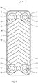
- Figs 1 and 2 disclose a plate heat exchanger 1.
- the plate heat exchanger 1 comprises a plurality of plates 2, 3, 4 arranged beside each other to form a plate package 5 of the plate heat exchanger 1.
- the plates 2, 3, 3 of the plate package 5 may be permanently joined to each other, for instance by means of a brazing material and through a brazing process.
- Each of the plates 2, 3, 4 extends in parallel with a respective extension plane p.
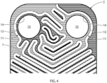
- Each of the plates 2, 3, 4, see Fig 3 comprises a central area 6 extending in parallel with the extension plane p of the plate 2, 3, 4.
- the central area 6 comprises or consists of a corrugation 7 of ridges and valleys.
- the corrugation 7 extends between an upper level p' at a distance from the main extension plane p and a lower level p" at a distance from and on an opposite side of the main extension plane p so that the ridges extend to the upper level p' and the valleys to the lower level p".
- the plates 2, 3 are stacked onto each other in the plate packages to form first plate interspaces 8 for a first medium and second plate interspaces 9 for a second medium.
- the first and second plate interspaces 8 and 9 are arranged in an alternating order in the plate package 5, as is illustrated in Fig 2 .
- Each of the plates 2, 3, 4 comprises an edge area 10 which extend around and encloses the central area 6.
- the edge area 10 may adjoin the central area 6.
- the edge area 10 may consist of or may comprise a flange sloping in relation to the extension plane p, see Fig 2 .
- Each of the plates 2, 3, 4 comprises four porthole areas 11 are provided inside the edge area 10, and preferably in a respective corner area of the plate 2, 3, 4, see Fig 3 .
- the porthole areas 11 may be located on the central area 6.
- Each of the porthole areas 11 comprises an annular flat area 12.
- the annular flat area 12 is located at one of the upper level p' and the lower level p". In the embodiments disclosed, two of the annular flat areas 12 are located at the upper level p' and the two other annular flat areas 12 are located at the lower level p".
- the plates 2, 3, 4 comprise heat exchanger plates 2, a first end plate 3 provided outside and adjoining an outermost one of the heat exchanger plates 2 in the plate package 5, and a second end plate 4 provided outside and adjoining the first end plate 3 in the plate package 5, as can be seen in Fig 2 .
- each of the heat exchanger plates 2 comprises four portholes 13 extending through a respective one of the porthole areas 11.
- Each of the portholes 13 of the heat exchanger plates 2 is defined by a porthole edge 14 formed by the annular flat area 12.
- the portholes 13 of the heat exchanger plates 2 form four porthole channels 14-17, which may form a first inlet porthole 14 for the first medium to the first plate interspaces 8, a first outlet porthole 15 for the first medium from the first plate interspaces 8, a second inlet porthole 16 for the second medium to the second plate interspaces 8, and a second outlet porthole 17 for the second medium from the second plate interspaces 8.
- the outermost heat exchanger plate 2 located on the side of the plate package 5 being opposite to the first and second end plates 3, 4 may form an outermost frame plate for attachment of conduits enabling communication with the porthole channels 14-17 for the first and second media.
- each of the heat exchanger plates 2 are identical.
- every second heat exchanger plate 2 may be rotated 180° in the extension plane p. Consequently, every second heat exchanger plate 2 may have two annular flat areas 12 located at the lower level p" and adjoining a respective annular flat area 12 located at the upper level p' on the adjacent heat exchanger plate 2, provided that there is an adjacent heat exchanger plate 2.
- Said every second heat exchanger plate 2 also has two annular flat areas 12 located at the upper level p' and adjoining a respective annular flat area 12 on the adjacent heat exchanger plate 2, provided that there is an adjacent heat exchanger plate 2.
- the first and second end plates 3, 4 are identical to The first and second end plates 3, 4
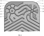
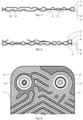
- the four porthole areas 11 of the first end plate 3 form two annular flat areas 12 located at the upper level p' and adjoining a respective annular flat area 12 located at the lower level p" on the adjacent heat exchanger plate 2, and two annular flat areas 12 located at the lower level p" and adjoining a respective annular flat area 12 located at the upper level p' on the second end plate 4, see Figs 5 and 7 .
- annular flat area 12 at the upper level p' is disclosed to the right and one annular flat area 12 at the lower level p" to the left.
- Each of the porthole areas 11 of the first end plate 3 and of the second end plate 4 is closed by means of a plate portion 20 surrounded by the annular flat area 12.
- the plate portion 20 may be circular, or may at least have a circular outer contour adjoining the annular flat area 12.
- the plate portion 20 may be a portion of the plate, for instance metal plate, forming the starting plate that is formed to the plates 2, 3, 4 by a pressing operation method. In the heat exchanger plates 2, the plate portions 20 have been removed by means of a cutting operation.
- the plate portion 20 may have a strengthening area 21 located at the lower level p" when the annular flat area 12 is located at the upper level p', and at upper level p' when the annular flat area is located at the lower level p".
- the strengthening area 21 may have a flat extension at the upper level p' and the lower level p", respectively.
- the strengthening area 21 may be annular.
- each of the porthole areas 11 of the first end plate 3 comprises a number of protrusions 22 arranged on and projecting from the annular flat area 12 to one of the lower level p" and the upper level p'.
- the protrusions 22 may project to the lower level p" when the annular flat area 12 is located at the upper level p', and to upper level p' when the annular flat area 12 is located at the lower level p".
- Each of the protrusions 22 of the first end plate 3, that project to the upper level p', to the left in Fig 5 abuts the annular flat area 12 of the adjoining outermost heat exchanger plate 2.
- each of the porthole areas 11 of the second end plate 4 also may comprise a number of protrusions 22 arranged on and projecting from the annular flat area 12 to one of the lower level p" and the upper level p'.
- the protrusions 22 may project to the lower level p" when the annular flat area 12 is located at the upper level p', and to upper level p' when the annular flat area 12 is located at the lower level p".
- Each of the protrusions 22 of the second end plate 4, that project to the upper level p', to the left in Fig 5 may abut a respective one of the protrusions 22 of the annular flat area 12 of the adjoining first end plate 3.
- Fig 5 and 7 may thus illustrate both first end plate 3 and the second end plate 4. It should be noted that the first end plate 3 and the second end plate 4 are rotated 180° in relation to each other in the extension plane p in the plate package 5.
- the protrusions 22 extend to the plate portion 20.
- the protrusions 22 may extend across the annular flat area 12, and may form beams across the annular flat area 12, for instance along a radial direction with respect to a central point of the porthole area 11. Between the protrusions 22, the annular flat area 12 may adjoin the plate portion 20.
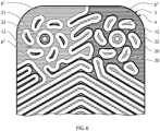
- Fig 6 refers to a second embodiment of the first end plate 3 and the second end plate 4, which differs from the first embodiment in that the protrusions 22 are located on the annular flat area 12 at a distance from the plate portion 20.
- the protrusions 22 may form isolated protrusions or islands on the annular flat are 12.
- the annular flat area 12 may thus adjoin the plate portion 20 along the whole circumferential length of the annular flat area, as is illustrated in Fig 6 .
- a third embodiment of the invention differs from the first and second embodiment in that the second end plate 4 is dispensed with.
- the plate heat exchanger 1 thus comprises a plate package 5 with the heat exchanger plates 2 and the first end plate 3 forming the outer end plate of the plate package 5.
- the porthole channels 14-17 are thus closed by a respective plate portion 20 of the first end plate 3. No media may flow through the plate interspace between the first end plate 3 and the outermost heat exchanger plate 2.
- the plate heat exchanger according to the first and second embodiments may be manufactured as explained below.
- a plurality of plates 2, 3, 4, such as plane metal plates, are provided.
- the plurality of plates 2, 3, 4 may be pressed in a first pressing operation to produce a plurality of plates 2, 3, 4, wherein each of the plates 2, 3, 4 comprises a central area 6, an edge area 10 and four porthole areas 11.
- the central area 6 may extend in parallel with an extension plane p of the plate 2, 3, 4 and may comprise a corrugation 7 of ridges and valleys.
- the corrugation 7 may extend between an upper level p' at a distance from the main extension plane p and a lower level p" at a distance from and on an opposite side of the main extension plane p so that the ridges extend to the upper level p' and the valleys to the lower level p".
- the first pressing operation may result in the edge area 10 extending around the central area 6, and each of the four porthole areas 11 comprising an annular flat area 12, which is located at one of the upper level p' and the lower level p".
- a part of the plate 2, 3, 4 forming an intermediate plate is disclosed in Fig 9 .
- the method then comprises following step of selecting a first end plate 3, a second end plate 4 and a number of heat exchanger plates 2 from said plurality of plates 2, 3, 4.
- each porthole 13 is cut in a following cutting operation through a respective one of the porthole areas 11 of each of the heat exchanger plates 2 obtained through the first pressing operation described above and shown in Fig 9 .
- the cutting operation may be performed so that each porthole 13 is defined by a porthole edge 14 formed by the annular flat area 12.
- the intermediate plate shown in Fig 9 is pressed to create a number of protrusions 22 to project from the annular flat area 12 to one of the lower level p" and the upper level p' on each of the porthole areas 11 of the first end plate 3.
- the method then comprises the step of assembling and joining the heat exchanger plates 2, the first end plate 3 and the second end plate 4 to each other to obtain a plate package 5 having four porthole channels 14-17 extending through the respective portholes 13 of the heat exchanger plates 2 and being closed by the first end plate 3 and the second end plate 4.
- the plate heat exchanger In order to manufacture the plate heat exchanger according to the third embodiment, it may be dispensed with the second pressing operation of the second end plate 4, since only the first end plate 3 is included in the plate package 5 of the plate heat exchanger.
Claims (12)
- Echangeur de chaleur à plaques (1) comprenant une pluralité de plaques (2, 3, 4) agencées les unes à côtes des autres pour former un ensemble de plaques, chaque plaque comprenantune zone centrale (6) s'étendant parallèlement à un plan d'extension (p) de la plaque (2, 3, 4) et comprenant une ondulation (7) de crêtes et de creux, dans lequel l'ondulation (7) s'étend entre un niveau supérieur (p') à distance par rapport au plan d'extension principal (p) et un niveau inférieur (p") à distance par rapport à un côté opposé du plan d'extension principal (p) de sorte que les crêtes s'étendent vers le niveau supérieur (p') et les creux vers le niveau inférieur (p"),une zone de bord (10) s'étendant autour de la zone centrale (6), etquatre zones de hublot (11), chacune comprenant une zone plate annulaire (12), dans lequel la zone plate annulaire (12) est située au niveau d'un parmi le niveau supérieur (p') et le niveau inférieur (p"),dans lequel les plaques (2, 3, 4) comprennent des plaques d'échangeur de chaleur (2) et au moins une première plaque d'extrémité (3) fournie à l'extérieur et adjacente à une plaque la plus à l'extérieur des plaques d'échangeur de chaleur (2) dans l'ensemble de plaques (5),dans lequel chacune des plaques d'échangeur de chaleur (2) comprend quatre hublots (13) s'étendant à travers une respective des zones de hublot (11), etdans lequel chacune des zones de hublot (11) de la première plaque d'extrémité (3) est fermée au moyen d'une section de plaque (20) entourée par la zone plate annulaire (12), chacune des zones de hublot (11) de la première plaque d'extrémité (3) comprend un certain nombre de saillies (22) agencées sur et faisant saillie à partir de la zone plate annulaire (12) vers l'un parmi le niveau inférieur (p") et le niveau supérieur (p'),caractérisé en ce quechaque hublot (13) des plaques d'échangeur de chaleur (2) est défini par un bord de hublot (14) formé par la zone plate annulaire (12), etchacune des saillies (22) de la première plaque d'extrémité (3), qui font saillie vers le niveau supérieur (p'), est adjacente à la zone plate annulaire (12) de la plaque d'échangeur de chaleur (2) la plus à l'extérieur adjacente, dans lequel les plaques (2, 3, 4) comprennent également une seconde plaque d'extrémité (4) fournie à l'extérieur et adjacente à la première plaque d'extrémité (3) dans l'ensemble de plaques (5), dans lequelchacune des zones de hublot (11) de la seconde plaque d'extrémité (4) est fermée au moyen d'une partie de plaque (20) entourée par la zone plate annulaire (12),chacune des zones de hublot (11) de la seconde plaque d'extrémité (4) comprend un certain nombre de saillies (22) agencées sur et faisant saillie à partir de la zone plate annulaire (12) vers l'un parmi le niveau inférieur (p") et le niveau supérieur (p'), etchacune des saillies (22) de la seconde plaque d'extrémité (4), qui font saillie vers le niveau supérieur (p'), bute contre une saillie respective des saillies (22) de la zone plate annulaire (12) de la première plaque d'extrémité adjacente (3).
- Echangeur de chaleur à plaques (1) selon la revendication 1, dans lequel les saillies (22) font saillie vers le niveau inférieur (p") lorsque la zone plate annulaire (12) est située au niveau supérieur (p'), et vers le niveau supérieur (p') lorsque la zone plate annulaire (12) est située au niveau inférieur (p").
- Echangeur de chaleur à plaques (1) selon l'une quelconque des revendications 1 et 2, dans lequel la partie de plaque qui est entourée par la zone plate annulaire est circulaire et située au niveau inférieur (p") lorsque la zone plate annulaire est située au niveau supérieur (p'), et au niveau supérieur (p') lorsque la zone plate annulaire est située au niveau inférieur (p").
- Echangeur de chaleur à plaques (1) selon la revendication 3, dans lequel les saillies (22) s'étendent vers la partie de plaque (20).
- Echangeur de chaleur à plaques (1) selon la revendication 4, dans lequel les saillies (22) s'étendent à travers la zone plate annulaire (12).
- Echangeur de chaleur à plaques (1) selon la revendication 3, dans lequel les saillies (22) sont situées sur la zone plate annulaire (12) à distance par rapport à la partie de plaque (20).
- Echangeur de chaleur à plaques (1) selon l'une quelconque des revendications 3 à 6, dans lequel la zone plate annulaire (12) est adjacente à la partie de plaque (20).
- Echangeur de chaleur à plaques (1) selon l'une quelconque des revendications 3 à 7, dans lequel la partie de plaque (20) comprend une zone de renforcement (21) qui présente une extension plate au niveau supérieur (p') et au niveau inférieur (p"), respectivement.
- Echangeur de chaleur à plaques (1) selon la revendication 8, dans lequel la zone de renforcement (21) est annulaire.
- Echangeur de chaleur à plaques (1) selon l'une quelconque des revendications précédentes, dans lequel les saillies présentent une extension plate au niveau supérieur (p') et au niveau inférieur (p"), respectivement.
- Procédé de fabrication d'un échangeur de chaleur à plaques (1), le procédé comprenant les étapes suivantes :- fournir une pluralité de plaques (2, 3, 4), et- enfoncer la pluralité de plaques (2, 3, 4) lors d'une première opération d'enfoncement pour produire une pluralité de plaques (2, 3, 4) de sorte que chaque plaque (2, 3, 4) comprendune zone centrale (6) s'étendant parallèlement à un plan d'extension (p) de la plaque (2, 3, 4) et comprenant une ondulation (7) de crêtes et de creux, dans lequel l'ondulation (7) s'étend entre un niveau supérieur (p') à distance par rapport au plan d'extension principal (p) et un niveau inférieur (p") à distance par rapport à et sur un côté opposé du plan d'extension principal (p) de sorte que les crêtes s'étendent vers le niveau supérieur (p') et les creux vers le niveau inférieur (p"),une zone de bord (10) s'étendant autour de la zone centrale (6), etquatre zones de hublot (11), chacune comprenant une zone plate annulaire (12), dans lequel la zone plate annulaire (12) est située au niveau de l'un parmi le niveau supérieur (p') et le niveau inférieur (p"),- sélectionner au moins une première plaque d'extrémité (3) et de plaques d'échangeur de chaleur (2) à partir de ladite pluralité de plaques (2, 3, 4),- découper quatre hublots (13) lors d'une opération de découpe à travers une zone respective des zones de hublot (11) de chacune des plaques d'échangeur de chaleur (2), dans lequel chaque hublot (13) est défini par un bord de hublot (14) formé par la zone plate annulaire (12),- enfoncer un certain nombre de saillies (22) lors d'une deuxième opération d'enfoncement pour faire saillie à partir de la zone plate annulaire (12) vers l'un parmi le niveau inférieur (p") et le niveau supérieur (p') sur chacune des zones de hublot (11) de la première plaque d'extrémité (3),- assembler et monter les plaques d'échangeur de chaleur (2) et de la première plaque d'extrémité (3) pour obtenir un ensemble de plaques (5) présentant quatre canaux de hublot (14-17) s'étendant à travers les hublots respectifs (13) des plaques d'échangeur de chaleur (2) et qui sont fermés par la première plaque d'extrémité (3), et- dans lequel les étapes de sélection en plus de la sélection de la première plaque d'extrémité (3) et des plaques d'échangeur de chaleur (2) comprennent également la sélection d'une seconde plaque d'extrémité (4), et dans lequel le procédé comprend l'étape supplémentaire consistant à :- enfoncer un certain nombre de saillies (22) pour faire saillie à partir de la zone plate annulaire (12) vers l'un parmi le niveau inférieur (p") et le niveau supérieur (p') sur chacune des zones de hublot (11) de la seconde plaque d'extrémité (4).
- Procédé selon la revendication 11, comprenant en outre l'étape consistant à :- assembler et monter les plaques d'échangeur de chaleur (2), la première plaque d'extrémité (3) et la seconde plaque d'extrémité (5) pour obtenir un ensemble de plaques (5) présentant quatre canaux de hublot (14-17) s'étendant à travers les hublots respectifs (13) des plaques d'échangeur de chaleur (2) et qui sont fermés par la première plaque d'extrémité (3) et la seconde plaque d'extrémité (4).
Priority Applications (1)
| Application Number | Priority Date | Filing Date | Title |
|---|---|---|---|
| SI202030171T SI3973243T1 (sl) | 2019-05-21 | 2020-05-08 | Ploščni toplotni izmenjevalnik in postopek izdelave ploščnega toplotnega izmenjevalnika |
Applications Claiming Priority (2)
| Application Number | Priority Date | Filing Date | Title |
|---|---|---|---|
| SE1950601A SE544093C2 (en) | 2019-05-21 | 2019-05-21 | Plate heat exchanger, and a method of manufacturing a plate heat exchanger |
| PCT/EP2020/062863 WO2020234006A1 (fr) | 2019-05-21 | 2020-05-08 | Échangeur de chaleur à plaques et procédé de fabrication d'un échangeur de chaleur à plaques |
Publications (2)
| Publication Number | Publication Date |
|---|---|
| EP3973243A1 EP3973243A1 (fr) | 2022-03-30 |
| EP3973243B1 true EP3973243B1 (fr) | 2023-03-01 |
Family
ID=70682840
Family Applications (1)
| Application Number | Title | Priority Date | Filing Date |
|---|---|---|---|
| EP20725687.6A Active EP3973243B1 (fr) | 2019-05-21 | 2020-05-08 | Échangeur de chaleur à plaques et procédé de fabrication d'un échangeur de chaleur à plaques |
Country Status (13)
| Country | Link |
|---|---|
| US (1) | US20220236016A1 (fr) |
| EP (1) | EP3973243B1 (fr) |
| JP (1) | JP7379539B2 (fr) |
| CN (1) | CN113825970B (fr) |
| DK (1) | DK3973243T3 (fr) |
| ES (1) | ES2942146T3 (fr) |
| FI (1) | FI3973243T3 (fr) |
| PL (1) | PL3973243T3 (fr) |
| PT (1) | PT3973243T (fr) |
| SE (1) | SE544093C2 (fr) |
| SI (1) | SI3973243T1 (fr) |
| TW (1) | TWI736265B (fr) |
| WO (1) | WO2020234006A1 (fr) |
Family Cites Families (31)
| Publication number | Priority date | Publication date | Assignee | Title |
|---|---|---|---|---|
| SE458884B (sv) * | 1987-05-29 | 1989-05-16 | Alfa Laval Thermal Ab | Permanent sammanfogad plattvaermevaexlare med sammanhaallande organ vid portarna |
| SE502984C2 (sv) * | 1993-06-17 | 1996-03-04 | Alfa Laval Thermal Ab | Plattvärmeväxlare med speciellt utformade portpartier |
| SE9700614D0 (sv) * | 1997-02-21 | 1997-02-21 | Alfa Laval Ab | Plattvärmeväxlare för tre värmeväxlande fluider |
| SE517516C2 (sv) * | 2000-10-23 | 2002-06-11 | Alfa Laval Ab | Permanent sammanfogad plattvärmeväxlare med sammanhållande organ runt porthålen |
| CA2383649C (fr) * | 2002-04-24 | 2009-08-18 | Long Manufacturing Ltd. | Plaque de scellement a couvercle inverse pour echangeur thermique |
| CA2420273A1 (fr) * | 2003-02-27 | 2004-08-27 | Peter Zurawel | Plaques d'echangeur de chaleur et methode de fabrication |
| JP4448377B2 (ja) * | 2004-05-13 | 2010-04-07 | 株式会社日阪製作所 | プレート式熱交換器 |
| CN101487671A (zh) * | 2005-04-22 | 2009-07-22 | 株式会社电装 | 热交换器 |
| SE529769E (sv) | 2006-04-04 | 2013-12-19 | Alfa Laval Corp Ab | Plattvärmeväxlare vilken innefattar åtminstone en förstärkningsplatta vilken är anordnad utanför en av de yttre värmeväxlarplattorna |
| EP1850082A1 (fr) * | 2006-04-24 | 2007-10-31 | Sundsvall Energi AB | Echangeur de chaleur |
| KR100739483B1 (ko) * | 2006-05-18 | 2007-07-16 | 성명제 | 판형 열교환기 |
| US7610949B2 (en) * | 2006-11-13 | 2009-11-03 | Dana Canada Corporation | Heat exchanger with bypass |
| EP1933105A1 (fr) * | 2006-12-11 | 2008-06-18 | Invensys APV A/S | Plaque d'échangeur thermique |
| ES2525006T3 (es) * | 2008-04-04 | 2014-12-16 | Alfa Laval Corporate Ab | Un intercambiador de calor de placas |
| ES2501541T3 (es) * | 2008-04-04 | 2014-10-02 | Alfa Laval Corporate Ab | Un intercambiador de calor de placas |
| SE533067C2 (sv) * | 2008-10-03 | 2010-06-22 | Alfa Laval Corp Ab | Plattvärmeväxlare |
| JP5298100B2 (ja) * | 2010-11-15 | 2013-09-25 | トヨタ自動車株式会社 | 車両用熱交換器 |
| DE202012102349U1 (de) * | 2011-07-14 | 2012-07-18 | Visteon Global Technologies, Inc. | Batteriekühler |
| US20140352934A1 (en) * | 2013-05-28 | 2014-12-04 | Hamilton Sundstrand Corporation | Plate heat exchanger |
| JP2015055459A (ja) * | 2013-09-13 | 2015-03-23 | 株式会社ティラド | ヘッダープレートレス熱交換器のタンク構造 |
| EP3077752B1 (fr) * | 2013-12-05 | 2020-05-13 | SWEP International AB | Échangeur de chaleur à résistance améliorée |
| CN103776284B (zh) * | 2014-02-12 | 2017-07-14 | 丹佛斯微通道换热器(嘉兴)有限公司 | 板式换热器 |
| CN103791759B (zh) * | 2014-03-07 | 2016-03-30 | 丹佛斯微通道换热器(嘉兴)有限公司 | 用于板式换热器的热交换板以及具有该热交换板的板式换热器 |
| JP6408855B2 (ja) * | 2014-10-15 | 2018-10-17 | 日本発條株式会社 | 熱交換器 |
| JP2016176618A (ja) * | 2015-03-19 | 2016-10-06 | パナソニックIpマネジメント株式会社 | 熱交換器 |
| CN205784793U (zh) * | 2016-02-04 | 2016-12-07 | 丹佛斯微通道换热器(嘉兴)有限公司 | 用于板式换热器的加强件以及板式换热器 |
| SE542049C2 (en) * | 2016-04-06 | 2020-02-18 | Alfa Laval Corp Ab | A heat exchanger plate, a plate heat exchanger, and a method of making a plate heat exchanger |
| KR101897514B1 (ko) * | 2016-04-11 | 2018-09-12 | 주식회사 엘에치이 | 판형 열교환기용 전열판 |
| JP6631409B2 (ja) * | 2016-05-23 | 2020-01-15 | 株式会社デンソー | 熱交換器 |
| CN108541182B (zh) * | 2017-03-06 | 2021-09-07 | 达纳加拿大公司 | 用于冷却电子模块的多个层的热交换器 |
| CN208382951U (zh) * | 2018-07-02 | 2019-01-15 | 宁波市哈雷换热设备有限公司 | 一种板式热交换器 |
-
2019
- 2019-05-21 SE SE1950601A patent/SE544093C2/en unknown
-
2020
- 2020-05-08 CN CN202080037325.0A patent/CN113825970B/zh active Active
- 2020-05-08 EP EP20725687.6A patent/EP3973243B1/fr active Active
- 2020-05-08 ES ES20725687T patent/ES2942146T3/es active Active
- 2020-05-08 PL PL20725687.6T patent/PL3973243T3/pl unknown
- 2020-05-08 WO PCT/EP2020/062863 patent/WO2020234006A1/fr unknown
- 2020-05-08 JP JP2021569171A patent/JP7379539B2/ja active Active
- 2020-05-08 SI SI202030171T patent/SI3973243T1/sl unknown
- 2020-05-08 US US17/612,730 patent/US20220236016A1/en active Pending
- 2020-05-08 FI FIEP20725687.6T patent/FI3973243T3/fi active
- 2020-05-08 DK DK20725687.6T patent/DK3973243T3/da active
- 2020-05-08 PT PT207256876T patent/PT3973243T/pt unknown
- 2020-05-15 TW TW109116216A patent/TWI736265B/zh active
Also Published As
| Publication number | Publication date |
|---|---|
| SE1950601A1 (en) | 2020-11-22 |
| SE544093C2 (en) | 2021-12-21 |
| US20220236016A1 (en) | 2022-07-28 |
| DK3973243T3 (da) | 2023-03-20 |
| ES2942146T3 (es) | 2023-05-30 |
| SI3973243T1 (sl) | 2023-07-31 |
| TW202100932A (zh) | 2021-01-01 |
| WO2020234006A1 (fr) | 2020-11-26 |
| EP3973243A1 (fr) | 2022-03-30 |
| JP2022534372A (ja) | 2022-07-29 |
| PL3973243T3 (pl) | 2023-04-03 |
| CN113825970B (zh) | 2023-09-05 |
| TWI736265B (zh) | 2021-08-11 |
| PT3973243T (pt) | 2023-04-11 |
| FI3973243T3 (fi) | 2023-05-15 |
| CN113825970A (zh) | 2021-12-21 |
| JP7379539B2 (ja) | 2023-11-14 |
Similar Documents
| Publication | Publication Date | Title |
|---|---|---|
| EP2084481B1 (fr) | Échangeur de chaleur à plaque | |
| EP0636239B1 (fr) | Echangeur de chaleur a plaques | |
| EP2585783B1 (fr) | Plaque d'un échangeur de chaleur et échangeur de chaleur | |
| US4431050A (en) | Stacked-plate heat exchanger made of identical corrugated plates | |
| EP2126506B1 (fr) | Échangeur thermique à plaques | |
| DK2508831T3 (en) | PLATE HEAT EXCHANGE | |
| EP2257756B1 (fr) | Échangeur de chaleur à plaques | |
| EP2002195B1 (fr) | Echangeur thermique a plaques avec des plaques de remforcement a l'exterieur des plaques d'echange thermique les plus externes | |
| US8887796B2 (en) | Plate heat exchanger | |
| EP3559581B1 (fr) | Échangeur thermique à plaques | |
| EP3973243B1 (fr) | Échangeur de chaleur à plaques et procédé de fabrication d'un échangeur de chaleur à plaques | |
| EP2815198B1 (fr) | Échangeur de chaleur à plaque présentant une résistance améliorée dans la zone d'orifice | |
| EP4103904B1 (fr) | Plaque d'échangeur de chaleur et échangeur de chaleur à plaques | |
| EP4083561B1 (fr) | Plaque et joint de transfert de chaleur | |
| CN111981877B (zh) | 板式热交换器 | |
| WO2024061824A1 (fr) | Échangeur thermique et plaque de séparation associée |
Legal Events
| Date | Code | Title | Description |
|---|---|---|---|
| STAA | Information on the status of an ep patent application or granted ep patent |
Free format text: STATUS: UNKNOWN |
|
| STAA | Information on the status of an ep patent application or granted ep patent |
Free format text: STATUS: THE INTERNATIONAL PUBLICATION HAS BEEN MADE |
|
| PUAI | Public reference made under article 153(3) epc to a published international application that has entered the european phase |
Free format text: ORIGINAL CODE: 0009012 |
|
| STAA | Information on the status of an ep patent application or granted ep patent |
Free format text: STATUS: REQUEST FOR EXAMINATION WAS MADE |
|
| 17P | Request for examination filed |
Effective date: 20211125 |
|
| AK | Designated contracting states |
Kind code of ref document: A1 Designated state(s): AL AT BE BG CH CY CZ DE DK EE ES FI FR GB GR HR HU IE IS IT LI LT LU LV MC MK MT NL NO PL PT RO RS SE SI SK SM TR |
|
| RIN1 | Information on inventor provided before grant (corrected) |
Inventor name: ROMLUND, JENS |
|
| DAV | Request for validation of the european patent (deleted) | ||
| DAX | Request for extension of the european patent (deleted) | ||
| GRAP | Despatch of communication of intention to grant a patent |
Free format text: ORIGINAL CODE: EPIDOSNIGR1 |
|
| STAA | Information on the status of an ep patent application or granted ep patent |
Free format text: STATUS: GRANT OF PATENT IS INTENDED |
|
| INTG | Intention to grant announced |
Effective date: 20221011 |
|
| RIN1 | Information on inventor provided before grant (corrected) |
Inventor name: ROMLUND, JENS |
|
| GRAS | Grant fee paid |
Free format text: ORIGINAL CODE: EPIDOSNIGR3 |
|
| GRAA | (expected) grant |
Free format text: ORIGINAL CODE: 0009210 |
|
| STAA | Information on the status of an ep patent application or granted ep patent |
Free format text: STATUS: THE PATENT HAS BEEN GRANTED |
|
| AK | Designated contracting states |
Kind code of ref document: B1 Designated state(s): AL AT BE BG CH CY CZ DE DK EE ES FI FR GB GR HR HU IE IS IT LI LT LU LV MC MK MT NL NO PL PT RO RS SE SI SK SM TR |
|
| REG | Reference to a national code |
Ref country code: GB Ref legal event code: FG4D |
|
| REG | Reference to a national code |
Ref country code: CH Ref legal event code: EP Ref country code: AT Ref legal event code: REF Ref document number: 1551234 Country of ref document: AT Kind code of ref document: T Effective date: 20230315 |
|
| REG | Reference to a national code |
Ref country code: DK Ref legal event code: T3 Effective date: 20230315 |
|
| REG | Reference to a national code |
Ref country code: DE Ref legal event code: R096 Ref document number: 602020008524 Country of ref document: DE |
|
| REG | Reference to a national code |
Ref country code: IE Ref legal event code: FG4D |
|
| REG | Reference to a national code |
Ref country code: PT Ref legal event code: SC4A Ref document number: 3973243 Country of ref document: PT Date of ref document: 20230411 Kind code of ref document: T Free format text: AVAILABILITY OF NATIONAL TRANSLATION Effective date: 20230403 |
|
| REG | Reference to a national code |
Ref country code: SK Ref legal event code: T3 Ref document number: E 41316 Country of ref document: SK |
|
| PGFP | Annual fee paid to national office [announced via postgrant information from national office to epo] |
Ref country code: FR Payment date: 20230309 Year of fee payment: 4 |
|
| REG | Reference to a national code |
Ref country code: SE Ref legal event code: TRGR |
|
| REG | Reference to a national code |
Ref country code: ES Ref legal event code: FG2A Ref document number: 2942146 Country of ref document: ES Kind code of ref document: T3 Effective date: 20230530 |
|
| PGFP | Annual fee paid to national office [announced via postgrant information from national office to epo] |
Ref country code: SK Payment date: 20230324 Year of fee payment: 4 |
|
| REG | Reference to a national code |
Ref country code: NL Ref legal event code: FP |
|
| P01 | Opt-out of the competence of the unified patent court (upc) registered |
Effective date: 20230421 |
|
| REG | Reference to a national code |
Ref country code: LT Ref legal event code: MG9D |
|
| PGFP | Annual fee paid to national office [announced via postgrant information from national office to epo] |
Ref country code: NL Payment date: 20230314 Year of fee payment: 4 |
|
| REG | Reference to a national code |
Ref country code: GR Ref legal event code: EP Ref document number: 20230400769 Country of ref document: GR Effective date: 20230710 |
|
| PG25 | Lapsed in a contracting state [announced via postgrant information from national office to epo] |
Ref country code: RS Free format text: LAPSE BECAUSE OF FAILURE TO SUBMIT A TRANSLATION OF THE DESCRIPTION OR TO PAY THE FEE WITHIN THE PRESCRIBED TIME-LIMIT Effective date: 20230301 Ref country code: NO Free format text: LAPSE BECAUSE OF FAILURE TO SUBMIT A TRANSLATION OF THE DESCRIPTION OR TO PAY THE FEE WITHIN THE PRESCRIBED TIME-LIMIT Effective date: 20230601 Ref country code: LV Free format text: LAPSE BECAUSE OF FAILURE TO SUBMIT A TRANSLATION OF THE DESCRIPTION OR TO PAY THE FEE WITHIN THE PRESCRIBED TIME-LIMIT Effective date: 20230301 Ref country code: LT Free format text: LAPSE BECAUSE OF FAILURE TO SUBMIT A TRANSLATION OF THE DESCRIPTION OR TO PAY THE FEE WITHIN THE PRESCRIBED TIME-LIMIT Effective date: 20230301 Ref country code: HR Free format text: LAPSE BECAUSE OF FAILURE TO SUBMIT A TRANSLATION OF THE DESCRIPTION OR TO PAY THE FEE WITHIN THE PRESCRIBED TIME-LIMIT Effective date: 20230301 |
|
| PGFP | Annual fee paid to national office [announced via postgrant information from national office to epo] |
Ref country code: PT Payment date: 20230502 Year of fee payment: 4 Ref country code: IT Payment date: 20230531 Year of fee payment: 4 Ref country code: ES Payment date: 20230605 Year of fee payment: 4 Ref country code: DK Payment date: 20230511 Year of fee payment: 4 Ref country code: DE Payment date: 20230314 Year of fee payment: 4 Ref country code: CZ Payment date: 20230419 Year of fee payment: 4 |
|
| PGFP | Annual fee paid to national office [announced via postgrant information from national office to epo] |
Ref country code: TR Payment date: 20230505 Year of fee payment: 4 Ref country code: SI Payment date: 20230323 Year of fee payment: 4 Ref country code: PL Payment date: 20230315 Year of fee payment: 4 Ref country code: GR Payment date: 20230602 Year of fee payment: 4 Ref country code: FI Payment date: 20230513 Year of fee payment: 4 |
|
| PGFP | Annual fee paid to national office [announced via postgrant information from national office to epo] |
Ref country code: BE Payment date: 20230418 Year of fee payment: 4 |
|
| PG25 | Lapsed in a contracting state [announced via postgrant information from national office to epo] |
Ref country code: SM Free format text: LAPSE BECAUSE OF FAILURE TO SUBMIT A TRANSLATION OF THE DESCRIPTION OR TO PAY THE FEE WITHIN THE PRESCRIBED TIME-LIMIT Effective date: 20230301 Ref country code: RO Free format text: LAPSE BECAUSE OF FAILURE TO SUBMIT A TRANSLATION OF THE DESCRIPTION OR TO PAY THE FEE WITHIN THE PRESCRIBED TIME-LIMIT Effective date: 20230301 Ref country code: EE Free format text: LAPSE BECAUSE OF FAILURE TO SUBMIT A TRANSLATION OF THE DESCRIPTION OR TO PAY THE FEE WITHIN THE PRESCRIBED TIME-LIMIT Effective date: 20230301 |
|
| PG25 | Lapsed in a contracting state [announced via postgrant information from national office to epo] |
Ref country code: IS Free format text: LAPSE BECAUSE OF FAILURE TO SUBMIT A TRANSLATION OF THE DESCRIPTION OR TO PAY THE FEE WITHIN THE PRESCRIBED TIME-LIMIT Effective date: 20230701 |
|
| PGFP | Annual fee paid to national office [announced via postgrant information from national office to epo] |
Ref country code: SE Payment date: 20230310 Year of fee payment: 4 |
|
| REG | Reference to a national code |
Ref country code: DE Ref legal event code: R097 Ref document number: 602020008524 Country of ref document: DE |
|
| REG | Reference to a national code |
Ref country code: CH Ref legal event code: PL |
|
| PLBE | No opposition filed within time limit |
Free format text: ORIGINAL CODE: 0009261 |
|
| STAA | Information on the status of an ep patent application or granted ep patent |
Free format text: STATUS: NO OPPOSITION FILED WITHIN TIME LIMIT |
|
| PG25 | Lapsed in a contracting state [announced via postgrant information from national office to epo] |
Ref country code: MC Free format text: LAPSE BECAUSE OF FAILURE TO SUBMIT A TRANSLATION OF THE DESCRIPTION OR TO PAY THE FEE WITHIN THE PRESCRIBED TIME-LIMIT Effective date: 20230301 |
|
| PG25 | Lapsed in a contracting state [announced via postgrant information from national office to epo] |
Ref country code: MC Free format text: LAPSE BECAUSE OF FAILURE TO SUBMIT A TRANSLATION OF THE DESCRIPTION OR TO PAY THE FEE WITHIN THE PRESCRIBED TIME-LIMIT Effective date: 20230301 Ref country code: LU Free format text: LAPSE BECAUSE OF NON-PAYMENT OF DUE FEES Effective date: 20230508 Ref country code: LI Free format text: LAPSE BECAUSE OF NON-PAYMENT OF DUE FEES Effective date: 20230531 Ref country code: CH Free format text: LAPSE BECAUSE OF NON-PAYMENT OF DUE FEES Effective date: 20230531 |
|
| 26N | No opposition filed |
Effective date: 20231204 |
|
| REG | Reference to a national code |
Ref country code: IE Ref legal event code: MM4A |
|
| PG25 | Lapsed in a contracting state [announced via postgrant information from national office to epo] |
Ref country code: IE Free format text: LAPSE BECAUSE OF NON-PAYMENT OF DUE FEES Effective date: 20230508 |
|
| PGFP | Annual fee paid to national office [announced via postgrant information from national office to epo] |
Ref country code: NL Payment date: 20240315 Year of fee payment: 5 |