EP3973133B1 - Micro-cellular foam weather seal - Google Patents
Micro-cellular foam weather seal Download PDFInfo
- Publication number
- EP3973133B1 EP3973133B1 EP20768225.3A EP20768225A EP3973133B1 EP 3973133 B1 EP3973133 B1 EP 3973133B1 EP 20768225 A EP20768225 A EP 20768225A EP 3973133 B1 EP3973133 B1 EP 3973133B1
- Authority
- EP
- European Patent Office
- Prior art keywords
- weather seal
- weather
- foam
- micro
- bulb
- Prior art date
- Legal status (The legal status is an assumption and is not a legal conclusion. Google has not performed a legal analysis and makes no representation as to the accuracy of the status listed.)
- Active
Links
Images





Classifications
-
- E—FIXED CONSTRUCTIONS
- E06—DOORS, WINDOWS, SHUTTERS, OR ROLLER BLINDS IN GENERAL; LADDERS
- E06B—FIXED OR MOVABLE CLOSURES FOR OPENINGS IN BUILDINGS, VEHICLES, FENCES OR LIKE ENCLOSURES IN GENERAL, e.g. DOORS, WINDOWS, BLINDS, GATES
- E06B7/00—Special arrangements or measures in connection with doors or windows
- E06B7/16—Sealing arrangements on wings or parts co-operating with the wings
- E06B7/22—Sealing arrangements on wings or parts co-operating with the wings by means of elastic edgings, e.g. elastic rubber tubes; by means of resilient edgings, e.g. felt or plush strips, resilient metal strips
- E06B7/23—Plastic, sponge rubber, or like strips or tubes
- E06B7/2314—Plastic, sponge rubber, or like strips or tubes characterised by the material
-
- B—PERFORMING OPERATIONS; TRANSPORTING
- B29—WORKING OF PLASTICS; WORKING OF SUBSTANCES IN A PLASTIC STATE IN GENERAL
- B29C—SHAPING OR JOINING OF PLASTICS; SHAPING OF MATERIAL IN A PLASTIC STATE, NOT OTHERWISE PROVIDED FOR; AFTER-TREATMENT OF THE SHAPED PRODUCTS, e.g. REPAIRING
- B29C44/00—Shaping by internal pressure generated in the material, e.g. swelling or foaming ; Producing porous or cellular expanded plastics articles
- B29C44/20—Shaping by internal pressure generated in the material, e.g. swelling or foaming ; Producing porous or cellular expanded plastics articles for articles of indefinite length
- B29C44/22—Shaping by internal pressure generated in the material, e.g. swelling or foaming ; Producing porous or cellular expanded plastics articles for articles of indefinite length consisting of at least two parts of chemically or physically different materials, e.g. having different densities
-
- B—PERFORMING OPERATIONS; TRANSPORTING
- B29—WORKING OF PLASTICS; WORKING OF SUBSTANCES IN A PLASTIC STATE IN GENERAL
- B29C—SHAPING OR JOINING OF PLASTICS; SHAPING OF MATERIAL IN A PLASTIC STATE, NOT OTHERWISE PROVIDED FOR; AFTER-TREATMENT OF THE SHAPED PRODUCTS, e.g. REPAIRING
- B29C44/00—Shaping by internal pressure generated in the material, e.g. swelling or foaming ; Producing porous or cellular expanded plastics articles
- B29C44/34—Auxiliary operations
- B29C44/36—Feeding the material to be shaped
- B29C44/46—Feeding the material to be shaped into an open space or onto moving surfaces, i.e. to make articles of indefinite length
- B29C44/50—Feeding the material to be shaped into an open space or onto moving surfaces, i.e. to make articles of indefinite length using pressure difference, e.g. by extrusion or by spraying
-
- B—PERFORMING OPERATIONS; TRANSPORTING
- B29—WORKING OF PLASTICS; WORKING OF SUBSTANCES IN A PLASTIC STATE IN GENERAL
- B29C—SHAPING OR JOINING OF PLASTICS; SHAPING OF MATERIAL IN A PLASTIC STATE, NOT OTHERWISE PROVIDED FOR; AFTER-TREATMENT OF THE SHAPED PRODUCTS, e.g. REPAIRING
- B29C44/00—Shaping by internal pressure generated in the material, e.g. swelling or foaming ; Producing porous or cellular expanded plastics articles
- B29C44/34—Auxiliary operations
- B29C44/56—After-treatment of articles, e.g. for altering the shape
- B29C44/5627—After-treatment of articles, e.g. for altering the shape by mechanical deformation, e.g. crushing, embossing, stretching
-
- B—PERFORMING OPERATIONS; TRANSPORTING
- B29—WORKING OF PLASTICS; WORKING OF SUBSTANCES IN A PLASTIC STATE IN GENERAL
- B29C—SHAPING OR JOINING OF PLASTICS; SHAPING OF MATERIAL IN A PLASTIC STATE, NOT OTHERWISE PROVIDED FOR; AFTER-TREATMENT OF THE SHAPED PRODUCTS, e.g. REPAIRING
- B29C44/00—Shaping by internal pressure generated in the material, e.g. swelling or foaming ; Producing porous or cellular expanded plastics articles
- B29C44/34—Auxiliary operations
- B29C44/56—After-treatment of articles, e.g. for altering the shape
- B29C44/5681—Covering the foamed object with, e.g. a lining
-
- B—PERFORMING OPERATIONS; TRANSPORTING
- B29—WORKING OF PLASTICS; WORKING OF SUBSTANCES IN A PLASTIC STATE IN GENERAL
- B29C—SHAPING OR JOINING OF PLASTICS; SHAPING OF MATERIAL IN A PLASTIC STATE, NOT OTHERWISE PROVIDED FOR; AFTER-TREATMENT OF THE SHAPED PRODUCTS, e.g. REPAIRING
- B29C44/00—Shaping by internal pressure generated in the material, e.g. swelling or foaming ; Producing porous or cellular expanded plastics articles
- B29C44/34—Auxiliary operations
- B29C44/60—Measuring, controlling or regulating
- B29C44/605—Calibration following a shaping operation, e.g. extrusion
-
- B—PERFORMING OPERATIONS; TRANSPORTING
- B29—WORKING OF PLASTICS; WORKING OF SUBSTANCES IN A PLASTIC STATE IN GENERAL
- B29C—SHAPING OR JOINING OF PLASTICS; SHAPING OF MATERIAL IN A PLASTIC STATE, NOT OTHERWISE PROVIDED FOR; AFTER-TREATMENT OF THE SHAPED PRODUCTS, e.g. REPAIRING
- B29C48/00—Extrusion moulding, i.e. expressing the moulding material through a die or nozzle which imparts the desired form; Apparatus therefor
- B29C48/001—Combinations of extrusion moulding with other shaping operations
- B29C48/0012—Combinations of extrusion moulding with other shaping operations combined with shaping by internal pressure generated in the material, e.g. foaming
-
- B—PERFORMING OPERATIONS; TRANSPORTING
- B29—WORKING OF PLASTICS; WORKING OF SUBSTANCES IN A PLASTIC STATE IN GENERAL
- B29C—SHAPING OR JOINING OF PLASTICS; SHAPING OF MATERIAL IN A PLASTIC STATE, NOT OTHERWISE PROVIDED FOR; AFTER-TREATMENT OF THE SHAPED PRODUCTS, e.g. REPAIRING
- B29C48/00—Extrusion moulding, i.e. expressing the moulding material through a die or nozzle which imparts the desired form; Apparatus therefor
- B29C48/03—Extrusion moulding, i.e. expressing the moulding material through a die or nozzle which imparts the desired form; Apparatus therefor characterised by the shape of the extruded material at extrusion
- B29C48/12—Articles with an irregular circumference when viewed in cross-section, e.g. window profiles
-
- B—PERFORMING OPERATIONS; TRANSPORTING
- B29—WORKING OF PLASTICS; WORKING OF SUBSTANCES IN A PLASTIC STATE IN GENERAL
- B29C—SHAPING OR JOINING OF PLASTICS; SHAPING OF MATERIAL IN A PLASTIC STATE, NOT OTHERWISE PROVIDED FOR; AFTER-TREATMENT OF THE SHAPED PRODUCTS, e.g. REPAIRING
- B29C48/00—Extrusion moulding, i.e. expressing the moulding material through a die or nozzle which imparts the desired form; Apparatus therefor
- B29C48/25—Component parts, details or accessories; Auxiliary operations
- B29C48/36—Means for plasticising or homogenising the moulding material or forcing it through the nozzle or die
- B29C48/49—Means for plasticising or homogenising the moulding material or forcing it through the nozzle or die using two or more extruders to feed one die or nozzle
-
- B—PERFORMING OPERATIONS; TRANSPORTING
- B29—WORKING OF PLASTICS; WORKING OF SUBSTANCES IN A PLASTIC STATE IN GENERAL
- B29C—SHAPING OR JOINING OF PLASTICS; SHAPING OF MATERIAL IN A PLASTIC STATE, NOT OTHERWISE PROVIDED FOR; AFTER-TREATMENT OF THE SHAPED PRODUCTS, e.g. REPAIRING
- B29C48/00—Extrusion moulding, i.e. expressing the moulding material through a die or nozzle which imparts the desired form; Apparatus therefor
- B29C48/25—Component parts, details or accessories; Auxiliary operations
- B29C48/88—Thermal treatment of the stream of extruded material, e.g. cooling
- B29C48/90—Thermal treatment of the stream of extruded material, e.g. cooling with calibration or sizing, i.e. combined with fixing or setting of the final dimensions of the extruded article
- B29C48/905—Thermal treatment of the stream of extruded material, e.g. cooling with calibration or sizing, i.e. combined with fixing or setting of the final dimensions of the extruded article using wet calibration, i.e. in a quenching tank
-
- E—FIXED CONSTRUCTIONS
- E06—DOORS, WINDOWS, SHUTTERS, OR ROLLER BLINDS IN GENERAL; LADDERS
- E06B—FIXED OR MOVABLE CLOSURES FOR OPENINGS IN BUILDINGS, VEHICLES, FENCES OR LIKE ENCLOSURES IN GENERAL, e.g. DOORS, WINDOWS, BLINDS, GATES
- E06B7/00—Special arrangements or measures in connection with doors or windows
- E06B7/16—Sealing arrangements on wings or parts co-operating with the wings
- E06B7/22—Sealing arrangements on wings or parts co-operating with the wings by means of elastic edgings, e.g. elastic rubber tubes; by means of resilient edgings, e.g. felt or plush strips, resilient metal strips
- E06B7/23—Plastic, sponge rubber, or like strips or tubes
- E06B7/2305—Plastic, sponge rubber, or like strips or tubes with an integrally formed part for fixing the edging
- E06B7/2307—Plastic, sponge rubber, or like strips or tubes with an integrally formed part for fixing the edging with a single sealing-line or -plane between the wing and the part co-operating with the wing
- E06B7/2309—Plastic, sponge rubber, or like strips or tubes with an integrally formed part for fixing the edging with a single sealing-line or -plane between the wing and the part co-operating with the wing with a hollow sealing part
-
- E—FIXED CONSTRUCTIONS
- E06—DOORS, WINDOWS, SHUTTERS, OR ROLLER BLINDS IN GENERAL; LADDERS
- E06B—FIXED OR MOVABLE CLOSURES FOR OPENINGS IN BUILDINGS, VEHICLES, FENCES OR LIKE ENCLOSURES IN GENERAL, e.g. DOORS, WINDOWS, BLINDS, GATES
- E06B7/00—Special arrangements or measures in connection with doors or windows
- E06B7/16—Sealing arrangements on wings or parts co-operating with the wings
- E06B7/22—Sealing arrangements on wings or parts co-operating with the wings by means of elastic edgings, e.g. elastic rubber tubes; by means of resilient edgings, e.g. felt or plush strips, resilient metal strips
- E06B7/23—Plastic, sponge rubber, or like strips or tubes
- E06B7/2305—Plastic, sponge rubber, or like strips or tubes with an integrally formed part for fixing the edging
- E06B7/2312—Plastic, sponge rubber, or like strips or tubes with an integrally formed part for fixing the edging with two or more sealing-lines or -planes between the wing and part co-operating with the wing
-
- B—PERFORMING OPERATIONS; TRANSPORTING
- B29—WORKING OF PLASTICS; WORKING OF SUBSTANCES IN A PLASTIC STATE IN GENERAL
- B29C—SHAPING OR JOINING OF PLASTICS; SHAPING OF MATERIAL IN A PLASTIC STATE, NOT OTHERWISE PROVIDED FOR; AFTER-TREATMENT OF THE SHAPED PRODUCTS, e.g. REPAIRING
- B29C2948/00—Indexing scheme relating to extrusion moulding
- B29C2948/92—Measuring, controlling or regulating
-
- B—PERFORMING OPERATIONS; TRANSPORTING
- B29—WORKING OF PLASTICS; WORKING OF SUBSTANCES IN A PLASTIC STATE IN GENERAL
- B29C—SHAPING OR JOINING OF PLASTICS; SHAPING OF MATERIAL IN A PLASTIC STATE, NOT OTHERWISE PROVIDED FOR; AFTER-TREATMENT OF THE SHAPED PRODUCTS, e.g. REPAIRING
- B29C2948/00—Indexing scheme relating to extrusion moulding
- B29C2948/92—Measuring, controlling or regulating
- B29C2948/92323—Location or phase of measurement
- B29C2948/92428—Calibration, after-treatment, or cooling zone
-
- B—PERFORMING OPERATIONS; TRANSPORTING
- B29—WORKING OF PLASTICS; WORKING OF SUBSTANCES IN A PLASTIC STATE IN GENERAL
- B29C—SHAPING OR JOINING OF PLASTICS; SHAPING OF MATERIAL IN A PLASTIC STATE, NOT OTHERWISE PROVIDED FOR; AFTER-TREATMENT OF THE SHAPED PRODUCTS, e.g. REPAIRING
- B29C2948/00—Indexing scheme relating to extrusion moulding
- B29C2948/92—Measuring, controlling or regulating
- B29C2948/92504—Controlled parameter
- B29C2948/9258—Velocity
-
- B—PERFORMING OPERATIONS; TRANSPORTING
- B29—WORKING OF PLASTICS; WORKING OF SUBSTANCES IN A PLASTIC STATE IN GENERAL
- B29C—SHAPING OR JOINING OF PLASTICS; SHAPING OF MATERIAL IN A PLASTIC STATE, NOT OTHERWISE PROVIDED FOR; AFTER-TREATMENT OF THE SHAPED PRODUCTS, e.g. REPAIRING
- B29C2948/00—Indexing scheme relating to extrusion moulding
- B29C2948/92—Measuring, controlling or regulating
- B29C2948/92504—Controlled parameter
- B29C2948/9258—Velocity
- B29C2948/926—Flow or feed rate
-
- B—PERFORMING OPERATIONS; TRANSPORTING
- B29—WORKING OF PLASTICS; WORKING OF SUBSTANCES IN A PLASTIC STATE IN GENERAL
- B29C—SHAPING OR JOINING OF PLASTICS; SHAPING OF MATERIAL IN A PLASTIC STATE, NOT OTHERWISE PROVIDED FOR; AFTER-TREATMENT OF THE SHAPED PRODUCTS, e.g. REPAIRING
- B29C2948/00—Indexing scheme relating to extrusion moulding
- B29C2948/92—Measuring, controlling or regulating
- B29C2948/92819—Location or phase of control
- B29C2948/92923—Calibration, after-treatment or cooling zone
-
- B—PERFORMING OPERATIONS; TRANSPORTING
- B29—WORKING OF PLASTICS; WORKING OF SUBSTANCES IN A PLASTIC STATE IN GENERAL
- B29D—PRODUCING PARTICULAR ARTICLES FROM PLASTICS OR FROM SUBSTANCES IN A PLASTIC STATE
- B29D99/00—Subject matter not provided for in other groups of this subclass
- B29D99/0053—Producing sealings
-
- B—PERFORMING OPERATIONS; TRANSPORTING
- B29—WORKING OF PLASTICS; WORKING OF SUBSTANCES IN A PLASTIC STATE IN GENERAL
- B29K—INDEXING SCHEME ASSOCIATED WITH SUBCLASSES B29B, B29C OR B29D, RELATING TO MOULDING MATERIALS OR TO MATERIALS FOR MOULDS, REINFORCEMENTS, FILLERS OR PREFORMED PARTS, e.g. INSERTS
- B29K2021/00—Use of unspecified rubbers as moulding material
- B29K2021/003—Thermoplastic elastomers
-
- B—PERFORMING OPERATIONS; TRANSPORTING
- B29—WORKING OF PLASTICS; WORKING OF SUBSTANCES IN A PLASTIC STATE IN GENERAL
- B29K—INDEXING SCHEME ASSOCIATED WITH SUBCLASSES B29B, B29C OR B29D, RELATING TO MOULDING MATERIALS OR TO MATERIALS FOR MOULDS, REINFORCEMENTS, FILLERS OR PREFORMED PARTS, e.g. INSERTS
- B29K2023/00—Use of polyalkenes or derivatives thereof as moulding material
- B29K2023/10—Polymers of propylene
- B29K2023/12—PP, i.e. polypropylene
-
- B—PERFORMING OPERATIONS; TRANSPORTING
- B29—WORKING OF PLASTICS; WORKING OF SUBSTANCES IN A PLASTIC STATE IN GENERAL
- B29K—INDEXING SCHEME ASSOCIATED WITH SUBCLASSES B29B, B29C OR B29D, RELATING TO MOULDING MATERIALS OR TO MATERIALS FOR MOULDS, REINFORCEMENTS, FILLERS OR PREFORMED PARTS, e.g. INSERTS
- B29K2105/00—Condition, form or state of moulded material or of the material to be shaped
- B29K2105/04—Condition, form or state of moulded material or of the material to be shaped cellular or porous
-
- B—PERFORMING OPERATIONS; TRANSPORTING
- B29—WORKING OF PLASTICS; WORKING OF SUBSTANCES IN A PLASTIC STATE IN GENERAL
- B29L—INDEXING SCHEME ASSOCIATED WITH SUBCLASS B29C, RELATING TO PARTICULAR ARTICLES
- B29L2031/00—Other particular articles
- B29L2031/26—Sealing devices, e.g. packaging for pistons or pipe joints
-
- B—PERFORMING OPERATIONS; TRANSPORTING
- B29—WORKING OF PLASTICS; WORKING OF SUBSTANCES IN A PLASTIC STATE IN GENERAL
- B29L—INDEXING SCHEME ASSOCIATED WITH SUBCLASS B29C, RELATING TO PARTICULAR ARTICLES
- B29L2031/00—Other particular articles
- B29L2031/26—Sealing devices, e.g. packaging for pistons or pipe joints
- B29L2031/265—Packings, Gaskets
Definitions
- the present disclosure is directed generally to weather seals used on windows and doors.
- Weather seals or weather-strips are commonly attached to the edges of doors and windows to decrease or prevent air from permeating between the interior and exterior of the door or window. Weather seals are also used to seal between the moving components of a window and door. Most typically weather seals are composed of thermoplastic elastomers or EPDM rubber, wrapped urethane foam or other flexible thermoset materials. These materials provide flexibility, resiliency, durability, and generally have low coefficients of friction and provide a consistent low closing force. Minimizing the loss of functional height of the weather seal over the life of the window or door is very important. Examples of weather seals are known e.g. from DE 20 2004 003637 U1 and US 2003/157316 A1 .
- More advanced weather seals feature multiple bulbs and sealing flaps that extend the reach of a bulb seal.
- Some advanced or higher performance weatherseals have a solid foam center made from urethane foam or a TPE water blown foam. In some cases a hollow foam may be used to reduce closing forces.
- the materials and processing methods used to make foam filled seals are complex, expensive and require multiple steps.
- Urethane seals are not recyclable and utilize a two-part chemistry process that requires special handling methods.
- the two advanced weathers seals described above will use at least three different materials requiring three extruders and if they add a slip coating to reduce friction, a fourth extruder is required. This results in an expensive process that takes up a considerable amount of space. These processes also require highly skilled workers due to the complexity of the processes used.
- the present invention is directed to a micro-cellular foam weather seal as defined in claim 1 and to a method as defined in claim 6 for manufacturing the seal.
- a weather seal for use on a weather permeable barrier separating the indoor from the outdoor, comprising: an elongated, compressible micro-cellular foam bulb adapted for connection to the barrier; and an elongated, compressible micro-cellular foam element extending along the length of the foam bulb, wherein the foam element is spaced from the barrier.
- the weather seal further comprises a silicone slip agent incorporated therein.
- the weather seal further comprises a polypropylene member attached to and extending the length of the foam bulb and to which the foam element is attached.
- the polypropylene member comprises an elongated spine having opposing surfaces and the foam element comprises at least one barb extending off of each surface of the spine.
- the weather seal further comprises a pair of sealing flaps that extend diagonally upward from the top of bulb, opposite the spine.
- the foam bulb is of a first predetermined diameter and the foam element comprises a bulb-shape and is of a second diameter smaller than the first diameter.
- the foam bulb is tear-drop shaped and or a predetermined length and the foam element is of a bulb-shape having a diameter that is smaller in dimension than the predetermined length.
- the bulb has hardness in the range of 10 to 75 durometer on a shore A scale and the foam element has a hardness in the range of 10 to 75 durometer on a shore A scale.
- a method for manufacturing a micro-cellular foam weather seal for use on a weather permeable barrier separating the indoor from the outdoor and having an elongated, compressible micro-cellular foam bulb adapted for connection to the barrier and an elongated, compressible micro-cellular foam element extending along the length of the foam bulb, wherein the foam element is spaced from the barrier, wherein the weather seal further comprises a polypropylene member attached to and extending the length of the foam bulb and to which the foam element is attached, the method comprising the steps of: delivering the micro-cellular foam material from a storage cell to a weigh scale blender and then to a drier; delivering the micro-cellular foam material from the drier to a main extruder; delivering a polypropylene material from a storage cell to a first co-extruder; pulling the micro-cellular foam material and the polypropylene material from through the main extruder and first co-extruder, respectively, and into a die; forming the weather seal in the die; pulling
- the method further comprises the step of providing a second co-extruder and delivering a slip agent material into the second co-extruder.
- the method further comprises the step of injecting the slip agent material from the second c-extruder into the die, whereby the slip agent material will coat the weather strip as it comes out of the die.
- the method further comprises the step of optically inspecting the weather strip as it comes out of the cooling tank.
- the method further comprises the step of maintaining the water in the cooling tank at a predetermined temperature.
- the present disclosure describes a micro-cellular thermoplastic elastomer foam weather seal.
- the material used for the weather seal may be any of: TPE - Thermoplastic Elastomers, TPV- Thermoplastic Vulcanizates, or TPO- Thermo plastic Olefins.
- a micro-cellular foam weather seal 10 generally comprising an elongated, bulb-like body 12, and an elongated barb element 14 that extends along the length of body 12.
- Fin element 14 comprises a fin/spine 16 that has opposing, planar surfaces, and a series of barbs 18 that extend outwardly and at an angle towards the body 12 from each planar surface of fin/spine 16.
- Barbs 18 are shorter in width than the height of fin/spine 16 and are positioned in parallel, laterally spaced relation to one another along the height of the fin/spine 16.
- Barbs 18 and body 12 are composed of a thermoplastic elastomer with a chemical foaming agent (to produce a microcellular foam), while fin/spine 16 is composed of polypropylene.
- the thermoplastic elastomer has a Shore A hardness of 10 durometer to 75 durometer, and more preferably, 25 to 65 and the chemical foaming agent reduces the density by 10% - 40%.
- Body 12 has a preferable thickness of 0.020" to 0.200".
- weather seal 10 Because of the microcellular foam composition of weather seal 10, it has the flexibility and resiliency to wrap around corners and maintain a pliable 90-degree angle, as shown in FIG. 2 . In addition, this pliability permits a single weather strip 10 to be used on, for example, the bottom and side edges of a barrier between the indoors and outdoors, such as a door or window 20, as shown in FIG. 2 , thus eliminating seams between strips of weather seal as would be necessary but for the pliability provided by seal 10.
- the microcellular foam composition lowers the cost and reduces the weight of the seal. Furthermore, the microcellular foam lowers the closing forces needed to be exerted by the user, thereby reducing pressure on the door/window hardware (closing force is no more than 5 lbs. per foot in most common designs); this is particularly important for installations that are focused on compliance with the Americans with Disabilities Act. Also, the compression set resistance is approximately 10% or lower.
- the foaming agent used to form seal 10 is also capable of receiving a silicone slip agent 22 that will reduce the coefficient of friction by at least 20%. This will further enhance the seal's advantages beyond its low closing force and light weight. Coloring agents could also be added for aesthetics.
- the desired lower coefficient of friction can be achieved by adding the slip agent into the polymer mix or it can be achieved by selectively coextruding a thin layer of the slip material on the surface of the weatherseal in the area that will be in contact with the mating surface
- a flow chart that illustrates the manufacturing process employed is provided.
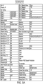
- a set up sheet 104 is configured with the die tooling, main extruder heat settings, and material recipe listed (see FIGURES 5A and 5B for a sample set up data sheet).
- This set up sheet 104 is used to prepare the manufacturing line, step 106.
- a microcontroller determines whether the line is set with the correct die assembly in step 108. If not, the set up sheet 104 is referenced in step 110 such that the correct die assembly is set. Once the correct die assembly is set in step 110 or confirmed in step 108, the microcontroller verifies whether the material recipe is correctly programmed in the line in step 112.
- step 114 the program recipe is referenced in step 114 from set up sheet 104.
- the microcontroller verifies whether the extruder heat setting are correct in step 116. If not, the heat settings of the extruder are referenced from set up sheet 104 and corrected in step 118.
- the manufacturing line begins to string up the foam bulb in step 120, and in step 122 the microcontroller instructs the foaming procedure to execute pursuant to the set up sheet 104. The microcontroller then runs the line for 5 minutes in step 124 to allow the pressure of the material to stabilize. A counter 126 confirms when the 5 minute stabilization period has run.
- step 128 the part is quality checked in step 128 via an optical inspection device, and if it does not pass the quality test, the speed of the extruders is manipulated in step 130 until the quality is acceptable. Once the quality is acceptable, the quality foam bulb is taken off the assembly line in step 132 (and reeled or cut to length and packaged).
- the line includes a material TPV/CFA, for example) mixing and drying vessel 200 which conveys the mixed/dried material to a material distribution vessel 202 that will distribute the materials to a main extruder 204 via a hopper 206.
- Polypropylene distribution vessel 208 is set up in parallel with vessel 202, and distributes the PP material to a first co-extruder 210.
- a slip material vessel 212 also is st up in parallel and distributes slip material to a second co-extruder 214.
- Main extruder 204, first extruder 210 and second co-extruder 214 are positioned to extrude the materials into a three piece extrusion profile die 300 that includes three material exits (one for the foamed PV material, one for the PP material, and one for the low friction slip material).
- the extruded weather-strip then enters a sizer plate 216 that is at the leading end of a cooling water tank 218 that is filled with 50 degree F water.
- a water chiller 220 maintains the water at the chilled temperature.
- the weather-strips As the weather-strips is pulled through the water tank 218 it then passes a blower 222 that blows off excess water, before passing through the puller/cutter 224 that pulls the weather-strip though the entire line and cuts it into desired lengths or the product passes through cutter device to be wound onto a reel by a winder 226.
- FIG. 7 shows a more detailed view of some of the equipment.
- Mixing and drying vessel 200 includes a TPE holding cell 228 and a PP holding cell 230.
- the TPE material is delivered to a weigh scale blender 232 where the CFA and TPV materials are mixed and then passed into a drier 234.
- FIG. 8 show more details of die 300 used to form the weather-strip.
- Die 300 comprises three plates: a back plate 302, a compression plate 304, and a front plate 306. Material enters back plate 302 from the extruders 204, 210, and 214 and exits die 300 through front plate 306.
- the back plate 302 includes the main extruder input 308 where the micro-cellular foam material is introduced into die 300.
- a co-extrusion input is provided for introduction of the PP material into die 300 (and a separate input can be provided for slip agent entrance).
- a splitter separates the main extruder materials into two sections - one for the bulb and one for the barbs.
- Back plate's back face matches the face of the extruder's adaptor die which is the first face of the profile die assembly that material is introduced.
- a mandrel 320 is inserted into compression plate supplies air into the die 300 which is critical in tolerancing and processing.
- the mandrel 320 extends about a half an inch from the front face of the die 300. This extra length aids in improving melt strength upon exiting the die prior to cooling in the water tank.
- the material After exiting compression plate 304, the material hits the front face of the front plate 306. Upon exiting the front face of the front plate the various separate channels derived from the two materials merging together connect as one in the final opening.
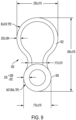
- a high pocket profile weather-strips 500 see FIG. 9 , having a bulbous portion 502 and a cylindrical/bulb shaped portion 504 of smaller diameter than the bulbous portion.
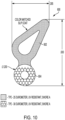
- a weather-strip 600 see FIG. 10 , having a tear drop shaped (triangularly slanted) upper bulb portion 602 of 25 durometer and a cylindrical lower portion 604 of 30 durometer, wherein the diameter of the lower portion is smaller in dimension that the length of the bulb portion.
- FIG. 10 see FIG.
- a weather seal 700 having the micro-cellular foam bulb 702, polypropylene spine 704 and micro-cellular foam barbs 706 just like with weather seal 10, but further including a pair of sealing flaps 708 of about the same dimensions as the barbs 706 that extend diagonally upward from the top of bulb 702. Sealing flaps 708 extend the sealing area when compressed against mating surface.
- multi-hollow bulb profiles such as those taught in the Applicant's prior pending U.S. application, published as US 2012/0260579 , and PCT Patent Application, No. US 2012/033773 ( PCT Publication No. 2012/142574 ), could be produced using the micro-cellular foam manufacturing process.
- the micro-cellular foam composition of the sealing members in the various weather-strips is an aspect that provides the stated utility and improvements over the art, and each can be manufactured on a line as described herein.
Landscapes
- Engineering & Computer Science (AREA)
- Mechanical Engineering (AREA)
- Civil Engineering (AREA)
- Structural Engineering (AREA)
- Physics & Mathematics (AREA)
- Thermal Sciences (AREA)
- Extrusion Moulding Of Plastics Or The Like (AREA)
- Molding Of Porous Articles (AREA)
- Sealing Material Composition (AREA)
- Gasket Seals (AREA)
Description
- The present disclosure is directed generally to weather seals used on windows and doors.
- Weather seals or weather-strips are commonly attached to the edges of doors and windows to decrease or prevent air from permeating between the interior and exterior of the door or window. Weather seals are also used to seal between the moving components of a window and door. Most typically weather seals are composed of thermoplastic elastomers or EPDM rubber, wrapped urethane foam or other flexible thermoset materials. These materials provide flexibility, resiliency, durability, and generally have low coefficients of friction and provide a consistent low closing force. Minimizing the loss of functional height of the weather seal over the life of the window or door is very important. Examples of weather seals are known e.g. from
DE 20 2004 003637 U1 andUS 2003/157316 A1 . - More advanced weather seals feature multiple bulbs and sealing flaps that extend the reach of a bulb seal. Some advanced or higher performance weatherseals have a solid foam center made from urethane foam or a TPE water blown foam. In some cases a hollow foam may be used to reduce closing forces. The materials and processing methods used to make foam filled seals are complex, expensive and require multiple steps. Urethane seals are not recyclable and utilize a two-part chemistry process that requires special handling methods. The two advanced weathers seals described above will use at least three different materials requiring three extruders and if they add a slip coating to reduce friction, a fourth extruder is required. This results in an expensive process that takes up a considerable amount of space. These processes also require highly skilled workers due to the complexity of the processes used.
- Accordingly, there is a need in the art for a more cost-effective solution that produces a resilient foamed bulb seal with insertion barbs that is recyclable and has a low closing force and a very low loss of functional height over time. This cost effective and environmental friendly solution would use two, or at most three conventional extruders in a single step process if a slip coating is required.
- The present invention is directed to a micro-cellular foam weather seal as defined in
claim 1 and to a method as defined inclaim 6 for manufacturing the seal. - According to an aspect is a weather seal for use on a weather permeable barrier separating the indoor from the outdoor, comprising: an elongated, compressible micro-cellular foam bulb adapted for connection to the barrier; and an elongated, compressible micro-cellular foam element extending along the length of the foam bulb, wherein the foam element is spaced from the barrier.
- According to an embodiment, the weather seal further comprises a silicone slip agent incorporated therein.
- The weather seal further comprises a polypropylene member attached to and extending the length of the foam bulb and to which the foam element is attached.
- According to an embodiment, the polypropylene member comprises an elongated spine having opposing surfaces and the foam element comprises at least one barb extending off of each surface of the spine.
- According to an embodiment, the weather seal further comprises a pair of sealing flaps that extend diagonally upward from the top of bulb, opposite the spine.
- According to an embodiment not covered by the invention, the foam bulb is of a first predetermined diameter and the foam element comprises a bulb-shape and is of a second diameter smaller than the first diameter.
- According to an embodiment not covered by the invention, the foam bulb is tear-drop shaped and or a predetermined length and the foam element is of a bulb-shape having a diameter that is smaller in dimension than the predetermined length.
- According to an embodiment, the bulb has hardness in the range of 10 to 75 durometer on a shore A scale and the foam element has a hardness in the range of 10 to 75 durometer on a shore A scale.
- According to an aspect is a method for manufacturing a micro-cellular foam weather seal for use on a weather permeable barrier separating the indoor from the outdoor and having an elongated, compressible micro-cellular foam bulb adapted for connection to the barrier and an elongated, compressible micro-cellular foam element extending along the length of the foam bulb, wherein the foam element is spaced from the barrier, wherein the weather seal further comprises a polypropylene member attached to and extending the length of the foam bulb and to which the foam element is attached, the method comprising the steps of: delivering the micro-cellular foam material from a storage cell to a weigh scale blender and then to a drier; delivering the micro-cellular foam material from the drier to a main extruder; delivering a polypropylene material from a storage cell to a first co-extruder; pulling the micro-cellular foam material and the polypropylene material from through the main extruder and first co-extruder, respectively, and into a die; forming the weather seal in the die; pulling the weather seal from the die and into a sizer plate; pulling the weather seal from the sizer plate into a cooling tank; blowing off excess water from the weather seal after it passes out of the cooling tank; and winding the weather seal on a reel.
- According to an embodiment, the method further comprises the step of providing a second co-extruder and delivering a slip agent material into the second co-extruder.
- According to an embodiment, the method further comprises the step of injecting the slip agent material from the second c-extruder into the die, whereby the slip agent material will coat the weather strip as it comes out of the die.
- According to an embodiment, the method further comprises the step of optically inspecting the weather strip as it comes out of the cooling tank.
- According to an embodiment, the method further comprises the step of maintaining the water in the cooling tank at a predetermined temperature.
- These and other aspects of the invention will be apparent from the embodiments described below.
- The present invention will be more fully understood and appreciated by reading the following Detailed Description in conjunction with the accompanying drawings, in which:
-
FIG. 1 is a perspective view of a weather seal, in accordance with an embodiment. -
FIG. 2 is a perspective view of a weather seal attached to a door, in accordance with an embodiment. -
FIG. 3 is a cross-sectional view of a weather seal taken along line 3-3 ofFIG. 1 , in accordance with an embodiment. -
FIG. 4 is a flow chart illustrating a manufacturing process, in accordance with an embodiment. -
FIGURES 5A and5B is an exemplar set up sheet split into two halves for purposes of convenience, in accordance with an embodiment. -
FIG. 6 is a box diagram illustrating a manufacturing line, in accordance with an embodiment. -
FIG. 7 is a detailed box diagram illustrating a manufacturing line, in accordance with an embodiment. -
FIG. 8 is a side elevation view of a die, in accordance with an embodiment. -
FIG. 9 is a cross-sectional view of a weather seal, in accordance with an embodiment that is not covered by the invention. -
FIG. 10 is a cross-sectional view of a weather seal, in accordance with an embodiment that is not covered by the invention. -
FIG. 11 is a cross-sectional view of a weather seal, in accordance with an embodiment. - The present disclosure describes a micro-cellular thermoplastic elastomer foam weather seal. The material used for the weather seal may be any of: TPE - Thermoplastic Elastomers, TPV- Thermoplastic Vulcanizates, or TPO- Thermo plastic Olefins.
- Referring to
FIG. 1 , in one embodiment, is a micro-cellularfoam weather seal 10, generally comprising an elongated, bulb-like body 12, and anelongated barb element 14 that extends along the length ofbody 12.Fin element 14 comprises a fin/spine 16 that has opposing, planar surfaces, and a series ofbarbs 18 that extend outwardly and at an angle towards thebody 12 from each planar surface of fin/spine 16.Barbs 18 are shorter in width than the height of fin/spine 16 and are positioned in parallel, laterally spaced relation to one another along the height of the fin/spine 16. -
Barbs 18 andbody 12 are composed of a thermoplastic elastomer with a chemical foaming agent (to produce a microcellular foam), while fin/spine 16 is composed of polypropylene. The thermoplastic elastomer has a Shore A hardness of 10 durometer to 75 durometer, and more preferably, 25 to 65 and the chemical foaming agent reduces the density by 10% - 40%.Body 12 has a preferable thickness of 0.020" to 0.200". - Because of the microcellular foam composition of
weather seal 10, it has the flexibility and resiliency to wrap around corners and maintain a pliable 90-degree angle, as shown inFIG. 2 . In addition, this pliability permits asingle weather strip 10 to be used on, for example, the bottom and side edges of a barrier between the indoors and outdoors, such as a door orwindow 20, as shown inFIG. 2 , thus eliminating seams between strips of weather seal as would be necessary but for the pliability provided byseal 10. - In addition to the advantages of enhanced pliability, the microcellular foam composition lowers the cost and reduces the weight of the seal. Furthermore, the microcellular foam lowers the closing forces needed to be exerted by the user, thereby reducing pressure on the door/window hardware (closing force is no more than 5 lbs. per foot in most common designs); this is particularly important for installations that are focused on compliance with the Americans with Disabilities Act. Also, the compression set resistance is approximately 10% or lower.
- The foaming agent used to form
seal 10 is also capable of receiving asilicone slip agent 22 that will reduce the coefficient of friction by at least 20%. This will further enhance the seal's advantages beyond its low closing force and light weight. Coloring agents could also be added for aesthetics. The desired lower coefficient of friction can be achieved by adding the slip agent into the polymer mix or it can be achieved by selectively coextruding a thin layer of the slip material on the surface of the weatherseal in the area that will be in contact with the mating surface - To manufacture
seal 10, a co-extrusion of two materials, both of which are foamed, is employed.Barbs 18 are foamed which simplifies the tooling design, resulting in two extruders being needed. An extended mandrel is used to improve the melt strength of the material as the foaming occurs when the material exits the die face and hits atmospheric pressure. The extended mandrel provides enhanced strength until the material gets closer to the water-cooling tank. - With reference to
FIG. 4 , a flow chart that illustrates the manufacturing process employed is provided. For purposes of manufacturing afoam bulb 100, wherein the part will be printed 102, a set upsheet 104 is configured with the die tooling, main extruder heat settings, and material recipe listed (seeFIGURES 5A and5B for a sample set up data sheet). This set upsheet 104 is used to prepare the manufacturing line,step 106. A microcontroller determines whether the line is set with the correct die assembly instep 108. If not, the set upsheet 104 is referenced instep 110 such that the correct die assembly is set. Once the correct die assembly is set instep 110 or confirmed instep 108, the microcontroller verifies whether the material recipe is correctly programmed in the line instep 112. If not, the program recipe is referenced instep 114 from set upsheet 104. Once the recipe is verified, the microcontroller verifies whether the extruder heat setting are correct instep 116. If not, the heat settings of the extruder are referenced from set upsheet 104 and corrected instep 118. Once verified, the manufacturing line begins to string up the foam bulb instep 120, and instep 122 the microcontroller instructs the foaming procedure to execute pursuant to the set upsheet 104. The microcontroller then runs the line for 5 minutes instep 124 to allow the pressure of the material to stabilize. Acounter 126 confirms when the 5 minute stabilization period has run. Once run and the manufacture of a foam bulb is executed the part is quality checked instep 128 via an optical inspection device, and if it does not pass the quality test, the speed of the extruders is manipulated instep 130 until the quality is acceptable. Once the quality is acceptable, the quality foam bulb is taken off the assembly line in step 132 (and reeled or cut to length and packaged). - With reference to
FIG. 6 , a block diagram of the manufacturing line is provided. The line includes a material TPV/CFA, for example) mixing and dryingvessel 200 which conveys the mixed/dried material to amaterial distribution vessel 202 that will distribute the materials to amain extruder 204 via ahopper 206.Polypropylene distribution vessel 208 is set up in parallel withvessel 202, and distributes the PP material to afirst co-extruder 210. Aslip material vessel 212 also is st up in parallel and distributes slip material to asecond co-extruder 214.Main extruder 204,first extruder 210 andsecond co-extruder 214 are positioned to extrude the materials into a three piece extrusion profile die 300 that includes three material exits (one for the foamed PV material, one for the PP material, and one for the low friction slip material). Once exiting thedie 300, the extruded weather-strip then enters asizer plate 216 that is at the leading end of a coolingwater tank 218 that is filled with 50 degree F water. Awater chiller 220 maintains the water at the chilled temperature. As the weather-strips is pulled through thewater tank 218 it then passes ablower 222 that blows off excess water, before passing through the puller/cutter 224 that pulls the weather-strip though the entire line and cuts it into desired lengths or the product passes through cutter device to be wound onto a reel by awinder 226. -
FIG. 7 shows a more detailed view of some of the equipment. Mixing and dryingvessel 200 includes aTPE holding cell 228 and aPP holding cell 230. The TPE material is delivered to aweigh scale blender 232 where the CFA and TPV materials are mixed and then passed into a drier 234. -
FIG. 8 show more details ofdie 300 used to form the weather-strip.Die 300 comprises three plates: aback plate 302, acompression plate 304, and afront plate 306. Material enters backplate 302 from theextruders front plate 306. Theback plate 302 includes the main extruder input 308 where the micro-cellular foam material is introduced intodie 300. A co-extrusion input is provided for introduction of the PP material into die 300 (and a separate input can be provided for slip agent entrance). A splitter separates the main extruder materials into two sections - one for the bulb and one for the barbs. Back plate's back face matches the face of the extruder's adaptor die which is the first face of the profile die assembly that material is introduced. - A mandrel 320 is inserted into compression plate supplies air into the
die 300 which is critical in tolerancing and processing. The mandrel 320 extends about a half an inch from the front face of thedie 300. This extra length aids in improving melt strength upon exiting the die prior to cooling in the water tank. - After exiting
compression plate 304, the material hits the front face of thefront plate 306. Upon exiting the front face of the front plate the various separate channels derived from the two materials merging together connect as one in the final opening. - In addition to a barbed weather-strip, the same manufacturing process can be employed with different dies to form different profile weather-strips that are also composed of the foam material. For example, a high pocket profile weather-
strips 500, seeFIG. 9 , having abulbous portion 502 and a cylindrical/bulb shapedportion 504 of smaller diameter than the bulbous portion. Or a weather-strip 600, seeFIG. 10 , having a tear drop shaped (triangularly slanted)upper bulb portion 602 of 25 durometer and a cylindricallower portion 604 of 30 durometer, wherein the diameter of the lower portion is smaller in dimension that the length of the bulb portion. As another option, seeFIG. 11 , aweather seal 700 having themicro-cellular foam bulb 702,polypropylene spine 704 andmicro-cellular foam barbs 706 just like withweather seal 10, but further including a pair of sealingflaps 708 of about the same dimensions as thebarbs 706 that extend diagonally upward from the top ofbulb 702. Sealing flaps 708 extend the sealing area when compressed against mating surface. In addition, multi-hollow bulb profiles, such as those taught in the Applicant's prior pending U.S. application, published asUS 2012/0260579 , andPCT Patent Application, No. US 2012/033773 (PCT Publication No. 2012/142574 ), could be produced using the micro-cellular foam manufacturing process. The micro-cellular foam composition of the sealing members in the various weather-strips is an aspect that provides the stated utility and improvements over the art, and each can be manufactured on a line as described herein.
Claims (10)
- A weather seal (10) for use on a weather permeable barrier (20) separating the indoor from the outdoor, comprising:a. an elongated, compressible micro-cellular foam bulb (12) adapted for connection to the barrier; andb. an elongated, compressible micro-cellular foam element (18) extending along the length of the foam bulb (12), wherein in use the foam element (18) is spaced from the barrier; characterized byc. a polypropylene member (16) attached to and extending the length of the foam bulb (12) and to which the foam element (18) is attached.
- The weather seal (10) according to claim 1, further comprising a silicone slip agent (22) incorporated therein.
- The weather seal (10) according to claim 1, wherein the polypropylene member comprises an elongated spine (704) attached to the bottom of bulb portion and having opposing surfaces and the foam element comprises at least one barb (706) extending off of each surface of the spine (704).
- The weather seal (10) according to claim 3, further comprising a pair of sealing flaps (708) that extend diagonally upward from the top of bulb, opposite the spine.
- The weather seal (10) according to claim 1, wherein the bulb has hardness in the range of 10 to 75 durometer on a shore A scale and the foam element has a hardness in the range of 10 to 75 durometer on a shore A scale.
- A method for manufacturing a micro-cellular foam weather seal (10) according to claim 1, the method comprising the steps of:a. delivering the micro-cellular foam material from a storage cell to a weigh scale blender and then to a drier;b. delivering the micro-cellular foam material from the drier to a main extruder;c. delivering a polypropylene material from a storage cell to a first co-extruder;d. pulling the micro-cellular foam material and the polypropylene material from through the main extruder and first co-extruder, respectively, and into a die;e. forming the weather seal in the die;f. pulling the weather seal from the die and into a sizer plate;g. pulling the weather seal from the sizer plate into a cooling tank;h. blowing off excess water from the weather seal after it passes out of the cooling tank; andi. winding the weather seal on a reel.
- The method according to claim 6, comprising the further step of providing a second co-extruder and delivering a slip agent material into the second co-extruder.
- The method according to claim 6, comprising the further step of injecting the slip agent material from the second c-extruder into the die, whereby the slip agent material will coat the weather strip as it comes out of the die.
- The method according to claim 6, comprising the further step of optically inspecting the weather strip as it comes out of the cooling tank (218).
- The method according to claim 6, comprising the further step of maintaining the water in the cooling tank at a predetermined temperature.
Applications Claiming Priority (2)
| Application Number | Priority Date | Filing Date | Title |
|---|---|---|---|
| US16/570,815 US20210079718A1 (en) | 2019-09-13 | 2019-09-13 | Micro-Cellular Foam Weather Seal |
| PCT/US2020/048111 WO2021050279A1 (en) | 2019-09-13 | 2020-08-27 | Micro-cellular foam weather seal |
Publications (3)
| Publication Number | Publication Date |
|---|---|
| EP3973133A1 EP3973133A1 (en) | 2022-03-30 |
| EP3973133C0 EP3973133C0 (en) | 2025-05-14 |
| EP3973133B1 true EP3973133B1 (en) | 2025-05-14 |
Family
ID=72422308
Family Applications (1)
| Application Number | Title | Priority Date | Filing Date |
|---|---|---|---|
| EP20768225.3A Active EP3973133B1 (en) | 2019-09-13 | 2020-08-27 | Micro-cellular foam weather seal |
Country Status (5)
| Country | Link |
|---|---|
| US (2) | US20210079718A1 (en) |
| EP (1) | EP3973133B1 (en) |
| JP (1) | JP7682858B2 (en) |
| AU (1) | AU2020347090A1 (en) |
| WO (1) | WO2021050279A1 (en) |
Family Cites Families (19)
| Publication number | Priority date | Publication date | Assignee | Title |
|---|---|---|---|---|
| DE2031721A1 (en) * | 1970-06-10 | 1972-01-20 | Egger, Georg Michael, Wabern (Schweiz) | Method and device for producing rubber profiles |
| US3903224A (en) * | 1972-11-03 | 1975-09-02 | Res Plastics Ind Inc | Automotive body panel molded from polycarbonate foam |
| JPS57162213A (en) * | 1981-03-30 | 1982-10-06 | Showa Electric Wire & Cable Co | Method of producing highly foamable cable |
| DE3511840A1 (en) * | 1985-03-30 | 1986-10-09 | Hahn Verfahrenstechnik GmbH, 6053 Obertshausen | Container balance |
| US5503788A (en) * | 1994-07-12 | 1996-04-02 | Lazareck; Jack | Automobile shredder residue-synthetic plastic material composite, and method for preparing the same |
| JPH09243333A (en) * | 1996-03-06 | 1997-09-19 | Kinugawa Rubber Ind Co Ltd | Device for inspecting extrusion |
| JPH10244578A (en) * | 1997-03-06 | 1998-09-14 | Kinugawa Rubber Ind Co Ltd | Apparatus for inspecting extruded molded product |
| JP2000102960A (en) * | 1998-09-29 | 2000-04-11 | Toyo Tire & Rubber Co Ltd | Thermoplastic composite extruded product and method for producing the same |
| CA2287114A1 (en) * | 1998-11-23 | 2000-05-23 | Kenneth W. Rood | Motor vehicle seal assembly and method of manufacture |
| JP2001121973A (en) * | 1999-10-28 | 2001-05-08 | Hiroshima Kasei Ltd | Weather strip and method of manufacturing the same |
| US20020128420A1 (en) * | 2000-12-27 | 2002-09-12 | Simpson Scott S. | Polyurethane elastomers and method of manufacture thereof |
| US20030157316A1 (en) * | 2002-02-15 | 2003-08-21 | Jyawook Sam M. | Thermoplastic vehicle weather stripping |
| KR100463863B1 (en) * | 2002-07-08 | 2004-12-30 | 주식회사 화승알앤에이 | Manufacturing method for weather strip of automobile and weather strip which is manufactured by that method |
| DE202004003637U1 (en) * | 2004-03-05 | 2004-08-26 | Blau, Dieter | Profile for sealing gaps between garage door elements comprises clamping lips on the foot section, bow-shaped head section wall, and groove(s) between foot section and main section |
| JP5271692B2 (en) * | 2008-11-28 | 2013-08-21 | トキワケミカル工業株式会社 | Extruded product with core material |
| JP5468970B2 (en) * | 2010-04-19 | 2014-04-09 | 鬼怒川ゴム工業株式会社 | Thermoplastic elastomer foam composition and weatherstrip |
| FR2960188B1 (en) * | 2010-05-20 | 2012-05-18 | Hutchinson | THERMOPLASTIC FRAME FOR MOTOR VEHICLE SEALING OR TRIM PROFILE, INCORPORATING PROFILE AND METHOD OF MAKING FRAME |
| CA2834597C (en) | 2011-04-15 | 2015-12-22 | Ultrafab, Inc. | Multiple hollow bulb seal |
| JP5923079B2 (en) * | 2013-10-30 | 2016-05-24 | 化成工業株式会社 | Weather strip for vehicle |
-
2019
- 2019-09-13 US US16/570,815 patent/US20210079718A1/en not_active Abandoned
-
2020
- 2020-08-27 JP JP2022514604A patent/JP7682858B2/en active Active
- 2020-08-27 EP EP20768225.3A patent/EP3973133B1/en active Active
- 2020-08-27 AU AU2020347090A patent/AU2020347090A1/en active Pending
- 2020-08-27 WO PCT/US2020/048111 patent/WO2021050279A1/en not_active Ceased
-
2022
- 2022-08-30 US US17/899,261 patent/US12188297B2/en active Active
Also Published As
| Publication number | Publication date |
|---|---|
| EP3973133C0 (en) | 2025-05-14 |
| US20230160254A1 (en) | 2023-05-25 |
| EP3973133A1 (en) | 2022-03-30 |
| JP2022547059A (en) | 2022-11-10 |
| US20210079718A1 (en) | 2021-03-18 |
| US12188297B2 (en) | 2025-01-07 |
| WO2021050279A1 (en) | 2021-03-18 |
| AU2020347090A1 (en) | 2022-01-20 |
| JP7682858B2 (en) | 2025-05-26 |
| CA3141045A1 (en) | 2021-03-18 |
Similar Documents
| Publication | Publication Date | Title |
|---|---|---|
| US4538380A (en) | Low friction weather seal | |
| US10676985B2 (en) | Low compression-force TPE weatherseals | |
| US20110016796A1 (en) | Intumescent Weatherseal | |
| WO2001070861A3 (en) | Polyolefin foam for sound and thermal insulation | |
| US9399887B2 (en) | Weatherstripping | |
| GB2036148A (en) | Door- or window casing and a process for its manufacture | |
| US8474189B1 (en) | Weather strip for use with frame structures having sharp corners | |
| CZ20033045A3 (en) | Fire-resistant window | |
| US20140265051A1 (en) | Method for making multiple durometer bulb seals | |
| EP1036686B1 (en) | Weather strip | |
| US20130220418A1 (en) | Sealing material for photovoltaic cell and photovoltaic cell assembly | |
| US12188297B2 (en) | Method for manufacturing a micro-cellular foam weather seal | |
| CA3141045C (en) | Micro-cellular foam weather seal | |
| GB2318379A (en) | Sealing or finishing strips | |
| US20180283089A1 (en) | Sealed weatherstrip corner pads | |
| CN110984817A (en) | Door | |
| US20110131887A1 (en) | Weatherseal Having Flexible Projection | |
| US7430835B1 (en) | Door and frame for air handling unit | |
| US8178014B2 (en) | Methods of forming an elongated ethylenic foam structure | |
| CA2656010C (en) | Weatherstrip adapted to be captured in t-slots | |
| WO2012067961A2 (en) | Butyl-free freezer panel joints | |
| EP2010805B1 (en) | Sealing system | |
| CZ2001593A3 (en) | Strand-like glazing packing | |
| EP1010852A1 (en) | Sealing gasket and method of making and inserting the same | |
| CA2882991C (en) | Weatherstripping |
Legal Events
| Date | Code | Title | Description |
|---|---|---|---|
| STAA | Information on the status of an ep patent application or granted ep patent |
Free format text: STATUS: UNKNOWN |
|
| STAA | Information on the status of an ep patent application or granted ep patent |
Free format text: STATUS: THE INTERNATIONAL PUBLICATION HAS BEEN MADE |
|
| PUAI | Public reference made under article 153(3) epc to a published international application that has entered the european phase |
Free format text: ORIGINAL CODE: 0009012 |
|
| STAA | Information on the status of an ep patent application or granted ep patent |
Free format text: STATUS: REQUEST FOR EXAMINATION WAS MADE |
|
| 17P | Request for examination filed |
Effective date: 20211220 |
|
| AK | Designated contracting states |
Kind code of ref document: A1 Designated state(s): AL AT BE BG CH CY CZ DE DK EE ES FI FR GB GR HR HU IE IS IT LI LT LU LV MC MK MT NL NO PL PT RO RS SE SI SK SM TR |
|
| DAV | Request for validation of the european patent (deleted) | ||
| DAX | Request for extension of the european patent (deleted) | ||
| P01 | Opt-out of the competence of the unified patent court (upc) registered |
Effective date: 20230526 |
|
| STAA | Information on the status of an ep patent application or granted ep patent |
Free format text: STATUS: EXAMINATION IS IN PROGRESS |
|
| 17Q | First examination report despatched |
Effective date: 20230911 |
|
| RIN1 | Information on inventor provided before grant (corrected) |
Inventor name: HAYWARD, KYLE Inventor name: BABIN, DANIEL Inventor name: DEMELLO, ALAN J. |
|
| REG | Reference to a national code |
Ref legal event code: R079 Ipc: E06B0007230000 Ref country code: DE Ref legal event code: R079 Ref document number: 602020051297 Country of ref document: DE Free format text: PREVIOUS MAIN CLASS: E06B0007000000 Ipc: E06B0007230000 |
|
| GRAP | Despatch of communication of intention to grant a patent |
Free format text: ORIGINAL CODE: EPIDOSNIGR1 |
|
| STAA | Information on the status of an ep patent application or granted ep patent |
Free format text: STATUS: GRANT OF PATENT IS INTENDED |
|
| RIC1 | Information provided on ipc code assigned before grant |
Ipc: B29C 48/49 20190101ALI20250212BHEP Ipc: B29C 48/12 20190101ALI20250212BHEP Ipc: B29C 48/00 20190101ALI20250212BHEP Ipc: B29C 44/50 20060101ALI20250212BHEP Ipc: B29C 44/22 20060101ALI20250212BHEP Ipc: E06B 7/23 20060101AFI20250212BHEP |
|
| INTG | Intention to grant announced |
Effective date: 20250221 |
|
| GRAS | Grant fee paid |
Free format text: ORIGINAL CODE: EPIDOSNIGR3 |
|
| GRAA | (expected) grant |
Free format text: ORIGINAL CODE: 0009210 |
|
| STAA | Information on the status of an ep patent application or granted ep patent |
Free format text: STATUS: THE PATENT HAS BEEN GRANTED |
|
| AK | Designated contracting states |
Kind code of ref document: B1 Designated state(s): AL AT BE BG CH CY CZ DE DK EE ES FI FR GB GR HR HU IE IS IT LI LT LU LV MC MK MT NL NO PL PT RO RS SE SI SK SM TR |
|
| REG | Reference to a national code |
Ref country code: GB Ref legal event code: FG4D |
|
| REG | Reference to a national code |
Ref country code: CH Ref legal event code: EP |
|
| REG | Reference to a national code |
Ref country code: IE Ref legal event code: FG4D |
|
| REG | Reference to a national code |
Ref country code: DE Ref legal event code: R096 Ref document number: 602020051297 Country of ref document: DE |
|
| U01 | Request for unitary effect filed |
Effective date: 20250616 |
|
| P04 | Withdrawal of opt-out of the competence of the unified patent court (upc) registered |
Free format text: CASE NUMBER: APP_29544/2025 Effective date: 20250621 |
|
| U07 | Unitary effect registered |
Designated state(s): AT BE BG DE DK EE FI FR IT LT LU LV MT NL PT RO SE SI Effective date: 20250625 |
|
| U20 | Renewal fee for the european patent with unitary effect paid |
Year of fee payment: 6 Effective date: 20250807 |
|
| PG25 | Lapsed in a contracting state [announced via postgrant information from national office to epo] |
Ref country code: ES Free format text: LAPSE BECAUSE OF FAILURE TO SUBMIT A TRANSLATION OF THE DESCRIPTION OR TO PAY THE FEE WITHIN THE PRESCRIBED TIME-LIMIT Effective date: 20250514 |
|
| PG25 | Lapsed in a contracting state [announced via postgrant information from national office to epo] |
Ref country code: NO Free format text: LAPSE BECAUSE OF FAILURE TO SUBMIT A TRANSLATION OF THE DESCRIPTION OR TO PAY THE FEE WITHIN THE PRESCRIBED TIME-LIMIT Effective date: 20250814 Ref country code: GR Free format text: LAPSE BECAUSE OF FAILURE TO SUBMIT A TRANSLATION OF THE DESCRIPTION OR TO PAY THE FEE WITHIN THE PRESCRIBED TIME-LIMIT Effective date: 20250815 |
|
| PG25 | Lapsed in a contracting state [announced via postgrant information from national office to epo] |
Ref country code: PL Free format text: LAPSE BECAUSE OF FAILURE TO SUBMIT A TRANSLATION OF THE DESCRIPTION OR TO PAY THE FEE WITHIN THE PRESCRIBED TIME-LIMIT Effective date: 20250514 |
|
| PG25 | Lapsed in a contracting state [announced via postgrant information from national office to epo] |
Ref country code: HR Free format text: LAPSE BECAUSE OF FAILURE TO SUBMIT A TRANSLATION OF THE DESCRIPTION OR TO PAY THE FEE WITHIN THE PRESCRIBED TIME-LIMIT Effective date: 20250514 |
|
| PG25 | Lapsed in a contracting state [announced via postgrant information from national office to epo] |
Ref country code: RS Free format text: LAPSE BECAUSE OF FAILURE TO SUBMIT A TRANSLATION OF THE DESCRIPTION OR TO PAY THE FEE WITHIN THE PRESCRIBED TIME-LIMIT Effective date: 20250814 |
|
| PG25 | Lapsed in a contracting state [announced via postgrant information from national office to epo] |
Ref country code: IS Free format text: LAPSE BECAUSE OF FAILURE TO SUBMIT A TRANSLATION OF THE DESCRIPTION OR TO PAY THE FEE WITHIN THE PRESCRIBED TIME-LIMIT Effective date: 20250914 |
|
| PG25 | Lapsed in a contracting state [announced via postgrant information from national office to epo] |
Ref country code: SM Free format text: LAPSE BECAUSE OF FAILURE TO SUBMIT A TRANSLATION OF THE DESCRIPTION OR TO PAY THE FEE WITHIN THE PRESCRIBED TIME-LIMIT Effective date: 20250514 |
|
| PG25 | Lapsed in a contracting state [announced via postgrant information from national office to epo] |
Ref country code: CZ Free format text: LAPSE BECAUSE OF FAILURE TO SUBMIT A TRANSLATION OF THE DESCRIPTION OR TO PAY THE FEE WITHIN THE PRESCRIBED TIME-LIMIT Effective date: 20250514 |
|
| PG25 | Lapsed in a contracting state [announced via postgrant information from national office to epo] |
Ref country code: SK Free format text: LAPSE BECAUSE OF FAILURE TO SUBMIT A TRANSLATION OF THE DESCRIPTION OR TO PAY THE FEE WITHIN THE PRESCRIBED TIME-LIMIT Effective date: 20250514 |
|
| PLBE | No opposition filed within time limit |
Free format text: ORIGINAL CODE: 0009261 |
|
| STAA | Information on the status of an ep patent application or granted ep patent |
Free format text: STATUS: NO OPPOSITION FILED WITHIN TIME LIMIT |
|
| REG | Reference to a national code |
Ref country code: CH Ref legal event code: H13 Free format text: ST27 STATUS EVENT CODE: U-0-0-H10-H13 (AS PROVIDED BY THE NATIONAL OFFICE) Effective date: 20260324 |
|
| REG | Reference to a national code |
Ref country code: CH Ref legal event code: L10 Free format text: ST27 STATUS EVENT CODE: U-0-0-L10-L00 (AS PROVIDED BY THE NATIONAL OFFICE) Effective date: 20260325 |
|
| PG25 | Lapsed in a contracting state [announced via postgrant information from national office to epo] |
Ref country code: MC Free format text: LAPSE BECAUSE OF FAILURE TO SUBMIT A TRANSLATION OF THE DESCRIPTION OR TO PAY THE FEE WITHIN THE PRESCRIBED TIME-LIMIT Effective date: 20250514 |
|
| 26N | No opposition filed |
Effective date: 20260217 |
|
| PG25 | Lapsed in a contracting state [announced via postgrant information from national office to epo] |
Ref country code: CH Free format text: LAPSE BECAUSE OF NON-PAYMENT OF DUE FEES Effective date: 20250831 |
|
| GBPC | Gb: european patent ceased through non-payment of renewal fee |
Effective date: 20250827 |