EP3973095B1 - Dreidimensionaler gewebeträger und verfahren zu seiner herstellung - Google Patents
Dreidimensionaler gewebeträger und verfahren zu seiner herstellung Download PDFInfo
- Publication number
- EP3973095B1 EP3973095B1 EP20731318.0A EP20731318A EP3973095B1 EP 3973095 B1 EP3973095 B1 EP 3973095B1 EP 20731318 A EP20731318 A EP 20731318A EP 3973095 B1 EP3973095 B1 EP 3973095B1
- Authority
- EP
- European Patent Office
- Prior art keywords
- fabric
- woven
- fabrics
- preform
- warp
- Prior art date
- Legal status (The legal status is an assumption and is not a legal conclusion. Google has not performed a legal analysis and makes no representation as to the accuracy of the status listed.)
- Active
Links
Images






Classifications
-
- D—TEXTILES; PAPER
- D03—WEAVING
- D03D—WOVEN FABRICS; METHODS OF WEAVING; LOOMS
- D03D25/00—Woven fabrics not otherwise provided for
- D03D25/005—Three-dimensional woven fabrics
-
- B—PERFORMING OPERATIONS; TRANSPORTING
- B29—WORKING OF PLASTICS; WORKING OF SUBSTANCES IN A PLASTIC STATE IN GENERAL
- B29B—PREPARATION OR PRETREATMENT OF THE MATERIAL TO BE SHAPED; MAKING GRANULES OR PREFORMS; RECOVERY OF PLASTICS OR OTHER CONSTITUENTS OF WASTE MATERIAL CONTAINING PLASTICS
- B29B11/00—Making preforms
- B29B11/14—Making preforms characterised by structure or composition
- B29B11/16—Making preforms characterised by structure or composition comprising fillers or reinforcement
-
- D—TEXTILES; PAPER
- D03—WEAVING
- D03D—WOVEN FABRICS; METHODS OF WEAVING; LOOMS
- D03D1/00—Woven fabrics designed to make specified articles
-
- D—TEXTILES; PAPER
- D03—WEAVING
- D03D—WOVEN FABRICS; METHODS OF WEAVING; LOOMS
- D03D3/00—Woven fabrics characterised by their shape
-
- D—TEXTILES; PAPER
- D10—INDEXING SCHEME ASSOCIATED WITH SUBLASSES OF SECTION D, RELATING TO TEXTILES
- D10B—INDEXING SCHEME ASSOCIATED WITH SUBLASSES OF SECTION D, RELATING TO TEXTILES
- D10B2505/00—Industrial
- D10B2505/02—Reinforcing materials; Prepregs
Definitions
- reinforced composite materials to produce structural components is now widespread, particularly in applications where their desirable characteristics are sought of being light in weight, strong, tough, thermally resistant, self-supporting, and adaptable to being formed and shaped.
- Such components are used, for example, in aeronautical, aerospace, satellite, recreational (as in racing boats and autos), and other applications.
- the structural components may be used in reinforcement components.
- the structural components can include reinforced composites having reinforcement preforms in the shape of I-Beams, H-Beams, or C-Beams, for example, made from reinforcement materials embedded in matrix materials.
- the support beam may be made from materials such as glass, carbon, ceramic, aramid, polyethylene, and/or other materials, which exhibit desired physical, thermal, chemical, and/or other properties, chief among which is great strength against stress failure.
- the constituent reinforcement preforms typically may be woven, knitted, nonwoven or otherwise oriented into desired configurations and shapes. Usually particular attention is paid to ensure the optimum utilization of the properties for which the constituent reinforcing materials have been selected.
- reinforcement preforms are combined with matrix material to form desired finished reinforcement structural components or to produce working stock for the ultimate production of finished reinforcement components.
- matrix material may be introduced to and into the preform, so that typically the reinforcement preform becomes encased in the matrix material and matrix material fills the interstitial areas between the constituent elements of the reinforcement preform.
- the matrix material may be any of a wide variety of materials, such as epoxy, polyester, vinyl-ester, ceramic, carbon and/or other materials, which also exhibit desired physical, thermal, chemical, and/or other properties.
- the materials chosen for use as the matrix may or may not be the same as that of the reinforcement preform and may or may not have comparable physical, chemical, thermal, or other properties.
- the reinforcement preform and the matrix material may then be cured and stabilized in the same operation by thermosetting or other known methods, and then subjected to other operations toward producing the desired component.
- the then solidified mass of the matrix material normally is very strongly adhered to the reinforcing material (e.g., the reinforcement preform).
- a typical combination of preform reinforcement support beams is made by the preforms at an angle (typically a right-angle) with respect to each other.
- Usual purposes for such angular arrangements of joined reinforcement preforms are to create a desired shape to form a reinforcement preform to strengthen the resulting composite structure that it produces against deflection or failure upon being exposed to exterior forces, such as pressure or tension.
- a related consideration is to make each juncture between the reinforcement support beams as strong as possible. Given the often desired very high strength of the reinforcement preform constituents, weakness of the juncture becomes, effectively, a "weak link" in a structural "chain".
- the support beams are attached at the juncture where they intersect.
- Most attachment schemes center on those acceptable for metals, e.g., using fasteners such as rivets, bolts, clips and the like.
- support beams in the shape of C-Beams intersecting one another have little area for attachment where they intersect.
- the standard construction method for beams in general includes one continuous primary beam to which the ends of secondary beams are attached.
- An improvement on this design incorporates continuous fiber across the intersection in the web of both the primary and secondary beams.
- the cut flanges could form a small lap shear joint with the continuous flange (See Figure 1 ), but there is a limited overlapping area available in the intersecting portion requiring reinforcement with brackets, fasteners, and/or an additional separate piece that acts as a sill across the joint.
- twists and “fibers”, “tows”, and “yarns” are used interchangeably in the following description.
- “Threads”, “fibers”, “tows”, and “yarns” as used herein includes monofilaments, multifilament yarns, twisted yarns, multifilament tows, textured yarns, braided tows, coated yarns, bicomponent yarns, as well as yarns made from stretch broken fibers of any materials known to those ordinarily skilled in the art.
- Yarns can be made of carbon, nylon, rayon, fiberglass, cotton, ceramic, aramid, polyester, metal, polyethylene glass, and/or other materials that exhibit desired physical, thermal, chemical, or other properties.
- fabric means warp fibers interwoven with weft fibers and a fabric can be either a single layer fabric or a multilayer fabric.
- multilayer fabric is used herein for convenience and includes single layer fabrics as well.
- folded is broadly used herein to mean “forming”, which includes unfolding, bending, and other such terms for manipulating the shape of a woven fabric.
- C-flange and “C-Beam” are used interchangeably to refer to a structure having a C-shaped cross-section.
- H-Beam and “I-Beam” are used to refer to structures having an H-, I-, T-, L-, or ⁇ -shaped (Pi-shaped) cross-section, respectively.
- support beam is used to include a beam having any cross-sectional shape.
- the disclosure is directed to structural components with reinforcing preforms in the shape of a support beam.
- a three-dimensional (3D) woven cruciform preform having arms with a C-shaped cross-section (C-Beams) and fiber continuity across the length of the arms or fiber continuity over at least the crossover portion where the C-Beam arms of the cruciform intersect.
- C-Beams C-shaped cross-section
- the disclosure provides for a woven C-Beam support preform that avoids the need to cut the fibers in the C-beam arms or to use fasteners in order to attach the arms where they intersect.
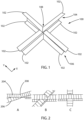
- FIG. 1 illustrates a model of a desired final shape of a 3D preform cruciform 100 having C-Beams 104,106.
- the C-Beams are woven to have continuous warps along the intersecting flanges 102 of the C-Beams.
- This arrangement provides a cruciform with C-Beams or arms having continuous fiber in both directions X, Y of the cruciform. Where the X-direction is the direction of the warp fibers in a first arm and the Y-direction is the direction of the warp fibers in a second arm. That is, the flanges 102 of the C-beams have continuous warp tows across the length of the cruciform and, in particular, across crossover portion 108, which is the location where the C-Beams of the cruciform intersect.
- the flanges of the C-Beam can provide an increase to the bending stiffness of the resultant cruciform reinforcing preform over C-Beam cruciform without fiber continuity across the crossover portion.
- the present disclosure provides for simultaneously achieving fabric continuity of fibers in both the X and Y direction of the cruciform.
- the simultaneous continuity is prevented in prior-art C-Beam cruciforms because the desired as-formed crossover location is different than the as-woven crossover location. That is, the weft fibers of the flanges prohibit the necessary sliding of the warp fibers in the crossover location to enable forming of the C-Beam flanges.
- FIG. 2C illustrates the change in position of this crossover location.
- FIG. 2 illustrates forming a C-Beam cruciform structure (from a top view) by rotating the arms (not visible) using a paper model for illustration.
- the added flanges (204, 206, and as in Figure 2 ) that form a C-Beam cruciform structure increases the stiffness over an un-flanged cruciform (that is, without flanges 102) when a force or load is applied along the line formed by the intersecting arms 204, 206.
- cutting the warp fibers in the flanges to facilitate intersection of the cruciform arms results in a discontinuity of fibers in one of the flange directions.
- the discontinuity of the warp fibers creates a weak spot that can degrade the performance of a structure to the limit of what a subsequently applied resin bond can transfer across the crossover portion.
- Maintaining continuous fiber throughout the flanges in both directions of a C-Beam cruciform can increase the tensile and compressive stiffness along the length of each arm of the resultant preform.
- the present invention enables warp fiber continuity simultaneously along each of the flanges of the arms of a C-Beam cruciform.
- the warp fibers float - that is, are not interwoven with weft fibers - in the crossover portion of the flanges throughout the range of motion of the arms. That is, the warp fibers in a flange of a first arm of the cruciform are free to slide against the warp fibers of a second arm of the cruciform in the crossover portion.
- This feature can enable the flat woven arms of a C-Beam to be rotated about the crossover portion into the as-formed geometry of the arms.
- Figure 3 illustrates one arm 300 of a C-Beam as woven.
- the C-Beam is flat woven.
- Edges 302, 304 of the flat-woven C-Beam will later be formed into flanges of the C-Beam.
- Warp fibers in edge portions 306, 308 of edges 302, 304 are not interwoven with weft fibers. As such, warp fibers in portions 306, 308 float.
- the floating of the warp fibers in edges 306, 308 can enable the warp fibers in the arm 300 to slide over warp fibers in another intersecting arm to fold the edges of the arm into the C-Beam cross-sectional shape.
- edge portions 302, 304 in which the warp fibers are floating across the width of the arm 300 can determine the length of the C-Beam flange when folded, which is typically in the range of 2,54 mm to 50,8 mm (0.1 inch to 2 inches), but greater and lesser lengths of flanges are contemplated.
- the dimension of edge portions 306, 308 along the length of arm 300 may be any width and length, but typically the width will match the width of edge portions 302, 304 and the length will accommodate the width of a crossing arm (not illustrated in FIG. 3 )..
- the dimensional ranges of edge portions 306, 308 range is not a limiting factor in the disclosed structure.
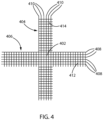
- Figure 4 illustrates a top view of the intersection of flanges after a flanged C-Beam cruciform has been formed.
- the cross hatching on the horizontal arm represents a flange of a first arm 406 of the C-Beam cruciform that is visible from the top and the cross hatching on the vertical arm represents a flange of a second arm 404 of the C-Beam cruciform.
- Flanges 404, 406 may be formed perpendicular to one another or at any desired angle for the final cruciform structure.
- first arm 406 The horizontal lines along the length of first arm 406 represent warp tows 408 of first arm 406.
- the lines perpendicular to the warp tows 408 represent the weft tows 412 of first arm 406.
- the vertical lines 410 along the length of the second arm 404 represent warp tows 410 of second arm 404.
- the lines perpendicular to the warp tows 410 represent the weft tows 414 of second arm 404.
- first arm 406 and second arm 404 cross The location where the first arm 406 and second arm 404 cross is the intersection - crossover portion 402 - of the cruciform.
- weft tows 412, 414 are not present in the flanges of the first and second arms in crossover portion 402 of the formed preform.
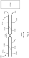
- Figure 5 illustrates a cross-sectional view in the warp direction of as-woven fabric preform 500 as the fabric comes off a loom.
- the preform illustrated includes two multilayer fabrics 502, 504 that will form a cruciform structure having one crossover portion 518.
- Multilayer fabric 502 is woven under multilayer fabric 504 before the crossover portion.
- Multilayer fabric 502 is woven over multilayer fabric 504 after the crossover portion.
- multilayer fabric 502 has surface 514A on one side of the fabric and 514B on the opposite side of the fabric before the crossover portion.
- Multilayer fabric 502 has surface 512A on one side of the fabric and 512B on the opposite side of the fabric after the crossover portion.
- multilayer fabric 504 has surface 510A on one side of the fabric and 510B on the opposite side of the fabric before the crossover portion.
- Multilayer fabric 504 has surface 516A on one side of the fabric and 516B on the opposite side of the fabric after the crossover portion.
- the warp fibers of the first and second multilayer fabrics float in the crossover portion where they will be folded into flanges and the warp fibers in the first and second multilayer fabrics are continuous across the crossover portion.
- the first multilayer fabric can later be used to form a first arm of the C-Beam cruciform.
- the second multilayer fabric can later be used to form a second arm of a C-Beam cruciform.
- the first and second multilayer fabrics are rotated about the crossover portion so that the fabrics are at a desired angle to one another. In a particular embodiment, the angle between the first and second multilayer fabrics is 90 degrees. However, other angles such as 45 degrees, etc. are contemplated.
- first multilayer fabric The edges of the first multilayer fabric are folded to form flanges so the first multilayer fabric has a C-shaped cross-section.
- edges of the second multilayer fabric are folded to form flanges so the second multilayer fabric has a C-shaped cross-section.
- the preform is a two-dimensional (flat-woven) structure having a first multilayer fabric woven over a second multilayer fabric for a desired length of the preform.
- the first multilayer fabric intersects with the second multilayer fabric at a crossover portion of the preform so that after the crossover portion the first multilayer fabric is woven underneath the second multilayer fabric. That is, the first and second multilayer fabrics are interwoven with one another at the crossover portion and are elsewhere not interwoven with one another in the preform in a cruciform structure having one crossover portion according to the present disclosure.
- Figures 6 through 11 show views in the forming of woven preform 500 having one crossover portion using the identification of surfaces in Figure 5 .
- Figure 6 is a top view of the flat-woven fabric preform prior to forming into a C-Beam structure with one crossover portion 518. Warp fibers in portions 506, 508 on edges 620, 622 of the fabric are not interwoven with weft fibers. As such, warp fibers in portions 506, 508 float.
- Surfaces 510A, 512A identified in Figure 5 are seen in the top view of the woven fabric preform on respective sides of a midpoint 614.
- Figure 7 is a bottom view of the fabric preform 500 of Figure 6 where areas 506, 508 interwoven in the top view are not interwoven in the bottom view.
- Surfaces 514A, 516A identified in Figure 5 are seen in the bottom view of the woven fabric preform on respective sides of midpoint 614.
- Figure 8 shows forming the flat-woven fabric illustrated in Figure 5 into a C-Beam cruciform by rotating fabrics 502, 504 with respect to one another.
- fabric surfaces 512A, 512B and 514A, 514B of multilayer fabric 502 are rotated in the direction of the arrows J and K shown in Figure 5 .
- Figure 9 is a top view showing the forming of the C-Beam cruciform of Figure 8 into a C-Beam cruciform. Edges 620, 622 are folded to form flanges 902, 904, respectively, resulting in the C-Beam cross-sectional shape. Warp fibers in crossover portion 518 are floating, which enables edges 620, 622 to be folded. The warp fibers in portion 506, for example, in the crossover portion 518 are not interwoven with weft fibers. As such, the warp fibers in multilayer fabric 502 in the crossover portion can slide over the floating warp fibers of multilayer fabric 504 in the crossover portion without being obstructed by weft fibers. Remaining edges are similarly folded to form C-Beam cross-sectional shapes on the other arms of the cruciform structure.
- Figure 10 shows a bottom view of the C-Beam cruciform formed in Figure 9 .
- warp fibers in crossover portion 518 are floating, which enables edges 620, 622 to be folded.
- the warp fibers in portion 508, for example, in the crossover portion 518 are not interwoven with weft fibers. As such, the warp fibers in multilayer fabric 502 in the crossover portion can slide over the floating warp fibers of multilayer fabric 504 in the crossover portion without being obstructed by weft fibers.
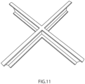
- the preform After forming the C-Beam cruciform structure, the preform can be impregnated with a matrix material to form a composite.
- a matrix material An example of the composite C-Beam cruciform is shown in Figure 11 .
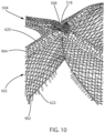
- Figure 12 illustrates three warp columns A, B, and C in the flange crossover portion of a C-Beam cruciform (after forming).
- Warp tows 1804 of the flange of the first arm and warp tows 1806 of the flange of the second arm are not interwoven with weft fibers.
- warp tows of the first arm 1804 are interwoven with warp tows 1806 of the second arm across the crossover portion 1802. This feature enables the arms of the C-Beams to rotate about the crossover portion when being formed from the as-woven preform into the desired cruciform shape.
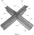
- the subject invention can also be applied to make an I-Beam cruciform preform 1300, shown in Figure 13 .
- the preform comprises a first arm 1306 and a second arm 1304.
- Each of first arm 1306 and second arm 1304 has two opposing flanges 1302.
- the first and second arms intersect at crossover portion 1308.
- the present invention is not limited to woven preforms having only one crossover portion that may be formed into C-Beam cruciform structures.
- Cruciform structures having C-Beam cross-sectional forms that are flat-woven with multiple crossover portions may be formed.
- Figures 14 to 16 illustrate cross-sectional views of multilayer fabrics that may be used to form cruciform structures. Preforms with other cross-sectional forms including, but not limited to, "H-Beam”, “I-Beam”, “T-Beam”, “L-Beam”, and " ⁇ -Beam” are contemplated as well.
- Figure 14 illustrates a cross-sectional view of a flat-woven preform having two multilayer fabrics 1402, 1404 and a single crossover portion 1400 1 .
- Multilayer fabric 1402 is woven over multilayer fabric 1404 on one side of crossover portion 1400 1 and under multilayer fabric 1404 on another side of the crossover portion.
- the preform can be formed in a C-Beam structure having a "cross” or "X-shape".
- Figure 15 illustrates a cross-sectional view of a flat-woven preform having four multilayer fabrics 1502, 1504, 1506, 1508 and four crossover portions 1500 1 , 1500 2 , 1500 3 , 1500 4 .
- Each multilayer fabric includes two crossover portions with each of two other multilayer fabrics.
- a first multilayer fabric is woven over a second multilayer woven fabric on one side of the crossover portion and under the second fabric on the other side of the crossover portion.
- multilayer fabric 1502 includes two crossover portions 1500 1 , 1500 4 with multilayer fabrics 1506 and 1508, respectively.
- Fabric 1502 is woven over fabric 1506 on one side of crossover portion 1500 1 and under fabric 1506 on the other side of crossover portion 1500 1 .
- Fabric 1502 is woven over fabric 1508 on one side of crossover portion 1500 4 and under fabric 1508 on the other side of crossover portion 1500 4 . A similar weaving may be accomplished for each of remaining fabrics 1504, 1506, 1508. In this embodiment, the result is a cruciform structure having the form of a "hash” or "number” symbol shape that bounds an open area 1518.
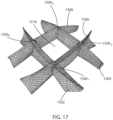
- Figure 17 is an illustration of the cruciform structure formed from the fabric illustrated in Figure 15 .
- the cruciform structure shown in Figure 17 includes four arms 1502, 1504, 1506, 1508. Each arm intersects with two other arms at crossover portions. As such, each arm has two crossover portions.
- Arm 1502 includes crossover portions 1500 1 , 1500 4 with multilayer fabrics 1506 and 1508, respectively;
- arm 1504 includes crossover portions 1500 2 , 1500 3 with multilayer fabrics 1506 and 1508, respectively;
- arm 1506 includes crossover portions 1500 1 , 1500 2 with multilayer fabrics 1502 and 1504, respectively;
- arm 1508 includes crossover portions 1500 3 , 1500 4 with multilayer fabrics 1504 and 1502, respectively.
- the result is a structure having the form of a "hash" or "number” symbol that bounds an open area 1518.
- Figure 16 illustrates a cross-sectional view of a flat-woven preform having six multilayer fabrics 1602, 1604, 1606, 1608, 1610, 1612 with nine crossover portions 1600 1 , 1600 2 , 1600 3 , 1600 4 , 1600 5 , 1600 6 , 1600 7 , 1600 8 , 1600 9 .
- Each of the fabrics includes three crossover portions with three other fabrics.
- fabric 1602 includes crossover portions 1600 1 , 1600 2 , 1600 3 with fabrics 1608, 1610, 1612, respectively.
- the preform woven in this manner results in the complex cruciform pattern illustrated.
- the woven preform can be impregnated with a matrix material.
- the matrix material includes epoxy, bismaleimide, polyester, vinyl-ester, ceramic, carbon, and other such materials.
Landscapes
- Engineering & Computer Science (AREA)
- Textile Engineering (AREA)
- Mechanical Engineering (AREA)
- Woven Fabrics (AREA)
- Moulding By Coating Moulds (AREA)
- Reinforced Plastic Materials (AREA)
- Looms (AREA)
Claims (28)
- Verfahren zum Herstellen einer gewebten Vorform, umfassend:Weben eines ersten Gewebes (502, 504, 1402, 1404) über ein zweites Gewebe (502, 504, 1402, 1404) in einem ersten Abschnitt der gewebten Vorform, wobei das erste und das zweite Gewebe (502, 504, 1402, 1404) jeweils Kettfasern enthalten, die mit Schussfasern miteinander verwoben sind;Verweben Kettfasern des ersten Gewebes (502, 504, 1402, 1404) mit Kettfasern des zweiten Gewebes (502, 504, 1402, 1404) an einem Kreuzungsabschnitt (518, 14001) der gewebten Vorform, so dass nach dem Kreuzungsabschnitt (518, 14001) das erste Gewebe (502, 504, 1402, 1404) unter dem zweiten Gewebe (502, 504, 1402, 1404) in einem zweiten Abschnitt der gewebten Vorform gewebt wird;wobei die Kettfasern in dem ersten und dem zweiten Gewebe (502, 504, 1402, 1404) über den Kreuzungsabschnitt (518, 14001) durchgehend sind, dadurch gekennzeichnet, dassdie Kettfasern an den Rändern des ersten Gewebes (502, 504, 1402, 1404) und die Kettfasern an den Rändern des zweiten Gewebes (502, 504, 1402, 1404) in dem Kreuzungsabschnitt (518, 14001) beweglich sind.
- Verfahren zum Herstellen einer gewebten Vorform nach Anspruch 1, wobei das erste Gewebe (502, 504, 1402, 1404) ein einlagiges Gewebe oder ein mehrlagiges Gewebe ist; und
wobei das zweite Gewebe (502, 504, 1402, 1404) ein einlagiges Gewebe oder ein mehrlagiges Gewebe ist. - Verfahren zum Herstellen einer gewebten Vorform nach einem der Ansprüche 1 bis 2, umfassend:
Drehen des ersten Gewebes (502, 504, 1402, 1404) um den Kreuzungsabschnitt (518, 14001), um einen Winkel in Bezug auf das zweite Gewebe (502, 504, 1402, 1404) zu bilden. - Verfahren zum Herstellen einer gewebten Vorform nach Anspruch 3, wobei der Winkel 90 Grad beträgt.
- Verfahren zum Herstellen einer gewebten Vorform nach einem der Ansprüche 3 oder 4, umfassend:
Falten der Ränder des ersten und des zweiten Gewebes (502, 504, 1402, 1404) um eine Achse, die sich parallel zur Kettrichtung erstreckt, sodass die Vorform eine Querschnittsform aufweist, die aus der Gruppe bestehend aus H-Webebreite, I-Webebreite, T-Webebreite, L-Webebreite und Pi-Webebreite ausgewählt wird. - Verfahren zum Herstellen einer gewebten Vorform nach einem der Ansprüche 3 oder 4, umfassend:Falten der Ränder des ersten Gewebes (502, 504, 1402, 1404) um eine Achse, die sich parallel zur Kettrichtung erstreckt, zu einem C-Webebreite; undFalten der Ränder des zweiten Gewebes (502, 504, 1402, 1404) um eine Achse, die sich parallel zur Kettrichtung erstreckt, zu einem C-Webebreite.
- Verfahren zum Herstellen einer VerbundTrägerstruktur, umfassend:Herstellen der gewebten Vorform nach Anspruch 6; undImprägnieren der gewebten Vorform mit einem Matrixmaterial.
- Gewebte Vorform, umfassend:ein erstes Gewebe (502, 504, 1402, 1404) aus Kettfasern, die mit Schussfasern miteinander verwoben sind;ein zweites Gewebe (502, 504, 1402, 1404) aus Kettfasern, die mit Schussfasern miteinander verwoben sind,wobei die Kettfasern des ersten Gewebes (502, 504, 1402, 1404) mit den Kettfasern des zweiten Gewebes (502, 504, 1402, 1404) an einem Kreuzungsabschnitt (518, 14001) miteinander verwoben werden, so dass die Kettfasern in dem ersten Gewebe (502, 504, 1402, 1404) und die Kettfasern in dem zweiten Gewebe (502, 504, 1402, 1404) über den Kreuzungsabschnitt (518, 14001) durchgehend sind,wobei das erste Gewebe und das zweite Gewebe (502, 504, 1402, 1404) anderswo als dem Kreuzungsabschnitt (518, 14001) nicht miteinander verwoben sind, dadurch gekennzeichnet, dassdie Kettfasern an den Rändern des ersten Gewebes (502, 504, 1402, 1404) und die Kettfasern an den Rändern des zweiten Gewebes (502, 504, 1402, 1404) in dem Kreuzungsabschnitt (518, 14001) beweglich sind.
- Gewebte Vorform nach Anspruch 8, wobei das erste Gewebe (502, 504, 1402, 1404) ein einlagiges Gewebe oder ein mehrlagiges Gewebe ist; und
wobei das zweite Gewebe (502, 504, 1402, 1404) ein einlagiges Gewebe oder ein mehrlagiges Gewebe ist. - Gewebte Vorform nach einem der Ansprüche 8 und 9, umfassend:ein drittes Gewebe aus Kettfasern, die mit Schussfasern miteinander verwoben sind, wobei das dritte Gewebe ein einlagige- oder ein mehrlagiges Gewebe ist,wobei die Kettfasern des dritten Gewebes mit den Kettfasern des zweiten Gewebes (502, 504, 1402, 1404) an einem Überkreuzungsabschnitt miteinander verwoben sind, so dass die Kettfasern in dem dritten Gewebe und die Kettfasern in dem zweiten Gewebe (502, 504, 1402, 1404) über den Überkreuzungsabschnitt durchgehend sind,wobei das dritte Gewebe und das zweite Gewebe (502, 504, 1402, 1404) anderswo als dem Kreuzungsabschnitt nicht miteinander verwoben sind,wobei das erste, das zweite und das dritte Gewebe einen Winkel mit mindestens einem anderen der übrigen Gewebe bilden.
- Gewebte Vorform nach einem der Ansprüche 8 und 9, wobei das erste und das zweite Gewebe (502, 504, 1402, 1404) um eine Achse gefaltet sind, die sich parallel zur Kettrichtung erstreckt, um eine Querschnittsform zu erhalten, die aus der Gruppe bestehend aus H-Webebreite, I-Webebreite, T-Webebreite, L-Webebreite und Pi-Webebreite ausgewählt wird.
- Gewebte Vorform nach einem der Ansprüche 8 bis 10, wobei das erste und das zweite Gewebe (502, 504, 1402, 1404) jeweils um eine Achse, die sich parallel zur Kettrichtung erstreckt, zu einem C-Webebreite gefaltet sind.
- Verbundträgerstruktur, umfassend:die gewebte Vorform nach einem der Ansprüche 8 bis 10; undein Matrixmaterial.
- Verfahren zum Herstellen einer gewebten Vorform, umfassend:Weben mindestens drei Geweben (1502, 1504, 1506, 1508, 1602, 1604, 1606, 1608, 1610, 1612) enthaltend Kettfasern, die mit Schussfasern miteinander verwoben sind, wobei jedes Gewebe ein erstes Gewebe (1502, 1504, 1506, 1508, 1602, 1604, 1606, 1608, 1610, 1612) aufweist, das über ein zweites Gewebe (1502, 1504, 1506, 1508, 1602, 1604, 1606, 1608, 1610, 1612) in einem ersten Abschnitt der gewebten Vorform gewebt wird;Verweben jedes der mindestens drei Gewebe (1502, 1504, 1506, 1508, 1602, 1604, 1606, 1608, 1610, 1612) mit mindestens einem verbleibenden gewebten Gewebe an einem jeweiligen Kreuzungsabschnitt (15001, 15004, 16001, 16002, 16003, 16004, 16005, 16006, 16007, 16008, 16009), so dass mindestens zwei Kreuzungsabschnitte (15001, 15004, 16001, 16002, 16003, 16004, 16005, 16006, 16007, 16008, 16009) in jedem Gewebe (1502, 1504, 1506, 1508, 1602, 1604, 1606, 1608, 1610, 1612) vorhanden sind;wobei nach jedem Kreuzungsabschnitt (15001, 15004, 16001, 16002, 16003, 16004, 16005, 16006, 16007, 16008, 16009) der mindestens drei gewebten Geweben (1502, 1504, 1506, 1508, 1602, 1604, 1606, 1608, 1610, 1612) ein kreuzendes Gewebe(1502, 1504, 1506, 1508, 1602, 1604, 1606, 1608, 1610, 1612), das über einem anderen Gewebe (1502, 1504, 1506, 1508, 1602, 1604, 1606, 1608, 1610, 1612) gewebt wird, unter dem anderen Gewebe (1502, 1504, 1506, 1508, 1602, 1604, 1606, 1608, 1610, 1612) gewebt wird,wobei die Kettfasern in den kreuzenden Geweben (1502, 1504, 1506, 1508, 1602, 1604, 1606, 1608, 1610, 1612) über jeden Kreuzungsabschnitt (15001, 15004, 16001, 16002, 16003, 16004, 16005, 16006, 16007, 16008, 16009) durchgehend sind, dadurch gekennzeichnet, dassdie Kettfasern an den Ränder der mindestens drei Gewebe (1502, 1504, 1506, 1508, 1602, 1604, 1606, 1608, 1610, 1612) in jedem Kreuzungsabschnitt (15001, 15004, 16001, 16002, 16003, 16004, 16005, 16006, 16007, 16008, 16009) beweglich sind.
- Verfahren zum Herstellen einer gewebten Vorform nach Anspruch 14, wobei jedes der mindestens drei Gewebe (1502, 1504, 1506, 1508, 1602, 1604, 1606, 1608, 1610, 1612) ein einlagiges Gewebe oder ein mehrlagiges Gewebe ist.
- Verfahren zum Herstellen einer gewebten Vorform nach einem der Ansprüche 14 oder 15, umfassend:Drehen der mindestens drei Gewebe (1502, 1504, 1506, 1508, 1602, 1604, 1606, 1608, 1610, 1612) um die Kreuzungsabschnitte (15001, 15004, 16001, 16002, 16003, 16004, 16005, 16006, 16007, 16008, 16009), so dass die mindestens drei Gewebe (1502, 1504, 1506, 1508, 1602, 1604, 1606, 1608, 1610, 1612) einen Winkel mit mindestens einem anderen der mindestens drei Gewebe (1502, 1504, 1506, 1508, 1602, 1604, 1606, 1608, 1610, 1612) bilden,und optional Falten der Ränder jedes der mindestens drei Gewebe (1502, 1504, 1506, 1508, 1602, 1604, 1606, 1608, 1610, 1612) um eine Achse, die sich parallel zur Kettrichtung erstreckt, zu einem C-Webebreite.
- Verfahren zum Herstellen einer gewebten Vorform nach einem der Ansprüche 14 oder 15 und 16, wobei vier Gewebe (1502, 1504, 1506, 1508) vorhanden sind, wobei sich jedes Gewebe (1502, 1504, 1506, 1508) mit genau zwei anderen Geweben (1502, 1504, 1506, 1508) kreuzt.
- Verfahren zum Herstellen einer gewebten Vorform nach Anspruch 17, umfassend:
Falten der Ränder jedes der vier Gewebe (1502, 1504, 1506, 1508) um eine Achse, die sich parallel zur Kettrichtung erstreckt, zu einem C-Webebreite. - Verfahren zum Herstellen einer gewebten Vorform nach einem der Ansprüche 14 oder 15 und 16, umfassend:
Falten der Ränder jedes der mindestens drei Gewebe (1502, 1504, 1506, 1508, 1602, 1604, 1606, 1608, 1610, 1612) um eine Achse, die sich parallel zur Kettrichtung erstreckt, um eine Querschnittsform zu erhalten, die aus der Gruppe bestehend aus H-Webebreite, I-Webebreite, T-Webebreite, L-Webebreite und Pi-Webebreite ausgewählt wird. - Verfahren zum Herstellen einer VerbundTrägerstruktur, umfassend:Herstellen der gewebten Vorform nach Anspruch 18; undImprägnieren der gewebten Vorform mit einem Matrixmaterial.
- Verfahren zum Herstellen einer VerbundTrägerstruktur, umfassend:Herstellen der gewebten Vorform nach Anspruch 16; undImprägnieren der gewebten Vorform mit einem Matrixmaterial.
- Gewebte Vorform, umfassend:mindestens drei Gewebe (1502, 1504, 1506, 1508, 1602, 1604, 1606, 1608, 1610, 1612) aufweisend Kettfasern, die mit Schussfasern miteinander verwoben sind, wobei jedes gewebte Gewebe ein erstes Gewebe (1502, 1504, 1506, 1508, 1602, 1604, 1606, 1608, 1610, 1612) aufweist, das über ein zweites Gewebe (1502, 1504, 1506, 1508, 1602, 1604, 1606, 1608, 1610, 1612) in einem ersten Abschnitt der gewebten Vorform gewebt wird;wobei jedes der mindestens drei Gewebe (1502, 1504, 1506, 1508, 1602, 1604, 1606, 1608, 1610, 1612) mit mindestens einem übrigen gewebten Gewebe (1502, 1504, 1506, 1508, 1602, 1604, 1606, 1608, 1610, 1612) an einem jeweiligen Kreuzungsabschnitt (15001, 15004, 16001, 16002, 16003, 16004, 16005, 16006, 16007, 16008, 16009) miteinander verwoben wird, so dass mindestens zwei Kreuzungsabschnitte (15001, 15004, 16001, 16002, 16003, 16004, 16005, 16006, 16007, 16008, 16009) in jedem gewebten Gewebe (1502, 1504, 1506, 1508, 1602, 1604, 1606, 1608, 1610, 1612) vorhanden sind;wobei nach jedem Kreuzungsabschnitt (15001, 15004, 16001, 16002, 16003, 16004, 16005, 16006, 16007, 16008, 16009) der mindestens drei gewebten Geweben (1502, 1504, 1506, 1508, 1602, 1604, 1606, 1608, 1610, 1612) ein kreuzendes Gewebe(1502, 1504, 1506, 1508, 1602, 1604, 1606, 1608, 1610, 1612), das über einem anderen Gewebe (1502, 1504, 1506, 1508, 1602, 1604, 1606, 1608, 1610, 1612) gewebt wird, unter dem anderen gewebten Gewebe (1502, 1504, 1506, 1508, 1602, 1604, 1606, 1608, 1610, 1612) gewebt wird,wobei die Kettfasern in den sich kreuzenden Geweben (1502, 1504, 1506, 1508, 1602, 1604, 1606, 1608, 1610, 1612) über jeden Kreuzungsabschnitt (15001, 15004, 16001, 16002, 16003, 16004, 16005, 16006, 16007, 16008, 16009) durchgehend sind,dadurch gekennzeichnet, dassdie Kettfasern an den Ränder der mindestens drei Gewebe (1502, 1504, 1506, 1508, 1602, 1604, 1606, 1608, 1610, 1612) in jedem Kreuzungsabschnitt (15001, 15004, 16001, 16002, 16003, 16004, 16005, 16006, 16007, 16008, 16009) beweglich sind.
- Gewebte Vorform nach Anspruch 22, wobei jedes der mindestens drei Gewebe (1502, 1504, 1506, 1508, 1602, 1604, 1606, 1608, 1610, 1612) ein einlagiges Gewebe oder ein mehrlagiges Gewebe ist.
- Gewebte Vorform nach einem der Ansprüche 22 oder 23, wobei die mindestens drei Gewebe (1502, 1504, 1506, 1508, 1602, 1604, 1606, 1608, 1610, 1612) einen Winkel mit mindestens einem anderen der mindestens drei Gewebe (1502, 1504, 1506, 1508, 1602, 1604, 1606, 1608, 1610, 1612) bilden,
und optional, wobei jedes der mindestens drei Gewebe (1502, 1504, 1506, 1508, 1602, 1604, 1606, 1608, 1610, 1612) um eine Achse, die sich parallel zur Kettrichtung erstreckt, zu einem C-Webebreite gefaltet wird. - Gewebte Vorform nach einem der Ansprüche 22 oder 23 und 24, wobei die mindestens drei Gewebe (1502, 1504, 1506, 1508, 1602, 1604, 1606, 1608, 1610, 1612) um eine Achse gefaltet werden, die sich parallel zur Kettrichtung erstreckt, so dass sie eine Querschnittsform aufweisen, die aus der Gruppe bestehend aus H-Webebreite, I-Webebreite, T-Webebreite, L-Webebreite und Pi-Webebreite ausgewählt wird.
- Gewebte Vorform nach einem der Ansprüche 22 oder 23 und 24, wobei vier Gewebe (1502, 1504, 1506, 1508) vorhanden sind, wobei jedes Gewebe (1502, 1504, 1506, 1508) sich mit genau zwei anderen Geweben (1502, 1504, 1506, 1508) kreuzt,
und optional, wobei jedes der vier Gewebe (1502, 1504, 1506, 1508) um eine Achse, die sich parallel zur Kettrichtung erstreckt, zu einem C-Webebreite gefaltet wird. - Verbundträgerstruktur, umfassend:die gewebte Vorform nach Anspruch 26; undein Matrixmaterial.
- Verbundträgerstruktur, umfassend:die gewebte Vorform nach Anspruch 24; undein Matrixmaterial.
Applications Claiming Priority (2)
| Application Number | Priority Date | Filing Date | Title |
|---|---|---|---|
| US201962851329P | 2019-05-22 | 2019-05-22 | |
| PCT/US2020/033581 WO2020236805A1 (en) | 2019-05-22 | 2020-05-19 | Three-dimensional woven support beam and method of making thereof |
Publications (2)
| Publication Number | Publication Date |
|---|---|
| EP3973095A1 EP3973095A1 (de) | 2022-03-30 |
| EP3973095B1 true EP3973095B1 (de) | 2025-04-02 |
Family
ID=71016678
Family Applications (1)
| Application Number | Title | Priority Date | Filing Date |
|---|---|---|---|
| EP20731318.0A Active EP3973095B1 (de) | 2019-05-22 | 2020-05-19 | Dreidimensionaler gewebeträger und verfahren zu seiner herstellung |
Country Status (10)
| Country | Link |
|---|---|
| US (1) | US12000069B2 (de) |
| EP (1) | EP3973095B1 (de) |
| JP (1) | JP7561144B2 (de) |
| KR (1) | KR20220011132A (de) |
| CN (1) | CN113825867B (de) |
| DK (1) | DK3973095T3 (de) |
| ES (1) | ES3024234T3 (de) |
| FI (1) | FI3973095T3 (de) |
| MX (1) | MX2021014316A (de) |
| WO (1) | WO2020236805A1 (de) |
Families Citing this family (1)
| Publication number | Priority date | Publication date | Assignee | Title |
|---|---|---|---|---|
| US12275518B2 (en) * | 2021-11-26 | 2025-04-15 | Joba Aero, Inc. | Composite attachment coupler and components using same |
Family Cites Families (9)
| Publication number | Priority date | Publication date | Assignee | Title |
|---|---|---|---|---|
| JPH0826496B2 (ja) * | 1985-10-01 | 1996-03-13 | 旭化成工業株式会社 | 多層織物 |
| DE3812909A1 (de) * | 1987-09-26 | 1989-04-13 | Vorwerk Co Interholding | Aus mehrlagengewebe bestehender vor-formling |
| US6283168B1 (en) * | 2000-11-28 | 2001-09-04 | 3Tex, Inc. | Shaped three-dimensional engineered fiber preforms with insertion holes and rigid composite structures incorporating same, and method therefor |
| US7943535B2 (en) | 2005-11-17 | 2011-05-17 | Albany Engineered Composites, Inc. | Hybrid three-dimensional woven/laminated struts for composite structural applications |
| CA2600307A1 (en) * | 2007-09-07 | 2009-03-07 | Ralph Roemer | Fabric for producing spunmelt or airlaid nonwovens including profiled yarns for soil release and contamination resistance |
| US7960298B2 (en) | 2007-12-07 | 2011-06-14 | Albany Engineered Composites, Inc. | Method for weaving closed structures with intersecting walls |
| DE102011084472B3 (de) * | 2011-10-13 | 2013-01-03 | Airbus Operations Gmbh | Strukturanordnung, Luft- oder Raumfahrzeug sowie Verfahren zum Herstellen einer Strukturanordnung |
| US9290865B2 (en) * | 2012-12-26 | 2016-03-22 | Albany Engineered Composites, Inc. | Three-dimensional woven corner fitting with lap joint preforms |
| CN107587240A (zh) * | 2017-06-27 | 2018-01-16 | 安徽长青藤新材料有限公司 | 一种超高分子量聚乙烯三维织物的制备方法 |
-
2020
- 2020-05-19 FI FIEP20731318.0T patent/FI3973095T3/fi active
- 2020-05-19 MX MX2021014316A patent/MX2021014316A/es unknown
- 2020-05-19 CN CN202080036267.XA patent/CN113825867B/zh active Active
- 2020-05-19 KR KR1020217038096A patent/KR20220011132A/ko not_active Ceased
- 2020-05-19 ES ES20731318T patent/ES3024234T3/es active Active
- 2020-05-19 WO PCT/US2020/033581 patent/WO2020236805A1/en not_active Ceased
- 2020-05-19 EP EP20731318.0A patent/EP3973095B1/de active Active
- 2020-05-19 DK DK20731318.0T patent/DK3973095T3/da active
- 2020-05-19 JP JP2021569327A patent/JP7561144B2/ja active Active
- 2020-05-20 US US16/878,817 patent/US12000069B2/en active Active
Also Published As
| Publication number | Publication date |
|---|---|
| EP3973095A1 (de) | 2022-03-30 |
| WO2020236805A1 (en) | 2020-11-26 |
| CA3139947A1 (en) | 2020-11-26 |
| CN113825867B (zh) | 2023-12-22 |
| KR20220011132A (ko) | 2022-01-27 |
| FI3973095T3 (fi) | 2025-05-12 |
| ES3024234T3 (en) | 2025-06-04 |
| DK3973095T3 (da) | 2025-04-28 |
| US12000069B2 (en) | 2024-06-04 |
| CN113825867A (zh) | 2021-12-21 |
| JP2022534030A (ja) | 2022-07-27 |
| US20200370212A1 (en) | 2020-11-26 |
| MX2021014316A (es) | 2022-01-25 |
| BR112021023466A2 (pt) | 2022-01-18 |
| JP7561144B2 (ja) | 2024-10-03 |
Similar Documents
| Publication | Publication Date | Title |
|---|---|---|
| AU2009311495B2 (en) | Pi-shaped preform with non-linear legs and method to manufacture it | |
| US8846553B2 (en) | Woven preform with integral off axis stiffeners | |
| KR100620894B1 (ko) | 비틀림이 최소화된 3차원 제직 프리폼 | |
| CA2864427C (en) | Pi-shaped preform with bias fibers | |
| US8859083B2 (en) | Quasi-isotropic three-dimensional preform and method of making thereof | |
| EP2498978B1 (de) | Abgenähte verstärkte vorformen und verfahren zur verstärkung der vorformen | |
| EP3973095B1 (de) | Dreidimensionaler gewebeträger und verfahren zu seiner herstellung | |
| EP4345200A2 (de) | Dreidimensional gewebte vorformen für omega-versteifungen | |
| CA3139947C (en) | Three-dimensional woven support beam and method of making thereof | |
| RU2809028C2 (ru) | Трехмерная тканая опорная балка и способ ее изготовления | |
| BR112021023466B1 (pt) | Métodos para formar uma pré-forma tecida, pré-formas tecidas e estrutura de suporte compósita |
Legal Events
| Date | Code | Title | Description |
|---|---|---|---|
| STAA | Information on the status of an ep patent application or granted ep patent |
Free format text: STATUS: UNKNOWN |
|
| STAA | Information on the status of an ep patent application or granted ep patent |
Free format text: STATUS: THE INTERNATIONAL PUBLICATION HAS BEEN MADE |
|
| PUAI | Public reference made under article 153(3) epc to a published international application that has entered the european phase |
Free format text: ORIGINAL CODE: 0009012 |
|
| STAA | Information on the status of an ep patent application or granted ep patent |
Free format text: STATUS: REQUEST FOR EXAMINATION WAS MADE |
|
| 17P | Request for examination filed |
Effective date: 20211117 |
|
| AK | Designated contracting states |
Kind code of ref document: A1 Designated state(s): AL AT BE BG CH CY CZ DE DK EE ES FI FR GB GR HR HU IE IS IT LI LT LU LV MC MK MT NL NO PL PT RO RS SE SI SK SM TR |
|
| DAV | Request for validation of the european patent (deleted) | ||
| DAX | Request for extension of the european patent (deleted) | ||
| STAA | Information on the status of an ep patent application or granted ep patent |
Free format text: STATUS: EXAMINATION IS IN PROGRESS |
|
| 17Q | First examination report despatched |
Effective date: 20240117 |
|
| REG | Reference to a national code |
Ref country code: DE Ref legal event code: R079 Ref country code: DE Ref legal event code: R079 Ref document number: 602020048706 Country of ref document: DE Free format text: PREVIOUS MAIN CLASS: D03D0025000000 Ipc: D03D0001000000 |
|
| RIC1 | Information provided on ipc code assigned before grant |
Ipc: D03D 25/00 20060101ALI20240710BHEP Ipc: D03D 3/00 20060101ALI20240710BHEP Ipc: D03D 1/00 20060101AFI20240710BHEP |
|
| GRAP | Despatch of communication of intention to grant a patent |
Free format text: ORIGINAL CODE: EPIDOSNIGR1 |
|
| STAA | Information on the status of an ep patent application or granted ep patent |
Free format text: STATUS: GRANT OF PATENT IS INTENDED |
|
| INTG | Intention to grant announced |
Effective date: 20241106 |
|
| P01 | Opt-out of the competence of the unified patent court (upc) registered |
Free format text: CASE NUMBER: APP_68537/2024 Effective date: 20241230 |
|
| GRAS | Grant fee paid |
Free format text: ORIGINAL CODE: EPIDOSNIGR3 |
|
| GRAA | (expected) grant |
Free format text: ORIGINAL CODE: 0009210 |
|
| STAA | Information on the status of an ep patent application or granted ep patent |
Free format text: STATUS: THE PATENT HAS BEEN GRANTED |
|
| AK | Designated contracting states |
Kind code of ref document: B1 Designated state(s): AL AT BE BG CH CY CZ DE DK EE ES FI FR GB GR HR HU IE IS IT LI LT LU LV MC MK MT NL NO PL PT RO RS SE SI SK SM TR |
|
| REG | Reference to a national code |
Ref country code: GB Ref legal event code: FG4D |
|
| REG | Reference to a national code |
Ref country code: CH Ref legal event code: EP |
|
| REG | Reference to a national code |
Ref country code: NL Ref legal event code: FP |
|
| REG | Reference to a national code |
Ref country code: DE Ref legal event code: R096 Ref document number: 602020048706 Country of ref document: DE |
|
| REG | Reference to a national code |
Ref country code: IE Ref legal event code: FG4D |
|
| REG | Reference to a national code |
Ref country code: DK Ref legal event code: T3 Effective date: 20250422 |
|
| REG | Reference to a national code |
Ref country code: SE Ref legal event code: TRGR |
|
| REG | Reference to a national code |
Ref country code: FI Ref legal event code: FGE |
|
| REG | Reference to a national code |
Ref country code: ES Ref legal event code: FG2A Ref document number: 3024234 Country of ref document: ES Kind code of ref document: T3 Effective date: 20250604 |
|
| PGFP | Annual fee paid to national office [announced via postgrant information from national office to epo] |
Ref country code: NL Payment date: 20250526 Year of fee payment: 6 |
|
| PGFP | Annual fee paid to national office [announced via postgrant information from national office to epo] |
Ref country code: FI Payment date: 20250526 Year of fee payment: 6 |
|
| PGFP | Annual fee paid to national office [announced via postgrant information from national office to epo] |
Ref country code: DE Payment date: 20250529 Year of fee payment: 6 |
|
| PGFP | Annual fee paid to national office [announced via postgrant information from national office to epo] |
Ref country code: GB Payment date: 20250527 Year of fee payment: 6 Ref country code: DK Payment date: 20250526 Year of fee payment: 6 Ref country code: ES Payment date: 20250602 Year of fee payment: 6 |
|
| PGFP | Annual fee paid to national office [announced via postgrant information from national office to epo] |
Ref country code: IT Payment date: 20250521 Year of fee payment: 6 |
|
| PGFP | Annual fee paid to national office [announced via postgrant information from national office to epo] |
Ref country code: FR Payment date: 20250526 Year of fee payment: 6 |
|
| PGFP | Annual fee paid to national office [announced via postgrant information from national office to epo] |
Ref country code: AT Payment date: 20250505 Year of fee payment: 6 |
|
| PGFP | Annual fee paid to national office [announced via postgrant information from national office to epo] |
Ref country code: SE Payment date: 20250527 Year of fee payment: 6 |
|
| PG25 | Lapsed in a contracting state [announced via postgrant information from national office to epo] |
Ref country code: PT Free format text: LAPSE BECAUSE OF FAILURE TO SUBMIT A TRANSLATION OF THE DESCRIPTION OR TO PAY THE FEE WITHIN THE PRESCRIBED TIME-LIMIT Effective date: 20250804 |
|
| REG | Reference to a national code |
Ref country code: LT Ref legal event code: MG9D |
|
| PG25 | Lapsed in a contracting state [announced via postgrant information from national office to epo] |
Ref country code: GR Free format text: LAPSE BECAUSE OF FAILURE TO SUBMIT A TRANSLATION OF THE DESCRIPTION OR TO PAY THE FEE WITHIN THE PRESCRIBED TIME-LIMIT Effective date: 20250703 Ref country code: NO Free format text: LAPSE BECAUSE OF FAILURE TO SUBMIT A TRANSLATION OF THE DESCRIPTION OR TO PAY THE FEE WITHIN THE PRESCRIBED TIME-LIMIT Effective date: 20250702 |
|
| PG25 | Lapsed in a contracting state [announced via postgrant information from national office to epo] |
Ref country code: PL Free format text: LAPSE BECAUSE OF FAILURE TO SUBMIT A TRANSLATION OF THE DESCRIPTION OR TO PAY THE FEE WITHIN THE PRESCRIBED TIME-LIMIT Effective date: 20250402 |
|
| PG25 | Lapsed in a contracting state [announced via postgrant information from national office to epo] |
Ref country code: BG Free format text: LAPSE BECAUSE OF FAILURE TO SUBMIT A TRANSLATION OF THE DESCRIPTION OR TO PAY THE FEE WITHIN THE PRESCRIBED TIME-LIMIT Effective date: 20250402 |
|
| PG25 | Lapsed in a contracting state [announced via postgrant information from national office to epo] |
Ref country code: HR Free format text: LAPSE BECAUSE OF FAILURE TO SUBMIT A TRANSLATION OF THE DESCRIPTION OR TO PAY THE FEE WITHIN THE PRESCRIBED TIME-LIMIT Effective date: 20250402 |
|
| PG25 | Lapsed in a contracting state [announced via postgrant information from national office to epo] |
Ref country code: RS Free format text: LAPSE BECAUSE OF FAILURE TO SUBMIT A TRANSLATION OF THE DESCRIPTION OR TO PAY THE FEE WITHIN THE PRESCRIBED TIME-LIMIT Effective date: 20250702 |
|
| PG25 | Lapsed in a contracting state [announced via postgrant information from national office to epo] |
Ref country code: IS Free format text: LAPSE BECAUSE OF FAILURE TO SUBMIT A TRANSLATION OF THE DESCRIPTION OR TO PAY THE FEE WITHIN THE PRESCRIBED TIME-LIMIT Effective date: 20250802 |
|
| PG25 | Lapsed in a contracting state [announced via postgrant information from national office to epo] |
Ref country code: LV Free format text: LAPSE BECAUSE OF FAILURE TO SUBMIT A TRANSLATION OF THE DESCRIPTION OR TO PAY THE FEE WITHIN THE PRESCRIBED TIME-LIMIT Effective date: 20250402 |
|
| REG | Reference to a national code |
Ref country code: CH Ref legal event code: H13 Free format text: ST27 STATUS EVENT CODE: U-0-0-H10-H13 (AS PROVIDED BY THE NATIONAL OFFICE) Effective date: 20251223 |
|
| REG | Reference to a national code |
Ref country code: DE Ref legal event code: R097 Ref document number: 602020048706 Country of ref document: DE |
|
| PG25 | Lapsed in a contracting state [announced via postgrant information from national office to epo] |
Ref country code: SM Free format text: LAPSE BECAUSE OF FAILURE TO SUBMIT A TRANSLATION OF THE DESCRIPTION OR TO PAY THE FEE WITHIN THE PRESCRIBED TIME-LIMIT Effective date: 20250402 |
|
| PG25 | Lapsed in a contracting state [announced via postgrant information from national office to epo] |
Ref country code: LU Free format text: LAPSE BECAUSE OF NON-PAYMENT OF DUE FEES Effective date: 20250519 |
|
| PG25 | Lapsed in a contracting state [announced via postgrant information from national office to epo] |
Ref country code: CH Free format text: LAPSE BECAUSE OF NON-PAYMENT OF DUE FEES Effective date: 20250531 |
|
| PG25 | Lapsed in a contracting state [announced via postgrant information from national office to epo] |
Ref country code: CZ Free format text: LAPSE BECAUSE OF FAILURE TO SUBMIT A TRANSLATION OF THE DESCRIPTION OR TO PAY THE FEE WITHIN THE PRESCRIBED TIME-LIMIT Effective date: 20250402 |
|
| PG25 | Lapsed in a contracting state [announced via postgrant information from national office to epo] |
Ref country code: EE Free format text: LAPSE BECAUSE OF FAILURE TO SUBMIT A TRANSLATION OF THE DESCRIPTION OR TO PAY THE FEE WITHIN THE PRESCRIBED TIME-LIMIT Effective date: 20250402 |
|
| PG25 | Lapsed in a contracting state [announced via postgrant information from national office to epo] |
Ref country code: RO Free format text: LAPSE BECAUSE OF FAILURE TO SUBMIT A TRANSLATION OF THE DESCRIPTION OR TO PAY THE FEE WITHIN THE PRESCRIBED TIME-LIMIT Effective date: 20250402 Ref country code: SK Free format text: LAPSE BECAUSE OF FAILURE TO SUBMIT A TRANSLATION OF THE DESCRIPTION OR TO PAY THE FEE WITHIN THE PRESCRIBED TIME-LIMIT Effective date: 20250402 |
|
| REG | Reference to a national code |
Ref country code: BE Ref legal event code: MM Effective date: 20250531 |
|
| PG25 | Lapsed in a contracting state [announced via postgrant information from national office to epo] |
Ref country code: MC Free format text: LAPSE BECAUSE OF FAILURE TO SUBMIT A TRANSLATION OF THE DESCRIPTION OR TO PAY THE FEE WITHIN THE PRESCRIBED TIME-LIMIT Effective date: 20250402 |
|
| PLBE | No opposition filed within time limit |
Free format text: ORIGINAL CODE: 0009261 |
|
| STAA | Information on the status of an ep patent application or granted ep patent |
Free format text: STATUS: NO OPPOSITION FILED WITHIN TIME LIMIT |
|
| REG | Reference to a national code |
Ref country code: CH Ref legal event code: L10 Free format text: ST27 STATUS EVENT CODE: U-0-0-L10-L00 (AS PROVIDED BY THE NATIONAL OFFICE) Effective date: 20260211 |
|
| 26N | No opposition filed |
Effective date: 20260105 |
|
| PG25 | Lapsed in a contracting state [announced via postgrant information from national office to epo] |
Ref country code: IE Free format text: LAPSE BECAUSE OF NON-PAYMENT OF DUE FEES Effective date: 20250519 |
|
| PG25 | Lapsed in a contracting state [announced via postgrant information from national office to epo] |
Ref country code: BE Free format text: LAPSE BECAUSE OF NON-PAYMENT OF DUE FEES Effective date: 20250531 |