EP3972520B1 - Sonde mit strahlenundurchlässigem etikett - Google Patents
Sonde mit strahlenundurchlässigem etikett Download PDFInfo
- Publication number
- EP3972520B1 EP3972520B1 EP20727712.0A EP20727712A EP3972520B1 EP 3972520 B1 EP3972520 B1 EP 3972520B1 EP 20727712 A EP20727712 A EP 20727712A EP 3972520 B1 EP3972520 B1 EP 3972520B1
- Authority
- EP
- European Patent Office
- Prior art keywords
- marker
- radiopaque
- tracking
- medical instrument
- radiopaque marker
- Prior art date
- Legal status (The legal status is an assumption and is not a legal conclusion. Google has not performed a legal analysis and makes no representation as to the accuracy of the status listed.)
- Active
Links
Images


Classifications
-
- A—HUMAN NECESSITIES
- A61—MEDICAL OR VETERINARY SCIENCE; HYGIENE
- A61B—DIAGNOSIS; SURGERY; IDENTIFICATION
- A61B6/00—Apparatus or devices for radiation diagnosis; Apparatus or devices for radiation diagnosis combined with radiation therapy equipment
- A61B6/12—Arrangements for detecting or locating foreign bodies
-
- A—HUMAN NECESSITIES
- A61—MEDICAL OR VETERINARY SCIENCE; HYGIENE
- A61B—DIAGNOSIS; SURGERY; IDENTIFICATION
- A61B5/00—Measuring for diagnostic purposes; Identification of persons
- A61B5/06—Devices, other than using radiation, for detecting or locating foreign bodies ; Determining position of diagnostic devices within or on the body of the patient
- A61B5/061—Determining position of a probe within the body employing means separate from the probe, e.g. sensing internal probe position employing impedance electrodes on the surface of the body
- A61B5/064—Determining position of a probe within the body employing means separate from the probe, e.g. sensing internal probe position employing impedance electrodes on the surface of the body using markers
-
- A—HUMAN NECESSITIES
- A61—MEDICAL OR VETERINARY SCIENCE; HYGIENE
- A61B—DIAGNOSIS; SURGERY; IDENTIFICATION
- A61B17/00—Surgical instruments, devices or methods
- A61B17/24—Surgical instruments, devices or methods for use in the oral cavity, larynx, bronchial passages or nose; Tongue scrapers
-
- A—HUMAN NECESSITIES
- A61—MEDICAL OR VETERINARY SCIENCE; HYGIENE
- A61B—DIAGNOSIS; SURGERY; IDENTIFICATION
- A61B34/00—Computer-aided surgery; Manipulators or robots specially adapted for use in surgery
- A61B34/20—Surgical navigation systems; Devices for tracking or guiding surgical instruments, e.g. for frameless stereotaxis
-
- A—HUMAN NECESSITIES
- A61—MEDICAL OR VETERINARY SCIENCE; HYGIENE
- A61B—DIAGNOSIS; SURGERY; IDENTIFICATION
- A61B5/00—Measuring for diagnostic purposes; Identification of persons
- A61B5/06—Devices, other than using radiation, for detecting or locating foreign bodies ; Determining position of diagnostic devices within or on the body of the patient
- A61B5/061—Determining position of a probe within the body employing means separate from the probe, e.g. sensing internal probe position employing impedance electrodes on the surface of the body
- A61B5/062—Determining position of a probe within the body employing means separate from the probe, e.g. sensing internal probe position employing impedance electrodes on the surface of the body using magnetic field
-
- A—HUMAN NECESSITIES
- A61—MEDICAL OR VETERINARY SCIENCE; HYGIENE
- A61B—DIAGNOSIS; SURGERY; IDENTIFICATION
- A61B5/00—Measuring for diagnostic purposes; Identification of persons
- A61B5/06—Devices, other than using radiation, for detecting or locating foreign bodies ; Determining position of diagnostic devices within or on the body of the patient
- A61B5/065—Determining position of the probe employing exclusively positioning means located on or in the probe, e.g. using position sensors arranged on the probe
-
- A—HUMAN NECESSITIES
- A61—MEDICAL OR VETERINARY SCIENCE; HYGIENE
- A61B—DIAGNOSIS; SURGERY; IDENTIFICATION
- A61B6/00—Apparatus or devices for radiation diagnosis; Apparatus or devices for radiation diagnosis combined with radiation therapy equipment
- A61B6/44—Constructional features of apparatus for radiation diagnosis
- A61B6/4429—Constructional features of apparatus for radiation diagnosis related to the mounting of source units and detector units
- A61B6/4435—Constructional features of apparatus for radiation diagnosis related to the mounting of source units and detector units the source unit and the detector unit being coupled by a rigid structure
- A61B6/4441—Constructional features of apparatus for radiation diagnosis related to the mounting of source units and detector units the source unit and the detector unit being coupled by a rigid structure the rigid structure being a C-arm or U-arm
-
- A—HUMAN NECESSITIES
- A61—MEDICAL OR VETERINARY SCIENCE; HYGIENE
- A61B—DIAGNOSIS; SURGERY; IDENTIFICATION
- A61B6/00—Apparatus or devices for radiation diagnosis; Apparatus or devices for radiation diagnosis combined with radiation therapy equipment
- A61B6/54—Control of apparatus or devices for radiation diagnosis
- A61B6/547—Control of apparatus or devices for radiation diagnosis involving tracking of position of the device or parts of the device
-
- A—HUMAN NECESSITIES
- A61—MEDICAL OR VETERINARY SCIENCE; HYGIENE
- A61B—DIAGNOSIS; SURGERY; IDENTIFICATION
- A61B90/00—Instruments, implements or accessories specially adapted for surgery or diagnosis and not covered by any of the groups A61B1/00 - A61B50/00, e.g. for luxation treatment or for protecting wound edges
- A61B90/36—Image-producing devices or illumination devices not otherwise provided for
- A61B90/37—Surgical systems with images on a monitor during operation
-
- A—HUMAN NECESSITIES
- A61—MEDICAL OR VETERINARY SCIENCE; HYGIENE
- A61B—DIAGNOSIS; SURGERY; IDENTIFICATION
- A61B90/00—Instruments, implements or accessories specially adapted for surgery or diagnosis and not covered by any of the groups A61B1/00 - A61B50/00, e.g. for luxation treatment or for protecting wound edges
- A61B90/39—Markers, e.g. radio-opaque or breast lesions markers
-
- A—HUMAN NECESSITIES
- A61—MEDICAL OR VETERINARY SCIENCE; HYGIENE
- A61B—DIAGNOSIS; SURGERY; IDENTIFICATION
- A61B34/00—Computer-aided surgery; Manipulators or robots specially adapted for use in surgery
- A61B34/20—Surgical navigation systems; Devices for tracking or guiding surgical instruments, e.g. for frameless stereotaxis
- A61B2034/2046—Tracking techniques
- A61B2034/2051—Electromagnetic tracking systems
-
- A—HUMAN NECESSITIES
- A61—MEDICAL OR VETERINARY SCIENCE; HYGIENE
- A61B—DIAGNOSIS; SURGERY; IDENTIFICATION
- A61B34/00—Computer-aided surgery; Manipulators or robots specially adapted for use in surgery
- A61B34/20—Surgical navigation systems; Devices for tracking or guiding surgical instruments, e.g. for frameless stereotaxis
- A61B2034/2046—Tracking techniques
- A61B2034/2063—Acoustic tracking systems, e.g. using ultrasound
-
- A—HUMAN NECESSITIES
- A61—MEDICAL OR VETERINARY SCIENCE; HYGIENE
- A61B—DIAGNOSIS; SURGERY; IDENTIFICATION
- A61B34/00—Computer-aided surgery; Manipulators or robots specially adapted for use in surgery
- A61B34/20—Surgical navigation systems; Devices for tracking or guiding surgical instruments, e.g. for frameless stereotaxis
- A61B2034/2068—Surgical navigation systems; Devices for tracking or guiding surgical instruments, e.g. for frameless stereotaxis using pointers, e.g. pointers having reference marks for determining coordinates of body points
-
- A—HUMAN NECESSITIES
- A61—MEDICAL OR VETERINARY SCIENCE; HYGIENE
- A61B—DIAGNOSIS; SURGERY; IDENTIFICATION
- A61B34/00—Computer-aided surgery; Manipulators or robots specially adapted for use in surgery
- A61B34/20—Surgical navigation systems; Devices for tracking or guiding surgical instruments, e.g. for frameless stereotaxis
- A61B2034/2072—Reference field transducer attached to an instrument or patient
-
- A—HUMAN NECESSITIES
- A61—MEDICAL OR VETERINARY SCIENCE; HYGIENE
- A61B—DIAGNOSIS; SURGERY; IDENTIFICATION
- A61B90/00—Instruments, implements or accessories specially adapted for surgery or diagnosis and not covered by any of the groups A61B1/00 - A61B50/00, e.g. for luxation treatment or for protecting wound edges
- A61B90/36—Image-producing devices or illumination devices not otherwise provided for
- A61B2090/364—Correlation of different images or relation of image positions in respect to the body
-
- A—HUMAN NECESSITIES
- A61—MEDICAL OR VETERINARY SCIENCE; HYGIENE
- A61B—DIAGNOSIS; SURGERY; IDENTIFICATION
- A61B90/00—Instruments, implements or accessories specially adapted for surgery or diagnosis and not covered by any of the groups A61B1/00 - A61B50/00, e.g. for luxation treatment or for protecting wound edges
- A61B90/36—Image-producing devices or illumination devices not otherwise provided for
- A61B90/37—Surgical systems with images on a monitor during operation
- A61B2090/376—Surgical systems with images on a monitor during operation using X-rays, e.g. fluoroscopy
-
- A—HUMAN NECESSITIES
- A61—MEDICAL OR VETERINARY SCIENCE; HYGIENE
- A61B—DIAGNOSIS; SURGERY; IDENTIFICATION
- A61B90/00—Instruments, implements or accessories specially adapted for surgery or diagnosis and not covered by any of the groups A61B1/00 - A61B50/00, e.g. for luxation treatment or for protecting wound edges
- A61B90/39—Markers, e.g. radio-opaque or breast lesions markers
- A61B2090/3966—Radiopaque markers visible in an X-ray image
-
- A—HUMAN NECESSITIES
- A61—MEDICAL OR VETERINARY SCIENCE; HYGIENE
- A61B—DIAGNOSIS; SURGERY; IDENTIFICATION
- A61B90/00—Instruments, implements or accessories specially adapted for surgery or diagnosis and not covered by any of the groups A61B1/00 - A61B50/00, e.g. for luxation treatment or for protecting wound edges
- A61B90/39—Markers, e.g. radio-opaque or breast lesions markers
- A61B2090/3995—Multi-modality markers
Definitions
- the present invention relates to medical instruments, and tracking positions of medical instruments.
- Medical images such as CT scans are often captured prior to a medical procedure and then registered with a position tracking coordinate system of a medical instrument so that the medical instrument may be displayed together with the medical scan to aid navigation of the medical instrument in a body-part by a physician.
- US Patent 6,317,621 to Graumann, et al. describes a method and apparatus for catheter navigation in three-dimensional vascular tree exposures, particularly for intercranial application, the catheter position is detected and mixed into the 3D image of the pre-operatively scanned vascular tree reconstructed in a navigation computer and an imaging (registering) of the 3D patient coordination system ensues on the 3D image coordination system prior to the intervention using a number of markers placed on the patient's body, the position of these markers being registered by the catheter.
- the markers of a C-arm x-ray device for 3D angiography are detected in at least two 2D projection images, from which the 3D angiogram is calculated, and are projected back on to the imaged subject in the navigation computer and are brought into relation to the marker coordinates in the patient coordinate system, using projection matrices applied to the respective 2D projection images, these matrices already having been determined for the reconstruction of the 3D volume set of the vascular tree.
- US Patent Publication 2014/0114173 of Bar-tal, et al. describes a coordinate system registration module, including radiopaque elements arranged in a fixed predetermined pattern and configured, in response to the radiopaque elements generating a fluoroscopic image, to define a position of the module in a fluoroscopic coordinate system of reference.
- the module further includes one or more connections configured to fixedly connect the module to a magnetic field transmission pad at a predetermined location and orientation with respect to the pad, so as to characterize the position of the registration module in a magnetic coordinate system of reference defined by the magnetic field transmission pad.
- US2018/325610A1 describes that, prior to or during a medical procedure, certain registration procedures may be conducted to track objects and a target anatomical structure of a patient both in a navigation space and an image space. To conduct such registration, a registration system may be used.
- a medical procedure system including a medical instrument configured to be inserted into a body part of a living subject, and including position-tracking transducers configured to provide position signals, a shaft, a distal end, and at least one radiopaque marker, a position tracking sub-system configured to compute a position including at least one location and an orientation of the distal end of the medical instrument in a position-tracking sub-system coordinate frame responsively to the position signals, a fluoroscope configured to capture fluoroscopic images of an interior of the body part and the at least one radiopaque marker of the medical instrument over time, a display, and a registration sub-system configured to render, to the display, the captured fluoroscopic images including at least one marker-image of the at least one radiopaque marker, and at least one graphical representation indicative of the computed position of the distal end, receive user-alignment input aligning the at least one graphical representation with the at least one marker-image, and register the position-t
- the distal end includes an element which is configured to extend away from an axis of the shaft
- the at least one radiopaque marker includes a first radiopaque marker disposed on the shaft, and a second radiopaque marker disposed on the element which is configured to extend away from the axis of the shaft
- the position tracking sub-system is configured to compute a first position including a first location and an orientation of the distal end of the medical instrument in the position-tracking sub-system coordinate frame responsively to at least one of the position signals, and a second position including a second location of the distal end of the medical instrument in the position-tracking sub-system coordinate frame responsively to at least one of the position signals
- the registration sub-system is configured to render, to the display, the captured fluoroscopic images including a first marker-image of the first radiopaque marker, a second marker-image of the second radiopaque marker, a first graphical representation indicative of the computed first position of the distal end, and a second
- the position-tracking transducers include a first coil disposed coaxially with the shaft.
- the first radiopaque marker includes a radiopaque cylinder.
- the first coil is wound on the radiopaque cylinder.
- the position-tracking transducers includes a second coil disposed orthogonally to the first coil.
- the element which is configured to extend away from the axis of the shaft is included in an inflatable balloon.
- the first radiopaque marker includes a radiopaque cylinder, the first coil being wound on the radiopaque cylinder, and the position-tracking transducers including a second coil disposed orthogonally to the first coil.
- the element which is configured to extend away from the axis of the shaft is included in an elongated element including an electrode.
- the position-tracking transducers include the electrode.
- the second radiopaque marker is co-located with the electrode.
- the at least one radiopaque marker includes a cylinder with a longitudinal gap.
- a medical procedure method including inserting a medical instrument into a body part of a living subject, computing a position including at least one location and an orientation of a distal end of the medical instrument in a position-tracking sub-system coordinate frame responsively to position signals provided by position-tracking transducers of the medical instrument, capturing, using a fluoroscope, fluoroscopic images of an interior of the body part and at least one radiopaque marker of the medical instrument over time, rendering, to a display, the captured fluoroscopic images including at least one marker-image of the at least one radiopaque marker, and at least one graphical representation indicative of the computed position of the distal end, receiving user-alignment input aligning the at least one graphical representation with the at least one marker-image, and registering the position-tracking sub-system coordinate frame with a coordinate frame of the fluoroscope responsively to the received user-alignment input.
- the distal end includes an element which is configured to extend away from an axis of a shaft of the medical instrument
- the at least one radiopaque marker includes a first radiopaque marker disposed on the shaft, and a second radiopaque marker disposed on the element which is configured to extend away from the axis of the shaft
- the method further including computing a first position including a first location and an orientation of the distal end of the medical instrument in the position-tracking sub-system coordinate frame responsively to at least one of the position signals, computing a second position including a second location of the distal end of the medical instrument in the position-tracking sub-system coordinate frame responsively to at least one of the position signals, rendering, to the display, the captured fluoroscopic images including a first marker-image of the first radiopaque marker, a second marker-image of the second radiopaque marker, a first graphical representation indicative of the computed first position of the distal end, and a second graphical representation indicative of the computed
- the position-tracking transducers include a first coil disposed coaxially with the shaft.
- the first radiopaque marker includes a radiopaque cylinder.
- the first coil is wound on the radiopaque cylinder.
- the position-tracking transducers includes a second coil disposed orthogonally to the first coil.
- the element which is configured to extend away from the axis of the shaft is included in an inflatable balloon.
- the first radiopaque marker includes a radiopaque cylinder, the first coil being wound on the radiopaque cylinder, and the position-tracking transducers including a second coil disposed orthogonally to the first coil.
- the element which is configured to extend away from the axis of the shaft is included in an elongated element including an electrode.
- the position-tracking transducers include the electrode.
- the second radiopaque marker is co-located with the electrode.
- the at least one radiopaque marker includes a cylinder with a longitudinal gap.
- medical images such as CT scans are often captured prior to a medical procedure and then registered with a position tracking coordinate system of a medical instrument so that the medical instrument may be displayed together with the medical scan to aid navigation of the medical instrument in a body-part by a physician.
- a physician may want to introduce a fluoroscope to capture fluoroscopic images during the medical procedure.
- the coordinate frame of the fluoroscope needs to be registered with the coordinate frame of the tracking system which is tracking the medical instrument.
- Mid-procedure registration may be problematic. For example, how can registration be performed quickly and accurately so as not to add delays to the medical procedure and to provide an accurate picture of the body part with respect to the moving medical instrument.
- Embodiments of the present invention provide a medical procedure system with the capability of introducing a fluoroscope mid-procedure and quickly and accurately registering the coordinate frame of the fluoroscope with the coordinate frame of a position-tracking sub-system which is tracking the medical instrument using transducers. Once the two coordinate frames have been successfully registered, the fluoroscopic images can be displayed with a representation of the medical instrument superimposed thereon to accurately show the position of the moving medical instrument with respect to the real-time fluoroscopic images of the body part.
- the medical instrument includes radiopaque markers which are placed on the medical instrument within a given special relationship of the position-tracking transducers of the medical instrument and enable registration of both location, orientation including roll of the two coordinate frames, as will be described below in more detail.
- the radiopaque markers are seen in captured fluoroscopic images.
- the radiopaque markers provide enough information to indicate locations and an orientation including roll of the medical instrument in the fluoroscopic images.
- the position of the medical instrument is also computed from position signals provided by the position-tracking transducers and provides at least one location and orientation including roll of the medical instrument in the coordinate frame of the position-tracking sub-system.
- the medical instrument includes a shaft and an inflatable balloon.
- the shaft includes a first coil wound upon a radiopaque cylinder which is coaxial with the shaft and a second coil disposed orthogonally to the first coil.
- the balloon includes a radiopaque marker disposed thereon.
- the radiopaque cylinder indicates a location and orientation (excluding roll) of the medical instrument in the fluoroscopic images.
- the radiopaque marker disposed on the balloon indicates a roll of the medical instrument in the fluoroscopic images.
- the first and second coils together provide signals indicative of a location and orientation (including roll) of the shaft.
- a cylinder defined by the location and orientation of the first coil is superimposed over one of the fluoroscopic images.
- An element defined by the roll computed by the signal of the second coil is also superimposed over the fluoroscopic image.
- a user manipulates the superimposed cylinder and the element to align them with the image of the radiopaque cylinder and balloon radiopaque marker, respectively.
- the user alignment input defines the differences between the fluoroscope coordinate frame and the position-tracking sub-system coordinate frame. The user alignment input is then used to register the two coordinate frames with each other.
- the coil is not wound over the radiopaque cylinder, but it wound over another portion of the medical instrument and has a known spatial relationship to the radiopaque cylinder.
- a probe having a shaft and prongs extending from the shaft may be used.
- the probe includes a coil wound over a radiopaque cylinder disposed in the shaft, typically coaxially with the shaft. Signals from the coil may be used to compute a location and orientation (excluding roll) of the probe.
- the prongs also include a plurality of electrodes. One of the electrodes may be used to determine a roll of the probe.
- a radiopaque marker may also be disposed on one of the prongs, for example, adjacent to, or co-located with, the electrode used to determine the roll of the probe.
- the roll may be determined using a second coil disposed orthogonally to the abovementioned coil, which is wound on the radiopaque cylinder.
- a cylinder defined by the location and orientation of the coaxial coil is superimposed over the fluoroscopic images.
- An element defined by the roll computed by the signal of the second coil is also superimposed over the fluoroscopic image.
- a user manipulates the superimposed cylinder and the element to align them with the image of the radiopaque cylinder and prong radiopaque marker, respectively.
- the user alignment input defines the differences between the fluoroscope coordinate frame and the position-tracking sub-system coordinate frame. The user alignment input is then used to register the two coordinate frames with each other.
- the medical instrument is not limited to including a balloon or a plurality of prongs, but may include any medical instrument having a distal end with an element which extends away from an axis of the shaft so as to provide meaningful data about the roll of the medical instrument based on the radiopaque marker disposed on the element which extends away from the axis of the shaft.
- the extent to which the element needs to extend away from the axis of the shaft may depend on the desired registration accuracy.
- a single radiopaque marker may be used to align location, orientation including roll.
- the radiopaque marker may include a cylinder with a longitudinal gap.
- a cylinder with a similarly sized longitudinal gap defined by a location and orientation (including roll) computed from signals provided by the coaxial coil and an orthogonally placed coil is superimposed over one of the fluoroscopic images.
- a user manipulates the superimposed cylinder with the image of the radiopaque cylinder aligning the cylinders including the longitudinal gaps of the cylinders.
- the user alignment input defines the differences between the fluoroscope coordinate frame and the position-tracking sub-system coordinate frame.
- the user alignment input is then used to register the two coordinate frames with each other.
- Fig. 1 is a partly pictorial, partly block diagram view of a medical procedure system 20 constructed and operative in accordance with an embodiment of the present invention
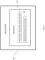
- Fig. 2 is a block diagram of a processor of the system of Fig. 1 .
- the medical procedure system 20 is typically used during an invasive and/or investigative procedure on a nasal sinus or another body part (such as the brain or heart) of a patient 22.
- a magnetic field radiation assembly 24 may be positioned behind and/or around the head of the patient 22, for example by fixing the assembly 24 to a bed 23 upon which the patient 22 is lying.
- the magnetic field radiation assembly 24 in the pictured example comprises five magnetic field radiators 26, which are fixed in a horseshoe shaped frame, the frame being positioned beneath or around the patient 22 so that the magnetic field radiators 26 surround the head of the patient 22.
- the magnetic field radiators 26 are configured to radiate alternating magnetic fields at respective frequencies into a region 30 where the body part is located, in proximity to the magnetic field radiation assembly 24 and which includes the head of patient 22.
- the alternating magnetic fields induce signals in position-tracking transducers 32.
- the position-tracking transducers 32 are shown disposed on a medical instrument 28 in order to track a position of the medical instrument 28.
- the medical instrument 28 may include an inflatable balloon 60.
- the medical instrument 28 may include any one or more of the following, a probe for inserting into the body-part, an endoscope, and/or a surgical tool such as an ENT tool, suction tool, microdebrider, shaver, and/or grasper.
- the position of a distal end 62 of the medical instrument 28 may be tracked using a position-tracking sub-system 64, which tracks position and orientation coordinates of the position-tracking transducers 32 fitted at the distal end 62.
- the position-tracking transducers 32 are configured to output signals that are indicative of the position of the transducers 32.
- the signals are processed by the position-tracking sub-system 64 running on processor 38 to track the position of the distal end 62 of the medical instrument 28.
- the position-tracking sub-system 64 is a magnetic tracking sub-system
- the position-tracking transducers 32 includes at least one coil, and typically two or three orthogonally placed coils.
- the position-tracking sub-system 64 may be an electrically-based tracking sub-system using multiple head surface electrodes to track the position of the medical instrument 28 based on a signal emitted by at least one electrode (comprised in the position-tracking transducer 32) of the medical instrument 28.
- the position-tracking sub-system 64 may be implemented using any suitable location tracking sub-system, for example, but not limited to, an ultrasound-based tracking system where the position-tracking transducers 32 includes at least one ultrasound transducer.
- a physician 54 advances the distal end 62 of the medical instrument 28 in a body-part, described in more detail below.
- position-tracking transducers 32 are affixed to the medical instrument 28, and determination of the location and orientation of the position-tracking transducers 32 enables tracking the location and orientation of the distal end 62 (or other location) of the medical instrument 28, that may be reversibly inserted into a body-part of the patient 22 (the living subject).
- the Carto ® system produced by Biosense Webster of 33 Technology Drive, Irvine, CA 92618 USA, uses a tracking system similar to that described herein for finding the location and orientation of a coil in a region irradiated by magnetic fields.
- Elements of system 20, including radiators 26, may be controlled by the processor 38, which comprises a processing unit communicating with one or more memories 42.
- the elements may be connected by cables to the processor 38, for example, radiators 26 may be connected by a cable 58 to the processor 38.
- the elements may be coupled wirelessly to the processor 38.
- the processor 38 may be mounted in a console 50, which comprises operating controls 51 that typically include a keypad and/or a pointing device such as a mouse or trackball.
- the console 50 also connects to other elements of the medical procedure system 20, such as a proximal end 52 of the medical instrument 28 via a cable 19.
- a physician 54 uses the operating controls 51 to interact with the processor 38 while performing the procedure, and the processor 38 may present results produced by system 20 on a display 56.
- CT images of the patient 22 are acquired prior to performing the medical procedure.
- the CT images are stored in the memory 42 for subsequent retrieval by the processor 38.
- the display 56 is shown displaying a view 59 of a previous CT scan (or other suitable scan) which may be used as an aid for the physician 54 to guide the medical instrument 28 in the body-part.
- the CT images may be registered with the magnetic coordinate system so that a representation of the medical instrument 28 may be displayed with the CT images on the display 56.
- processor 38 may be combined in a single physical component or, alternatively, implemented using multiple physical components. These physical components may comprise hard-wired or programmable devices, or a combination of the two. In some embodiments, at least some of the functions of the processor may be carried out by a programmable processor under the control of suitable software. This software may be downloaded to a device in electronic form, over a network, for example. Alternatively, or additionally, the software may be stored in tangible, non-transitory computer-readable storage media, such as optical, magnetic, or electronic memory.
- the medical procedure system 20 may also include a fluoroscope 40 for capturing fluoroscopic images.
- the medical procedure system 20 also includes a registration sub-system 44 running on the processor 38.
- the fluoroscope 40 and the registration sub-system 44 are described in more detail below with reference to Figs. 7-14 .
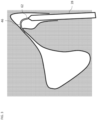
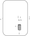
- Fig. 3 is a schematic view of the medical instrument 28 of the system 20 of Fig. 1 being inserted into a body-part of a living subject.
- the distal end 62 of the medical instrument 28 is shown being inserted into a sinus cavity of the patient 22.
- Fig. 3 shows that the medical instrument 28 includes a guide 46.
- the guide 46 may be fixed in multiple configurations ranging from straight to a number of curved formations.
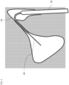
- Fig. 4 is a schematic view of the medical instrument 28 of Fig. 3 showing a guidewire 48 of the medical instrument 28 being extended into the body-part.
- the guidewire 48 is extended from within the guide 46 into the body-part.
- the guidewire 48 generally extends in the direction in which the distal end of the guide 46 was fixed.
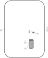
- Fig. 5 is a schematic view of a balloon device 66 of the medical instrument 28 being extended over the guidewire 48 of Fig. 4 .
- the balloon device 66 is shown with its balloon deflated.
- the balloon device 66 is described in more detail with reference to Figs. 6 and 7 below.
- Fig. 6 is a schematic view of the inflatable balloon 60 of the balloon device 66 of Fig. 5 being inflated.
- the inflatable balloon 60 may be inflated for any suitable medical procedure.
- the inflatable balloon 60 is inflated to perform a sinus dilation.
- the inflatable balloon 60 may be inflated using any suitable method for example, using air or a liquid such as saline.
- a suitable base design for the medical instrument 28 may be based on the RELIEVA SCOUT ® Multi-Sinus Dilation System produced by Acclarent, Inc., of Irvine, California, USA.
- the medical instrument 28 has been described herein as an ENT tool with the inflatable balloon 60.
- the medical instrument 28 may be any suitable medical instrument for use in any suitable body-part of a living subject.
- FIG. 7 is a schematic view of the medical instrument 28 of Fig. 6 including cross-sectional views 72 of transducers 32 of the medical instrument 28.
- Fig. 7 includes two cross-sectional views 72, labeled 72-1 and 72-2. Both of the cross-sectional views 72-1 are longitudinal cross-sectional views, showing the various layers of the medical instrument 28.
- the medical instrument 28 includes two position-tracking transducers 32 (labeled 32-1 and 32-2).
- the position-tracking transducer 32-1 may be a coil disposed coaxially with a shaft 68 of the medical instrument 28.
- the position-tracking transducer 32-2 which may be a coil, is disposed orthogonally to the position-tracking transducer 32-1.
- the position-tracking transducers 32-1, 32-2 together provide signals which may be used to compute a location and orientation including roll of the distal end 62 of the medical instrument 28.
- the position-tracking transducers 32 are shown as being disposed at a distal end of the inflatable balloon 60. In some embodiments, the position-tracking transducers 32 may be disposed at any suitable location on the medical instrument 28, for example, any suitable location of the shaft 68.
- the medical instrument 28 includes a radiopaque marker 70 disposed on the shaft 68.
- the radiopaque marker 70 includes a radiopaque cylinder as shown in Fig. 7 .
- the position-tracking transducer 32-1 is a coil, which is wound on the radiopaque cylinder.
- the medical instrument 28 also includes a radiopaque marker 74 disposed on an element (e.g., comprised in the inflatable balloon 60) of the distal end 62 that is configured to extend away from the axis of the shaft 68.
- a radiopaque marker 74 disposed on an element (e.g., comprised in the inflatable balloon 60) of the distal end 62 that is configured to extend away from the axis of the shaft 68.
- the radiopaque markers 70, 74 may be comprised of any suitable radiopaque material, for example, but not limited to, stainless steel or iron, which is suitably coated with a biocompatible material.
- the cross-sectional views 72-1, 72-1 shows that the guidewire 48 is disposed in the guide 46, and the guide 46 is surrounded by an inner layer 76 and an outer layer 78 of the balloon device 66 with the position-tracking transducers 32 sandwiched between the inner layer 76 and the outer layer 78.
- the cross-sectional view 72-1 shows radiopaque marker 70 (e.g., the radiopaque cylinder) surrounding the inner layer 76 with the coil of the position-tracking transducer 32-1 being wound on the radiopaque marker 70 coaxially with the shaft 68.
- the cross-sectional view 72-2 shows the coil of the position-tracking transducer 32-2 wound orthogonally to the coil of the position-tracking transducer 32-1
- the radiopaque marker 70 may be conveniently disposed in the same location as the position-tracking transducer 32-1 for easier computation of the registration described below.
- the position-tracking transducer 32-1 may be disposed in a different location from the radiopaque marker 70 and compensation between the given spatial relationship between the radiopaque marker 70 and the position-tracking transducer 32-1 is taken into account when performing the registration computations.
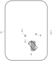
- Fig. 8 is a schematic view a user interface screen 80 including a captured fluoroscopic image 82 and graphical representations 84 (labeled 84-1 and 84-2) indicative of computed positions of the distal end 62 of the medical instrument 28.
- the captured fluoroscopic image 82 includes a marker-image 86 of the radiopaque marker 70 and a marker-image 88 of the radiopaque marker 74.
- the positioning of the graphical representation 84-1 in the user interface screen 80 corresponds to a computed location and orientation of the radiopaque marker 70 based on the signals provided by the position-tracking transducer 32-1.
- the positioning of the graphical representation 84-2 in the user interface screen 80 corresponds to a computed location of the radiopaque marker 74 based on the signals provided by the position-tracking transducer 32-2.
- the location of the radiopaque marker 74 may be computed based on a position around a circumference of the inflatable balloon 60 according to the computed roll of the position-tracking transducer 32-2 wherein the circumference also passes through the radiopaque marker 74.
- the physician 54 manipulates the graphical representations 84 using the operating controls 51 so that the graphical representation 84-1 and the graphical representation 84-2 are aligned with the marker-image 86 and the marker-image 88, respectively.
- the physician 54 may manipulate the graphical representations 84 by moving them across the user interface screen 80 in any suitable direction (up, down, left, right, diagonal etc.), moving them backwards, moving them forwards, and changing the orientation and rotation (roll) of the graphical representations 84.
- the graphical representations 84 correspond to different positions (e.g., the radiopaque marker 70 and the radiopaque marker 74) on the same item (e.g., the medical instrument 28), the graphical representations 84 are automatically moved together maintaining a same spatial relationship between the graphical representations 84. Nevertheless, it may be more intuitive for the physician 54 to try to align the cylinders (e.g., the graphical representation 84-1 with the marker-image 86) initially and then align the graphical representation 84-2 with the marker-image 88 afterwards.
- the physician 54 may try to align the cylinders (e.g., the graphical representation 84-1 with the marker-image 86) initially and then align the graphical representation 84-2 with the marker-image 88 afterwards.
- Fig. 9 is a schematic view of the user interface screen 80 of Fig. 8 after an initial user alignment of the graphical representations 84.
- Fig 9 shows that the graphical representations 84 have been moved closer to the marker-image 86 and the marker-image 88.
- FIG. 10 is a schematic view of the user interface screen 80 of Fig. 9 after a further user alignment of the graphical representations 84.
- Fig. 10 shows that the graphical representation 84-1 has been rotated clockwise and is almost aligned with the marker-image 86, but the graphical representation 84-2 is still misaligned with the marker-image 88.
- Fig. 11 is a schematic view of the user interface screen80 of Fig. 10 after yet further user alignment of the graphical representations 84.
- the graphical representations 84 have been rotated around the axis of the graphical representation 84-1 until the graphical representation 84-2 is almost aligned with the marker-image 88.
- the user alignment inputs are used to register the coordinate frame of the fluoroscope 40 with the coordinate frame of the position-tracking sub-system 64 ( Fig. 2 ).
- Fig. 12 is a flowchart 90 including exemplary steps in a registration method for use in the system 20 of Fig. 1 .
- the position-tracking sub-system 64 ( Fig. 2 ) is configured to compute (block 92) a position including at least one location and an orientation (including roll) of the distal end 62 of the medical instrument 28 in a position-tracking sub-system coordinate frame responsively to the position signals provided by the position-tracking transducers 32 ( Fig. 7 ).
- the position tracking sub-system 64 is configured to compute: a first position including a first location and an orientation (e.g., of the radiopaque marker 70) of the distal end 62 of the medical instrument 28 in the position-tracking sub-system coordinate frame responsively to the position signal provided by the position-tracking transducer 32-1; and a second position including a second location (e.g., of the radiopaque marker 74) of the distal end 62 of the medical instrument 28 in the position-tracking sub-system coordinate frame responsively to the position signal provided by the position-tracking transducer 32-2.
- the fluoroscope 40 is introduced and is configured to capture (block 94) fluoroscopic images of an interior of the body part and the radiopaque markers 70, 74 of the medical instrument 28 over time.
- the registration sub-system 44 is configured to render (block 96), to the display 56, the captured fluoroscopic images including the marker-image 86 of the radiopaque marker 70 and the marker-image 88 of the radiopaque marker 74, and superimpose over the fluoroscopic images, the graphical representations 84 at positions indicative of the computed position(s) of the distal end 62 (e.g., the graphical representation 84-1 at the first computed position and the graphical representations 84-2 at the second computed position).
- the registration sub-system 44 is configured to receive (block 98) user-alignment input aligning the respective graphical representations 84 with the respective ones of the marker-images 86, 88 (e.g., aligning the graphical representation 84-1 with the marker-image 86 and the graphical representation 84-2 with the marker-image 88.
- the registration sub-system 44 is configured to move (block 100) the graphical representations 84 with respect to the marker-images 86, 88 on the user interface screen 80 ( Figs. 8-11 ) according to the received user-alignment input.
- the steps of blocks 98 and 100 may repeated to allow for multiple updates to the movement of the graphical representations 84 on the user interface screen 80.
- the registration sub-system 44 is configured to register (block 102) the position-tracking sub-system coordinate frame with a coordinate frame of the fluoroscope 40 responsively to the received user-alignment input which brought the graphical representations 84 from their original position to their final position aligned with the marker-images 86, 88.
- the processor 38 is configured to render to the display 56 the fluoroscopic images with a representation of the medical instrument 28 thereon.
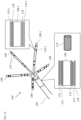
- the multi-prong probe 104 includes a shaft 106 and multiple prongs 108, each of the prongs 108 including a plurality of electrodes 110. Only some of the electrodes 110 have been labeled for the sake of simplicity.
- An example of the multi-prong probe 104 is the CARTO PENTARAY ® catheter produced by Biosense Webster of 33 Technology Drive, Irvine, CA 92618 USA.
- the multi-prong probe 104 includes a coil 112 wound on a radiopaque cylinder marker 114 which is disposed on the shaft 106 and is coaxial with the shaft 106.
- the coil 112 is covered with an outer layer 116.
- the coil 112 is configured as a position-tracking transducer and provides a position signal to the position-tracking sub-system 64 ( Fig. 2 ) in order to compute a location and orientation of the radiopaque cylinder 114.
- One of the electrodes 110, an electrode 110-1, of one of the prongs 108, a prong 108-1 is disposed over a radiopaque layer marker 118 over the prong 108-1 and is therefore co-located with the radiopaque layer marker 118.
- the prong 108-1 is an elongated element which is configured to extend away from the axis of the shaft 106.
- the electrode 110-1 may be used as a position-tracking transducer to provide a position signal to the position-tracking sub-system 64 in order to compute a position (e.g., location) of the radiopaque layer 118 which allows a roll of the multi-prong probe 104 to be registered.
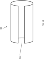
- Fig. 14 is a schematic view of an alternative radiopaque marker 120 for use in the system 20 of Fig. 1 .
- the single radiopaque marker 120 replaces the cylindrical radiopaque marker of Fig. 7 , and may be used to align location, orientation including roll.
- the single radiopaque marker 120 may include a cylinder with a longitudinal gap 122.
- a cylinder with a similarly sized longitudinal gap defined by a location and orientation (including roll) computed from signals provided by the coaxial coil 32-1 ( Fig. 7 ) and the orthogonally placed coil 32-2 ( Fig. 7 ) is superimposed over one of the fluoroscopic images in the user interface screen 80 ( Figs. 8-11 ).
- the physician 54 then manipulates the superimposed cylinder with respect to the marker-image of the radiopaque cylinder in order to align the cylinders including the longitudinal gaps of the cylinders.
- the user alignment input defines the differences between the fluoroscope coordinate frame and the position-tracking sub-system coordinate frame with respect to location and orientation including roll. The user alignment input is then used to register the two coordinate frames with each other.
Landscapes
- Health & Medical Sciences (AREA)
- Life Sciences & Earth Sciences (AREA)
- Engineering & Computer Science (AREA)
- Surgery (AREA)
- Medical Informatics (AREA)
- Public Health (AREA)
- Veterinary Medicine (AREA)
- Biomedical Technology (AREA)
- Heart & Thoracic Surgery (AREA)
- Molecular Biology (AREA)
- Animal Behavior & Ethology (AREA)
- General Health & Medical Sciences (AREA)
- Nuclear Medicine, Radiotherapy & Molecular Imaging (AREA)
- Pathology (AREA)
- Physics & Mathematics (AREA)
- Biophysics (AREA)
- Oral & Maxillofacial Surgery (AREA)
- Radiology & Medical Imaging (AREA)
- Human Computer Interaction (AREA)
- High Energy & Nuclear Physics (AREA)
- Optics & Photonics (AREA)
- Robotics (AREA)
- Dentistry (AREA)
- Otolaryngology (AREA)
- Pulmonology (AREA)
- Gynecology & Obstetrics (AREA)
- Apparatus For Radiation Diagnosis (AREA)
- Magnetic Resonance Imaging Apparatus (AREA)
Claims (12)
- System für medizinischen Eingriff (20), umfassend:ein medizinisches Instrument (28), das dazu ausgelegt ist, in einen Körperteil eines lebenden Subjekts eingeführt zu werden, und umfasst:Positionsverfolgungswandler (32), die zum Bereitstellen von Positionssignalen ausgelegt sind; einen Schaft (68);ein distales Ende (62); und mindestens einen röntgenstrahlenundurchlässigen Marker (70);ein Positionsverfolgungssubsystem (64), das dazu ausgelegt ist, in Reaktion auf die Positionssignale eine Position zu berechnen, die mindestens eine Lage und eine Orientierung des distalen Endes des medizinischen Instruments in einem Koordinatenrahmen des Positionsverfolgungssubsystems aufweist;ein Fluoroskop (40), das dazu ausgelegt ist, Durchleuchtungsbilder (82) eines Inneren des Körperteils und des mindestens einen röntgenstrahlenundurchlässigen Markers des medizinischen Instruments im Zeitablauf aufzunehmen;eine Anzeige (56); undein Registrierungssubsystem (44), das ausgelegt ist zum:Wiedergeben der aufgenommenen Durchleuchtungsbilder, die mindestens ein Markerbild (86) des mindestens einen röntgenstrahlenundurchlässigen Markers aufweisen, und mindestens einer grafischen Darstellung (84), die die berechnete Position des distalen Endes angibt, für die Anzeige;Empfangen einer Benutzerausrichtungseingabe, die die mindestens eine grafische Darstellung mit dem mindestens einen Markerbild ausrichtet; undRegistrieren des Koordinatenrahmens des Positionsverfolgungssubsystems mit einem Koordinatenrahmen des Fluoroskops in Reaktion auf die empfangene Benutzerausrichtungseingabe.
- System nach Anspruch 1, wobei:das distale Ende ein Element aufweist, das so ausgelegt ist, dass es sich von einer Achse des Schafts weg erstreckt;der mindestens eine röntgenstrahlenundurchlässige Marker aufweist:einen ersten röntgenstrahlenundurchlässigen Marker, der auf dem Schaft angeordnet ist; undeinen zweiten röntgenstrahlenundurchlässigen Marker, der auf dem Element angeordnet ist, das so ausgelegt ist, dass es sich von der Achse des Schafts weg erstreckt;das Positionsverfolgungssubsystem dazu ausgelegt ist, Folgendes zu berechnen:eine erste Position, die eine erste Lage und eine Orientierung des distalen Endes des medizinischen Instruments im Koordinatenrahmen des Positionsverfolgungssubsystems in Reaktion auf mindestens eines der Positionssignale aufweist; undeine zweite Position, die eine zweite Lage des distalen Endes des medizinischen Instruments im Koordinatenrahmen des Positionsverfolgungssubsystems in Reaktion auf mindestens eines der Positionssignale aufweist; unddas Registrierungssubsystem ausgelegt ist zum:Wiedergeben der aufgenommenen Durchleuchtungsbilder, die ein erstes Markerbild des ersten röntgenstrahlenundurchlässigen Markers, ein zweites Markerbild des zweiten röntgenstrahlenundurchlässigen Markers, eine erste grafische Darstellung, die die berechnete erste Position des distalen Endes angibt und eine zweite grafischen Darstellung aufweist, die die berechnete zweite Position des distalen Endes angibt, für die Anzeige;Empfangen einer Benutzerausrichtungseingabe, die die erste grafische Darstellung mit dem ersten Markerbild und die zweite grafische Darstellung mit dem zweiten Markerbild ausrichtet.
- System nach Anspruch 2, wobei die Positionsverfolgungswandler eine erste Spule aufweisen, die koaxial mit dem Schaft ist.
- System nach Anspruch 3, wobei der erste röntgenstrahlenundurchlässige Marker einen röntgenstrahlenundurchlässigen Zylinder aufweist.
- System nach Anspruch 4, wobei der erste Spule um den röntgenstrahlenundurchlässigen Zylinder gewickelt ist.
- System nach Anspruch 5, wobei die Positionsverfolgungswandler eine zweite Spule aufweisen, die orthogonal zur ersten Spule angeordnet ist.
- System nach Anspruch 3, wobei das Element, das so ausgelegt ist, dass es sich von der Achse des Schafts weg erstreckt, in einem aufblasbaren Ballon (60) umfasst ist.
- System nach Anspruch 7, wobei der erste röntgenstrahlenundurchlässige Marker einen röntgenstrahlenundurchlässigen Zylinder aufweist, die erste Spule um den röntgenstrahlenundurchlässigen Zylinder gewickelt ist und die Positionsverfolgungswandler eine zweite Spule umfassen, die orthogonal zur ersten Spule angeordnet ist.
- System nach Anspruch 3, wobei das Element, das so ausgelegt ist, dass es sich von der Achse des Schafts weg erstreckt, in einem länglichen Element (110) umfasst ist, das eine Elektrode (110) umfasst.
- System nach Anspruch 9, wobei die Positionsverfolgungswandler die Elektrode aufweisen.
- System nach Anspruch 10, wobei der zweite röntgenstrahlenundurchlässige Marker ortsgleich mit der Elektrode angeordnet ist.
- System nach Anspruch 1, wobei der mindestens eine röntgenstrahlenundurchlässige Marker einen Zylinder mit einem Längsspalt (82) aufweist,
Applications Claiming Priority (3)
| Application Number | Priority Date | Filing Date | Title |
|---|---|---|---|
| US201962852272P | 2019-05-23 | 2019-05-23 | |
| US16/797,619 US11589772B2 (en) | 2019-05-23 | 2020-02-21 | Probe with radiopaque tag |
| PCT/IB2020/053937 WO2020234668A1 (en) | 2019-05-23 | 2020-04-27 | Probe with radiopaque tag |
Publications (2)
| Publication Number | Publication Date |
|---|---|
| EP3972520A1 EP3972520A1 (de) | 2022-03-30 |
| EP3972520B1 true EP3972520B1 (de) | 2024-01-17 |
Family
ID=73457906
Family Applications (1)
| Application Number | Title | Priority Date | Filing Date |
|---|---|---|---|
| EP20727712.0A Active EP3972520B1 (de) | 2019-05-23 | 2020-04-27 | Sonde mit strahlenundurchlässigem etikett |
Country Status (6)
| Country | Link |
|---|---|
| US (2) | US11589772B2 (de) |
| EP (1) | EP3972520B1 (de) |
| JP (1) | JP7395618B2 (de) |
| CN (1) | CN113905685B (de) |
| IL (1) | IL288103B2 (de) |
| WO (1) | WO2020234668A1 (de) |
Families Citing this family (2)
| Publication number | Priority date | Publication date | Assignee | Title |
|---|---|---|---|---|
| US11589772B2 (en) | 2019-05-23 | 2023-02-28 | Biosense Webster (Israel) Ltd. | Probe with radiopaque tag |
| EP4193956A1 (de) * | 2021-12-10 | 2023-06-14 | Koninklijke Philips N.V. | Optische verfolgungsmarker |
Family Cites Families (20)
| Publication number | Priority date | Publication date | Assignee | Title |
|---|---|---|---|---|
| US5558091A (en) * | 1993-10-06 | 1996-09-24 | Biosense, Inc. | Magnetic determination of position and orientation |
| CA2250961C (en) * | 1997-02-14 | 2012-09-04 | Biosense, Inc. | X-ray guided surgical location system with extended mapping volume |
| DE19919907C2 (de) | 1999-04-30 | 2003-10-16 | Siemens Ag | Verfahren und Vorrichtung zur Katheter-Navigation in dreidimensionalen Gefäßbaum-Aufnahmen |
| US6484049B1 (en) * | 2000-04-28 | 2002-11-19 | Ge Medical Systems Global Technology Company, Llc | Fluoroscopic tracking and visualization system |
| JP5919862B2 (ja) * | 2012-02-13 | 2016-05-18 | ニプロ株式会社 | バルーンカテーテル |
| US20170258535A1 (en) * | 2012-06-21 | 2017-09-14 | Globus Medical, Inc. | Surgical robotic automation with tracking markers |
| US20180325610A1 (en) | 2012-06-21 | 2018-11-15 | Globus Medical, Inc. | Methods for indicating and confirming a point of interest using surgical navigation systems |
| US10441236B2 (en) | 2012-10-19 | 2019-10-15 | Biosense Webster (Israel) Ltd. | Integration between 3D maps and fluoroscopic images |
| US9949701B2 (en) * | 2013-02-14 | 2018-04-24 | Siemens Aktiengesellschaft | Registration for tracked medical tools and X-ray systems |
| US9782198B2 (en) * | 2013-03-28 | 2017-10-10 | Koninklijke Philips N.V. | Localization of robotic remote center of motion point using custom trocar |
| US10772489B2 (en) | 2014-07-09 | 2020-09-15 | Acclarent, Inc. | Guidewire navigation for sinuplasty |
| US9754372B2 (en) * | 2014-08-15 | 2017-09-05 | Biosense Webster (Israel) Ltd. | Marking of fluoroscope field-of-view |
| US9986983B2 (en) * | 2014-10-31 | 2018-06-05 | Covidien Lp | Computed tomography enhanced fluoroscopic system, device, and method of utilizing the same |
| US10952687B2 (en) * | 2015-03-06 | 2021-03-23 | University Of Rochester | Catheter detection, tracking and virtual image reconstruction |
| JP2018538019A (ja) * | 2015-10-14 | 2018-12-27 | サージヴィジオ | 医療画像に対してツールをナビゲートする蛍光ナビゲーションシステム |
| US10143526B2 (en) | 2015-11-30 | 2018-12-04 | Auris Health, Inc. | Robot-assisted driving systems and methods |
| US11026747B2 (en) * | 2017-04-25 | 2021-06-08 | Biosense Webster (Israel) Ltd. | Endoscopic view of invasive procedures in narrow passages |
| CN111095425B (zh) | 2017-07-03 | 2024-05-10 | 格罗伯斯医疗有限公司 | 术中对准评估系统和方法 |
| US10517612B2 (en) * | 2017-09-19 | 2019-12-31 | Biosense Webster (Israel) Ltd. | Nail hole guiding system |
| US11589772B2 (en) | 2019-05-23 | 2023-02-28 | Biosense Webster (Israel) Ltd. | Probe with radiopaque tag |
-
2020
- 2020-02-21 US US16/797,619 patent/US11589772B2/en active Active
- 2020-04-27 IL IL288103A patent/IL288103B2/en unknown
- 2020-04-27 EP EP20727712.0A patent/EP3972520B1/de active Active
- 2020-04-27 WO PCT/IB2020/053937 patent/WO2020234668A1/en not_active Ceased
- 2020-04-27 JP JP2021569451A patent/JP7395618B2/ja active Active
- 2020-04-27 CN CN202080038345.XA patent/CN113905685B/zh active Active
-
2022
- 2022-12-16 US US18/082,985 patent/US11883151B2/en active Active
Also Published As
| Publication number | Publication date |
|---|---|
| IL288103B1 (en) | 2024-02-01 |
| IL288103B2 (en) | 2024-06-01 |
| US20200367786A1 (en) | 2020-11-26 |
| EP3972520A1 (de) | 2022-03-30 |
| CN113905685A (zh) | 2022-01-07 |
| US11883151B2 (en) | 2024-01-30 |
| JP7395618B2 (ja) | 2023-12-11 |
| JP2022534696A (ja) | 2022-08-03 |
| CN113905685B (zh) | 2024-10-29 |
| US20230157568A1 (en) | 2023-05-25 |
| WO2020234668A1 (en) | 2020-11-26 |
| IL288103A (en) | 2022-01-01 |
| US11589772B2 (en) | 2023-02-28 |
Similar Documents
| Publication | Publication Date | Title |
|---|---|---|
| JP4822634B2 (ja) | 対象物の案内のための座標変換を求める方法 | |
| EP4287120A1 (de) | Führung während medizinischer eingriffe | |
| CN109414295B (zh) | 基于图像的导航的方法和装置 | |
| EP2722018B2 (de) | Integration zwischen 3D-Karten und fluoroskopischen Bildern | |
| US8320992B2 (en) | Method and system for superimposing three dimensional medical information on a three dimensional image | |
| US8694075B2 (en) | Intra-operative registration for navigated surgical procedures | |
| US8165660B2 (en) | System and method for selecting a guidance mode for performing a percutaneous procedure | |
| US6923768B2 (en) | Method and apparatus for acquiring and displaying a medical instrument introduced into a cavity organ of a patient to be examined or treated | |
| CN104274194B (zh) | 介入式成像系统 | |
| KR101458585B1 (ko) | 심혈관 진단 및 치료영상의 실시간 정합을 위한 방사선 불투과성 반구형 표지 | |
| EP4533394A1 (de) | Führung während medizinischer eingriffe | |
| JP7817270B2 (ja) | 経皮的介入におけるタイムリアルタイム誘導のための超音波プローブを備えたロボット | |
| US20090123046A1 (en) | System and method for generating intraoperative 3-dimensional images using non-contrast image data | |
| WO2008035271A2 (en) | Device for registering a 3d model | |
| US11883151B2 (en) | Probe with radiopaque tag | |
| CN117398182A (zh) | 用于监测医用对象的定向的方法和系统 | |
| CN118891018A (zh) | 基于mri的导航 | |
| EP3024408B1 (de) | Verhinderung chirurgischer eingriffe auf der falschen ebene | |
| EP4299029A2 (de) | Kegelstrahl-computertomographieintegration zur erzeugung eines navigationspfades zu einem ziel in der lunge und verfahren zur navigation zum ziel | |
| CN121746519A (zh) | 提供叠加数据集的方法、成像模态和计算机程序产品 |
Legal Events
| Date | Code | Title | Description |
|---|---|---|---|
| STAA | Information on the status of an ep patent application or granted ep patent |
Free format text: STATUS: UNKNOWN |
|
| STAA | Information on the status of an ep patent application or granted ep patent |
Free format text: STATUS: THE INTERNATIONAL PUBLICATION HAS BEEN MADE |
|
| PUAI | Public reference made under article 153(3) epc to a published international application that has entered the european phase |
Free format text: ORIGINAL CODE: 0009012 |
|
| STAA | Information on the status of an ep patent application or granted ep patent |
Free format text: STATUS: REQUEST FOR EXAMINATION WAS MADE |
|
| 17P | Request for examination filed |
Effective date: 20211117 |
|
| AK | Designated contracting states |
Kind code of ref document: A1 Designated state(s): AL AT BE BG CH CY CZ DE DK EE ES FI FR GB GR HR HU IE IS IT LI LT LU LV MC MK MT NL NO PL PT RO RS SE SI SK SM TR |
|
| RAP3 | Party data changed (applicant data changed or rights of an application transferred) |
Owner name: BIOSENSE WEBSTER (ISRAEL) LTD. |
|
| DAV | Request for validation of the european patent (deleted) | ||
| DAX | Request for extension of the european patent (deleted) | ||
| GRAP | Despatch of communication of intention to grant a patent |
Free format text: ORIGINAL CODE: EPIDOSNIGR1 |
|
| STAA | Information on the status of an ep patent application or granted ep patent |
Free format text: STATUS: GRANT OF PATENT IS INTENDED |
|
| INTG | Intention to grant announced |
Effective date: 20230817 |
|
| GRAS | Grant fee paid |
Free format text: ORIGINAL CODE: EPIDOSNIGR3 |
|
| GRAA | (expected) grant |
Free format text: ORIGINAL CODE: 0009210 |
|
| STAA | Information on the status of an ep patent application or granted ep patent |
Free format text: STATUS: THE PATENT HAS BEEN GRANTED |
|
| AK | Designated contracting states |
Kind code of ref document: B1 Designated state(s): AL AT BE BG CH CY CZ DE DK EE ES FI FR GB GR HR HU IE IS IT LI LT LU LV MC MK MT NL NO PL PT RO RS SE SI SK SM TR |
|
| REG | Reference to a national code |
Ref country code: GB Ref legal event code: FG4D |
|
| REG | Reference to a national code |
Ref country code: DE Ref legal event code: R096 Ref document number: 602020024503 Country of ref document: DE |
|
| REG | Reference to a national code |
Ref country code: CH Ref legal event code: EP |
|
| REG | Reference to a national code |
Ref country code: IE Ref legal event code: FG4D |
|
| REG | Reference to a national code |
Ref country code: LT Ref legal event code: MG9D |
|
| REG | Reference to a national code |
Ref country code: NL Ref legal event code: MP Effective date: 20240117 |
|
| REG | Reference to a national code |
Ref country code: AT Ref legal event code: MK05 Ref document number: 1650044 Country of ref document: AT Kind code of ref document: T Effective date: 20240117 |
|
| PG25 | Lapsed in a contracting state [announced via postgrant information from national office to epo] |
Ref country code: NL Free format text: LAPSE BECAUSE OF FAILURE TO SUBMIT A TRANSLATION OF THE DESCRIPTION OR TO PAY THE FEE WITHIN THE PRESCRIBED TIME-LIMIT Effective date: 20240117 |
|
| PG25 | Lapsed in a contracting state [announced via postgrant information from national office to epo] |
Ref country code: NL Free format text: LAPSE BECAUSE OF FAILURE TO SUBMIT A TRANSLATION OF THE DESCRIPTION OR TO PAY THE FEE WITHIN THE PRESCRIBED TIME-LIMIT Effective date: 20240117 |
|
| PG25 | Lapsed in a contracting state [announced via postgrant information from national office to epo] |
Ref country code: IS Free format text: LAPSE BECAUSE OF FAILURE TO SUBMIT A TRANSLATION OF THE DESCRIPTION OR TO PAY THE FEE WITHIN THE PRESCRIBED TIME-LIMIT Effective date: 20240517 |
|
| PG25 | Lapsed in a contracting state [announced via postgrant information from national office to epo] |
Ref country code: LT Free format text: LAPSE BECAUSE OF FAILURE TO SUBMIT A TRANSLATION OF THE DESCRIPTION OR TO PAY THE FEE WITHIN THE PRESCRIBED TIME-LIMIT Effective date: 20240117 |
|
| PG25 | Lapsed in a contracting state [announced via postgrant information from national office to epo] |
Ref country code: GR Free format text: LAPSE BECAUSE OF FAILURE TO SUBMIT A TRANSLATION OF THE DESCRIPTION OR TO PAY THE FEE WITHIN THE PRESCRIBED TIME-LIMIT Effective date: 20240418 |
|
| PG25 | Lapsed in a contracting state [announced via postgrant information from national office to epo] |
Ref country code: RS Free format text: LAPSE BECAUSE OF FAILURE TO SUBMIT A TRANSLATION OF THE DESCRIPTION OR TO PAY THE FEE WITHIN THE PRESCRIBED TIME-LIMIT Effective date: 20240417 Ref country code: HR Free format text: LAPSE BECAUSE OF FAILURE TO SUBMIT A TRANSLATION OF THE DESCRIPTION OR TO PAY THE FEE WITHIN THE PRESCRIBED TIME-LIMIT Effective date: 20240117 |
|
| PG25 | Lapsed in a contracting state [announced via postgrant information from national office to epo] |
Ref country code: ES Free format text: LAPSE BECAUSE OF FAILURE TO SUBMIT A TRANSLATION OF THE DESCRIPTION OR TO PAY THE FEE WITHIN THE PRESCRIBED TIME-LIMIT Effective date: 20240117 |
|
| PG25 | Lapsed in a contracting state [announced via postgrant information from national office to epo] |
Ref country code: AT Free format text: LAPSE BECAUSE OF FAILURE TO SUBMIT A TRANSLATION OF THE DESCRIPTION OR TO PAY THE FEE WITHIN THE PRESCRIBED TIME-LIMIT Effective date: 20240117 |
|
| PG25 | Lapsed in a contracting state [announced via postgrant information from national office to epo] |
Ref country code: RS Free format text: LAPSE BECAUSE OF FAILURE TO SUBMIT A TRANSLATION OF THE DESCRIPTION OR TO PAY THE FEE WITHIN THE PRESCRIBED TIME-LIMIT Effective date: 20240417 Ref country code: NO Free format text: LAPSE BECAUSE OF FAILURE TO SUBMIT A TRANSLATION OF THE DESCRIPTION OR TO PAY THE FEE WITHIN THE PRESCRIBED TIME-LIMIT Effective date: 20240417 Ref country code: LT Free format text: LAPSE BECAUSE OF FAILURE TO SUBMIT A TRANSLATION OF THE DESCRIPTION OR TO PAY THE FEE WITHIN THE PRESCRIBED TIME-LIMIT Effective date: 20240117 Ref country code: IS Free format text: LAPSE BECAUSE OF FAILURE TO SUBMIT A TRANSLATION OF THE DESCRIPTION OR TO PAY THE FEE WITHIN THE PRESCRIBED TIME-LIMIT Effective date: 20240517 Ref country code: HR Free format text: LAPSE BECAUSE OF FAILURE TO SUBMIT A TRANSLATION OF THE DESCRIPTION OR TO PAY THE FEE WITHIN THE PRESCRIBED TIME-LIMIT Effective date: 20240117 Ref country code: GR Free format text: LAPSE BECAUSE OF FAILURE TO SUBMIT A TRANSLATION OF THE DESCRIPTION OR TO PAY THE FEE WITHIN THE PRESCRIBED TIME-LIMIT Effective date: 20240418 Ref country code: FI Free format text: LAPSE BECAUSE OF FAILURE TO SUBMIT A TRANSLATION OF THE DESCRIPTION OR TO PAY THE FEE WITHIN THE PRESCRIBED TIME-LIMIT Effective date: 20240117 Ref country code: ES Free format text: LAPSE BECAUSE OF FAILURE TO SUBMIT A TRANSLATION OF THE DESCRIPTION OR TO PAY THE FEE WITHIN THE PRESCRIBED TIME-LIMIT Effective date: 20240117 Ref country code: BG Free format text: LAPSE BECAUSE OF FAILURE TO SUBMIT A TRANSLATION OF THE DESCRIPTION OR TO PAY THE FEE WITHIN THE PRESCRIBED TIME-LIMIT Effective date: 20240117 Ref country code: AT Free format text: LAPSE BECAUSE OF FAILURE TO SUBMIT A TRANSLATION OF THE DESCRIPTION OR TO PAY THE FEE WITHIN THE PRESCRIBED TIME-LIMIT Effective date: 20240117 |
|
| PG25 | Lapsed in a contracting state [announced via postgrant information from national office to epo] |
Ref country code: PL Free format text: LAPSE BECAUSE OF FAILURE TO SUBMIT A TRANSLATION OF THE DESCRIPTION OR TO PAY THE FEE WITHIN THE PRESCRIBED TIME-LIMIT Effective date: 20240117 Ref country code: PT Free format text: LAPSE BECAUSE OF FAILURE TO SUBMIT A TRANSLATION OF THE DESCRIPTION OR TO PAY THE FEE WITHIN THE PRESCRIBED TIME-LIMIT Effective date: 20240517 |
|
| PG25 | Lapsed in a contracting state [announced via postgrant information from national office to epo] |
Ref country code: SE Free format text: LAPSE BECAUSE OF FAILURE TO SUBMIT A TRANSLATION OF THE DESCRIPTION OR TO PAY THE FEE WITHIN THE PRESCRIBED TIME-LIMIT Effective date: 20240117 Ref country code: PT Free format text: LAPSE BECAUSE OF FAILURE TO SUBMIT A TRANSLATION OF THE DESCRIPTION OR TO PAY THE FEE WITHIN THE PRESCRIBED TIME-LIMIT Effective date: 20240517 Ref country code: PL Free format text: LAPSE BECAUSE OF FAILURE TO SUBMIT A TRANSLATION OF THE DESCRIPTION OR TO PAY THE FEE WITHIN THE PRESCRIBED TIME-LIMIT Effective date: 20240117 Ref country code: LV Free format text: LAPSE BECAUSE OF FAILURE TO SUBMIT A TRANSLATION OF THE DESCRIPTION OR TO PAY THE FEE WITHIN THE PRESCRIBED TIME-LIMIT Effective date: 20240117 |
|
| PG25 | Lapsed in a contracting state [announced via postgrant information from national office to epo] |
Ref country code: DK Free format text: LAPSE BECAUSE OF FAILURE TO SUBMIT A TRANSLATION OF THE DESCRIPTION OR TO PAY THE FEE WITHIN THE PRESCRIBED TIME-LIMIT Effective date: 20240117 |
|
| PG25 | Lapsed in a contracting state [announced via postgrant information from national office to epo] |
Ref country code: SM Free format text: LAPSE BECAUSE OF FAILURE TO SUBMIT A TRANSLATION OF THE DESCRIPTION OR TO PAY THE FEE WITHIN THE PRESCRIBED TIME-LIMIT Effective date: 20240117 |
|
| REG | Reference to a national code |
Ref country code: DE Ref legal event code: R097 Ref document number: 602020024503 Country of ref document: DE |
|
| PG25 | Lapsed in a contracting state [announced via postgrant information from national office to epo] |
Ref country code: EE Free format text: LAPSE BECAUSE OF FAILURE TO SUBMIT A TRANSLATION OF THE DESCRIPTION OR TO PAY THE FEE WITHIN THE PRESCRIBED TIME-LIMIT Effective date: 20240117 Ref country code: CZ Free format text: LAPSE BECAUSE OF FAILURE TO SUBMIT A TRANSLATION OF THE DESCRIPTION OR TO PAY THE FEE WITHIN THE PRESCRIBED TIME-LIMIT Effective date: 20240117 |
|
| PG25 | Lapsed in a contracting state [announced via postgrant information from national office to epo] |
Ref country code: SK Free format text: LAPSE BECAUSE OF FAILURE TO SUBMIT A TRANSLATION OF THE DESCRIPTION OR TO PAY THE FEE WITHIN THE PRESCRIBED TIME-LIMIT Effective date: 20240117 |
|
| PG25 | Lapsed in a contracting state [announced via postgrant information from national office to epo] |
Ref country code: SM Free format text: LAPSE BECAUSE OF FAILURE TO SUBMIT A TRANSLATION OF THE DESCRIPTION OR TO PAY THE FEE WITHIN THE PRESCRIBED TIME-LIMIT Effective date: 20240117 Ref country code: SK Free format text: LAPSE BECAUSE OF FAILURE TO SUBMIT A TRANSLATION OF THE DESCRIPTION OR TO PAY THE FEE WITHIN THE PRESCRIBED TIME-LIMIT Effective date: 20240117 Ref country code: RO Free format text: LAPSE BECAUSE OF FAILURE TO SUBMIT A TRANSLATION OF THE DESCRIPTION OR TO PAY THE FEE WITHIN THE PRESCRIBED TIME-LIMIT Effective date: 20240117 Ref country code: EE Free format text: LAPSE BECAUSE OF FAILURE TO SUBMIT A TRANSLATION OF THE DESCRIPTION OR TO PAY THE FEE WITHIN THE PRESCRIBED TIME-LIMIT Effective date: 20240117 Ref country code: DK Free format text: LAPSE BECAUSE OF FAILURE TO SUBMIT A TRANSLATION OF THE DESCRIPTION OR TO PAY THE FEE WITHIN THE PRESCRIBED TIME-LIMIT Effective date: 20240117 Ref country code: CZ Free format text: LAPSE BECAUSE OF FAILURE TO SUBMIT A TRANSLATION OF THE DESCRIPTION OR TO PAY THE FEE WITHIN THE PRESCRIBED TIME-LIMIT Effective date: 20240117 |
|
| PG25 | Lapsed in a contracting state [announced via postgrant information from national office to epo] |
Ref country code: MC Free format text: LAPSE BECAUSE OF FAILURE TO SUBMIT A TRANSLATION OF THE DESCRIPTION OR TO PAY THE FEE WITHIN THE PRESCRIBED TIME-LIMIT Effective date: 20240117 |
|
| PLBE | No opposition filed within time limit |
Free format text: ORIGINAL CODE: 0009261 |
|
| STAA | Information on the status of an ep patent application or granted ep patent |
Free format text: STATUS: NO OPPOSITION FILED WITHIN TIME LIMIT |
|
| PG25 | Lapsed in a contracting state [announced via postgrant information from national office to epo] |
Ref country code: MC Free format text: LAPSE BECAUSE OF FAILURE TO SUBMIT A TRANSLATION OF THE DESCRIPTION OR TO PAY THE FEE WITHIN THE PRESCRIBED TIME-LIMIT Effective date: 20240117 |
|
| REG | Reference to a national code |
Ref country code: CH Ref legal event code: PL |
|
| PG25 | Lapsed in a contracting state [announced via postgrant information from national office to epo] |
Ref country code: LU Free format text: LAPSE BECAUSE OF NON-PAYMENT OF DUE FEES Effective date: 20240427 |
|
| 26N | No opposition filed |
Effective date: 20241018 |
|
| REG | Reference to a national code |
Ref country code: BE Ref legal event code: MM Effective date: 20240430 |
|
| PG25 | Lapsed in a contracting state [announced via postgrant information from national office to epo] |
Ref country code: LU Free format text: LAPSE BECAUSE OF NON-PAYMENT OF DUE FEES Effective date: 20240427 |
|
| PG25 | Lapsed in a contracting state [announced via postgrant information from national office to epo] |
Ref country code: BE Free format text: LAPSE BECAUSE OF NON-PAYMENT OF DUE FEES Effective date: 20240430 |
|
| PG25 | Lapsed in a contracting state [announced via postgrant information from national office to epo] |
Ref country code: BE Free format text: LAPSE BECAUSE OF NON-PAYMENT OF DUE FEES Effective date: 20240430 Ref country code: CH Free format text: LAPSE BECAUSE OF NON-PAYMENT OF DUE FEES Effective date: 20240430 |
|
| PG25 | Lapsed in a contracting state [announced via postgrant information from national office to epo] |
Ref country code: IE Free format text: LAPSE BECAUSE OF NON-PAYMENT OF DUE FEES Effective date: 20240427 |
|
| PG25 | Lapsed in a contracting state [announced via postgrant information from national office to epo] |
Ref country code: SI Free format text: LAPSE BECAUSE OF FAILURE TO SUBMIT A TRANSLATION OF THE DESCRIPTION OR TO PAY THE FEE WITHIN THE PRESCRIBED TIME-LIMIT Effective date: 20240117 |
|
| PGFP | Annual fee paid to national office [announced via postgrant information from national office to epo] |
Ref country code: FR Payment date: 20250310 Year of fee payment: 6 |
|
| PGFP | Annual fee paid to national office [announced via postgrant information from national office to epo] |
Ref country code: GB Payment date: 20250306 Year of fee payment: 6 Ref country code: IT Payment date: 20250320 Year of fee payment: 6 |
|
| PGFP | Annual fee paid to national office [announced via postgrant information from national office to epo] |
Ref country code: DE Payment date: 20250305 Year of fee payment: 6 |
|
| PG25 | Lapsed in a contracting state [announced via postgrant information from national office to epo] |
Ref country code: CY Free format text: LAPSE BECAUSE OF FAILURE TO SUBMIT A TRANSLATION OF THE DESCRIPTION OR TO PAY THE FEE WITHIN THE PRESCRIBED TIME-LIMIT; INVALID AB INITIO Effective date: 20200427 |
|
| PG25 | Lapsed in a contracting state [announced via postgrant information from national office to epo] |
Ref country code: HU Free format text: LAPSE BECAUSE OF FAILURE TO SUBMIT A TRANSLATION OF THE DESCRIPTION OR TO PAY THE FEE WITHIN THE PRESCRIBED TIME-LIMIT; INVALID AB INITIO Effective date: 20200427 |