EP3972346B1 - Verbindungsumschaltungsverfahren und kommunikationsvorrichtung - Google Patents
Verbindungsumschaltungsverfahren und kommunikationsvorrichtung Download PDFInfo
- Publication number
- EP3972346B1 EP3972346B1 EP19941881.5A EP19941881A EP3972346B1 EP 3972346 B1 EP3972346 B1 EP 3972346B1 EP 19941881 A EP19941881 A EP 19941881A EP 3972346 B1 EP3972346 B1 EP 3972346B1
- Authority
- EP
- European Patent Office
- Prior art keywords
- link
- communication device
- communication
- relay
- present application
- Prior art date
- Legal status (The legal status is an assumption and is not a legal conclusion. Google has not performed a legal analysis and makes no representation as to the accuracy of the status listed.)
- Active
Links
Images
Classifications
-
- H—ELECTRICITY
- H04—ELECTRIC COMMUNICATION TECHNIQUE
- H04W—WIRELESS COMMUNICATION NETWORKS
- H04W76/00—Connection management
- H04W76/10—Connection setup
-
- H—ELECTRICITY
- H04—ELECTRIC COMMUNICATION TECHNIQUE
- H04W—WIRELESS COMMUNICATION NETWORKS
- H04W36/00—Hand-off or reselection arrangements
- H04W36/0005—Control or signalling for completing the hand-off
- H04W36/0011—Control or signalling for completing the hand-off for data sessions of end-to-end connection
- H04W36/0016—Hand-off preparation specially adapted for end-to-end data sessions
-
- H—ELECTRICITY
- H04—ELECTRIC COMMUNICATION TECHNIQUE
- H04W—WIRELESS COMMUNICATION NETWORKS
- H04W28/00—Network traffic management; Network resource management
- H04W28/02—Traffic management, e.g. flow control or congestion control
- H04W28/0231—Traffic management, e.g. flow control or congestion control based on communication conditions
- H04W28/0236—Traffic management, e.g. flow control or congestion control based on communication conditions radio quality, e.g. interference, losses or delay
-
- H—ELECTRICITY
- H04—ELECTRIC COMMUNICATION TECHNIQUE
- H04W—WIRELESS COMMUNICATION NETWORKS
- H04W36/00—Hand-off or reselection arrangements
- H04W36/03—Reselecting a link using a direct mode connection
- H04W36/033—Reselecting a link using a direct mode connection in pre-organised networks
-
- H—ELECTRICITY
- H04—ELECTRIC COMMUNICATION TECHNIQUE
- H04W—WIRELESS COMMUNICATION NETWORKS
- H04W40/00—Communication routing or communication path finding
- H04W40/02—Communication route or path selection, e.g. power-based or shortest path routing
- H04W40/12—Communication route or path selection, e.g. power-based or shortest path routing based on transmission quality or channel quality
-
- H—ELECTRICITY
- H04—ELECTRIC COMMUNICATION TECHNIQUE
- H04W—WIRELESS COMMUNICATION NETWORKS
- H04W40/00—Communication routing or communication path finding
- H04W40/02—Communication route or path selection, e.g. power-based or shortest path routing
- H04W40/22—Communication route or path selection, e.g. power-based or shortest path routing using selective relaying for reaching a BTS [Base Transceiver Station] or an access point
-
- H—ELECTRICITY
- H04—ELECTRIC COMMUNICATION TECHNIQUE
- H04L—TRANSMISSION OF DIGITAL INFORMATION, e.g. TELEGRAPHIC COMMUNICATION
- H04L45/00—Routing or path finding of packets in data switching networks
- H04L45/302—Route determination based on requested QoS
-
- H—ELECTRICITY
- H04—ELECTRIC COMMUNICATION TECHNIQUE
- H04W—WIRELESS COMMUNICATION NETWORKS
- H04W36/00—Hand-off or reselection arrangements
- H04W36/0005—Control or signalling for completing the hand-off
- H04W36/0055—Transmission or use of information for re-establishing the radio link
- H04W36/0079—Transmission or use of information for re-establishing the radio link in case of hand-off failure or rejection
-
- H—ELECTRICITY
- H04—ELECTRIC COMMUNICATION TECHNIQUE
- H04W—WIRELESS COMMUNICATION NETWORKS
- H04W88/00—Devices specially adapted for wireless communication networks, e.g. terminals, base stations or access point devices
- H04W88/02—Terminal devices
- H04W88/04—Terminal devices adapted for relaying to or from another terminal or user
Definitions
- Embodiments of the present application relate to the field of communication technologies, and more specifically, to a link switching method and communication device.
- Embodiments of present application provide a link switching method and a communication device, which are conducive to reducing latency in recovering of service transmission. It should be noted that embodiments of the invention are those whose scope is within that of the appended claims, and the implementations disclosed in this disclosure which do not fall under the scope of the appended claims are to be considered as examples for illustration.
- a second link between the two devices may be established, and the newly established second link is used for performing the service transmission, which is conducive to reducing latency in recovering of the service transmission.
- GSM Global System of Mobile communication
- CDMA Code Division Multiple Access
- WCDMA Wideband Code Division Multiple Access
- GPRS General Packet Radio Service
- LTE Long Term Evolution
- FDD Frequency Division Duplex
- TDD Time Division Duplex
- UMTS Universal Mobile Telecommunication System
- WiMAX Worldwide Interoperability for Microwave Access
- the technical solutions of the embodiments of the present application are applicable to various communication systems based on non-orthogonal multiple access technology, such as a Sparse Code Multiple Access (SCMA) system, and a Low Density Signature (LDS) system, etc.
- SCMA Sparse Code Multiple Access
- LDS Low Density Signature
- SCMA Sparse Code Multiple Access
- SCMA Sparse Code Multiple Access
- LDS Low Density Signature
- SCMA Sparse Code Multiple Access
- LDS Low Density Signature
- the technical solutions of the embodiments of the present application are applicable to a multicarrier transmission system employing non-orthogonal multiple access technology, such as an Orthogonal Frequency Division Multiplexing (OFDM) system, a Filter Bank Multi-Carrier (FBMC) system, a Generalized Frequency Division Multiplexing (GFDM) system, a Filtered-OFDM (F-OFDM) system, or the like using the non-orthogonal multiple access technology
- OFDM Orthogonal Frequency Division Multiplexing
- FBMC Filter Bank Multi-Carrier
- GFDM Generalized Frequency Division Multiplexing
- F-OFDM Filtered-OFDM
- the communication service between devices is mainly aimed at applications such as Augmented Reality (AR)/Virtual Reality (VR), games, etc., and has high requirements on service qualities such as speed, latency, packet loss rate and high-speed codec. For example, the rate of 10Gbps should be reached for VR games, and the packet loss rate should not exceed 10E-4.
- AR Augmented Reality
- VR Virtual Reality
- 10Gbps the rate of 10Gbps should be reached for VR games
- the packet loss rate should not exceed 10E-4.
- UEs of a session of the direct communication service between same devices may be considered to form a service application group, for example, a team in a game.
- D2D services are also referred to as Proximity-based Services (ProSe).
- ProSe Proximity-based Services
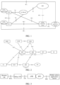
- FIG. 1 in a D2D communication architecture, because a UEA and a UEB provide related ProSe applications, their interfaces connected with a ProSe application server are PC1 interfaces, and an interface between the UE A and the UE B is a PC5, which is used for direct communication between UEs.
- the UE A and the UE B are connected with a ProSe functional entity through PC3 interfaces respectively, an interface between the ProSe functional entity and existing EPC is a PC4, and the interface between the ProSe functional entity and the ProSe application server is a PC2.
- the entire EPS includes an Evolved Universal Terrestrial Radio Access Network (E-UTRAN) and an Evolved PacketCore Networking (EPC), wherein the EPC includes a Home Subscriber Server (HSS), a Mobility Management Entity (MME), a Serving GPRS Support Node (SGSN), a Policy and Charging Rule Function (PCRF), a Serving Gateway (S-GW), a Packet Data Gateway (P-GW) and a Packet Data Network (PDN).
- the interface between the E-UTRAN and the EPC is an S1 interface, and the UE A and the UE B are connected with the E-UTRAN through LTE-Uu interfaces respectively.
- services between terminals may communicate directly through a PC5 interface, or the services of the terminals may be sent to the application server through Uu interfaces, and then the application server sends the services to a terminal of an opposite end.
- the terminal may directly send a service to the network, and their communication architecture is shown in FIG. 2 .
- the service may also be sent to the network by a relay, and their communication architecture is shown in FIG. 3 .
- the communication system may include an Access and Mobility Management Function (AMF), a Session Management Function (SMF), and a Policy Control Function (PCF), an Application Function (AF), a User Equipment (UE) (wherein the UE may also be referred to as a terminal device), an Access Network (an or Radio Access Network), RAN), a User Plane Function (UPF), a Data Network (DN), a Network Slice Selection Function (NSSF), an Authentication Server Function (AUSF) and a Unified Data Management (UDM).
- AMF Access and Mobility Management Function
- SMF Session Management Function
- PCF Policy Control Function
- AF Application Function
- UE User Equipment
- UPF User Plane Function
- DN Data Network
- NSSF Network Slice Selection Function
- AUSF Authentication Server Function
- UDM Unified Data Management
- the AMF is responsible for mobility management and is connected with the UE and the AN or the RAN.
- the SMF is responsible for session management and is connected with the UPF or the UDM.
- the PCF is responsible for policy control and may be connected with the SMF, the AF and the AMF.
- the UDM is responsible for subscription data management.
- N1 is an interface connecting a UE and the AMF
- N2 is an interface connecting the AMF and the AN or RAN
- N3 is an interface connecting the AN or RAN and the UPF
- N4 is an interface connecting the SMF and the UPF
- N5 is an interface connecting the PCF and the AF
- N6 is an interface connecting the UPF and the DN
- N7 is an interface connecting the SMF and the PCF
- N8 is an interface connecting the AMF and the UDM
- N9 is an interface connecting UPFs
- N10 is an interface connecting UDM and SMF
- N11 is an interface connecting the AMF and the SMF
- N12 is an interface connecting the AUSF and the AMF
- N13 is an interface connecting the AUSF and the UDM
- N14 is an interface connecting AMFs
- N15 is an interface connecting the AMF and the PCF
- N22 is an interface connecting the NSSF and the AMF
- Uu interface is an interface connecting the UE and the AN
- a remote UE communicates with an eNB through a relay UE, herein the relay UE is also referred to as a ProSe UE-to-network relay.
- the relay UE may be connected to the eNB through a Uu interface, and the remote UE may be connected to the relay UE through a PC5 interface.
- the relay UE may be within a coverage range and the remote UE may be outside the coverage range.
- the eNB is a part of the EPC, and the eNB may be connected to a public safety application server through a SGi interface.
- network devices in the foregoing various communication architectures may be devices that communicates with terminal devices (or referred to as communication terminals or terminals).
- a network device may provide communication coverage for a specific geographical area, and may communicate with terminal devices located within the coverage area.
- the network device may be a Base Transceiver Station (BTS) in a GSM system or a CDMA system, or a NodeB (NB) in a WCDMA system, or an Evolutional Node B (eNB or eNodeB) in an LTE system, or a radio controller in a Cloud Radio Access Network (CRAN), or the network device may be a mobile handover center, a relay station, an access point, a vehicle-mounted device, a wearable device, a hub, a switch, a bridge, a router, a network side device (gNB) in a 5G network, or a network device in a future evolved Public Land Mobile Network (PLMN), etc.
- BTS Base Transceiver Station
- NB NodeB
- the terminal devices in each of the above-mentioned communication architectures include, but are not limited to, User Equipment (UE), an access terminal, a user unit, a user station, a mobile site, a mobile station, a remote station, a remote terminal, a mobile device, a user terminal, a terminal, a wireless communications device, a user agent, or a user apparatus.
- UE User Equipment
- the access terminal may be a cellular phone, a cordless phone, a session initiation protocol (SIP) phone, a wireless local loop (WLL) station, a personal digital assistant (PDA), a handheld device with a wireless communication function, a computing device or another processing device connected to a wireless modem, an on-board device, a wearable device, a terminal device in a future 5G network, or a terminal device in a future evolved Public Land Mobile Network (PLMN), etc., which is not limited in the embodiments of the present invention.
- SIP session initiation protocol
- WLL wireless local loop
- PDA personal digital assistant
- PLMN Public Land Mobile Network
- the 5G system or the 5G network may also be referred to as a New Radio (NR) system or an NR network.
- NR New Radio
- FIG. 4 is a schematic block diagram of a link switching method 100 according to an embodiment of the present application. As shown in FIG. 4 , the method includes some or all of the following contents.
- the first communication device in a case that service transmission cannot be performed by using a first link between a first communication device and a second communication device, the first communication device establishes a second link between the first communication device and the second communication device.
- the first communication device performs the service transmission by using the second link, herein the communication devices on the first link and the second link are different.
- a terminal may have two links for selection during a communication with a terminal or during communication with a network respectively.
- the terminal may re-establish another new link, i.e., the second link, and use the second link for the communication.
- the method of an embodiment of the present application may be applied to a terminal-to-terminal communication, that is, the first communication device is a terminal device and the second communication device is a terminal device. It may also be applied to a terminal-to-network communication, that is, the first communication device is a terminal device and the second communication device is a network device, herein the communication devices on the first link and the second link are different.
- the failure of the transmission service by the first link may be considered as a certain communication device not good on the first link.
- the second link may be established by replacing or deleting the certain communication device, and then the second link may be used for communication.
- Terminal-to-terminal service a first link may be a direct link (i.e., using a PC5 interface) and communication devices on the first link only include a first terminal device and a second terminal device; a second link is a first access link (i.e., using a Uu interface) and communication devices on the second link include a network device besides the first terminal device and the second terminal device; or, the first link may be a first access link (i.e., using a Uu interface) and communication devices on the first link include a network device besides a first terminal device and a second terminal device, while the second link is a direct link (i.e., using a PC5 interface) and the communication devices on the second link only include the first terminal device and the second terminal device.
- a direct link i.e., using a PC5 interface
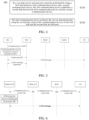
- FIG. 5 shows a schematic diagram of switching of a terminal-terminal service between a direct link and a access link according to an embodiment of the present application.
- a UE 1 and a UE 2 are communicating through a direct link.
- the UE 1 may detect that the direct link has failed or is about to fail, in other words, service transmission cannot be performed by the direct link.
- the UE 1 may establish an access link connection, that is, it may send a Non-Access Stratum (NAS) message to a Core Network (CN), herein the NAS message may include a service request or a Protocol Data Unit (PDU) session establishment request.
- NAS Non-Access Stratum
- CN Core Network
- the NAS message may include a service request or a Protocol Data Unit (PDU) session establishment request.
- PDU Protocol Data Unit
- the UE 1 may notify the UE 2, that is, send indication information to the UE 2, a main function of the indication information is to enable the UE 2 to start establishing an access link as well.
- the indication information may be at least one of the following information: the direct link has failed or is about to fail, the service link will or has been switched to the access link, and the direct link will or has been released.
- An embodiment of the present application does not limit the specific content of the indication information.
- the UE 1 and the UE 2 may perform negotiation of the link switching, and then the UE 1 may perform transmission of the terminal-to-terminal service with the UE 2 through the access link.
- the detection of the direct link may also be performed by the UE 2, that is, the UE 2 actively detects the direct link, and sends the indication information for starting the establishment of the access link to the UE 1 when the service transmission cannot be performed by the direct link. Furthermore, the UE 1 starts to establish the connection of the access link, and uses the access link to perform the transmission of the terminal-to-terminal service after performing the negotiation of the link switching with the UE 2.
- the UE 2 may also perform acts similar to those of the UE 1 until the communication between terminals is switched from the direct link to the access link. Regardless which terminal of the UE 1 or the UE 2 first detects that the service transmission cannot be performed by the direct link, it may indicate to the opposite terminal, for example, to indicate by a PC5-S Signaling or a PC5-Radio Resource Control (RRC) Signaling. After receiving the indication information, the opposite terminal may also start to establish the connection of the access link.
- RRC Radio Resource Control
- a negotiation process of link switching between the UE 1 and the UE 2 may include:
- the UE1 may send indication information to a UE 2, indicating the UE 2 to end sending and receiving data on the direct link, and/or indicating the UE 2 to send and receive data on the access link.
- the UE 2 may directly not send the data to the UE 1 through the direct link, nor receive the data from the UE 1 through the direct link.
- the UE 2 may further determine whether the access link of the UE 2 has been established at this time.
- the UE 2 may directly send the data to the UE 1 without the direct link and receive the data from the UE 1 without the direct link. Instead, the UE2 sends the data to and receives the data from the UE 1 through the access link. While if the establishment is not completed, the UE 2 may reply to the UE 1 to continue using the direct link. Optionally, the UE 2 may choose to continue to establish the access link at this time, or may stop establishing the access link. If the access link of the UE 2 is established successfully, the UE 1 may be informed to switch to the access link. Optionally, the indication information may also carry timer information, if the timer expires, the UE 2 will end receiving and sending the data on the direct link.
- the UE 2 may send and receive the data on the access link.
- the timer may be used when the UE 2 has not completed the establishment of the access link, if the timer expires, the access link will no longer be established, and if the timer does not expire, the establishment is continued.
- the timer may be started when the UE 2 receives the indication information carrying the timer information or when response information of the indication information is returned to the UE 1.
- a UE 2 may send indication information to a UE 1, indicating the UE 1 to end sending and receiving data on the direct link, and/or indicating the UE 1 to send and receive data on the access link.
- the UE 1 may directly not send the data to the UE 2 through the direct link, nor receive the data from the UE 2 through the direct link.
- the UE 1 may further determine whether the access link of the UE 1 has been established at this time.
- the UE 1 may directly send the data to the UE 2 without the direct link and receive the data of the UE 2 without the direct link. Instead, the UE1 sends the data to the UE 2 through the access link and receives the data of the UE 2 through the access link. While if the establishment is not completed, the UE 1 may reply to the UE 2 to continue using the direct link. Optionally, the UE 1 may choose to continue to establish the access link at this time, or may stop establishing the access link. If the access link of the UE 1 is established successfully, the UE 2 may be informed to switch to the access link.
- the indication information may also carry timer information, and the UE 1 will end receiving and sending the data on the direct link if the timer expires. Or, if the timer expires, the UE 1 may send and receive the data on the access link. Or, the timer may be used when the UE 1 has not completed the establishment of the access link, if the timer expires, the access link is no longer established, and if the timer does not expire, the establishment is continued. Optionally, the timer may be started when the UE 1 receives the indication information carrying the timer information or when response information of the indication information is returned to the UE 2.
- the UE 1 or the UE 2 may send the indication information to the opposite terminal.
- the indication information for ending sending or receiving the data on the direct link may also be indicated by a PC5-S Signaling or a PC5-Radio Resource Control (RRC) Signaling.
- RRC Radio Resource Control
- the data when the access link of the UE 1 is established, the data may be sent to the UE 2 through the access link.
- the UE2 uses the access link to send data.
- the UE2 uses the access link for performing service transmission.
- an application layer of the UE 2 receives the data from the UE 1, and the application layer of UE 2 notifies a lower layer, such as a PC5 layer or an RRC layer.
- data may be sent to the UE 1 through the access link.
- the UE1 uses the access link to send data.
- the UE2 uses the access link for performing service transmission.
- the UE 1 or the UE 2 may determine whether link quality of the direct link meets a preset condition. For example, it may be determined based on criteria of network configuration whether the service transmission can be performed by the direct link. Specifically, it may be determined based on a threshold of the link quality configured by the network, for example, a measured value of the link quality of the direct link is less than a threshold value. Or, it may be determined based on a specific application, Quality of Service (QoS) or PDU session, for example, whether it is less than a threshold value in the specific application, QoS or PDU session, herein the specific application, QoS or PDU session may be related to a service to be transmitted.
- QoS Quality of Service
- PDU session for example, whether it is less than a threshold value in the specific application, QoS or PDU session, herein the specific application, QoS or PDU session may be related to a service to be transmitted.
- the above description takes switching a direct link to a access link as an example, but an embodiment of the present application is also applicable to switching a access link to a direct link.
- the UE 1 or the UE 2 may establish a direct link and use the direct link for performing the service transmission. Further, the UE 1 or the UE 2 may indicate to an opposite terminal that the service transmission cannot be performed by the access link, or may also indicate the opposite terminal to end sending or receiving data on the access link.
- the detailed description of this solution may refer to the above, and details will not be repeated here for brevity.
- FIG. 5 shows an example in which an RAN1 serves a UE1 and an RAN2 serves a UE2, and the UE1 and the UE2 may be served by the same RAN.
- Terminal-network service a first link is a relay link and communication devices on the first link include a remote terminal device, a network device and a relay terminal device, while a second link is a second access link and communication devices on the second link include the remote terminal device and the network device.
- a first link is a second access link and communication devices on the first link includes a remote terminal device and a network device
- a second link is a relay link and communication devices on the second link include the remote terminal device, the network device and a relay terminal device.
- FIG. 6 shows a schematic diagram of switching of a terminal-network service between a relay link and an access link according to a claimed embodiment of the present application.
- a UE 1 and a UE 2 are communicating through a relay link.
- the UE 1 may detect that the relay link has failed or is about to fail, in other words, the service transmission cannot be performed by the relay link.
- the UE 1 may establish an access link connection, that is, may send a Non-Access Stratum (NAS) message to a Core Network (CN), herein the NAS message may include a service request or a Protocol Data Unit (PDU) session establishment request.
- NAS Non-Access Stratum
- CN Core Network
- the NAS message may include a service request or a Protocol Data Unit (PDU) session establishment request.
- PDU Protocol Data Unit
- the relay link mainly includes the use of the PC5 interface and the use of the Uu interface shown in FIG. 3 .
- the remote UE may detect by itself that the direct link between itself and the relay UE has failed or is about to fail, that is, the service transmission cannot be performed, and the remote UE may consider that the service transmission cannot be performed by the relay link between itself and the network device (RAN), and then it may initiate the establishment of the access link to the CN.
- RAN network device
- the relay UE may detect that the service transmission cannot be performed by the direct link between the relay UE and the remote UE, and/or the service transmission cannot be performed by the access link between the relay UE and the network device (RAN), the relay UE may indicate to the remote UE that the relay link cannot transmit services, and then the remote UE may initiate the establishment of the access link to the CN.
- the relay UE may detect that the service transmission cannot be performed by the direct link between the relay UE and the remote UE, and/or the service transmission cannot be performed by the access link between the relay UE and the network device (RAN), the relay UE may indicate to the remote UE that the relay link cannot transmit services, and then the remote UE may initiate the establishment of the access link to the CN.
- RAN network device
- the way of determining that the service transmission cannot be performed by a relay link is similar to the way of determining that the service transmission cannot be performed by the direct link as described above, and details will not be repeated here.
- the remote UE When the remote UE initiates a connection establishment request of a access link, it may use the access link for performing service transmission after the establishment is completed. Further, the remote UE may also notify a network side to delete the connection of a relay link, or notify the relay UE to initiate a release request of the relay link. Optionally, the relay UE may also actively initiate a release request of a relay link.
- FIG. 7 is a schematic block diagram of a communication device 200 according to an embodiment of the present application.
- the communication device 200 is a first communication device and the communication device 400 includes a processing unit 210 and a transceiving unit 220.
- the processing unit 210 is configured to establish a second link between a first communication device and a second communication device in a case that service transmission cannot be performed by using a first link between the first communication device and the second communication device.
- the transceiving unit 220 is configured to perform the service transmission by using the second link, herein the communication devices on the first link and the second link are different.
- the first link is a direct link and communication devices on the first link include the first communication device and the second communication device
- the second link is a first access link and communication devices on the second link include the first communication device, the second communication device and a network device.
- the first link is a first access link and communication devices on the first link include the first communication device, the second communication device and a network device
- the second link is a direct link and communication devices on the second link include the first communication device and the second communication device.
- the transceiving unit is further configured to send first indication information to the second communication device in the case that the service transmission cannot be performed by using the first link, herein the first indication information is used for indicating the second communication device to establish the second link.
- the transceiving unit is further configured to receive the first indication information sent by the second communication device, in the case that the service transmission cannot be performed by using the first link, herein the processing unit is specifically configured to establish the second link in response to the first indication information.
- the transceiving unit is further configured to send second indication information to the second communication device in a case that the first communication device has completed the establishment of the second link, herein the second indication information is used for indicating the second communication device to end sending and receiving data on the first link, and/or the second indication information is used for indicating the second communication device to send and receive the data on the second link.
- the transceiving unit is further configured to receive the second indication information sent by the second communication device, herein the second indication information is used for indicating the first communication device to end sending and receiving data on the first link, and/or the second indication information is used for indicating the second communication device to send and receive the data on the second link; and the transceiving unit is specifically configured to perform the service transmission by using the second link in response to the second indication information.
- the second indication information is used for indicating to end sending and receiving data on the first link in a case that a first timer expires, and/or, the second indication information is used for indicating to send and receive data on the second link in the case that the first timer expires.
- the first timer is started when the second indication information is received or when response information of the second indication information is sent.
- the transceiving unit is specifically configured to perform the service transmission by using the second link in response to the data received on the second link.
- the first link is a relay link and communication devices on the first link include the first communication device, the second communication device and a relay device, and the second link is a second access link and communication devices on the second link include the first communication device and the second communication device; or, when the first communication device is a terminal device and the second communication device is a network device, the first link is a second access link and communication devices on the first link include the first communication device and the second communication device, and the second link is a relay link and communication devices on the second link include the first communication device, the second communication device and a relay device.
- the transceiving unit is further configured to receive third indication information sent by the relay device, herein the third indication information is used for indicating that the service transmission cannot be performed by the relay link.
- the transceiving unit is further configured to notify the network device to delete a relay link in the case that the first communication device performs the service transmission by using the second link; or indicate the relay device to send a release request of the relay link to the network device in the case that the first communication device performs the service transmission by using the second link.
- the processing unit is further configured to determine that the service transmission cannot be performed by the first link in a case that the link quality of the first link is sufficient low to meet a first condition.
- the processing unit is specifically configured to determine that the service transmission cannot be performed by the first link if a measured value of the link quality of the first link is less than a first threshold.
- the first threshold is configured by the network side or determined based on an application corresponding to the service to be transmitted, Quality of Service (QoS), or requirements in a Protocol Data Unit (PDU) session.
- QoS Quality of Service
- PDU Protocol Data Unit
- the communication device 200 may correspond to the first communication device in the method embodiments of the present application, and the above-mentioned and other operations and/or functions of various units in the communication device 200 are respectively for implementing the corresponding processes of the terminal device in the method shown in FIG. 4 , which will not be repeated here for the sake of brevity.
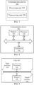
- FIG. 8 is a schematic diagram of a structure of a communication device 300 according to an embodiment of the present application.
- the communication device 300 shown in FIG. 8 includes a processor 310, herein the processor 310 may call and run a computer program from a memory to implement a method in an embodiment of the present application.
- the communication device 300 may further include a memory 320.
- the processor 310 may call and run a computer program from the memory 320 to implement a method in an embodiment of the present application.
- the memory 320 may be a separate device independent of the processor 310, or may be integrated in the processor 310.
- the communication device 300 may further include a transceiver 330, and the processor 310 may control the transceiver 330 to communicate with another device.
- the transceiver 730 may send information or data to another device or receive information or data sent by another device.
- the transceiver 330 may include a transmitter and a receiver.
- the transceiver 330 may further include antennas, a quantity of which may be one or more.
- the communication device 300 may specifically be the network device according to the embodiments of the present application, and the communication device 300 may implement the corresponding processes implemented by the network device in various methods in the embodiments of the present application, which will not be repeated here for brevity.
- the communication device 300 may be specifically the terminal device according to the embodiments of the present application, and the communication device 300 may implement the corresponding processes implemented by the terminal device in various methods in the embodiments of the present application, which will not be repeated here again for brevity.
- FIG. 9 is a schematic diagram of structure of a chip according to an embodiment of the present application.
- a chip 400 shown in FIG. 9 includes a processor 410 that may call and run a computer program from a memory to implement a method in an embodiment of the present application.
- the chip 400 may further include a memory 420.
- the processor 410 may call and run a computer program from the memory 420 to implement a method in an embodiment of the present application.
- the memory 420 may be a separate device independent of the processor 410, or may be integrated in the processor 410.
- the chip 400 may further include an input interface 430.
- the processor 410 may control the input interface 430 to communicate with another device or chip.
- the processor 410 may acquire information or data sent by another device or chip.
- the chip 400 may further include an output interface 440.
- the processor 410 may control the output interface 440 to communicate with another device or chip.
- the processor 410 may output information or data to another device or chip.
- the chip may be applied to a communication device of an embodiment of the present application, and the chip may implement corresponding processes implemented by the first communication device in various methods of the embodiments of the present application, which will not be repeated here for brevity.
- chip mentioned in the embodiments of the present application may also be referred to as a system-level chip, a system chip, a chip system, or a system on chip, etc.
- the processor in the embodiments of the present application may be an integrated circuit chip with a capability for processing signals.
- various acts of the method embodiments described above may be completed through an integrated logic circuit of hardware in a processor or instructions in a form of software.
- the above processor may be a general purpose processor, a Digital Signal Processor (DSP), an Application Specific Integrated Circuit (ASIC), a Field Programmable Gate Array (FPGA), or another programmable logic device, a discrete gate or a transistor logic device, or a discrete hardware component.
- DSP Digital Signal Processor
- ASIC Application Specific Integrated Circuit
- FPGA Field Programmable Gate Array
- the processor may implement various methods, acts, and logic block diagrams disclosed in the embodiments of the present application.
- the general purpose processor may be a microprocessor or the processor may be any conventional processor or the like.
- the acts of the methods disclosed in connection with the embodiments of the present application may be directly embodied by execution of a hardware decoding processor, or by execution of a combination of hardware and software modules in a decoding processor.
- the software modules may be located in a storage medium mature in the field, such as a Random Access Memory, a flash memory, a Read-Only Memory, a Programmable Read-Only Memory, or an electrically erasable programmable memory, or a register.
- the storage medium is located in a memory, and a processor reads information in the memory and completes the acts of the above methods in combination with its hardware.
- the memory in the embodiments of the present application may be a transitory memory or a non-transitory memory, or may include both transitory and non-transitory memory.
- the non-transitory memory may be a Read-Only Memory (ROM), a Programmable ROM (PROM), an Erasable PROM (EPROM), an Electrically EPROM (EEPROM), or a flash memory.
- the transitory memory may be a Random Access Memory (RAM) which serves as an external cache.
- RAMs such as a Static RAM (SRAM), a Dynamic RAM (DRAM), a Synchronous DRAM (SDRAM), a Double Data Rate SDRAM (DDR SDRAM), an Enhanced SDRAM (ESDRAM), a Synchlink DRAM (SLDRAM), and a Direct Rambus RAM (DR RAM).
- SRAM Static RAM
- DRAM Dynamic RAM
- SDRAM Synchronous DRAM
- DDR SDRAM Double Data Rate SDRAM
- ESDRAM Enhanced SDRAM
- SLDRAM Synchlink DRAM
- DR RAM Direct Rambus RAM
- the foregoing memories are examples for illustration and should not be construed as limitations.
- the memory in the embodiments of the present application may be a Static RAM (SRAM), a Dynamic RAM (DRAM), a Synchronous DRAM (SDRAM), a Double Data Rate SDRAM (DDR SDRAM), an Enhanced SDRAM (ESDRAM), a Synch link DRAM (SLDRAM), a Direct Rambus RAM (DR RAM), or the like. That is, the memories in the embodiments of the present application are intended to include, but are not limited to, these and any other suitable types of memories.
- the computer readable storage medium may be applied to a network device in an embodiment of the present application, and the computer program enables a computer to perform the corresponding processes implemented by the network device in various methods according to the embodiments of the present application, which will not be repeated here for brevity.
- the computer readable storage medium may be applied to a terminal device in an embodiment of the present application, and the computer program enables a computer to perform the corresponding processes implemented by the terminal device in various methods of the embodiments of the present application, which will not be repeated here for brevity.
- An embodiment of the present application further provides a computer program product, including computer program instructions.
- the computer program product may be applied to a network device in an embodiment of the present application, and the computer program instructions enable a computer to perform the corresponding processes implemented by the network device in various methods according to the embodiments of the present application, which will not be repeated here for brevity.
- the computer program product may be applied to a terminal device in an embodiment of the present application, and the computer program instructions enables a computer to perform the corresponding processes implemented by the terminal device in various methods of the embodiments of the present application, which will not be repeated here for brevity.
- An embodiment of the present application further provides a computer program.
- the computer program may be applied to a network device in an embodiment of the present application.
- the computer program When the computer program is run on a computer, the computer is enabled to perform the corresponding processes implemented by the network device in various methods according to the embodiments of the present application, which will not be repeated here for brevity.
- the computer program may be applied to a terminal device in an embodiment of the present application, and when the computer program is run on a computer, the computer is enabled to perform the corresponding processes implemented by the terminal device in various methods according to the embodiments of the present application, which will not be repeated here again for brevity.
- the units described as separated components may or may not be physically separated, and components shown as units may or may not be physical units, i.e., they may be located in one place or may be distributed over multiple network units. Some or all of the units may be selected according to practical needs to achieve the purpose of solutions of the embodiments.
- various functional units in various embodiments of the present application may be integrated in one processing unit, or various units may be physically present separately, or two or more units may be integrated in one unit.
- the functions may be stored in a computer readable storage medium if implemented in a form of a software functional unit and sold or used as a separate product.
- technical solutions of the present application in essence, or a part contributing to the existing art, or part of the technical solutions, may be embodied in a form of a software product stored in a storage medium, including several instructions for enabling a computer device (which may be a personal computer, a server, or a network device, etc.) to perform all or part of the acts of the methods described in various embodiments of the present application.
- the aforementioned storage medium includes: various media, such as a U disk, a mobile hard disk, a Read-Only Memory (ROM), a Random Access Memory (RAM), a magnetic disk, or an optical disk, etc., which may store program codes.
Landscapes
- Engineering & Computer Science (AREA)
- Computer Networks & Wireless Communication (AREA)
- Signal Processing (AREA)
- Mobile Radio Communication Systems (AREA)
Claims (5)
- Verfahren zur Verbindungsumschaltung, dadurch gekennzeichnet, dass es folgende Vorgänge umfasst:Aufbauen (S110), durch eine erste Kommunikationsvorrichtung, einer zweiten Verbindung zwischen der ersten Kommunikationsvorrichtung und einer zweiten Kommunikationsvorrichtung in einem Fall, in dem Dienstübertragung nicht unter Verwendung einer ersten Verbindung zwischen der ersten Kommunikationsvorrichtung und der zweiten Kommunikationsvorrichtung durchgeführt werden kann; undDurchführen (S120), durch die erste Kommunikationsvorrichtung, der Dienstübertragung unter Verwendung der zweiten Verbindung,wobei Kommunikationsvorrichtungen auf der ersten Verbindung und Kommunikationsvorrichtungen auf der zweiten Verbindung unterschiedlich sind; wobei die erste Kommunikationsvorrichtung ein Endgerät ist und die zweite Kommunikationsvorrichtung eine Netzvorrichtung ist, die erste Verbindung eine Relaisverbindung ist und die Kommunikationsvorrichtungen auf der ersten Verbindung die erste Kommunikationsvorrichtung, die zweite Kommunikationsvorrichtung und eine Relaisvorrichtung umfassen, und die zweite Verbindung eine zweite Zugangsverbindung ist und die Kommunikationsvorrichtungen auf der zweiten Verbindung die erste Kommunikationsvorrichtung und die zweite Kommunikationsvorrichtung umfassen; wobei das Verfahren ferner umfasst:
Benachrichtigen, durch die erste Kommunikationsvorrichtung, der Netzvorrichtung zum Löschen der Relaisverbindung in einem Fall, dass die erste Kommunikationsvorrichtung die Dienstübertragung unter Verwendung der zweiten Verbindung durchführt; wobei das Aufbauen (S110), durch eine erste Kommunikationsvorrichtung, einer zweiten Verbindung zwischen der ersten Kommunikationsvorrichtung und einer zweiten Kommunikationsvorrichtung in einem Fall, dass Dienstübertragung nicht unter Verwendung einer ersten Verbindung zwischen der ersten Kommunikationsvorrichtung und der zweiten Kommunikationsvorrichtung durchgeführt werden kann, umfasst:
Senden, durch die erste Kommunikationsvorrichtung, einer "Non-Access Stratum"-, NAS-, Meldung an ein "Core Network", CN, wobei die NAS-Nachricht eine Dienstanforderung oder eine "Protocol Data Unit"-, PDU-, Sitzungsaufbauanforderung umfasst. - Verfahren nach Anspruch 1, ferner umfassend:
Empfangen, durch die erste Kommunikationsvorrichtung, von dritten Anzeigeinformationen, die durch die Relaisvorrichtung gesendet werden, wobei die dritten Anzeigeinformationen verwendet werden, um anzuzeigen, dass die Dienstübertragung nicht durch die Relaisverbindung durchgeführt werden kann. - Kommunikationsvorrichtung (200), bei der es sich um eine erste Kommunikationsvorrichtung handelt, wobei die Kommunikationsvorrichtung umfasst:eine Verarbeitungseinheit (210), die dafür ausgelegt ist, eine zweite Verbindung zwischen einer ersten Kommunikationsvorrichtung und einer zweiten Kommunikationsvorrichtung in einem Fall aufzubauen, in dem Dienstübertragung nicht unter Verwendung einer ersten Verbindung zwischen der ersten Kommunikationsvorrichtung und der zweiten Kommunikationsvorrichtung durchgeführt werden kann; undeine Sende-Empfangseinheit (220), die dafür ausgelegt ist, die Dienstübertragung unter Verwendung der zweiten Verbindung durchzuführen,wobei Kommunikationsvorrichtungen auf der ersten Verbindung und Kommunikationsvorrichtungen auf der zweiten Verbindung unterschiedlich sind; wobei die erste Kommunikationsvorrichtung ein Endgerät ist und die zweite Kommunikationsvorrichtung eine Netzvorrichtung ist, die erste Verbindung eine Relaisverbindung ist und die Kommunikationsvorrichtungen auf der ersten Verbindung die erste Kommunikationsvorrichtung, die zweite Kommunikationsvorrichtung und eine Relaisvorrichtung umfassen, und die zweite Verbindung eine zweite Zugangsverbindung ist und die Kommunikationsvorrichtungen auf der zweiten Verbindung die erste Kommunikationsvorrichtung und die zweite Kommunikationsvorrichtung umfassen; wobei die Verarbeitungseinheit (210) ferner für folgenden Vorgang ausgelegt ist:
Benachrichtigen der Netzvorrichtung zum Löschen der Relaisverbindung in einem Fall, dass die erste Kommunikationsvorrichtung die Dienstübertragung unter Verwendung der zweiten Verbindung durchführt; wobei die Verarbeitungseinheit ferner für folgenden Vorgang ausgelegt ist:
Senden einer "Non-Access Stratum"-, NAS-, Meldung an ein "Core Network", CN, wobei die NAS-Nachricht eine Dienstanforderung oder eine "Protocol Data Unit"-, PDU-, Sitzungsaufbauanforderung umfasst. - Kommunikationsvorrichtung nach Anspruch 3, wobei die Sende-Empfangseinheit (220) ferner für folgenden Vorgang ausgelegt ist:
Empfangen von dritten Anzeigeinformationen, die durch die Relaisvorrichtung gesendet werden, wobei die dritten Anzeigeinformationen verwendet werden, um anzuzeigen, dass die Dienstübertragung nicht durch die Relaisverbindung durchgeführt werden kann. - Kommunikationsvorrichtung, umfassend: einen Prozessor und einen Speicher, wobei der Speicher dafür ausgelegt ist, ein Computerprogramm zu speichern, und der Prozessor dafür ausgelegt ist, das im Speicher gespeicherte Computerprogramm zum Durchführen des Verfahrens nach einem der Ansprüche 1 bis 2 aufzurufen und auszuführen.
Applications Claiming Priority (1)
| Application Number | Priority Date | Filing Date | Title |
|---|---|---|---|
| PCT/CN2019/101196 WO2021031022A1 (zh) | 2019-08-16 | 2019-08-16 | 链路切换的方法和通信设备 |
Publications (3)
| Publication Number | Publication Date |
|---|---|
| EP3972346A1 EP3972346A1 (de) | 2022-03-23 |
| EP3972346A4 EP3972346A4 (de) | 2022-05-18 |
| EP3972346B1 true EP3972346B1 (de) | 2025-05-14 |
Family
ID=74660423
Family Applications (1)
| Application Number | Title | Priority Date | Filing Date |
|---|---|---|---|
| EP19941881.5A Active EP3972346B1 (de) | 2019-08-16 | 2019-08-16 | Verbindungsumschaltungsverfahren und kommunikationsvorrichtung |
Country Status (4)
| Country | Link |
|---|---|
| US (1) | US20220110025A1 (de) |
| EP (1) | EP3972346B1 (de) |
| CN (1) | CN113632544A (de) |
| WO (1) | WO2021031022A1 (de) |
Families Citing this family (10)
| Publication number | Priority date | Publication date | Assignee | Title |
|---|---|---|---|---|
| WO2021134725A1 (zh) * | 2019-12-31 | 2021-07-08 | 华为技术有限公司 | 通信方法及装置 |
| CN111432469B (zh) * | 2020-03-05 | 2022-04-12 | 华为技术有限公司 | 一种通信方法及相关装置 |
| US11689957B2 (en) * | 2020-03-13 | 2023-06-27 | Qualcomm Incorporated | Quality of service support for sidelink relay service |
| US11825330B2 (en) | 2020-03-13 | 2023-11-21 | Qualcomm Incorporated | Techniques for quality of service support in sidelink communications |
| WO2022236632A1 (en) * | 2021-05-10 | 2022-11-17 | Lenovo (Beijing) Limited | Method and apparatus for ue-to-network relay handover |
| CN116156540A (zh) * | 2021-11-23 | 2023-05-23 | 大唐移动通信设备有限公司 | 层2测量方法、装置及存储介质 |
| CN116567589A (zh) * | 2022-01-28 | 2023-08-08 | 中国电信股份有限公司 | 近域通信转换到网络通信的方法、装置、设备及存储介质 |
| CN114698047B (zh) * | 2022-03-30 | 2024-08-27 | 深圳市信锐网科技术有限公司 | 一种数据传输方法、装置、设备及计算机可读存储介质 |
| CN117202405A (zh) * | 2022-05-31 | 2023-12-08 | 华为技术有限公司 | 一种补偿通信方法和系统 |
| CN118741647A (zh) * | 2023-03-31 | 2024-10-01 | 维沃移动通信有限公司 | 链路传输、信息配置方法、装置及通信设备 |
Citations (1)
| Publication number | Priority date | Publication date | Assignee | Title |
|---|---|---|---|---|
| US20160066289A1 (en) * | 2014-08-28 | 2016-03-03 | Qualcomm Incorporated | Hyperframe number desynchronization recovery mechanism |
Family Cites Families (12)
| Publication number | Priority date | Publication date | Assignee | Title |
|---|---|---|---|---|
| US8144597B2 (en) * | 2008-01-22 | 2012-03-27 | Rockstar Bidco L.P. | Path selection for a wireless system with relays |
| CN103442397B (zh) * | 2013-08-01 | 2016-04-27 | 西安交通大学 | Lte-a中继系统的基于辅助载波的协作切换方法 |
| KR102083322B1 (ko) * | 2013-08-22 | 2020-03-03 | 삼성전자주식회사 | 이동 통신 시스템에서 고립 사용자 단말기에 대한 디바이스-투-디바이스 통신 기반 서비스 제공 장치 및 방법 |
| US9585159B2 (en) * | 2014-12-19 | 2017-02-28 | Qualcomm Incorporated | Opportunistic dual-band relay |
| CN106162779B (zh) * | 2015-04-09 | 2020-06-05 | 上海诺基亚贝尔股份有限公司 | 用于保持用户设备的业务连续性的方法 |
| CN109328483A (zh) * | 2016-07-04 | 2019-02-12 | 华为技术有限公司 | 一种无线链路失败处理方法、相关设备及通信系统 |
| US20190320357A1 (en) * | 2016-12-05 | 2019-10-17 | Huawei Technologies Co., Ltd. | Information Transmission Method and Device |
| CN108282251B (zh) * | 2017-01-06 | 2021-03-16 | 腾讯科技(深圳)有限公司 | 一种链路调整方法、装置及服务器 |
| US10945179B2 (en) * | 2017-01-10 | 2021-03-09 | Huawei Technologies Co., Ltd. | Communication path switching method and device |
| US12538343B2 (en) * | 2018-09-26 | 2026-01-27 | Qualcomm Incorporated | Communication based on radio signal measurements |
| JP7226563B2 (ja) * | 2019-01-10 | 2023-02-21 | 富士通株式会社 | ページング機会の構成決定方法、装置及びシステム |
| WO2020209603A1 (ko) * | 2019-04-08 | 2020-10-15 | 엘지전자 주식회사 | 사이드링크 통신을 수행하는 방법 및 장치 |
-
2019
- 2019-08-16 EP EP19941881.5A patent/EP3972346B1/de active Active
- 2019-08-16 WO PCT/CN2019/101196 patent/WO2021031022A1/zh not_active Ceased
- 2019-08-16 CN CN201980094756.8A patent/CN113632544A/zh active Pending
-
2021
- 2021-12-17 US US17/644,871 patent/US20220110025A1/en not_active Abandoned
Patent Citations (1)
| Publication number | Priority date | Publication date | Assignee | Title |
|---|---|---|---|---|
| US20160066289A1 (en) * | 2014-08-28 | 2016-03-03 | Qualcomm Incorporated | Hyperframe number desynchronization recovery mechanism |
Also Published As
| Publication number | Publication date |
|---|---|
| EP3972346A4 (de) | 2022-05-18 |
| WO2021031022A1 (zh) | 2021-02-25 |
| CN113632544A (zh) | 2021-11-09 |
| EP3972346A1 (de) | 2022-03-23 |
| US20220110025A1 (en) | 2022-04-07 |
Similar Documents
| Publication | Publication Date | Title |
|---|---|---|
| EP3972346B1 (de) | Verbindungsumschaltungsverfahren und kommunikationsvorrichtung | |
| US11240699B2 (en) | Insufficient resources in the UE during PDU session establishment procedure | |
| KR102820754B1 (ko) | 비-3gpp 상의 ims 음성 세션을 3gpp 액세스로 이동시키기 위한 방안 | |
| WO2019196783A1 (en) | Handling qos flow without a mapping data radio bearer | |
| CN110149732B (zh) | 一种通信方法及无线通信装置 | |
| US20160338136A1 (en) | Method and Device for Processing Radio Link Failure | |
| EP4236424A1 (de) | Datenübertragungssteuerungsverfahren, vorrichtung und speichermedium | |
| KR101959937B1 (ko) | 무선 자원 제어(rrc) 접속 방법 및 장치 그리고 rrc 재접속 방법 및 장치 | |
| CN113273246B (zh) | 无线通信的方法、终端设备、接入网设备和核心网设备 | |
| WO2021203252A1 (zh) | 非激活态下的数据发送、接收方法及装置、用户设备 | |
| EP3952596B1 (de) | Informationsübertragungsverfahren und -einrichtung | |
| CN108366398A (zh) | 一种数据传输方法、网络设备及终端设备 | |
| WO2019105064A1 (en) | Method and apparatus for signal transmission, network equipment | |
| CN113261340B (zh) | 传输信息的方法、终端设备、基站和核心网设备 | |
| CN115244979A (zh) | 一种数据传输方法及装置、通信设备 | |
| EP3823387B1 (de) | Informationsanzeigeverfahren und -vorrichtung | |
| CN106060850B (zh) | 一种语音调度方法及装置 | |
| US12166634B2 (en) | Wireless communication method and terminal device | |
| CN114600548A (zh) | 一种链路切换方法及装置、通信设备 | |
| US11540252B2 (en) | Data transmission method, network device | |
| CN118140574A (zh) | 一种通信处理方法及装置、终端设备、接入网设备 | |
| US20250113270A1 (en) | Methods and apparatuses of a link management and mobility for ul aggregation | |
| CN120982202A (zh) | 用于侧行链路中继的方法及设备 | |
| CN116711453A (zh) | 用于处置数据传输的回退的方法及装置 | |
| CN118474912B (zh) | 一种通信方法和通信装置 |
Legal Events
| Date | Code | Title | Description |
|---|---|---|---|
| STAA | Information on the status of an ep patent application or granted ep patent |
Free format text: STATUS: THE INTERNATIONAL PUBLICATION HAS BEEN MADE |
|
| PUAI | Public reference made under article 153(3) epc to a published international application that has entered the european phase |
Free format text: ORIGINAL CODE: 0009012 |
|
| STAA | Information on the status of an ep patent application or granted ep patent |
Free format text: STATUS: REQUEST FOR EXAMINATION WAS MADE |
|
| 17P | Request for examination filed |
Effective date: 20211216 |
|
| AK | Designated contracting states |
Kind code of ref document: A1 Designated state(s): AL AT BE BG CH CY CZ DE DK EE ES FI FR GB GR HR HU IE IS IT LI LT LU LV MC MK MT NL NO PL PT RO RS SE SI SK SM TR |
|
| A4 | Supplementary search report drawn up and despatched |
Effective date: 20220420 |
|
| RIC1 | Information provided on ipc code assigned before grant |
Ipc: H04W 76/10 20180101ALI20220412BHEP Ipc: H04W 36/00 20090101ALI20220412BHEP Ipc: H04W 40/22 20090101AFI20220412BHEP |
|
| DAV | Request for validation of the european patent (deleted) | ||
| DAX | Request for extension of the european patent (deleted) | ||
| STAA | Information on the status of an ep patent application or granted ep patent |
Free format text: STATUS: EXAMINATION IS IN PROGRESS |
|
| 17Q | First examination report despatched |
Effective date: 20230120 |
|
| GRAP | Despatch of communication of intention to grant a patent |
Free format text: ORIGINAL CODE: EPIDOSNIGR1 |
|
| STAA | Information on the status of an ep patent application or granted ep patent |
Free format text: STATUS: GRANT OF PATENT IS INTENDED |
|
| RIC1 | Information provided on ipc code assigned before grant |
Ipc: H04W 76/10 20180101ALI20241118BHEP Ipc: H04W 36/00 20090101ALI20241118BHEP Ipc: H04W 40/22 20090101AFI20241118BHEP |
|
| RIC1 | Information provided on ipc code assigned before grant |
Ipc: H04W 76/10 20180101ALI20241204BHEP Ipc: H04W 36/00 20090101ALI20241204BHEP Ipc: H04W 40/22 20090101AFI20241204BHEP |
|
| INTG | Intention to grant announced |
Effective date: 20241216 |
|
| GRAS | Grant fee paid |
Free format text: ORIGINAL CODE: EPIDOSNIGR3 |
|
| GRAA | (expected) grant |
Free format text: ORIGINAL CODE: 0009210 |
|
| STAA | Information on the status of an ep patent application or granted ep patent |
Free format text: STATUS: THE PATENT HAS BEEN GRANTED |
|
| AK | Designated contracting states |
Kind code of ref document: B1 Designated state(s): AL AT BE BG CH CY CZ DE DK EE ES FI FR GB GR HR HU IE IS IT LI LT LU LV MC MK MT NL NO PL PT RO RS SE SI SK SM TR |
|
| REG | Reference to a national code |
Ref country code: GB Ref legal event code: FG4D |
|
| REG | Reference to a national code |
Ref country code: CH Ref legal event code: EP |
|
| REG | Reference to a national code |
Ref country code: DE Ref legal event code: R096 Ref document number: 602019070118 Country of ref document: DE |
|
| REG | Reference to a national code |
Ref country code: IE Ref legal event code: FG4D |
|
| REG | Reference to a national code |
Ref country code: NL Ref legal event code: MP Effective date: 20250514 |
|
| P01 | Opt-out of the competence of the unified patent court (upc) registered |
Free format text: CASE NUMBER: UPC_APP_5347_3972346/2025 Effective date: 20250829 |
|
| PG25 | Lapsed in a contracting state [announced via postgrant information from national office to epo] |
Ref country code: FI Free format text: LAPSE BECAUSE OF FAILURE TO SUBMIT A TRANSLATION OF THE DESCRIPTION OR TO PAY THE FEE WITHIN THE PRESCRIBED TIME-LIMIT Effective date: 20250514 Ref country code: PT Free format text: LAPSE BECAUSE OF FAILURE TO SUBMIT A TRANSLATION OF THE DESCRIPTION OR TO PAY THE FEE WITHIN THE PRESCRIBED TIME-LIMIT Effective date: 20250915 Ref country code: ES Free format text: LAPSE BECAUSE OF FAILURE TO SUBMIT A TRANSLATION OF THE DESCRIPTION OR TO PAY THE FEE WITHIN THE PRESCRIBED TIME-LIMIT Effective date: 20250514 |
|
| REG | Reference to a national code |
Ref country code: LT Ref legal event code: MG9D |
|
| PG25 | Lapsed in a contracting state [announced via postgrant information from national office to epo] |
Ref country code: NO Free format text: LAPSE BECAUSE OF FAILURE TO SUBMIT A TRANSLATION OF THE DESCRIPTION OR TO PAY THE FEE WITHIN THE PRESCRIBED TIME-LIMIT Effective date: 20250814 Ref country code: GR Free format text: LAPSE BECAUSE OF FAILURE TO SUBMIT A TRANSLATION OF THE DESCRIPTION OR TO PAY THE FEE WITHIN THE PRESCRIBED TIME-LIMIT Effective date: 20250815 |
|
| PG25 | Lapsed in a contracting state [announced via postgrant information from national office to epo] |
Ref country code: NL Free format text: LAPSE BECAUSE OF FAILURE TO SUBMIT A TRANSLATION OF THE DESCRIPTION OR TO PAY THE FEE WITHIN THE PRESCRIBED TIME-LIMIT Effective date: 20250514 Ref country code: PL Free format text: LAPSE BECAUSE OF FAILURE TO SUBMIT A TRANSLATION OF THE DESCRIPTION OR TO PAY THE FEE WITHIN THE PRESCRIBED TIME-LIMIT Effective date: 20250514 |
|
| REG | Reference to a national code |
Ref country code: AT Ref legal event code: MK05 Ref document number: 1795872 Country of ref document: AT Kind code of ref document: T Effective date: 20250514 |
|
| PG25 | Lapsed in a contracting state [announced via postgrant information from national office to epo] |
Ref country code: BG Free format text: LAPSE BECAUSE OF FAILURE TO SUBMIT A TRANSLATION OF THE DESCRIPTION OR TO PAY THE FEE WITHIN THE PRESCRIBED TIME-LIMIT Effective date: 20250514 |
|
| PGFP | Annual fee paid to national office [announced via postgrant information from national office to epo] |
Ref country code: GB Payment date: 20250826 Year of fee payment: 7 |
|
| PG25 | Lapsed in a contracting state [announced via postgrant information from national office to epo] |
Ref country code: HR Free format text: LAPSE BECAUSE OF FAILURE TO SUBMIT A TRANSLATION OF THE DESCRIPTION OR TO PAY THE FEE WITHIN THE PRESCRIBED TIME-LIMIT Effective date: 20250514 |
|
| PG25 | Lapsed in a contracting state [announced via postgrant information from national office to epo] |
Ref country code: AT Free format text: LAPSE BECAUSE OF FAILURE TO SUBMIT A TRANSLATION OF THE DESCRIPTION OR TO PAY THE FEE WITHIN THE PRESCRIBED TIME-LIMIT Effective date: 20250514 |
|
| PG25 | Lapsed in a contracting state [announced via postgrant information from national office to epo] |
Ref country code: RS Free format text: LAPSE BECAUSE OF FAILURE TO SUBMIT A TRANSLATION OF THE DESCRIPTION OR TO PAY THE FEE WITHIN THE PRESCRIBED TIME-LIMIT Effective date: 20250814 |
|
| PG25 | Lapsed in a contracting state [announced via postgrant information from national office to epo] |
Ref country code: IS Free format text: LAPSE BECAUSE OF FAILURE TO SUBMIT A TRANSLATION OF THE DESCRIPTION OR TO PAY THE FEE WITHIN THE PRESCRIBED TIME-LIMIT Effective date: 20250914 |
|
| PG25 | Lapsed in a contracting state [announced via postgrant information from national office to epo] |
Ref country code: LV Free format text: LAPSE BECAUSE OF FAILURE TO SUBMIT A TRANSLATION OF THE DESCRIPTION OR TO PAY THE FEE WITHIN THE PRESCRIBED TIME-LIMIT Effective date: 20250514 |
|
| PG25 | Lapsed in a contracting state [announced via postgrant information from national office to epo] |
Ref country code: DK Free format text: LAPSE BECAUSE OF FAILURE TO SUBMIT A TRANSLATION OF THE DESCRIPTION OR TO PAY THE FEE WITHIN THE PRESCRIBED TIME-LIMIT Effective date: 20250514 Ref country code: SM Free format text: LAPSE BECAUSE OF FAILURE TO SUBMIT A TRANSLATION OF THE DESCRIPTION OR TO PAY THE FEE WITHIN THE PRESCRIBED TIME-LIMIT Effective date: 20250514 |
|
| PG25 | Lapsed in a contracting state [announced via postgrant information from national office to epo] |
Ref country code: CZ Free format text: LAPSE BECAUSE OF FAILURE TO SUBMIT A TRANSLATION OF THE DESCRIPTION OR TO PAY THE FEE WITHIN THE PRESCRIBED TIME-LIMIT Effective date: 20250514 |
|
| PG25 | Lapsed in a contracting state [announced via postgrant information from national office to epo] |
Ref country code: EE Free format text: LAPSE BECAUSE OF FAILURE TO SUBMIT A TRANSLATION OF THE DESCRIPTION OR TO PAY THE FEE WITHIN THE PRESCRIBED TIME-LIMIT Effective date: 20250514 |
|
| PG25 | Lapsed in a contracting state [announced via postgrant information from national office to epo] |
Ref country code: RO Free format text: LAPSE BECAUSE OF FAILURE TO SUBMIT A TRANSLATION OF THE DESCRIPTION OR TO PAY THE FEE WITHIN THE PRESCRIBED TIME-LIMIT Effective date: 20250514 Ref country code: SK Free format text: LAPSE BECAUSE OF FAILURE TO SUBMIT A TRANSLATION OF THE DESCRIPTION OR TO PAY THE FEE WITHIN THE PRESCRIBED TIME-LIMIT Effective date: 20250514 |
|
| PG25 | Lapsed in a contracting state [announced via postgrant information from national office to epo] |
Ref country code: IT Free format text: LAPSE BECAUSE OF FAILURE TO SUBMIT A TRANSLATION OF THE DESCRIPTION OR TO PAY THE FEE WITHIN THE PRESCRIBED TIME-LIMIT Effective date: 20250514 |