EP3972287A1 - Display device and electromagnetic exciter - Google Patents
Display device and electromagnetic exciter Download PDFInfo
- Publication number
- EP3972287A1 EP3972287A1 EP20825754.3A EP20825754A EP3972287A1 EP 3972287 A1 EP3972287 A1 EP 3972287A1 EP 20825754 A EP20825754 A EP 20825754A EP 3972287 A1 EP3972287 A1 EP 3972287A1
- Authority
- EP
- European Patent Office
- Prior art keywords
- sound
- electromagnetic actuator
- display apparatus
- emitting substrate
- area
- Prior art date
- Legal status (The legal status is an assumption and is not a legal conclusion. Google has not performed a legal analysis and makes no representation as to the accuracy of the status listed.)
- Pending
Links
- 239000000758 substrate Substances 0.000 claims abstract description 114
- 239000003381 stabilizer Substances 0.000 claims abstract description 43
- 238000013016 damping Methods 0.000 claims description 20
- 238000002955 isolation Methods 0.000 claims description 17
- 239000000835 fiber Substances 0.000 claims description 15
- 230000007246 mechanism Effects 0.000 claims description 15
- 239000000463 material Substances 0.000 claims description 7
- 239000000725 suspension Substances 0.000 claims description 7
- 239000006260 foam Substances 0.000 claims description 5
- 230000002093 peripheral effect Effects 0.000 claims description 3
- 238000000034 method Methods 0.000 abstract description 13
- 230000008569 process Effects 0.000 abstract description 9
- 238000010586 diagram Methods 0.000 description 56
- 230000005540 biological transmission Effects 0.000 description 9
- 230000000694 effects Effects 0.000 description 6
- 238000005516 engineering process Methods 0.000 description 6
- 238000009434 installation Methods 0.000 description 6
- 239000012528 membrane Substances 0.000 description 4
- 230000002238 attenuated effect Effects 0.000 description 3
- 239000012788 optical film Substances 0.000 description 3
- 239000002390 adhesive tape Substances 0.000 description 2
- 239000010408 film Substances 0.000 description 2
- 230000003287 optical effect Effects 0.000 description 2
- 241000239290 Araneae Species 0.000 description 1
- 229920000049 Carbon (fiber) Polymers 0.000 description 1
- 230000009471 action Effects 0.000 description 1
- 229910052782 aluminium Inorganic materials 0.000 description 1
- XAGFODPZIPBFFR-UHFFFAOYSA-N aluminium Chemical compound [Al] XAGFODPZIPBFFR-UHFFFAOYSA-N 0.000 description 1
- 239000004760 aramid Substances 0.000 description 1
- 229920003235 aromatic polyamide Polymers 0.000 description 1
- 229910052799 carbon Inorganic materials 0.000 description 1
- 239000004917 carbon fiber Substances 0.000 description 1
- 230000008859 change Effects 0.000 description 1
- 239000002131 composite material Substances 0.000 description 1
- 238000006073 displacement reaction Methods 0.000 description 1
- 230000005284 excitation Effects 0.000 description 1
- 239000006261 foam material Substances 0.000 description 1
- 239000003365 glass fiber Substances 0.000 description 1
- 239000004973 liquid crystal related substance Substances 0.000 description 1
- 229910052751 metal Inorganic materials 0.000 description 1
- 239000002184 metal Substances 0.000 description 1
- VNWKTOKETHGBQD-UHFFFAOYSA-N methane Chemical compound C VNWKTOKETHGBQD-UHFFFAOYSA-N 0.000 description 1
- 238000012986 modification Methods 0.000 description 1
- 230000004048 modification Effects 0.000 description 1
- 239000000123 paper Substances 0.000 description 1
- 239000004033 plastic Substances 0.000 description 1
- 230000004044 response Effects 0.000 description 1
- 230000005236 sound signal Effects 0.000 description 1
- 238000005406 washing Methods 0.000 description 1
Images


Classifications
-
- H—ELECTRICITY
- H04—ELECTRIC COMMUNICATION TECHNIQUE
- H04R—LOUDSPEAKERS, MICROPHONES, GRAMOPHONE PICK-UPS OR LIKE ACOUSTIC ELECTROMECHANICAL TRANSDUCERS; DEAF-AID SETS; PUBLIC ADDRESS SYSTEMS
- H04R1/00—Details of transducers, loudspeakers or microphones
- H04R1/02—Casings; Cabinets ; Supports therefor; Mountings therein
- H04R1/028—Casings; Cabinets ; Supports therefor; Mountings therein associated with devices performing functions other than acoustics, e.g. electric candles
-
- G—PHYSICS
- G09—EDUCATION; CRYPTOGRAPHY; DISPLAY; ADVERTISING; SEALS
- G09F—DISPLAYING; ADVERTISING; SIGNS; LABELS OR NAME-PLATES; SEALS
- G09F9/00—Indicating arrangements for variable information in which the information is built-up on a support by selection or combination of individual elements
- G09F9/30—Indicating arrangements for variable information in which the information is built-up on a support by selection or combination of individual elements in which the desired character or characters are formed by combining individual elements
-
- H—ELECTRICITY
- H04—ELECTRIC COMMUNICATION TECHNIQUE
- H04R—LOUDSPEAKERS, MICROPHONES, GRAMOPHONE PICK-UPS OR LIKE ACOUSTIC ELECTROMECHANICAL TRANSDUCERS; DEAF-AID SETS; PUBLIC ADDRESS SYSTEMS
- H04R11/00—Transducers of moving-armature or moving-core type
- H04R11/02—Loudspeakers
-
- H—ELECTRICITY
- H04—ELECTRIC COMMUNICATION TECHNIQUE
- H04R—LOUDSPEAKERS, MICROPHONES, GRAMOPHONE PICK-UPS OR LIKE ACOUSTIC ELECTROMECHANICAL TRANSDUCERS; DEAF-AID SETS; PUBLIC ADDRESS SYSTEMS
- H04R7/00—Diaphragms for electromechanical transducers; Cones
- H04R7/02—Diaphragms for electromechanical transducers; Cones characterised by the construction
- H04R7/04—Plane diaphragms
- H04R7/045—Plane diaphragms using the distributed mode principle, i.e. whereby the acoustic radiation is emanated from uniformly distributed free bending wave vibration induced in a stiff panel and not from pistonic motion
-
- H—ELECTRICITY
- H04—ELECTRIC COMMUNICATION TECHNIQUE
- H04R—LOUDSPEAKERS, MICROPHONES, GRAMOPHONE PICK-UPS OR LIKE ACOUSTIC ELECTROMECHANICAL TRANSDUCERS; DEAF-AID SETS; PUBLIC ADDRESS SYSTEMS
- H04R7/00—Diaphragms for electromechanical transducers; Cones
- H04R7/02—Diaphragms for electromechanical transducers; Cones characterised by the construction
- H04R7/04—Plane diaphragms
- H04R7/06—Plane diaphragms comprising a plurality of sections or layers
-
- H—ELECTRICITY
- H04—ELECTRIC COMMUNICATION TECHNIQUE
- H04R—LOUDSPEAKERS, MICROPHONES, GRAMOPHONE PICK-UPS OR LIKE ACOUSTIC ELECTROMECHANICAL TRANSDUCERS; DEAF-AID SETS; PUBLIC ADDRESS SYSTEMS
- H04R9/00—Transducers of moving-coil, moving-strip, or moving-wire type
- H04R9/02—Details
-
- H—ELECTRICITY
- H04—ELECTRIC COMMUNICATION TECHNIQUE
- H04R—LOUDSPEAKERS, MICROPHONES, GRAMOPHONE PICK-UPS OR LIKE ACOUSTIC ELECTROMECHANICAL TRANSDUCERS; DEAF-AID SETS; PUBLIC ADDRESS SYSTEMS
- H04R9/00—Transducers of moving-coil, moving-strip, or moving-wire type
- H04R9/06—Loudspeakers
-
- H—ELECTRICITY
- H04—ELECTRIC COMMUNICATION TECHNIQUE
- H04R—LOUDSPEAKERS, MICROPHONES, GRAMOPHONE PICK-UPS OR LIKE ACOUSTIC ELECTROMECHANICAL TRANSDUCERS; DEAF-AID SETS; PUBLIC ADDRESS SYSTEMS
- H04R9/00—Transducers of moving-coil, moving-strip, or moving-wire type
- H04R9/06—Loudspeakers
- H04R9/066—Loudspeakers using the principle of inertia
-
- H—ELECTRICITY
- H04—ELECTRIC COMMUNICATION TECHNIQUE
- H04R—LOUDSPEAKERS, MICROPHONES, GRAMOPHONE PICK-UPS OR LIKE ACOUSTIC ELECTROMECHANICAL TRANSDUCERS; DEAF-AID SETS; PUBLIC ADDRESS SYSTEMS
- H04R2307/00—Details of diaphragms or cones for electromechanical transducers, their suspension or their manufacture covered by H04R7/00 or H04R31/003, not provided for in any of its subgroups
- H04R2307/021—Diaphragms comprising cellulose-like materials, e.g. wood, paper, linen
-
- H—ELECTRICITY
- H04—ELECTRIC COMMUNICATION TECHNIQUE
- H04R—LOUDSPEAKERS, MICROPHONES, GRAMOPHONE PICK-UPS OR LIKE ACOUSTIC ELECTROMECHANICAL TRANSDUCERS; DEAF-AID SETS; PUBLIC ADDRESS SYSTEMS
- H04R2307/00—Details of diaphragms or cones for electromechanical transducers, their suspension or their manufacture covered by H04R7/00 or H04R31/003, not provided for in any of its subgroups
- H04R2307/027—Diaphragms comprising metallic materials
-
- H—ELECTRICITY
- H04—ELECTRIC COMMUNICATION TECHNIQUE
- H04R—LOUDSPEAKERS, MICROPHONES, GRAMOPHONE PICK-UPS OR LIKE ACOUSTIC ELECTROMECHANICAL TRANSDUCERS; DEAF-AID SETS; PUBLIC ADDRESS SYSTEMS
- H04R2400/00—Loudspeakers
- H04R2400/03—Transducers capable of generating both sound as well as tactile vibration, e.g. as used in cellular phones
-
- H—ELECTRICITY
- H04—ELECTRIC COMMUNICATION TECHNIQUE
- H04R—LOUDSPEAKERS, MICROPHONES, GRAMOPHONE PICK-UPS OR LIKE ACOUSTIC ELECTROMECHANICAL TRANSDUCERS; DEAF-AID SETS; PUBLIC ADDRESS SYSTEMS
- H04R2440/00—Bending wave transducers covered by H04R, not provided for in its groups
- H04R2440/05—Aspects relating to the positioning and way or means of mounting of exciters to resonant bending wave panels
-
- H—ELECTRICITY
- H04—ELECTRIC COMMUNICATION TECHNIQUE
- H04R—LOUDSPEAKERS, MICROPHONES, GRAMOPHONE PICK-UPS OR LIKE ACOUSTIC ELECTROMECHANICAL TRANSDUCERS; DEAF-AID SETS; PUBLIC ADDRESS SYSTEMS
- H04R2499/00—Aspects covered by H04R or H04S not otherwise provided for in their subgroups
- H04R2499/10—General applications
- H04R2499/15—Transducers incorporated in visual displaying devices, e.g. televisions, computer displays, laptops
Definitions
- Embodiments of the present disclosure relate to electronic technology, and in particular, to a display apparatus and an electromagnetic actuator.
- An electronic device such as mobile phone, tablet computer, television, or the like, needs to equip with loudspeakers and other sound-emitting apparatus inside, meanwhile ensuring the device keep light and thin. Due to the limitation of the internal space of the electronic device, an installation space left for the loudspeakers is small, so that the loudspeakers installed in the electronic device usually only meets the ordinary play function, and cannot achieve more sound effects such as subwoofer and so on, in other words, resulting in poor play performance.
- Embodiments of the present disclosure provide a display apparatus and an electromagnetic actuator, which allows for better discrimination of the sound channels in the display apparatus when the display apparatus generate sounds with the electromagnetic actuators of different sound channels, thereby improving the user experience of an electronic device with the display apparatus and the electromagnetic actuator.
- An embodiment of the present disclosure provides a display apparatus, including:
- an embodiment of the present disclosure provides an electromagnetic actuator including a stabilizer, where the stabilizer includes a bracket and a plurality of flexible support feet extending away from the bracket, where the bracket is configured to receive the electromagnetic actuator, and the plurality of flexible support feet are configured to keep the electromagnetic actuator stable.
- first, second, third, or the like may be used herein to describe various elements, components, areas, layers and/or sections, these elements, components, areas, layers and/or sections should not be limited by these terms. These terms can only be used to distinguish one element, component, area, layer or section from another element, component, area, layer or section. Unless the context clearly dictates, terms such as “first”, “second”, and other numbers used herein do not imply a sequence or order. Therefore, without departing from the exemplary embodiments, the first element, first component, first area, first layer or first section discussed below may be referred to as the second element, second component, second area, second layer or second section.
- spatially relative terms may be used herein, such as “inner”, “outer”, “below”, “beneath”, “lower”, “above”, “upper”, etc. It is used to describe the relationship between an element or feature and another element or feature shown in the figure.
- spatial relative terms may also be intended to cover different orientations of the device in use or operation. For example, if the apparatus in the figures is turned over, elements described as being “below” or “beneath” other elements or features would then be redirected as being “above” the other elements or features.
- the exemplary term “below” can include both relative orientations of up and down.
- the device may be oriented in other ways (rotate 90 degrees or other directions), thereby explaining the relative spatial terms used herein.
- an electronic device may use "sound-emitting technology for flat-panel devices", that is, an electromagnetic actuator is placed behind a display screen, which cause the display screen to make sound using a wave generated based on modal resonance driven by the electromagnetic actuator.
- the display screen in the electronic device can be used for display and furthermore it can replace a loudspeaker to perform sound-emitting. Therefore, there is no need to leave an installation position for the loudspeaker in the electronic device, making the design of the electronic device lighter and thinner.
- FIG. 1 is a schematic structural diagram of an electronic device with loudspeakers, a television is taken as an example of the electronic device.
- a television 11 includes a display screen 12 and loudspeakers 13, where the loudspeakers 13 are arranged behind the display screen 12 inside the television 11.
- the loudspeakers 13 are generally set on left and right sides of a direction in which the user views the display screen 12, and provide sounds from left and right channels.
- FIG. 2 is a schematic structural diagram of another electronic device with loudspeakers, the electronic device takes a laser projection television as an example.
- a laser projection television 21 not only can project a laser beam onto a display screen 22 for the user to view a video screen, but also can provide a sound signal to an external loudspeakers 23 connected thereto to make the loudspeakers 23 play audio.
- the speaker 23 since the speaker 23 needs to be set independently, the speaker 23 can achieve better sound effects by having a large volume, and accordingly, the speaker 23 of the electronic device needs to occupy more external space.
- FIG. 3 is a schematic diagram of a sectional view of a display apparatus
- FIG. 4 is a schematic diagram of an exploded view of a display apparatus.
- the display apparatus includes: an optical film 31, a sound-emitting substrate 32 and an electromagnetic actuator 33.
- the optical film 31 is configured to receive and display video or image content; the sound-emitting substrate 32 emits sound using a wave generated based on modal resonance driven by the electromagnetic actuator 33. That is, the display apparatus in the electronic device can be used for both display and furthermore emit sound replacing the function of a loudspeaker.
- an area of the sound-emitting substrate 32 can be at most set to be equal to an area of the optical film 31, and the larger the area of the sound-emitting substrate, the better the sound effects such as subwoofer and so on, which make the display apparatus have a better play performance.
- FIG. 5 is a schematic diagram of an amplitude distribution of a wave generated from a display apparatus driven by an electromagnetic actuator. Referring to FIG. 5 , the schematic diagram of the amplitude of the wave in the sound-emitting substrate 32 will be described as an example. The sound-emitting substrate 32 generates a wave driven by the electromagnetic actuators 33.
- the wave transmits around a center where the electromagnetic actuators 33 and the sound-emitting substrate 32 are bonded, and covers the entire sound-emitting substrate 32.
- a frequency of wave A is 200 Hz
- a frequency of wave B is 1000 Hz
- a frequency of wave is 10000 Hz.
- the amplitude distribution of the wave, which generated from the sound-emitting substrate 32 under the control of the electromagnetic actuator 33, at all positions is relatively uniform when the wave transmits in the sound-emitting substrate 32, causing the sound-emitting substrate 32 as a whole emit a sound with a similar strength.
- the intuitive feeling is that all positions of the entire screen are emitting similar sounds, and it seems impossible to distinguish sound channels corresponding to different electromagnetic actuators, resulting in poor discrimination of different sound channels in the sound-emitting process of the display apparatus, which in turn affects the user experience of the electronic device.
- the present disclosure provides a display apparatus and an electromagnetic actuator.
- the wave generated from the electromagnetic actuator transmitting in the sound-emitting substrate the amplitude attenuations in different directions are different, thereby allowing for better discrimination of the sound channels in the display apparatus when the display apparatus generate sounds with the electromagnetic actuator of different sound channels, furthermore improving the user experience of the electronic device with the display apparatus and the electromagnetic actuator.
- FIG. 6 is a schematic diagram of a sectional view of a display apparatus according to an embodiment of the present disclosure
- FIG. 7 is a schematic diagram of an exploded view of a display apparatus according to an embodiment of the present disclosure.
- a laser TV is used as an example of the display apparatus for description, not for limitation.
- the display apparatus includes: a display structure 31, a sound-emitting substrate 32 and at least one electromagnetic actuator 33.
- the display structure 31 is attached to one side of the sound-emitting substrate 32, and the at least one electromagnetic actuator 33 is attached to the other side of the sound-emitting substrate 32.
- a surface area of the sound-emitting substrate 32 is equal to or smaller than a surface area of the display structure 31.
- the display structure 31 of the display apparatus is configured to realize a display function of the display apparatus, and configured to receive and display an optical signal.
- the display structure 31 according to the embodiment of the present disclosure includes but not limited to: a liquid crystal display (LCD), an organic light-emitting diode (OLED), a laser projection hard screen, an image display membrane or a touch sensitive membrane, the image display membrane includes but not limited to, a membrane with optical microstructures such as Fresnel film, bar grid film, or microlens array and so on.
- a rectangular structure is used as an example of the display structure for description. In other embodiments, other structures may be used.
- the display structure may also be an arcuate structure.
- the display structure 31, the sound-emitting substrate 32 and the at least one electromagnetic actuator 33 of the display apparatus work together to realize the sound-emitting function of the display apparatus.
- the at least one electromagnetic actuator 33 includes two electromagnetic actuators, the two electromagnetic actuators are: a first electromagnetic actuator 331 and a second electromagnetic actuator 332. In other embodiments, more electromagnetic actuators may be included, and the implementation principles are similar, which will omit here.
- the electromagnetic actuator 331 is configured to receive an electrical signal corresponding to the sound to be played, and convert the electrical signal into mechanical vibrations, and then apply the mechanical vibrations to the sound-emitting substrate 32.
- the sound-emitting substrate 32 generate waves under the action of the mechanical vibration of the electromagnetic actuator 331 according to by modal resonance, and the waves transmit in a 360-degree direction around a bonding position of the electromagnetic actuator 331 and the sound-emitting substrate 32.
- the sound-emitting substrate 32 and the display structure 31 to which the sound-emitting substrate 32 is attached under the control of the waves transmitting in the sound-emitting substrate 32, perform reciprocating vibrations in up and down directions of a sectional view of the display apparatus shown in FIG. 6 , so as to generate sound.
- an amplitude attenuation pattern caused by the sound-emitting substrate 32 with respect to the waves in a first direction is different from an amplitude attenuation pattern caused by the sound-emitting substrate 32 with respect to the waves in a second direction.
- the attenuation pattern refer to a change mode of amplitude attenuations.
- the material of the sound-emitting substrate 32 may be configured to cause the performance of the sound-emitting substrate transmit the waves in the first direction is different from the performance of the sound-emitting substrate transmitting the waves in the second direction. That is, the sound-emitting substrate 32 according to the embodiment of the present disclosure has a specific orthonormal and/or zone-strength anisotropy mechanical structure and transmission performance.
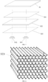
- the sound-emitting substrate includes: a first skin 321, a middle layer 322 and a second skin 323.
- the first skin 321 is attached to a first side of the middle layer 322 and the second skin 323 is attached to a second side of the middle layer 322 opposite the first side, surface areas of the first skin 321, the middle layer 322 and the second skin 323 are the same; in some other embodiments, the first skin 321 and the second skin 323 may cover at least part of the middle layer 322.
- FIG. 8 is a schematic structural diagram of a middle layer of a sound-emitting substrate according to an embodiment of the present disclosure.
- the middle layer of the sound-emitting substrate 32 according to the embodiment of the present disclosure is formed by connecting a plurality of honeycomb cores 3221 presented in a hexagonal shape, except for the honeycomb cores located around the structure, sides corresponding to six sides of each honeycomb core 3221 are respectively connected to corresponding sides of the other six honeycomb cores.
- FIG. 9 is a schematic diagram of an attaching structure of a middle layer, a first skin and a second skin of a sound-emitting substrate according to an embodiment of the present disclosure. As shown in FIG.
- a section of the honeycomb core 3221 included in the middle layer 322 is perpendicular to the first skin 321 and the second skin 323.
- the middle layer which includes honeycomb cores is arranged with two parallel sides of a hexagonal honeycomb core wall to parallel to y direction and there is no parallel side of the honeycomb core wall in x direction, so that the sound-emitting substrate has different transmission performance in the x direction and the y direction.
- FIG. 10 is a schematic diagram of a sectional view of a middle layer of a sound-emitting substrate according to an embodiment of the present disclosure. As shown in FIG.
- the stretch ratio of the hexagonal section of the honeycomb core in the x-y directions is d/L.
- a first direction is set as the y direction in the figure and a second direction is set as the x direction in the figure.
- d is a unit length of each honeycomb core in the x direction when multiple hexagonal honeycomb cores are arranged in order
- the unit length d refers to a minimum length unit in the x direction after multiple hexagonal honeycomb cores are arranged in order. That is, multiple hexagonal honeycomb cores are arranged in a pattern consistent with unit length d along the x direction.
- the unit length d is the shortest distance between side 3 and side 6 of the hexagon which perpendicular to the x-axis.
- the unit length L is a unit length of each honeycomb core in the y direction when multiple hexagonal honeycomb cores are arranged in order
- the unit length L refers to a minimum length unit in the y direction when multiple hexagonal honeycomb cores are arranged in order. That is, multiple hexagonal honeycomb cores are arranged in a pattern consistent with unit length L in the y direction.
- the unit length L is a sum of the distances of sides 1, 6, 5, and 7 of the hexagonal in the y direction.
- the stretch ratio in the x-y directions is 0.58: 1.
- all honeycomb cores in the middle layer of the sound-emitting substrate may be stretched in the x direction of the hexagonal section at a preset stretch ratio, where the preset stretch ratio is less than a preset threshold of 0.58: 1.
- the stretch ratio d/L being smaller means that the distribution of the hexagonal interface of the honeycomb cores shown in FIG. 10 along parallel walls in the y direction is denser and the rigidity is stronger, so it is easy to transmit the waves through vibrations; it also means that an angle of the hexagonal honeycomb core wall in the x direction is larger and the rigidity is weaker, so it is easy to absorb the transmission of the vibrations of the waves.
- the stretch ratio of the honeycomb core in the middle layer the transmission performances of the sound-emitting substrate in the x direction and the y direction are different, the amplitude attenuation pattern in the x direction and the y direction are different when the sound-emitting substrate transmits the wave.
- the stretch ratio in the x-y directions is less than 0.58: 1
- the transmission performance of the sound-emitting substrate with respect to the wave in the x direction is weaker than that in the y direction, causing an amplitude attenuation degree of the wave in the x direction is larger than that of the wave in the y direction when the sound-emitting substrate provided with the middle layer as shown in FIG. 10 transmits the wave.
- first skin and the second skin are attached to both sides of the middle layer, in order to match the transmission performance of the middle layer in x-y directions, in the middle layer according to the embodiment of the present disclosure, fibers of the first skin and the second skin are also made adaptions.
- FIG. 11 is a schematic structural diagram of a first skin and a second skin of a sound-emitting substrate according to an embodiment of the present disclosure.
- the skin may be the first skin or the second skin in the foregoing embodiment.
- the skin structure shown in FIG. 11 is a mixed fiber structure in x-y directions, in which a density of fibers parallel to the y direction and perpendicular to the x direction is greater than a density of fibers parallel to the x direction and perpendicular to the y direction.
- first skin and a second skin in another structure of a first skin and a second skin according to an embodiment of the present disclosure, fibers parallel to the x direction and perpendicular to the y direction may not be provided. That is, the first skin and the second skin are unidirectional fiber structures, and the direction of all the fibers is parallel to the y direction and perpendicular to the x direction.
- the structure of the first skin and the second skin as shown in FIG. 11 can cooperate with the middle layer, so that when the sound-emitting substrate transmits the wave, the amplitude attenuation pattern in the x direction and the y direction are different.
- the fibers of the first skin and the second skin have a denser parallel fiber distribution in the y direction, and the rigidity is stronger, so it is easier to transmit the wave through vibrations; and the fibers of the first skin and the second skin has relatively sparser parallel fiber distribution in the x direction, and the rigidity is weaker, so it is not easy to transmit the wave through vibrations. Therefore, for a sound-emitting substrate provided with the middle layer as shown in FIG. 10 and the first skin and the second skin as shown in FIG. 11 , when the sound-emitting substrate transmits the wave, an amplitude attenuation degree of the wave in the x direction is larger than that of the wave in the y direction.
- the material of the honeycomb core may be paper, aramid, metal, or other composite materials.
- the materials of the first skin and the second skin include but not limited to glass fiber, carbon fiber, glass-carbon mixed fiber, plastic, lightweight aluminum, and so on.
- the thicknesses of the first skin and the second skin may be the same or different, and the thicknesses of the first skin and the second skin may range from 0.1 mm to 0.5 mm; or the thicknesses of the first skin and the second skin may range from 0.18 mm to 0.36 mm.
- the x-y directions perpendicular to each other is used as an example of the first and second directions for description.
- the y direction may be the up and down directions of the electronic device
- the x direction may be the left and right directions of the electronic device.
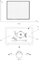
- FIG. 12 is a schematic structural diagram of an electronic device with a display apparatus according to an embodiment of the present disclosure.
- the electronic device shown in FIG. 12 includes the display apparatus described in any of FIGS. 6-11 .
- a user can view the display content through the display structure 31 of the display apparatus. Meanwhile, the sound played by the electronic device needs to output from the left and right channels. Therefore, with the user's viewing direction as the center, the first electromagnetic actuator 331 is arranged on the left side of the display apparatus at the same height, and the second electromagnetic actuator 332 is arranged on the right side of the display apparatus at the same height.
- the x direction is the left and right sides of the user's viewing direction in FIG. 12
- the y direction is the up and down sides of the user's viewing direction in FIG. 12 .
- FIG. 13 is a schematic diagram of an amplitude attenuation pattern when a display apparatus transmitting a wave according to an embodiment of the present disclosure.
- FIG. 13 shows an amplitude attenuation degrees of the sound-emitting substrate 32 in different directions driven by the first electromagnetic actuator 331 in the screen shown in FIG. 12 .
- the amplitude of point P at a certain moment is set as 100% ⁇ D, when the wave emits around in a 360-degree direction range taking the point P as the center, the amplitude gradually attenuates from 100% ⁇ D to 90% ⁇ D, 80% ⁇ D...
- the amplitude attenuation value and attenuation speed of the amplitude at point P in the x direction are greater than those of the amplitude at point P in the y direction.
- the waves driven by the electromagnetic actuator 331 and the electromagnetic actuator 332 and emitted through the sound-emitting substrate have a small attenuation when transmitting in the up and down or vertical direction, and a large attenuation when transmitting in the left and right or horizontal direction. Therefore, because the wave which is obtained from the electromagnetic actuator 331 on the left actuating the sound-emitting substrate 32, attenuates quickly when it transmits to the right, the strength of the wave on the left is greater than the strength of the wave on the right. Meanwhile, the user can hear that the sound from the left side of the screen is greater than the sound from the right side of the screen, so that the sound of the left channel corresponding to the electromagnetic actuator 331 can be distinguished.
- the wave which is obtained from the electromagnetic actuator 332 on the right actuating the sound-emitting substrate 32 attenuates quickly when it transmits to the left, the strength of the wave on the right is greater than the strength of the wave on the left. Meanwhile, the user can hear that the sound from the right side of the screen is greater than the sound from the left side of the screen, so that the sound of the right channel corresponding to the electromagnetic actuator 332 can be distinguished.
- the sound-emitting substrate can have different amplitude attenuations in different directions when transmitting the wave generated from the electromagnetic actuator, thereby improving the discrimination of the sound channels in the display apparatus when the display apparatus generates sounds with the electromagnetic actuators corresponding to different sound channels, furthermore improving the user experience of the electronic device with the display apparatus.
- an isolation area may be arranged in the middle layer of the sound-emitting substrate, so that the first electromagnetic actuator and the second electromagnetic actuator respectively generate and transmit the wave by exciting areas on both sides of the isolation area.
- FIG. 14 is a schematic structural diagram of a middle layer of a sound-emitting substrate according to an embodiment of the present disclosure.
- the middle layer of the sound-emitting substrate 32 provided in the embodiment shown in FIG. 14 includes: a first area corresponding to the electromagnetic actuator 331 on the left side, an isolation area, and a second area corresponding to the electromagnetic actuator 332 on the right side.
- the first area, the second area and the isolation area consist of honeycomb cores in a hexagonal shape.
- stretch ratios of honeycomb cores in the first area and the second area are greater than a stretch ratio of honeycomb cores in the isolation area.
- the strength of the wave in the first area on the left is significantly greater than the strength of the wave in the second area on the right, which further allows the user to clearly hear the sound from the left side of the screen, but hardly hear the sound from the right side of the screen. That is, the sound of the left channel corresponding to the electromagnetic actuator 331 can be distinguished more clearly.
- the amplitude of the wave when the wave passes through the isolation area will be attenuated significantly.
- the strength of the wave in the second area on the right is significantly greater than the strength of the wave in the first area on the left, which further allows the user to clearly hear the sound from the right side of the screen, but hardly hear the sound from the left side of the screen. That is, the sound of the right channel corresponding to the electromagnetic actuator 332 can be distinguished more clearly.
- FIG. 15 is a schematic structural diagram of a middle layer of a sound-emitting substrate according to another embodiment of the present disclosure.
- the structure of the sound-emitting substrate 32 in the embodiment shown in FIG. 15 is similar to that of the sound-emitting substrate 32 shown in FIG. 14 , except that the honeycomb cores in the isolation area is filled with foam damping material.
- the foam damping material in the isolation area is configured to increase the amplitude attenuation of the sound-emitting substrate when the sound-emitting substrate transmits the wave in the x direction.
- an embodiment of the present disclosure further provides a stabilizer for supporting the electromagnetic actuator to prevent the electromagnetic actuator from deviating from an optimum working area and reduce twisting motion of the electromagnetic actuator in different directions due to vibration, thereby reducing a distortion of the sound generated by the display apparatus under the control of the electromagnetic actuator.
- FIG. 16 is a schematic diagram of a sectional view after a stabilizer is installed according to an embodiment of the present disclosure
- FIG. 17 is a schematic diagram of an installation structure of a stabilizer and an electromagnetic actuator according to an embodiment of the present disclosure.
- the stabilizer 7 includes: a bracket 72 and a plurality of flexible support feet 71 extending away from the bracket 72.
- Each foot 71 extends in a direction away from the bracket 72, and the plurality of feet 71 are distributed on a peripheral of a first circle (not shown in FIGS. 17 and 18 ).
- a center of the first circle is located on an axis of the bracket 72 (not shown in FIGS. 17 and 18 ), and the first circle may be any circle whose center is located on the axis of the bracket 72.
- the bracket 72 has a first fixed position (not shown in FIGS.
- the axis of the first fixed position may be collinear with the axis of the bracket 72, and a vibration output of the electromagnetic actuator 331 passes through the first fixed position of the bracket 72 and abuts against the sound-emitting substrate 32.
- the stabilizer may be referred to as a "spider structure" due to its outwardly extending feet.
- the bracket 72 of the stabilizer has a chamber whose shape matches that of the electromagnetic actuator 331 and is configured to receive and fix the electromagnetic actuator. Then, when the electromagnetic actuator 331 is circular, the shape of the cavity is circular; when the electromagnetic actuator 331 is elliptical, the shape of the cavity is elliptical.
- the stabilizer 7 further includes at least one damping block 8, a first damping block among the at least one damping block 8 is disposed at one end of a first foot of the plurality of feet 71.
- the number of the at least one damping block 8 is less than or equal to the number of the feet 71, and the damping block 8 is fixedly connected to the sound-emitting substrate 32.
- the plurality of feet 71 may be configured to extend along a peripheral of the stabilizer 7 (that is, the plurality of feet 71 extend away from a center of the stabilizer 7 and around the outer edge of the stabilizer), or the plurality of feet 71 may be configured to extend along a direction away from an axis of the stabilizer 7 (that is, the plurality of feet 71 can be radially extended).
- the four feet 71 of the stabilizer 7 as shown in FIG. 17 are respectively fixed to the second skin 323 of the sound-emitting substrate 32 through a damping block 8.
- the stabilizer can form a mechanical low-pass filter position stabilizer for the vibration from the flat-panel devices. That is, each support point of the flexible support feet of the position stabilizer receives different random vibrations of the wave, which is being filtered by a mechanical low-pass filter to maintain a stable state, thereby keeping the electromagnetic actuator 331 in the bracket 72 stable.
- the stabilizer 7 can make the electromagnetic actuator 331 and the sound-emitting substrate 32 relatively stable and ensure that the electromagnetic actuator 331 does not have axial rotation. Furthermore, the structure of the stabilizer 7 makes the stabilizer 7 serve as a mechanical low-pass filter (similar to a damper), so that the vibration is filtered after being transmitted to the feet 72 of the stabilizer 7, and does not affect the vibration of the electromagnetic actuator 331 itself.
- the electromagnetic actuator 331 includes a drive coil and a magnetic pole component, where the magnetic pole component may generate a magnetic field, and the drive coil may generate a large electric power at a center of the magnetic field to actuate the drive coil.
- the stabilizer 7 may prevent the drive coil of the electromagnetic actuator from deviating from the center of the magnetic field due to the vibration of the sound-emitting substrate, thereby ensuring that the electromagnetic actuator is in an optimum working state.
- the stabilizer 7 may ensure that the electromagnetic actuator does not have axial displacement, which will greatly reduce the distortion of the sound generated from the sound-emitting substrate.
- FIG. 18 is a schematic diagram of a stabilizer with other structures according to an embodiment of the present disclosure.
- FIG. 18 shows several other structures of the stabilizer, in which the stabilizer may have 3 or 4 feet, and the feet can extend around or radially extend away from the bracket.
- the implementation and principles are similar to the stabilizer shown in FIG. 17 , which will omit here.
- a display apparatus further includes a support mechanism to support the display apparatus.
- the support mechanism may be a frame for the display apparatus.
- FIG. 19 is a schematic diagram of a sectional view of a support mechanism according to an embodiment of the present disclosure. As shown in FIG. 19 , edges of the sound-emitting substrate 32 and the display structure 31 are supported by the support mechanism 5 after being wrapped by a suspension structure 6.
- the suspension structure 6 is configured to receive the sound-emitting substrate 32 and the display structure 31, and the suspension structure 6 may be a foam adhesive tape.
- the support mechanism 5 is arranged on a side of the sound-emitting substrate 32 close to the electromagnetic actuator, and further includes: a first support structure 501 and a second support structure 502 to jointly support and fix the electromagnetic actuator on a side of the sound-emitting substrate 32.
- FIG. 20 is a schematic diagram of a sectional view of a support mechanism according to another embodiment of the present disclosure
- FIG. 21 is a schematic structural diagram of a support mechanism according to another embodiment of the present disclosure.
- a support mechanism according to an embodiment of the present disclosure includes: a back cover 503, a cushion member 504 and a seal buffer material 505.
- the cushion member 504 is a sound damping isolation ring, which can be made from EVA foam material.
- FIG. 22 is a schematic structural diagram of an implementation of a display apparatus according to an embodiment of the present disclosure
- FIG. 23 is a schematic diagram of an exploded view of an implementation of a display apparatus according to an embodiment of the present disclosure.
- FIG. 23 shows an arrangement of an electromagnetic actuator, a frame structure, and a cushion member in the electronic device with a display apparatus. In the example shown in FIG.
- the display apparatus is provided with multiple electromagnetic actuators a, b, c, d, e and f with different excitation frequencies according to a play performance requirement that the electronic device needs to meet, so that the waves with different resonance frequencies are generated by different electromagnetic actuators through exciting the sound-emitting substrate, thereby broadening the frequency response of the display apparatus.
- the sound-emitting substrate of the display apparatus has different transmission performances in the x direction and y direction as shown in the figure, and thus when the sound-emitting substrate transmits the wave, the amplitude attenuation pattern in the x direction and y direction are different.
- the left channel of the display apparatus in the figure corresponds to the electromagnetic actuators a, c and d in a negative x direction, that is, the electromagnetic actuators a, c and d can be configured to excite the display apparatus to generate waves corresponding to the left channel signal;
- the right channel of the display apparatus in the figure corresponds to the electromagnetic actuators b, e and f in a positive x direction, that is, the electromagnetic actuators b, e and f can be configured to excite the display apparatus to generate a wave corresponding to the right channel signal.
- Electromagnetic actuators with different performances are arranged in an oblique line, and the electromagnetic actuators at an upper end of the y direction is closer to the edge of the display apparatus.
- the electromagnetic actuators corresponding to the left channel and the electromagnetic actuators corresponding to the right channel are generally arranged in a "v" shape on the display apparatus.
- the structure of the display apparatus in FIG. 22 can refer to FIG. 23 , where the display structure 31 and the sound-emitting substrate 32 of the display apparatus are attached to each other, and edges of the two are wrapped by the suspension structure (foam double-sided adhesive tape) 6 and then fixed by the support mechanism 5. Meanwhile, the electromagnetic actuator a and the electromagnetic actuator b are fixed by a first support structure 501, and two ends of the first support structure 501 are arranged between longer sides of the support mechanism 5. A connection manner between the first support structure 501 and the electromagnetic actuators can refer to FIG. 19 .
- each electromagnetic actuator as shown in the figure is mounted on the sound-emitting substrate 32 through the stabilizer 7.
- FIGS. 22 and 23 is only exemplary illustration of the display apparatus in an implementation, and installation manner and position setting manner of different numbers of electromagnetic actuators are all within the protection scope of the present disclosure.
- FIG. 24 is a schematic structural diagram of implementations of display apparatus according to another embodiment of the present disclosure, which shows arrangement and strength direction of the electromagnetic actuator, the frame structure and the cushion member in the electronic device with the display apparatus.
- the left channel and the right channel each correspond to two electromagnetic actuators, and the two electromagnetic actuators are arranged on the same support structure; in a schematic diagram B, the left channel and the right channel each correspond to two electromagnetic actuators, and the two electromagnetic actuators are arranged in the same back cover and cushion member; in a schematic diagram C, the left channel and the right channel each correspond to three electromagnetic actuators, and only one of the three electromagnetic actuators is arranged on the support structure; in a schematic diagram D, the left channel and the right channel each correspond to three electromagnetic actuators, and two of the three electromagnetic actuators are arranged in the same back cover and cushion member, and the other electromagnetic actuator is arranged in a back cover and cushion member.
- FIG. 25 is a schematic structural diagram of an electronic device according to an embodiment of the present disclosure.
- the electronic device 20 according to the embodiment of the present disclosure includes: the display apparatus 2001 as described in any of the embodiments of FIGS. 6-24 .
- the electronic device includes but not limited to the following devices: mobile phone, tablet computer, desktop computer, television, and other electrical appliances with display screens, such as washing machine, refrigerator, and so on.
Abstract
Description
- This application claims priority to
Chinese Patent Application No. 201910523147.1, filed on June 17, 2019 - Embodiments of the present disclosure relate to electronic technology, and in particular, to a display apparatus and an electromagnetic actuator.
- With the continuous development of electronic technology and the continuous growth in customer demands, electronic device is developing towards large size, thin thickness and light weight. An electronic device, such as mobile phone, tablet computer, television, or the like, needs to equip with loudspeakers and other sound-emitting apparatus inside, meanwhile ensuring the device keep light and thin. Due to the limitation of the internal space of the electronic device, an installation space left for the loudspeakers is small, so that the loudspeakers installed in the electronic device usually only meets the ordinary play function, and cannot achieve more sound effects such as subwoofer and so on, in other words, resulting in poor play performance.
- Embodiments of the present disclosure provide a display apparatus and an electromagnetic actuator, which allows for better discrimination of the sound channels in the display apparatus when the display apparatus generate sounds with the electromagnetic actuators of different sound channels, thereby improving the user experience of an electronic device with the display apparatus and the electromagnetic actuator.
- An embodiment of the present disclosure provides a display apparatus, including:
- a display structure, a sound-emitting substrate, at least one electromagnetic actuator and a stabilizer;
- where one side of the sound-emitting substrate is attached to the display structure, and the at least one electromagnetic actuator is fixedly attached to the other side of the sound-emitting substrate through the stabilizer; the stabilizer includes: a bracket and a plurality of flexible support feet extending away from the bracket, where the bracket is configured to receive a first electromagnetic actuator among the at least one electromagnetic actuator, and the plurality of flexible support feet are configured to keep the first electromagnetic actuator stable.
- Secondly, an embodiment of the present disclosure provides an electromagnetic actuator including a stabilizer, where the stabilizer includes a bracket and a plurality of flexible support feet extending away from the bracket, where the bracket is configured to receive the electromagnetic actuator, and the plurality of flexible support feet are configured to keep the electromagnetic actuator stable.
- To describe the technical solutions in embodiments of the present disclosure or in the related art more clearly, the following briefly introduces the accompanying figures for describing the embodiments or the related art. Apparently, the accompanying figures in the following description illustrate merely some embodiments of the present disclosure, and persons of ordinary skill in the art may still obtain other figures from these accompanying figures without creative effort.
-
FIG. 1 is a schematic structural diagram for illustrating an electronic device with loudspeakers; -
FIG. 2 is a schematic structural diagram for illustrating another electronic device with loudspeakers; -
FIG. 3 is a schematic diagram of a sectional view of a display apparatus; -
FIG. 4 is a schematic diagram of an exploded structure of a display apparatus; -
FIG. 5 is a schematic diagram of an amplitude distribution of a wave generated by a display apparatus with an electromagnetic actuator; -
FIG. 6 is a schematic diagram of a sectional view of a display apparatus according to an embodiment of the present disclosure; -
FIG. 7 is a schematic diagram of an exploded view of a display apparatus according to an embodiment of the present disclosure; -
FIG. 8 is a schematic structural diagram of a middle layer of a sound-emitting substrate according to an embodiment of the present disclosure; -
FIG. 9 is a schematic diagram for illustrating an attaching structure for a middle layer, a first skin and a second skin of a sound-emitting substrate according to an embodiment of the present disclosure; -
FIG. 10 is a schematic diagram of a sectional view of a middle layer of a sound-emitting substrate according to an embodiment of the present disclosure; -
FIG. 11 is a schematic structural diagram of a first skin and a second skin of a sound-emitting substrate according to an embodiment of the present disclosure; -
FIG. 12 is a schematic structural diagram of an electronic device with a display apparatus according to an embodiment of the present disclosure; -
FIG. 13 is a schematic diagram of an amplitude attenuation pattern when a display apparatus transmitting a wave according to an embodiment of the present disclosure; -
FIG. 14 is a schematic structural diagram of a middle layer of a sound-emitting substrate according to an embodiment of the present disclosure; -
FIG. 15 is a schematic structural diagram of a middle layer of a sound-emitting substrate according to another embodiment of the present disclosure; -
FIG. 16 is a schematic diagram of a sectional view after a stabilizer is installed according to an embodiment of the present disclosure; -
FIG. 17 is a schematic diagram of an installation structure of a stabilizer and an electromagnetic actuator according to an embodiment of the present disclosure; -
FIG. 18 is a schematic diagram of a stabilizer with other structures according to an embodiment of the present disclosure; -
FIG. 19 is a schematic diagram of a sectional view of a support mechanism according to an embodiment of the present disclosure; -
FIG. 20 is a schematic diagram of a sectional view of a support mechanism according to another embodiment of the present disclosure; -
FIG. 21 is a schematic structural diagram of a support mechanism according to another embodiment of the present disclosure; -
FIG. 22 is a schematic structural diagram of an implementation of a display apparatus according to an embodiment of the present disclosure; -
FIG. 23 is a schematic diagram of an exploded view of an implementation of a display apparatus according to an embodiment of the present disclosure; -
FIG. 24 is a schematic structural diagram of implementations of display apparatus according to another embodiment of the present disclosure; and -
FIG. 25 is a schematic structural diagram of an electronic device according to an embodiment of the present disclosure. - To make the present disclosure and the scope of the present disclosure convenient for persons of ordinary skill in the art to understand, the following clearly and comprehensively describes exemplary embodiments. In order to fully understand the embodiments of the present disclosure, many specific details are described, such as examples of specific components, specific devices and specific methods. Apparently, persons of ordinary skill in the art understand that the discussed exemplary embodiments can be implemented in many different forms without relying on specific details, and that should not be construed as limiting the scope of the present disclosure. In some exemplary embodiments, well-known processes, well-known device structures, and well-known technologies are not described in detail.
- The terms herein are for the purpose of describing particular embodiments only, and are not intended to limit the present application. The singular forms "a" and "the" used herein are also intended to include the plurality forms unless indicated otherwise. The terms "including", "comprising" and "having" or any other variations thereof are intended to cover non-exclusive inclusions. For example, a process, method, system, product, or device that includes a series of steps or units is not limited to the listed steps or units, but optionally includes steps or units not listed, or optionally includes other steps or units which are inherent to these processes, methods, products, or device. Unless an order of execution is specified explicitly, the method steps, processes, and operations described herein should not be interpreted as having to be performed in the particular order discussed or illustrated. It should also be understood that additional steps or alternative steps may be employed.
- Although the terms first, second, third, or the like may be used herein to describe various elements, components, areas, layers and/or sections, these elements, components, areas, layers and/or sections should not be limited by these terms. These terms can only be used to distinguish one element, component, area, layer or section from another element, component, area, layer or section. Unless the context clearly dictates, terms such as "first", "second", and other numbers used herein do not imply a sequence or order. Therefore, without departing from the exemplary embodiments, the first element, first component, first area, first layer or first section discussed below may be referred to as the second element, second component, second area, second layer or second section.
- For convenience, spatially relative terms may be used herein, such as "inner", "outer", "below", "beneath", "lower", "above", "upper", etc. It is used to describe the relationship between an element or feature and another element or feature shown in the figure. In addition to the orientation depicted in the figure, spatial relative terms may also be intended to cover different orientations of the device in use or operation. For example, if the apparatus in the figures is turned over, elements described as being "below" or "beneath" other elements or features would then be redirected as being "above" the other elements or features. Thus, the exemplary term "below" can include both relative orientations of up and down. The device may be oriented in other ways (rotate 90 degrees or other directions), thereby explaining the relative spatial terms used herein.
- In the related art, an electronic device may use "sound-emitting technology for flat-panel devices", that is, an electromagnetic actuator is placed behind a display screen, which cause the display screen to make sound using a wave generated based on modal resonance driven by the electromagnetic actuator. In other words, the display screen in the electronic device can be used for display and furthermore it can replace a loudspeaker to perform sound-emitting. Therefore, there is no need to leave an installation position for the loudspeaker in the electronic device, making the design of the electronic device lighter and thinner.
- However, with the "sound-emitting technology for flat-panel devices", even if the display screen generates sound driven by multiple electromagnetic actuators of different sound channels, users cannot clearly distinguish the sound channel of the display screen, resulting in that the discrimination of different sound channels is poor when the display screen generate sound, which in turn affects user experience of the electronic device.
-
FIG. 1 is a schematic structural diagram of an electronic device with loudspeakers, a television is taken as an example of the electronic device. As shown inFIG. 1 , atelevision 11 includes adisplay screen 12 andloudspeakers 13, where theloudspeakers 13 are arranged behind thedisplay screen 12 inside thetelevision 11. Theloudspeakers 13 are generally set on left and right sides of a direction in which the user views thedisplay screen 12, and provide sounds from left and right channels. - Although with the continuous development of electronic technology, more and more key components in electronic devices such as display screens, basic frames, or the like, can be made with a thinner thickness, which can reduce the overall thickness of the electronic devices, but with the demands for the electronic devices gradually towards the direction of thinness and lightness, in the
display apparatus 11 shown inFIG. 1 , in addition of providing some apparatus for display, the space reserved for theloudspeakers 13 is becoming smaller and smaller. In order to make a television thinner and lighter, television manufacturers can only reduce the functions such as subwoofer of theloudspeakers 13 to reduce the space occupied by theloudspeakers 13 in thetelevision 11, resulting in that theloudspeakers 13 installed in thetelevision 11 can only meet the ordinary play function and cannot achieve more sound effects, which reduces the play performance of theloudspeakers 13. - In order to have better audio and video effects, an electronic device such as a laser projection television is usually provided with a separate projection screen and provided with a separate sound box as loudspeaker.
FIG. 2 is a schematic structural diagram of another electronic device with loudspeakers, the electronic device takes a laser projection television as an example. As shown inFIG. 2 , alaser projection television 21 not only can project a laser beam onto a display screen 22 for the user to view a video screen, but also can provide a sound signal to anexternal loudspeakers 23 connected thereto to make theloudspeakers 23 play audio. As shown inFIG. 2 , since thespeaker 23 needs to be set independently, thespeaker 23 can achieve better sound effects by having a large volume, and accordingly, thespeaker 23 of the electronic device needs to occupy more external space. - In the electronic devices shown in
FIGS. 1 and 2 , in addition to the location limitations of the loudspeakers, the sound played by both the loudspeakers installed in the electronic device and the external loudspeakers comes from outside of the display screen, leading to a lack of good audio-visual play effect. - Therefore, in related art, a "Sound on Display" is applied to the electronic devices. For example, referring to
FIGS. 3 and 4, FIG. 3 is a schematic diagram of a sectional view of a display apparatus; andFIG. 4 is a schematic diagram of an exploded view of a display apparatus. The display apparatus includes: anoptical film 31, a sound-emittingsubstrate 32 and anelectromagnetic actuator 33. Theoptical film 31 is configured to receive and display video or image content; the sound-emittingsubstrate 32 emits sound using a wave generated based on modal resonance driven by theelectromagnetic actuator 33. That is, the display apparatus in the electronic device can be used for both display and furthermore emit sound replacing the function of a loudspeaker. Thus, there is no need to leave an installation position for the loudspeaker in the electronic device, and the user does not need to externally connect a loudspeaker, making the design of the electronic device lighter and thinner. Meanwhile, since an area of the sound-emittingsubstrate 32 can be at most set to be equal to an area of theoptical film 31, and the larger the area of the sound-emitting substrate, the better the sound effects such as subwoofer and so on, which make the display apparatus have a better play performance. - However, in the display apparatus shown in
FIGS. 3 and 4 , since the sound-emittingsubstrate 32 is set integrally, no matter how manyelectromagnetic actuators 33 are provided, eachelectromagnetic actuator 33 works on the same sound-emittingsubstrate 32 to make the sound-emittingsubstrate 32 emit sound using the wave generated based on modal resonance.FIG. 5 is a schematic diagram of an amplitude distribution of a wave generated from a display apparatus driven by an electromagnetic actuator. Referring toFIG. 5 , the schematic diagram of the amplitude of the wave in the sound-emittingsubstrate 32 will be described as an example. The sound-emittingsubstrate 32 generates a wave driven by theelectromagnetic actuators 33. The wave transmits around a center where theelectromagnetic actuators 33 and the sound-emittingsubstrate 32 are bonded, and covers the entire sound-emittingsubstrate 32. The darker the color of the sound-emittingsubstrate 32 in this figure, the greater the amplitude of the wave at the position toward the upward side of the display apparatus; the lighter the color in this figure, the lower the amplitude of the wave at the position toward the downward side of the display apparatus. - In
FIG. 5 , a frequency of wave A is 200 Hz, a frequency of wave B is 1000 Hz, and a frequency of wave is 10000 Hz. It can be seen that no matter how the frequency of the wave changes, an amplitude of the wave in all directions are not attenuated much when it transmits in the sound-emitting substrate. Even at the rightmost position away from theelectromagnetic actuator 33 in this figure, the amplitude of the wave and the amplitude near theelectromagnetic actuator 33 are basically the same. That is, the amplitude distribution of the wave, which generated from the sound-emittingsubstrate 32 under the control of theelectromagnetic actuator 33, at all positions is relatively uniform when the wave transmits in the sound-emittingsubstrate 32, causing the sound-emittingsubstrate 32 as a whole emit a sound with a similar strength. When the user hears the sound emitted from the display apparatus, the intuitive feeling is that all positions of the entire screen are emitting similar sounds, and it seems impossible to distinguish sound channels corresponding to different electromagnetic actuators, resulting in poor discrimination of different sound channels in the sound-emitting process of the display apparatus, which in turn affects the user experience of the electronic device. - Therefore, the present disclosure provides a display apparatus and an electromagnetic actuator. When the wave generated from the electromagnetic actuator transmitting in the sound-emitting substrate, the amplitude attenuations in different directions are different, thereby allowing for better discrimination of the sound channels in the display apparatus when the display apparatus generate sounds with the electromagnetic actuator of different sound channels, furthermore improving the user experience of the electronic device with the display apparatus and the electromagnetic actuator.
- The technical solutions of the present disclosure will be discussed in detail hereinafter with specific embodiments. The following specific embodiments can be combined with each other, and the same or similar concepts or processes are omitted in some embodiments.
-
FIG. 6 is a schematic diagram of a sectional view of a display apparatus according to an embodiment of the present disclosure; andFIG. 7 is a schematic diagram of an exploded view of a display apparatus according to an embodiment of the present disclosure. In the embodiment shown inFIGS. 6 and7 , a laser TV is used as an example of the display apparatus for description, not for limitation. - The display apparatus according to the embodiment of the present disclosure includes: a
display structure 31, a sound-emittingsubstrate 32 and at least oneelectromagnetic actuator 33. Thedisplay structure 31 is attached to one side of the sound-emittingsubstrate 32, and the at least oneelectromagnetic actuator 33 is attached to the other side of the sound-emittingsubstrate 32. A surface area of the sound-emittingsubstrate 32 is equal to or smaller than a surface area of thedisplay structure 31. - In a first aspect, the
display structure 31 of the display apparatus is configured to realize a display function of the display apparatus, and configured to receive and display an optical signal. Thedisplay structure 31 according to the embodiment of the present disclosure includes but not limited to: a liquid crystal display (LCD), an organic light-emitting diode (OLED), a laser projection hard screen, an image display membrane or a touch sensitive membrane, the image display membrane includes but not limited to, a membrane with optical microstructures such as Fresnel film, bar grid film, or microlens array and so on. In the embodiment of the present disclosure, a rectangular structure is used as an example of the display structure for description. In other embodiments, other structures may be used. For example, the display structure may also be an arcuate structure. - In a second aspect, the
display structure 31, the sound-emittingsubstrate 32 and the at least oneelectromagnetic actuator 33 of the display apparatus work together to realize the sound-emitting function of the display apparatus. In the example shown inFIGS. 6 and7 , the at least oneelectromagnetic actuator 33 includes two electromagnetic actuators, the two electromagnetic actuators are: a firstelectromagnetic actuator 331 and a secondelectromagnetic actuator 332. In other embodiments, more electromagnetic actuators may be included, and the implementation principles are similar, which will omit here. Taking theelectromagnetic actuator 331 as an example, theelectromagnetic actuator 331 is configured to receive an electrical signal corresponding to the sound to be played, and convert the electrical signal into mechanical vibrations, and then apply the mechanical vibrations to the sound-emittingsubstrate 32. The sound-emittingsubstrate 32 generate waves under the action of the mechanical vibration of theelectromagnetic actuator 331 according to by modal resonance, and the waves transmit in a 360-degree direction around a bonding position of theelectromagnetic actuator 331 and the sound-emittingsubstrate 32. The sound-emittingsubstrate 32 and thedisplay structure 31 to which the sound-emittingsubstrate 32 is attached, under the control of the waves transmitting in the sound-emittingsubstrate 32, perform reciprocating vibrations in up and down directions of a sectional view of the display apparatus shown inFIG. 6 , so as to generate sound. - With respect to the sound-emitting
substrate 32 according to the embodiment of the present disclosure, when transmitting the waves in a 360-degree direction range around the bonding position of theelectromagnetic actuator 331 and the sound-emittingsubstrate 32, an amplitude attenuation pattern caused by the sound-emittingsubstrate 32 with respect to the waves in a first direction is different from an amplitude attenuation pattern caused by the sound-emittingsubstrate 32 with respect to the waves in a second direction. The attenuation pattern refer to a change mode of amplitude attenuations. - In some embodiments, in order to achieve different amplitude attenuation pattern of the sound-emitting
substrate 32 in different directions when transmitting waves, in an embodiment of the present disclosure, the material of the sound-emittingsubstrate 32 may be configured to cause the performance of the sound-emitting substrate transmit the waves in the first direction is different from the performance of the sound-emitting substrate transmitting the waves in the second direction. That is, the sound-emittingsubstrate 32 according to the embodiment of the present disclosure has a specific orthonormal and/or zone-strength anisotropy mechanical structure and transmission performance. - In some embodiments, as shown in
FIGS. 6 and7 , the sound-emitting substrate according to the embodiment of the present disclosure includes: afirst skin 321, amiddle layer 322 and asecond skin 323. In some embodiments, thefirst skin 321 is attached to a first side of themiddle layer 322 and thesecond skin 323 is attached to a second side of themiddle layer 322 opposite the first side, surface areas of thefirst skin 321, themiddle layer 322 and thesecond skin 323 are the same; in some other embodiments, thefirst skin 321 and thesecond skin 323 may cover at least part of themiddle layer 322. - For example,
FIG. 8 is a schematic structural diagram of a middle layer of a sound-emitting substrate according to an embodiment of the present disclosure. As shown inFIG. 8 , the middle layer of the sound-emittingsubstrate 32 according to the embodiment of the present disclosure is formed by connecting a plurality ofhoneycomb cores 3221 presented in a hexagonal shape, except for the honeycomb cores located around the structure, sides corresponding to six sides of eachhoneycomb core 3221 are respectively connected to corresponding sides of the other six honeycomb cores. In addition,FIG. 9 is a schematic diagram of an attaching structure of a middle layer, a first skin and a second skin of a sound-emitting substrate according to an embodiment of the present disclosure. As shown inFIG. 9 , in the sound-emitting substrate, a section of thehoneycomb core 3221 included in themiddle layer 322 is perpendicular to thefirst skin 321 and thesecond skin 323. In some embodiments, the middle layer which includes honeycomb cores is arranged with two parallel sides of a hexagonal honeycomb core wall to parallel to y direction and there is no parallel side of the honeycomb core wall in x direction, so that the sound-emitting substrate has different transmission performance in the x direction and the y direction. By adjusting a stretch ratio of the section of thehoneycomb core 3221, the transmission performances in different directions are different.FIG. 10 is a schematic diagram of a sectional view of a middle layer of a sound-emitting substrate according to an embodiment of the present disclosure. As shown inFIG. 10 , the stretch ratio of the hexagonal section of the honeycomb core in the x-y directions is d/L. A first direction is set as the y direction in the figure and a second direction is set as the x direction in the figure. Then d is a unit length of each honeycomb core in the x direction when multiple hexagonal honeycomb cores are arranged in order, the unit length d refers to a minimum length unit in the x direction after multiple hexagonal honeycomb cores are arranged in order. That is, multiple hexagonal honeycomb cores are arranged in a pattern consistent with unit length d along the x direction. InFIG. 10 , the unit length d is the shortest distance between side ③ andside ⑥ of the hexagon which perpendicular to the x-axis. L is a unit length of each honeycomb core in the y direction when multiple hexagonal honeycomb cores are arranged in order, the unit length L refers to a minimum length unit in the y direction when multiple hexagonal honeycomb cores are arranged in order. That is, multiple hexagonal honeycomb cores are arranged in a pattern consistent with unit length L in the y direction. InFIG. 10 , the unit length L is a sum of the distances ofsides - For a standard hexagon, the stretch ratio in the x-y directions is 0.58: 1. In an embodiment of the present disclosure, in order to make the sound-emitting substrate has different transmission performances in different directions, all honeycomb cores in the middle layer of the sound-emitting substrate may be stretched in the x direction of the hexagonal section at a preset stretch ratio, where the preset stretch ratio is less than a preset threshold of 0.58: 1.
- The stretch ratio d/L being smaller means that the distribution of the hexagonal interface of the honeycomb cores shown in
FIG. 10 along parallel walls in the y direction is denser and the rigidity is stronger, so it is easy to transmit the waves through vibrations; it also means that an angle of the hexagonal honeycomb core wall in the x direction is larger and the rigidity is weaker, so it is easy to absorb the transmission of the vibrations of the waves. - Therefore, by setting the stretch ratio of the honeycomb core in the middle layer, the transmission performances of the sound-emitting substrate in the x direction and the y direction are different, the amplitude attenuation pattern in the x direction and the y direction are different when the sound-emitting substrate transmits the wave. In the embodiment shown in
FIG. 10 , when the stretch ratio in the x-y directions is less than 0.58: 1, the transmission performance of the sound-emitting substrate with respect to the wave in the x direction is weaker than that in the y direction, causing an amplitude attenuation degree of the wave in the x direction is larger than that of the wave in the y direction when the sound-emitting substrate provided with the middle layer as shown inFIG. 10 transmits the wave. - Since the first skin and the second skin are attached to both sides of the middle layer, in order to match the transmission performance of the middle layer in x-y directions, in the middle layer according to the embodiment of the present disclosure, fibers of the first skin and the second skin are also made adaptions.
- For example,
FIG. 11 is a schematic structural diagram of a first skin and a second skin of a sound-emitting substrate according to an embodiment of the present disclosure. As shown in the schematic diagram of the fiber structure on the surface of the skin inFIG. 11 , the skin may be the first skin or the second skin in the foregoing embodiment. The skin structure shown inFIG. 11 is a mixed fiber structure in x-y directions, in which a density of fibers parallel to the y direction and perpendicular to the x direction is greater than a density of fibers parallel to the x direction and perpendicular to the y direction. - Alternatively, in another structure of a first skin and a second skin according to an embodiment of the present disclosure, fibers parallel to the x direction and perpendicular to the y direction may not be provided. That is, the first skin and the second skin are unidirectional fiber structures, and the direction of all the fibers is parallel to the y direction and perpendicular to the x direction.
- Therefore, the structure of the first skin and the second skin as shown in
FIG. 11 can cooperate with the middle layer, so that when the sound-emitting substrate transmits the wave, the amplitude attenuation pattern in the x direction and the y direction are different. In the embodiment shown inFIG. 11 , the fibers of the first skin and the second skin have a denser parallel fiber distribution in the y direction, and the rigidity is stronger, so it is easier to transmit the wave through vibrations; and the fibers of the first skin and the second skin has relatively sparser parallel fiber distribution in the x direction, and the rigidity is weaker, so it is not easy to transmit the wave through vibrations. Therefore, for a sound-emitting substrate provided with the middle layer as shown inFIG. 10 and the first skin and the second skin as shown inFIG. 11 , when the sound-emitting substrate transmits the wave, an amplitude attenuation degree of the wave in the x direction is larger than that of the wave in the y direction. - In some embodiments, the material of the honeycomb core may be paper, aramid, metal, or other composite materials.
- In some embodiments, the materials of the first skin and the second skin include but not limited to glass fiber, carbon fiber, glass-carbon mixed fiber, plastic, lightweight aluminum, and so on.
- In some embodiments, the thicknesses of the first skin and the second skin may be the same or different, and the thicknesses of the first skin and the second skin may range from 0.1 mm to 0.5 mm; or the thicknesses of the first skin and the second skin may range from 0.18 mm to 0.36 mm.
- In the embodiments shown in
FIGS. 6-11 , the x-y directions perpendicular to each other is used as an example of the first and second directions for description. In application scenarios, due to the requirement for setting the left and right channels of the electronic device, for the x-y directions described in the present disclosure, in some embodiments, the y direction may be the up and down directions of the electronic device, and the x direction may be the left and right directions of the electronic device. -
FIG. 12 is a schematic structural diagram of an electronic device with a display apparatus according to an embodiment of the present disclosure. The electronic device shown inFIG. 12 includes the display apparatus described in any ofFIGS. 6-11 . A user can view the display content through thedisplay structure 31 of the display apparatus. Meanwhile, the sound played by the electronic device needs to output from the left and right channels. Therefore, with the user's viewing direction as the center, the firstelectromagnetic actuator 331 is arranged on the left side of the display apparatus at the same height, and the secondelectromagnetic actuator 332 is arranged on the right side of the display apparatus at the same height. - For the electronic device shown in
FIG. 12 , when using the display apparatus described in any ofFIGS. 6-11 , the x direction is the left and right sides of the user's viewing direction inFIG. 12 , and the y direction is the up and down sides of the user's viewing direction inFIG. 12 . -
FIG. 13 is a schematic diagram of an amplitude attenuation pattern when a display apparatus transmitting a wave according to an embodiment of the present disclosure.FIG. 13 shows an amplitude attenuation degrees of the sound-emittingsubstrate 32 in different directions driven by the firstelectromagnetic actuator 331 in the screen shown inFIG. 12 . In the x-y directions, the point P(0,0) where x=0 and y=0 in the figure is set as a position where the firstelectromagnetic actuator 331 attached to the sound-emittingsubstrate 32, then the wave emitted from the sound-emittingsubstrate 32 under the control of the firstelectromagnetic actuator 331 transmits around point P as the center, and the amplitude of the sound-emitting substrate at point P is the largest. The amplitude of point P at a certain moment is set as 100% × D, when the wave emits around in a 360-degree direction range taking the point P as the center, the amplitude gradually attenuates from 100% × D to 90% × D, 80% × D... Especially for the x direction and the y direction, when the surface wave emits in these two directions, because the stretch ratio of the honeycomb cores of the middle layer is less than the preset threshold and the density of the first skin and the second skin in the y direction is greater than the density in the x direction, the amplitude attenuation value and attenuation speed of the amplitude at point P in the x direction are greater than those of the amplitude at point P in the y direction. - For the electronic device shown in
FIG. 12 , the waves driven by theelectromagnetic actuator 331 and theelectromagnetic actuator 332 and emitted through the sound-emitting substrate have a small attenuation when transmitting in the up and down or vertical direction, and a large attenuation when transmitting in the left and right or horizontal direction. Therefore, because the wave which is obtained from theelectromagnetic actuator 331 on the left actuating the sound-emittingsubstrate 32, attenuates quickly when it transmits to the right, the strength of the wave on the left is greater than the strength of the wave on the right. Meanwhile, the user can hear that the sound from the left side of the screen is greater than the sound from the right side of the screen, so that the sound of the left channel corresponding to theelectromagnetic actuator 331 can be distinguished. Similarly, because the wave which is obtained from theelectromagnetic actuator 332 on the right actuating the sound-emittingsubstrate 32, attenuates quickly when it transmits to the left, the strength of the wave on the right is greater than the strength of the wave on the left. Meanwhile, the user can hear that the sound from the right side of the screen is greater than the sound from the left side of the screen, so that the sound of the right channel corresponding to theelectromagnetic actuator 332 can be distinguished. - Therefore, in the display apparatus according to the embodiments of the present disclosure, by setting the stretch ratio of honeycomb cores in the middle layer of the sound-emitting substrate and the direction of the fibers of the first skin and the second skin, the sound-emitting substrate can have different amplitude attenuations in different directions when transmitting the wave generated from the electromagnetic actuator, thereby improving the discrimination of the sound channels in the display apparatus when the display apparatus generates sounds with the electromagnetic actuators corresponding to different sound channels, furthermore improving the user experience of the electronic device with the display apparatus.
- Based on the foregoing embodiments shown in
FIGS. 12 and13 , in order to further increase the amplitude attenuation degree of the wave when the wave transmits in the x direction, so that the user can distinguish between left and right channels easily. In some embodiments of the present disclosure, an isolation area may be arranged in the middle layer of the sound-emitting substrate, so that the first electromagnetic actuator and the second electromagnetic actuator respectively generate and transmit the wave by exciting areas on both sides of the isolation area. -
FIG. 14 is a schematic structural diagram of a middle layer of a sound-emitting substrate according to an embodiment of the present disclosure. The middle layer of the sound-emittingsubstrate 32 provided in the embodiment shown inFIG. 14 includes: a first area corresponding to theelectromagnetic actuator 331 on the left side, an isolation area, and a second area corresponding to theelectromagnetic actuator 332 on the right side. The first area, the second area and the isolation area consist of honeycomb cores in a hexagonal shape. In particular, stretch ratios of honeycomb cores in the first area and the second area are greater than a stretch ratio of honeycomb cores in the isolation area. - According to the above analysis shown in
FIG. 10 , it can be seen that the smaller the stretch ratio of the honeycomb core in the isolation area of the middle layer, the greater the amplitude attenuation when the sound-emitting substrate transmits the wave in the x direction. For electronic device with the sound-emitting substrate as shown inFIG. 14 , in the transmitting process of the wave in the first area of the sound-emittingsubstrate 32 driven by theelectromagnetic actuator 331 on the left to the right, the amplitude of the wave when the wave passes through the isolation area will be more attenuated than that without passing through the isolation area. As a result, the strength of the wave in the first area on the left is significantly greater than the strength of the wave in the second area on the right, which further allows the user to clearly hear the sound from the left side of the screen, but hardly hear the sound from the right side of the screen. That is, the sound of the left channel corresponding to theelectromagnetic actuator 331 can be distinguished more clearly. Similarly, in the transmitting process of the wave in the second area of the sound-emittingsubstrate 32 driven by theelectromagnetic actuator 332 on the right to the left, the amplitude of the wave when the wave passes through the isolation area will be attenuated significantly. As a result, the strength of the wave in the second area on the right is significantly greater than the strength of the wave in the first area on the left, which further allows the user to clearly hear the sound from the right side of the screen, but hardly hear the sound from the left side of the screen. That is, the sound of the right channel corresponding to theelectromagnetic actuator 332 can be distinguished more clearly. -
FIG. 15 is a schematic structural diagram of a middle layer of a sound-emitting substrate according to another embodiment of the present disclosure. The structure of the sound-emittingsubstrate 32 in the embodiment shown inFIG. 15 is similar to that of the sound-emittingsubstrate 32 shown inFIG. 14 , except that the honeycomb cores in the isolation area is filled with foam damping material. Similarly, the foam damping material in the isolation area is configured to increase the amplitude attenuation of the sound-emitting substrate when the sound-emitting substrate transmits the wave in the x direction. - In some embodiments, based on any of the foregoing embodiments shown in
FIGS. 6 to 15 , an embodiment of the present disclosure further provides a stabilizer for supporting the electromagnetic actuator to prevent the electromagnetic actuator from deviating from an optimum working area and reduce twisting motion of the electromagnetic actuator in different directions due to vibration, thereby reducing a distortion of the sound generated by the display apparatus under the control of the electromagnetic actuator. - Referring to
FIGS. 16 and17 hereinafter,FIG. 16 is a schematic diagram of a sectional view after a stabilizer is installed according to an embodiment of the present disclosure, andFIG. 17 is a schematic diagram of an installation structure of a stabilizer and an electromagnetic actuator according to an embodiment of the present disclosure. - As shown in
FIG. 17 , thestabilizer 7 according to the embodiment of the present disclosure includes: abracket 72 and a plurality offlexible support feet 71 extending away from thebracket 72. Eachfoot 71 extends in a direction away from thebracket 72, and the plurality offeet 71 are distributed on a peripheral of a first circle (not shown inFIGS. 17 and 18 ). In addition, a center of the first circle is located on an axis of the bracket 72 (not shown inFIGS. 17 and 18 ), and the first circle may be any circle whose center is located on the axis of thebracket 72. Thebracket 72 has a first fixed position (not shown inFIGS. 17 and 18 ), the axis of the first fixed position may be collinear with the axis of thebracket 72, and a vibration output of theelectromagnetic actuator 331 passes through the first fixed position of thebracket 72 and abuts against the sound-emittingsubstrate 32. - In some embodiments, the stabilizer may be referred to as a "spider structure" due to its outwardly extending feet. Taking the
electromagnetic actuator 331 as an example, thebracket 72 of the stabilizer has a chamber whose shape matches that of theelectromagnetic actuator 331 and is configured to receive and fix the electromagnetic actuator. Then, when theelectromagnetic actuator 331 is circular, the shape of the cavity is circular; when theelectromagnetic actuator 331 is elliptical, the shape of the cavity is elliptical. - The
stabilizer 7 further includes at least one dampingblock 8, a first damping block among the at least one dampingblock 8 is disposed at one end of a first foot of the plurality offeet 71. The number of the at least one dampingblock 8 is less than or equal to the number of thefeet 71, and the dampingblock 8 is fixedly connected to the sound-emittingsubstrate 32. The plurality offeet 71 may be configured to extend along a peripheral of the stabilizer 7 (that is, the plurality offeet 71 extend away from a center of thestabilizer 7 and around the outer edge of the stabilizer), or the plurality offeet 71 may be configured to extend along a direction away from an axis of the stabilizer 7 (that is, the plurality offeet 71 can be radially extended). - The four
feet 71 of thestabilizer 7 as shown inFIG. 17 are respectively fixed to thesecond skin 323 of the sound-emittingsubstrate 32 through a dampingblock 8. - Since the outwardly extending
feet 71 and the dampingblock 8 have a relatively low elastic coefficient, the stabilizer can form a mechanical low-pass filter position stabilizer for the vibration from the flat-panel devices. That is, each support point of the flexible support feet of the position stabilizer receives different random vibrations of the wave, which is being filtered by a mechanical low-pass filter to maintain a stable state, thereby keeping theelectromagnetic actuator 331 in thebracket 72 stable. - Since the vibration output of the
electromagnetic actuator 331 passes though thestabilizer 7 and abuts against the sound-emittingsubstrate 32, and the dampingblock 8 is fixedly connected to the sound-emittingsubstrate 32, thestabilizer 7 can make theelectromagnetic actuator 331 and the sound-emittingsubstrate 32 relatively stable and ensure that theelectromagnetic actuator 331 does not have axial rotation. Furthermore, the structure of thestabilizer 7 makes thestabilizer 7 serve as a mechanical low-pass filter (similar to a damper), so that the vibration is filtered after being transmitted to thefeet 72 of thestabilizer 7, and does not affect the vibration of theelectromagnetic actuator 331 itself. Theelectromagnetic actuator 331 includes a drive coil and a magnetic pole component, where the magnetic pole component may generate a magnetic field, and the drive coil may generate a large electric power at a center of the magnetic field to actuate the drive coil. Thestabilizer 7 may prevent the drive coil of the electromagnetic actuator from deviating from the center of the magnetic field due to the vibration of the sound-emitting substrate, thereby ensuring that the electromagnetic actuator is in an optimum working state. In addition, thestabilizer 7 may ensure that the electromagnetic actuator does not have axial displacement, which will greatly reduce the distortion of the sound generated from the sound-emitting substrate. -
FIG. 18 is a schematic diagram of a stabilizer with other structures according to an embodiment of the present disclosure.FIG. 18 shows several other structures of the stabilizer, in which the stabilizer may have 3 or 4 feet, and the feet can extend around or radially extend away from the bracket. The implementation and principles are similar to the stabilizer shown inFIG. 17 , which will omit here. - Based on the foregoing embodiments, a display apparatus according to the present disclosure further includes a support mechanism to support the display apparatus. For example, the support mechanism may be a frame for the display apparatus.
-
FIG. 19 is a schematic diagram of a sectional view of a support mechanism according to an embodiment of the present disclosure. As shown inFIG. 19 , edges of the sound-emittingsubstrate 32 and thedisplay structure 31 are supported by thesupport mechanism 5 after being wrapped by asuspension structure 6. Thesuspension structure 6 is configured to receive the sound-emittingsubstrate 32 and thedisplay structure 31, and thesuspension structure 6 may be a foam adhesive tape. Thesupport mechanism 5 is arranged on a side of the sound-emittingsubstrate 32 close to the electromagnetic actuator, and further includes: afirst support structure 501 and asecond support structure 502 to jointly support and fix the electromagnetic actuator on a side of the sound-emittingsubstrate 32. -
FIG. 20 is a schematic diagram of a sectional view of a support mechanism according to another embodiment of the present disclosure, andFIG. 21 is a schematic structural diagram of a support mechanism according to another embodiment of the present disclosure. As shown inFIGS. 20 and 21 , a support mechanism according to an embodiment of the present disclosure includes: aback cover 503, acushion member 504 and aseal buffer material 505. Thecushion member 504 is a sound damping isolation ring, which can be made from EVA foam material. - Based on the foregoing embodiments, an embodiment of the present disclosure further provides an implementation of the display apparatus in engineering applications. Referring to
FIGS. 22 and 23, FIG. 22 is a schematic structural diagram of an implementation of a display apparatus according to an embodiment of the present disclosure, andFIG. 23 is a schematic diagram of an exploded view of an implementation of a display apparatus according to an embodiment of the present disclosure.FIG. 23 shows an arrangement of an electromagnetic actuator, a frame structure, and a cushion member in the electronic device with a display apparatus. In the example shown inFIG. 22 , the display apparatus is provided with multiple electromagnetic actuators a, b, c, d, e and f with different excitation frequencies according to a play performance requirement that the electronic device needs to meet, so that the waves with different resonance frequencies are generated by different electromagnetic actuators through exciting the sound-emitting substrate, thereby broadening the frequency response of the display apparatus. - The sound-emitting substrate of the display apparatus according to the embodiments of the present disclosure has different transmission performances in the x direction and y direction as shown in the figure, and thus when the sound-emitting substrate transmits the wave, the amplitude attenuation pattern in the x direction and y direction are different. The left channel of the display apparatus in the figure corresponds to the electromagnetic actuators a, c and d in a negative x direction, that is, the electromagnetic actuators a, c and d can be configured to excite the display apparatus to generate waves corresponding to the left channel signal; the right channel of the display apparatus in the figure corresponds to the electromagnetic actuators b, e and f in a positive x direction, that is, the electromagnetic actuators b, e and f can be configured to excite the display apparatus to generate a wave corresponding to the right channel signal. Electromagnetic actuators with different performances are arranged in an oblique line, and the electromagnetic actuators at an upper end of the y direction is closer to the edge of the display apparatus. The electromagnetic actuators corresponding to the left channel and the electromagnetic actuators corresponding to the right channel are generally arranged in a "v" shape on the display apparatus.
- The structure of the display apparatus in
FIG. 22 can refer toFIG. 23 , where thedisplay structure 31 and the sound-emittingsubstrate 32 of the display apparatus are attached to each other, and edges of the two are wrapped by the suspension structure (foam double-sided adhesive tape) 6 and then fixed by thesupport mechanism 5. Meanwhile, the electromagnetic actuator a and the electromagnetic actuator b are fixed by afirst support structure 501, and two ends of thefirst support structure 501 are arranged between longer sides of thesupport mechanism 5. A connection manner between thefirst support structure 501 and the electromagnetic actuators can refer toFIG. 19 . The electromagnetic actuators c and d and the electromagnetic actuators e and f are fixed by theback cover 503 and thecushion member 504, and a connection manner between theback cover 503 and thecushion member 504 and the electromagnetic actuators can refer toFIG. 21 . In addition, each electromagnetic actuator as shown in the figure is mounted on the sound-emittingsubstrate 32 through thestabilizer 7. - The embodiment shown in
FIGS. 22 and 23 is only exemplary illustration of the display apparatus in an implementation, and installation manner and position setting manner of different numbers of electromagnetic actuators are all within the protection scope of the present disclosure. For example,FIG. 24 is a schematic structural diagram of implementations of display apparatus according to another embodiment of the present disclosure, which shows arrangement and strength direction of the electromagnetic actuator, the frame structure and the cushion member in the electronic device with the display apparatus. - As shown in
FIG. 24 , in a schematic diagram A, the left channel and the right channel each correspond to two electromagnetic actuators, and the two electromagnetic actuators are arranged on the same support structure; in a schematic diagram B, the left channel and the right channel each correspond to two electromagnetic actuators, and the two electromagnetic actuators are arranged in the same back cover and cushion member; in a schematic diagram C, the left channel and the right channel each correspond to three electromagnetic actuators, and only one of the three electromagnetic actuators is arranged on the support structure; in a schematic diagram D, the left channel and the right channel each correspond to three electromagnetic actuators, and two of the three electromagnetic actuators are arranged in the same back cover and cushion member, and the other electromagnetic actuator is arranged in a back cover and cushion member. - In addition,
FIG. 25 is a schematic structural diagram of an electronic device according to an embodiment of the present disclosure. As shown inFIG. 25 , the electronic device 20 according to the embodiment of the present disclosure includes: thedisplay apparatus 2001 as described in any of the embodiments ofFIGS. 6-24 . The electronic device includes but not limited to the following devices: mobile phone, tablet computer, desktop computer, television, and other electrical appliances with display screens, such as washing machine, refrigerator, and so on. - The foregoing embodiments are provided for purposes of illustration and description, and are not intended to be exhaustive or to limit the present disclosure. The individual elements or features of a particular embodiment are generally not limited to that particular embodiment, but may be used or interchanged in selected embodiments if applicable even if they are not specifically shown or described. Variations are also possible in many forms, such variations are not considered to be departing from the present disclosure, and all such modifications fall within the protection scope of the present disclosure.
Claims (18)
- A display apparatus, comprising: a display structure, a sound-emitting substrate, at least one electromagnetic actuator and a stabilizer;
wherein one side of the sound-emitting substrate is attached to the display structure, and the at least one electromagnetic actuator is fixedly attached to the other side of the sound-emitting substrate through the stabilizer; the stabilizer comprises: a bracket and a plurality of flexible support feet extending away from the bracket, wherein the bracket is configured to receive a first electromagnetic actuator among the at least one electromagnetic actuator, and the plurality of flexible support feet are configured to keep the first electromagnetic actuator stable. - The display apparatus according to claim 1, wherein the plurality of feet are distributed on a peripheral of a first circle whose center is located on an axis of the bracket.
- The display apparatus according to claim 2, wherein the bracket has a first fixed position whose axis is collinear with the axis of the bracket, and a vibration output of the first electromagnetic actuator passes through the first fixed position of the bracket and abuts against the sound-emitting substrate.
- The display apparatus according to claim 1, wherein the bracket has a chamber whose shape matches a shape of the first electromagnetic actuator.
- The display apparatus according to claim 1, further comprising: at least one damping block, a first damping block among the at least one damping block is disposed at one end of a first foot of the plurality of flexible support feet, the first damping block is fixedly arranged on the sound-emitting substrate.
- The display apparatus according to claim 5, wherein the number of the at least one damping block is less than or equal to the number of the plurality of flexible support feet.
- The display apparatus according to claim 1, wherein the at least onefoot are configured to extend around or radially extend away from the bracket.
- The display apparatus according to claim 1, wherein the sound-emitting substrate comprising: a first skin, a second skin and a middle layer, the first skin is attached to a first side of the middle layer and the second skin is attached to a second side of the middle layer opposite the first side.
- The display apparatus according to claim 8, wherein the middle layer is formed by connecting a plurality of honeycomb cores whose cross section is hexagonal.
- The display apparatus according to claim 9, wherein the hexagonal section of the honeycomb cores is stretched at a preset stretch ratio which is less than a preset threshold.
- The display apparatus according to claim 8, wherein structures of the first skin and the second skin are a mixed fiber structure whose density is different in different directions.
- The display apparatus according to claim 8, wherein thickness of the first skin is different from that of the second skin.
- The display apparatus according to claim 8, wherein the at least one electromagnetic actuator comprises: the first electromagnetic actuator and a second electromagnetic actuator;the middle layer comprises: a first area, an isolation area and a second area, wherein the first area and the second area are configured to transmit waves, and the isolation area is configured to attenuate an amplitude of the waves between the first area and the second area;the first electromagnetic actuator is configured to send a magnetic actuating signal to the first area, and the first area is configured to receive and transmit a wave generated from the magnetic actuating signal to make the sound-emitting substrate and the display structure corresponding to the first area vibrate and emit sound;the second electromagnetic actuator is configured to send a magnetic actuating signal to the second area, and the second area is configured to receive and transmit a wave generated from the magnetic actuating signal to make the sound-emitting substrate and the display structure corresponding to the second area vibrate and emit sound.
- The display apparatus according to claim 13, wherein the first area, the second area and the isolation area consist of honeycomb cores in a hexagonal shape, and stretch ratios of honeycomb cores in the first area and the second area are greater than a stretch ratio of honeycomb cores in the isolation area.
- The display apparatus according to claim 14, wherein the honeycomb cores in the isolation area are filled with foam damping material.
- The display apparatus according to claim 1, further comprising:a suspension structure and a support mechanism;wherein the suspension structure is configured to receive the sound-emitting substrate and the display structure;the support mechanism is configured to support and cover a space between the at least one electromagnetic actuator and the suspension structure.
- An electromagnetic actuator, comprising a stabilizer, wherein the stabilizer comprises: a bracket and a plurality of flexible support feet extending away from the bracket, wherein the bracket is configured to receive the electromagnetic actuator, and the plurality of flexible support feet are configured to keep the electromagnetic actuator stable.
- The electromagnetic actuator according to claim 17, further comprising: at least one damping block, a first damping block among the at least one damping block is disposed at one end of a first foot of the plurality of flexible support feet.
Applications Claiming Priority (2)
| Application Number | Priority Date | Filing Date | Title |
|---|---|---|---|
| CN201910523147.1A CN112104958B (en) | 2019-06-17 | 2019-06-17 | Display device and electromagnetic actuator |
| PCT/CN2020/096671 WO2020253752A1 (en) | 2019-06-17 | 2020-06-17 | Display device and electromagnetic exciter |
Publications (2)
| Publication Number | Publication Date |
|---|---|
| EP3972287A1 true EP3972287A1 (en) | 2022-03-23 |
| EP3972287A4 EP3972287A4 (en) | 2022-08-31 |
Family
ID=73749033
Family Applications (1)
| Application Number | Title | Priority Date | Filing Date |
|---|---|---|---|
| EP20825754.3A Pending EP3972287A4 (en) | 2019-06-17 | 2020-06-17 | Display device and electromagnetic exciter |
Country Status (4)
| Country | Link |
|---|---|
| US (1) | US11564023B2 (en) |
| EP (1) | EP3972287A4 (en) |
| CN (3) | CN112104958B (en) |
| WO (1) | WO2020253752A1 (en) |
Families Citing this family (3)
| Publication number | Priority date | Publication date | Assignee | Title |
|---|---|---|---|---|
| RU2743892C1 (en) * | 2020-06-16 | 2021-03-01 | Сотис АГ | Flat loudspeaker |
| CN113115185A (en) * | 2021-04-07 | 2021-07-13 | 国光电器股份有限公司 | Exciter |
| CN217467421U (en) * | 2022-03-21 | 2022-09-20 | 海信视像科技股份有限公司 | Display device |
Family Cites Families (40)
| Publication number | Priority date | Publication date | Assignee | Title |
|---|---|---|---|---|
| US5025474A (en) * | 1987-09-29 | 1991-06-18 | Matsushita Electric Industrial Co., Ltd. | Speaker system with image projection screen |
| KR19990044068A (en) * | 1995-09-02 | 1999-06-25 | 에이지마. 헨리 | Panel microphone |
| US6618487B1 (en) * | 1996-09-03 | 2003-09-09 | New Transducers Limited | Electro-dynamic exciter |
| JP3877031B2 (en) * | 1999-02-12 | 2007-02-07 | 株式会社オーセンティック | Panel type speaker |
| US7151837B2 (en) * | 2000-01-27 | 2006-12-19 | New Transducers Limited | Loudspeaker |
| JP4630436B2 (en) | 2000-09-19 | 2011-02-09 | 株式会社ジャムコ | Projection screen |
| US20030081799A1 (en) * | 2001-10-31 | 2003-05-01 | Michael Klasco | Flat panel sound radiator with enhanced audio performance |
| US20030133586A1 (en) * | 2002-01-11 | 2003-07-17 | Joseph Ko | Loudspeaker with a wire stablizer |
| EP1480489A3 (en) * | 2003-05-23 | 2009-07-01 | Alps Electric Co., Ltd. | Exciting device for producing sound |
| DE10326761A1 (en) * | 2003-06-13 | 2005-01-27 | Fraunhofer-Gesellschaft zur Förderung der angewandten Forschung e.V. | speaker |
| JP2006121325A (en) | 2004-10-20 | 2006-05-11 | Authentic Ltd | Panel-type speaker |
| EP1988740A1 (en) | 2007-05-03 | 2008-11-05 | Nederlandse Organisatie voor toegepast- natuurwetenschappelijk onderzoek TNO | Sound generator |
| CN201623850U (en) | 2010-03-31 | 2010-11-03 | 精拓丽音科技(北京)有限公司 | Matrix form piezoelectricity panel speaker with a weighting structure and a damping structure |
| CN202131685U (en) | 2011-07-19 | 2012-02-01 | 东北林业大学 | Broadband light acoustical board |
| CN202663535U (en) | 2012-05-17 | 2013-01-09 | 瑞声光电科技(常州)有限公司 | Screen sounder |
| US8965022B2 (en) * | 2012-03-30 | 2015-02-24 | Hewlett-Packard Development Company, L.P. | Personalized display |
| CN102708853B (en) | 2012-05-15 | 2014-05-28 | 北京交通大学 | Three-dimensional phonon functional material structure comprising resonance units and manufacturing method thereof |
| JP2014127843A (en) * | 2012-12-26 | 2014-07-07 | Kyocera Corp | Acoustic generator, acoustic generating device, and electronic apparatus |
| US9113250B2 (en) * | 2013-05-29 | 2015-08-18 | Tang Band Industries Co., Ltd. | Speaker with diaphragm arrangement |
| TW201513678A (en) * | 2013-09-25 | 2015-04-01 | Hon Hai Prec Ind Co Ltd | Speaker and display |
| CN203661283U (en) * | 2013-12-13 | 2014-06-18 | 瑞声光电科技(常州)有限公司 | Electromagnetic driving apparatus |
| ITUA20163268A1 (en) * | 2015-05-22 | 2017-11-09 | Ask Ind Spa | INERTIAL ELECTRO-ACOUSTIC TRANSDUCER GROUP. |
| US9553960B1 (en) | 2015-09-04 | 2017-01-24 | Intel Corporation | Loudspeaker with laminate panel for mobile computing platforms |
| US9621994B1 (en) * | 2015-11-16 | 2017-04-11 | Bongiovi Acoustics Llc | Surface acoustic transducer |
| KR101817105B1 (en) * | 2016-12-30 | 2018-02-22 | 엘지디스플레이 주식회사 | Actuator fixing apparatus and display device for generating sound by panel vibration type having the same |
| KR20170115124A (en) * | 2016-04-04 | 2017-10-17 | 엘지디스플레이 주식회사 | Sound generation actuator of panel vibration type and double faced display device with the same |
| KR101817103B1 (en) * | 2016-06-30 | 2018-01-10 | 엘지디스플레이 주식회사 | Display device for generating sound by panel vibration type |
| KR102650130B1 (en) * | 2016-08-16 | 2024-03-22 | 삼성전자주식회사 | Electronic Device and Method for Controlling Display Using Piezoelectric Element |
| KR102312125B1 (en) * | 2017-07-03 | 2021-10-12 | 엘지디스플레이 주식회사 | Display apparatus |
| KR101919454B1 (en) * | 2017-07-31 | 2018-11-16 | 엘지디스플레이 주식회사 | Display apparatus and computing apparatus |
| KR102352563B1 (en) * | 2017-08-04 | 2022-01-17 | 엘지디스플레이 주식회사 | Display apparatus |
| CN109256070A (en) | 2017-09-11 | 2019-01-22 | 四川长虹电器股份有限公司 | A kind of panel display apparatus of screen Self-sounding |
| CN108156562A (en) | 2017-12-28 | 2018-06-12 | 上海传英信息技术有限公司 | A kind of display screen sound-producing device and intelligent terminal |
| CN108462917B (en) * | 2018-03-30 | 2020-03-17 | 四川长虹电器股份有限公司 | Electromagnetic excitation energy converter, laser projection optical sound screen and synchronous display method thereof |
| CN208110252U (en) | 2018-05-02 | 2018-11-16 | 四川长虹电器股份有限公司 | A kind of Self-sounding projection optics screen |
| CN108495244A (en) | 2018-05-17 | 2018-09-04 | 歌尔股份有限公司 | A kind of electronic equipment |
| CN108833638B (en) | 2018-05-17 | 2021-08-17 | Oppo广东移动通信有限公司 | Sound production method, sound production device, electronic device and storage medium |
| CN108616797B (en) | 2018-05-23 | 2020-11-20 | 歌尔股份有限公司 | Direct drive type exciter and screen sounding device |
| CN208273238U (en) * | 2018-05-25 | 2018-12-21 | 四川长虹电器股份有限公司 | Sounding panel, hard screen and device |
| CN208273239U (en) | 2018-06-26 | 2018-12-21 | 潍坊帕萨蒂经贸有限公司 | Loudspeaker |
-
2019
- 2019-06-17 CN CN201910523147.1A patent/CN112104958B/en active Active
- 2019-06-17 CN CN202310540907.6A patent/CN116744190A/en active Pending
-
2020
- 2020-06-17 WO PCT/CN2020/096671 patent/WO2020253752A1/en unknown
- 2020-06-17 CN CN202090000333.3U patent/CN215187358U/en active Active
- 2020-06-17 EP EP20825754.3A patent/EP3972287A4/en active Pending
-
2021
- 2021-04-20 US US17/235,734 patent/US11564023B2/en active Active
Also Published As
| Publication number | Publication date |
|---|---|
| CN112104958B (en) | 2023-05-05 |
| CN116744190A (en) | 2023-09-12 |
| WO2020253752A1 (en) | 2020-12-24 |
| CN215187358U (en) | 2021-12-14 |
| EP3972287A4 (en) | 2022-08-31 |
| US20210243511A1 (en) | 2021-08-05 |
| US11564023B2 (en) | 2023-01-24 |
| CN112104958A (en) | 2020-12-18 |
Similar Documents
| Publication | Publication Date | Title |
|---|---|---|
| WO2020253751A1 (en) | Display apparatus and sound on display | |
| US11564023B2 (en) | Display apparatus and electromagnetic actuator | |
| CN208273238U (en) | Sounding panel, hard screen and device | |
| RU2523094C2 (en) | Low-frequency loudspeaker with flat diffuser and use thereof | |
| KR20070084055A (en) | Display device comprising a panel acoustic transducer, and transparent panel acoustic transducer | |
| WO2019131041A1 (en) | Display apparatus | |
| US11503410B2 (en) | Display module, display device and method of forming display module | |
| US20160105740A1 (en) | Sound output apparatus, sound output method and image display apparatus | |
| US20160021444A1 (en) | Vibration Damping Structure for Audio Device | |
| WO2023179444A9 (en) | Display device | |
| CN216848452U (en) | Display device, sound substrate, and projection screen | |
| US9288564B2 (en) | Integrated audio-visual systems | |
| WO2020253143A1 (en) | Self-sound-producing projection display device | |
| WO2022001204A1 (en) | Display device and screen sound production method | |
| CN114500896B (en) | Display apparatus | |
| KR20210085207A (en) | Display apparatus |
Legal Events
| Date | Code | Title | Description |
|---|---|---|---|
| STAA | Information on the status of an ep patent application or granted ep patent |
Free format text: STATUS: THE INTERNATIONAL PUBLICATION HAS BEEN MADE |
|
| PUAI | Public reference made under article 153(3) epc to a published international application that has entered the european phase |
Free format text: ORIGINAL CODE: 0009012 |
|
| STAA | Information on the status of an ep patent application or granted ep patent |
Free format text: STATUS: REQUEST FOR EXAMINATION WAS MADE |
|
| 17P | Request for examination filed |
Effective date: 20210426 |
|
| AK | Designated contracting states |
Kind code of ref document: A1 Designated state(s): AL AT BE BG CH CY CZ DE DK EE ES FI FR GB GR HR HU IE IS IT LI LT LU LV MC MK MT NL NO PL PT RO RS SE SI SK SM TR |
|
| A4 | Supplementary search report drawn up and despatched |
Effective date: 20220728 |
|
| RIC1 | Information provided on ipc code assigned before grant |
Ipc: H04R 11/02 20060101ALI20220722BHEP Ipc: H04R 7/06 20060101ALI20220722BHEP Ipc: H04R 7/04 20060101ALI20220722BHEP Ipc: H04R 1/02 20060101ALI20220722BHEP Ipc: H04R 9/02 20060101ALI20220722BHEP Ipc: H04R 9/06 20060101AFI20220722BHEP |
|
| DAV | Request for validation of the european patent (deleted) | ||
| DAX | Request for extension of the european patent (deleted) | ||
| STAA | Information on the status of an ep patent application or granted ep patent |
Free format text: STATUS: EXAMINATION IS IN PROGRESS |