EP3972033A1 - Storage battery device - Google Patents
Storage battery device Download PDFInfo
- Publication number
- EP3972033A1 EP3972033A1 EP19928846.5A EP19928846A EP3972033A1 EP 3972033 A1 EP3972033 A1 EP 3972033A1 EP 19928846 A EP19928846 A EP 19928846A EP 3972033 A1 EP3972033 A1 EP 3972033A1
- Authority
- EP
- European Patent Office
- Prior art keywords
- radiator
- storage battery
- management unit
- battery device
- bus bar
- Prior art date
- Legal status (The legal status is an assumption and is not a legal conclusion. Google has not performed a legal analysis and makes no representation as to the accuracy of the status listed.)
- Pending
Links
- 238000003860 storage Methods 0.000 title claims abstract description 64
- 239000002826 coolant Substances 0.000 claims description 7
- 238000001816 cooling Methods 0.000 claims description 2
- 230000017525 heat dissipation Effects 0.000 description 20
- 238000010586 diagram Methods 0.000 description 16
- 239000000758 substrate Substances 0.000 description 15
- 239000000470 constituent Substances 0.000 description 6
- 239000012530 fluid Substances 0.000 description 5
- 239000000463 material Substances 0.000 description 3
- 239000011347 resin Substances 0.000 description 3
- 229920005989 resin Polymers 0.000 description 3
- 239000000853 adhesive Substances 0.000 description 2
- 230000001070 adhesive effect Effects 0.000 description 2
- 230000020169 heat generation Effects 0.000 description 2
- 239000012212 insulator Substances 0.000 description 2
- 238000004519 manufacturing process Methods 0.000 description 2
- 238000000034 method Methods 0.000 description 2
- 230000004048 modification Effects 0.000 description 2
- 238000012986 modification Methods 0.000 description 2
- RYGMFSIKBFXOCR-UHFFFAOYSA-N Copper Chemical compound [Cu] RYGMFSIKBFXOCR-UHFFFAOYSA-N 0.000 description 1
- 239000006096 absorbing agent Substances 0.000 description 1
- 230000005540 biological transmission Effects 0.000 description 1
- 239000000919 ceramic Substances 0.000 description 1
- 229910052802 copper Inorganic materials 0.000 description 1
- 239000010949 copper Substances 0.000 description 1
- PMHQVHHXPFUNSP-UHFFFAOYSA-M copper(1+);methylsulfanylmethane;bromide Chemical compound Br[Cu].CSC PMHQVHHXPFUNSP-UHFFFAOYSA-M 0.000 description 1
- 230000002708 enhancing effect Effects 0.000 description 1
- 238000001704 evaporation Methods 0.000 description 1
- 230000008020 evaporation Effects 0.000 description 1
- 238000009434 installation Methods 0.000 description 1
- 239000011810 insulating material Substances 0.000 description 1
- 238000005476 soldering Methods 0.000 description 1
- 238000006467 substitution reaction Methods 0.000 description 1
- 238000003466 welding Methods 0.000 description 1
Images





Classifications
-
- H—ELECTRICITY
- H01—ELECTRIC ELEMENTS
- H01M—PROCESSES OR MEANS, e.g. BATTERIES, FOR THE DIRECT CONVERSION OF CHEMICAL ENERGY INTO ELECTRICAL ENERGY
- H01M10/00—Secondary cells; Manufacture thereof
- H01M10/42—Methods or arrangements for servicing or maintenance of secondary cells or secondary half-cells
- H01M10/425—Structural combination with electronic components, e.g. electronic circuits integrated to the outside of the casing
-
- H—ELECTRICITY
- H01—ELECTRIC ELEMENTS
- H01M—PROCESSES OR MEANS, e.g. BATTERIES, FOR THE DIRECT CONVERSION OF CHEMICAL ENERGY INTO ELECTRICAL ENERGY
- H01M10/00—Secondary cells; Manufacture thereof
- H01M10/60—Heating or cooling; Temperature control
- H01M10/61—Types of temperature control
- H01M10/613—Cooling or keeping cold
-
- H—ELECTRICITY
- H01—ELECTRIC ELEMENTS
- H01M—PROCESSES OR MEANS, e.g. BATTERIES, FOR THE DIRECT CONVERSION OF CHEMICAL ENERGY INTO ELECTRICAL ENERGY
- H01M10/00—Secondary cells; Manufacture thereof
- H01M10/60—Heating or cooling; Temperature control
- H01M10/62—Heating or cooling; Temperature control specially adapted for specific applications
- H01M10/625—Vehicles
-
- H—ELECTRICITY
- H01—ELECTRIC ELEMENTS
- H01M—PROCESSES OR MEANS, e.g. BATTERIES, FOR THE DIRECT CONVERSION OF CHEMICAL ENERGY INTO ELECTRICAL ENERGY
- H01M10/00—Secondary cells; Manufacture thereof
- H01M10/60—Heating or cooling; Temperature control
- H01M10/64—Heating or cooling; Temperature control characterised by the shape of the cells
- H01M10/647—Prismatic or flat cells, e.g. pouch cells
-
- H—ELECTRICITY
- H01—ELECTRIC ELEMENTS
- H01M—PROCESSES OR MEANS, e.g. BATTERIES, FOR THE DIRECT CONVERSION OF CHEMICAL ENERGY INTO ELECTRICAL ENERGY
- H01M10/00—Secondary cells; Manufacture thereof
- H01M10/60—Heating or cooling; Temperature control
- H01M10/65—Means for temperature control structurally associated with the cells
- H01M10/653—Means for temperature control structurally associated with the cells characterised by electrically insulating or thermally conductive materials
-
- H—ELECTRICITY
- H01—ELECTRIC ELEMENTS
- H01M—PROCESSES OR MEANS, e.g. BATTERIES, FOR THE DIRECT CONVERSION OF CHEMICAL ENERGY INTO ELECTRICAL ENERGY
- H01M10/00—Secondary cells; Manufacture thereof
- H01M10/60—Heating or cooling; Temperature control
- H01M10/65—Means for temperature control structurally associated with the cells
- H01M10/655—Solid structures for heat exchange or heat conduction
- H01M10/6552—Closed pipes transferring heat by thermal conductivity or phase transition, e.g. heat pipes
-
- H—ELECTRICITY
- H01—ELECTRIC ELEMENTS
- H01M—PROCESSES OR MEANS, e.g. BATTERIES, FOR THE DIRECT CONVERSION OF CHEMICAL ENERGY INTO ELECTRICAL ENERGY
- H01M10/00—Secondary cells; Manufacture thereof
- H01M10/60—Heating or cooling; Temperature control
- H01M10/65—Means for temperature control structurally associated with the cells
- H01M10/655—Solid structures for heat exchange or heat conduction
- H01M10/6553—Terminals or leads
-
- H—ELECTRICITY
- H01—ELECTRIC ELEMENTS
- H01M—PROCESSES OR MEANS, e.g. BATTERIES, FOR THE DIRECT CONVERSION OF CHEMICAL ENERGY INTO ELECTRICAL ENERGY
- H01M10/00—Secondary cells; Manufacture thereof
- H01M10/60—Heating or cooling; Temperature control
- H01M10/65—Means for temperature control structurally associated with the cells
- H01M10/655—Solid structures for heat exchange or heat conduction
- H01M10/6556—Solid parts with flow channel passages or pipes for heat exchange
-
- H—ELECTRICITY
- H01—ELECTRIC ELEMENTS
- H01M—PROCESSES OR MEANS, e.g. BATTERIES, FOR THE DIRECT CONVERSION OF CHEMICAL ENERGY INTO ELECTRICAL ENERGY
- H01M10/00—Secondary cells; Manufacture thereof
- H01M10/60—Heating or cooling; Temperature control
- H01M10/65—Means for temperature control structurally associated with the cells
- H01M10/656—Means for temperature control structurally associated with the cells characterised by the type of heat-exchange fluid
- H01M10/6561—Gases
- H01M10/6563—Gases with forced flow, e.g. by blowers
-
- H—ELECTRICITY
- H01—ELECTRIC ELEMENTS
- H01M—PROCESSES OR MEANS, e.g. BATTERIES, FOR THE DIRECT CONVERSION OF CHEMICAL ENERGY INTO ELECTRICAL ENERGY
- H01M50/00—Constructional details or processes of manufacture of the non-active parts of electrochemical cells other than fuel cells, e.g. hybrid cells
- H01M50/20—Mountings; Secondary casings or frames; Racks, modules or packs; Suspension devices; Shock absorbers; Transport or carrying devices; Holders
- H01M50/204—Racks, modules or packs for multiple batteries or multiple cells
- H01M50/207—Racks, modules or packs for multiple batteries or multiple cells characterised by their shape
- H01M50/209—Racks, modules or packs for multiple batteries or multiple cells characterised by their shape adapted for prismatic or rectangular cells
-
- H—ELECTRICITY
- H01—ELECTRIC ELEMENTS
- H01M—PROCESSES OR MEANS, e.g. BATTERIES, FOR THE DIRECT CONVERSION OF CHEMICAL ENERGY INTO ELECTRICAL ENERGY
- H01M50/00—Constructional details or processes of manufacture of the non-active parts of electrochemical cells other than fuel cells, e.g. hybrid cells
- H01M50/20—Mountings; Secondary casings or frames; Racks, modules or packs; Suspension devices; Shock absorbers; Transport or carrying devices; Holders
- H01M50/218—Mountings; Secondary casings or frames; Racks, modules or packs; Suspension devices; Shock absorbers; Transport or carrying devices; Holders characterised by the material
- H01M50/22—Mountings; Secondary casings or frames; Racks, modules or packs; Suspension devices; Shock absorbers; Transport or carrying devices; Holders characterised by the material of the casings or racks
- H01M50/227—Organic material
-
- H—ELECTRICITY
- H01—ELECTRIC ELEMENTS
- H01M—PROCESSES OR MEANS, e.g. BATTERIES, FOR THE DIRECT CONVERSION OF CHEMICAL ENERGY INTO ELECTRICAL ENERGY
- H01M50/00—Constructional details or processes of manufacture of the non-active parts of electrochemical cells other than fuel cells, e.g. hybrid cells
- H01M50/20—Mountings; Secondary casings or frames; Racks, modules or packs; Suspension devices; Shock absorbers; Transport or carrying devices; Holders
- H01M50/249—Mountings; Secondary casings or frames; Racks, modules or packs; Suspension devices; Shock absorbers; Transport or carrying devices; Holders specially adapted for aircraft or vehicles, e.g. cars or trains
-
- H—ELECTRICITY
- H01—ELECTRIC ELEMENTS
- H01M—PROCESSES OR MEANS, e.g. BATTERIES, FOR THE DIRECT CONVERSION OF CHEMICAL ENERGY INTO ELECTRICAL ENERGY
- H01M50/00—Constructional details or processes of manufacture of the non-active parts of electrochemical cells other than fuel cells, e.g. hybrid cells
- H01M50/50—Current conducting connections for cells or batteries
- H01M50/502—Interconnectors for connecting terminals of adjacent batteries; Interconnectors for connecting cells outside a battery casing
-
- H—ELECTRICITY
- H01—ELECTRIC ELEMENTS
- H01M—PROCESSES OR MEANS, e.g. BATTERIES, FOR THE DIRECT CONVERSION OF CHEMICAL ENERGY INTO ELECTRICAL ENERGY
- H01M10/00—Secondary cells; Manufacture thereof
- H01M10/42—Methods or arrangements for servicing or maintenance of secondary cells or secondary half-cells
- H01M10/425—Structural combination with electronic components, e.g. electronic circuits integrated to the outside of the casing
- H01M2010/4271—Battery management systems including electronic circuits, e.g. control of current or voltage to keep battery in healthy state, cell balancing
-
- H—ELECTRICITY
- H01—ELECTRIC ELEMENTS
- H01M—PROCESSES OR MEANS, e.g. BATTERIES, FOR THE DIRECT CONVERSION OF CHEMICAL ENERGY INTO ELECTRICAL ENERGY
- H01M2220/00—Batteries for particular applications
- H01M2220/20—Batteries in motive systems, e.g. vehicle, ship, plane
-
- H—ELECTRICITY
- H01—ELECTRIC ELEMENTS
- H01M—PROCESSES OR MEANS, e.g. BATTERIES, FOR THE DIRECT CONVERSION OF CHEMICAL ENERGY INTO ELECTRICAL ENERGY
- H01M50/00—Constructional details or processes of manufacture of the non-active parts of electrochemical cells other than fuel cells, e.g. hybrid cells
- H01M50/20—Mountings; Secondary casings or frames; Racks, modules or packs; Suspension devices; Shock absorbers; Transport or carrying devices; Holders
- H01M50/296—Mountings; Secondary casings or frames; Racks, modules or packs; Suspension devices; Shock absorbers; Transport or carrying devices; Holders characterised by terminals of battery packs
-
- H—ELECTRICITY
- H01—ELECTRIC ELEMENTS
- H01M—PROCESSES OR MEANS, e.g. BATTERIES, FOR THE DIRECT CONVERSION OF CHEMICAL ENERGY INTO ELECTRICAL ENERGY
- H01M50/00—Constructional details or processes of manufacture of the non-active parts of electrochemical cells other than fuel cells, e.g. hybrid cells
- H01M50/50—Current conducting connections for cells or batteries
- H01M50/543—Terminals
- H01M50/547—Terminals characterised by the disposition of the terminals on the cells
- H01M50/55—Terminals characterised by the disposition of the terminals on the cells on the same side of the cell
-
- H—ELECTRICITY
- H01—ELECTRIC ELEMENTS
- H01M—PROCESSES OR MEANS, e.g. BATTERIES, FOR THE DIRECT CONVERSION OF CHEMICAL ENERGY INTO ELECTRICAL ENERGY
- H01M50/00—Constructional details or processes of manufacture of the non-active parts of electrochemical cells other than fuel cells, e.g. hybrid cells
- H01M50/50—Current conducting connections for cells or batteries
- H01M50/543—Terminals
- H01M50/564—Terminals characterised by their manufacturing process
- H01M50/566—Terminals characterised by their manufacturing process by welding, soldering or brazing
-
- Y—GENERAL TAGGING OF NEW TECHNOLOGICAL DEVELOPMENTS; GENERAL TAGGING OF CROSS-SECTIONAL TECHNOLOGIES SPANNING OVER SEVERAL SECTIONS OF THE IPC; TECHNICAL SUBJECTS COVERED BY FORMER USPC CROSS-REFERENCE ART COLLECTIONS [XRACs] AND DIGESTS
- Y02—TECHNOLOGIES OR APPLICATIONS FOR MITIGATION OR ADAPTATION AGAINST CLIMATE CHANGE
- Y02E—REDUCTION OF GREENHOUSE GAS [GHG] EMISSIONS, RELATED TO ENERGY GENERATION, TRANSMISSION OR DISTRIBUTION
- Y02E60/00—Enabling technologies; Technologies with a potential or indirect contribution to GHG emissions mitigation
- Y02E60/10—Energy storage using batteries
Definitions
- Embodiments of the present invention relate to a storage battery device.
- the output voltage of battery cells constituting such a storage battery device is several volts.
- a voltage of 48 V commonly employed in manufacturing or hybrid automobiles for example, it is conceivable to connect a required number of battery cells in series or to boost the voltage thereof using a DC-DC converter.
- heat generation due to copper loss is in proportion to the square of a current by the Ohm's law, so that the amount of heat from the current path in the assembled battery quadruples.
- the storage battery device typically tolerates a flow of a large current temporarily in view of a variation in load.
- a current-path member serving as a charge and discharge path such as a terminal and a bus bar, has a smaller thermal time constant than the battery cells filled with battery materials. Because of this, the current-path member rapidly increases in temperature due to a temporary great current.
- the storage battery device incorporating a DC-DC converter in which a current flowing through the assembled battery is several times as large as an output current, is requested to promptly remove temporarily generated heat in the current-path member.
- an object of the present invention is to provide a storage battery device with a higher output that efficiently cools a current-path member and can be easily downsized.
- a storage battery device includes a cell unit including a plurality of battery cells; a current-path member that forms a current path through which electric power is supplied from or to the battery cells; and a radiator thermally coupled to the current-path member.
- AAV automatic guided vehicle
- FIG. 1 is an explanatory diagram illustrating a schematic configuration of a storage battery device according to a first embodiment.
- a storage battery device 10 generally include a casing 11, battery cells (hereinafter simply referred to as cells) 12, a battery management unit 13, a radiator 14, a DC-DC converter 15, bus bars 16, a charge and discharge terminal 17N, and heat conductive members 18.
- the battery cells 12 are electrically connected to one another and constitute a cell unit 12U as a whole.
- the casing 11 is formed of a resin material, for example, and accommodates the battery cells 12, the battery management unit 13, the radiator 14, the DC-DC converter 15, the bus bars 16, the heat conductive members 18, a positive-electrode-side charge and discharge terminal 17P, and a charge and discharge terminal 17N.
- the positive-electrode-side charge and discharge terminal 17P and the charge and discharge terminal 17N protrude from the casing 11.
- Each of the battery cells 12 includes a positive-electrode-side cell charge and discharge terminal 12TP and a negative-electrode-side cell charge and discharge terminal 12TN.
- FIG. 2 is a block diagram illustrating a control system configuration of a storage battery device according to an embodiment.
- the battery management unit 13 is configured to be initiated by a start signal SWU from a not-illustrated controller in the vehicle body of the automatic guided vehicle, and to be able to exchange communication data COM with the controller via a communication line.
- the battery management unit 13 also serves to detect the voltages and temperatures of the battery cells 12 to perform charge and discharge management, and output a control signal SC to the DC-DC converter 15 to interrupt a current from a main circuit (circuit in the automatic guided vehicle), if necessary.
- the substrate of the battery management unit 13 is provided with a plurality of through holes 13TH for ensuring a space in which the bus bars 16 are thermally coupled to the radiator 14.
- the radiator 14 has a tubular shape with a hollow part 14T, and serves to dissipate heat transmitted from the battery cells 12 via the bus bars 16, heat from the battery management unit 13, and heat from the DC-DC converter 15, to thereby maintain the battery cells 12, the battery management unit 13, and the DC-DC converter 15 at their given temperatures or less.
- bus bars 16 and the DC-DC converter 15 are disposed to face each other across the radiator 14.
- the DC-DC converter 15 serves to supply charging power to the battery cells 12 from a not-illustrated charging device which is connected to the automatic guided vehicle body via the positive-electrode-side charge and discharge terminal 17P and the charge and discharge terminal 17N.
- the DC-DC converter 15 also boosts the voltage of discharged power from the battery cells 12 and supply it to the automatic guided vehicle body via the positive-electrode-side charge and discharge terminal 17P and the charge and discharge terminal 17N.
- the DC-DC converter 15 interrupts a current in response to receipt of the control signal SC from the battery management unit 13.
- the bus bars 16 generally include bus bars 161 that connect between two battery cells 12 (between the positive-electrode-side cell charge and discharge terminal 12TP of one cell 12 and the negative-electrode-side cell charge and discharge terminal 12TN of another cell 12); a bus bar 16P that connects a positive-electrode-side cell charge and discharge terminal 12TP of the cell 12 closest to the high potential side and a high potential-side terminal (not illustrated) of the DC-DC converter 15, and a bus bar 16N that connects the negative-electrode-side cell charge and discharge terminal 12TN of the cell 12 closest to the low potential side and a lower potential-side terminal (not illustrated) of the DC-DC converter 15.
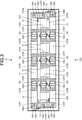
- FIG. 3 is a plan view of the storage battery device of the first embodiment, depicting a part below the radiator.
- the storage battery device 10 includes the battery management unit 13, thermally coupled to the radiator 14, on the front side in a plan view.
- the bus bars 161, the bus bar 16P, and the bus bar 16N are located in a part in which the battery management unit 13 is not placed and from the through holes 13TH formed in the substrate of the battery management unit 13.
- twelve battery cells 12 are connected in series between the bus bar 16P and the bus bar 16N.
- Each of the bus bars 161 is electrically connected to the battery management unit 13 via an electrical connection 16IT.
- bus bar 16P is electrically connected to the battery management unit 13 via an electrical connection 16PT while the bus bar 16N is electrically connected to the battery management unit 13 via an electrical connection 16NT.
- the bus bars 161, the bus bar 16P, and the bus bar 16N are connected to the positive-electrode-side cell charge and discharge terminals 12TP or the negative-electrode-side cell charge and discharge terminals 12TN of the battery cells 12 in bus bar openings 16H of a circular form by welding.
- the electrical connections 16IT, the electrical connection 16PT, and the electrical connection 16NT are electrically connected to the substrate of the battery management unit 13 by soldering or screwing.
- the battery management unit 13 performs charge and discharge management of each of the battery cells 12.
- FIG. 4 is an enlarged view of a part in which a heat conductive insulating member is disposed.
- the heat conductive member 18 is formed as, for example, an insulating sheet having a heat dissipation property (heat conductivity). As illustrated in FIG. 4 , the heat conductive member 18 tightly contacts the bus bar 16 and the radiator 14 fixed to the casing by compressive force applied from the radiator 14 side toward the bus bar 16. In this case, it is possible to apply adhesiveness to both sides of the heat conductive member 18 to improve ease of manufacturing (assembly).
- the heat conductive member 18 can be a thermally conductive adhesive.
- heat dissipation connections 16IC of the bus bars 161 serve to thermally couple the heat conductive members 18 to the radiator 14 in an insulated state via the through holes 13TH of the battery management unit 13.
- a heat dissipation connection 16PC of the bus bar 16P and a heat dissipation connection 16NC of the bus bar 16N serve to thermally couple the heat conductive members 18 to the radiator 14 in an insulated state in the part in which the substrate of the battery management unit 13 is not placed (possibly in the through holes 13TH).
- the heat dissipation connections 16IC of the bus bars 161, the heat dissipation connection 16PC of the bus bar 16P, and the heat dissipation connection 16NC of the bus bar 16N are set larger in width (vertical length in FIG. 3 ) than the rest of the bus bars 161, the bus bar 16P, and the bus bar 16N. This leads to enhancing the heat dissipation efficiency.
- the forms of the heat dissipation connections 16IC of the bus bars 161, the heat dissipation connection 16PC of the bus bar 16P, and the heat dissipation connection 16NC of the bus bar 16 N are not limited to the examples as above. Any structure can be suitably adopted as long as it can more efficiently dissipate heat toward the radiator 14.
- the bus bars 16 (the bus bars 161, the bus bar 16P, and the bus bar 16N) can be effectively cooled.
- the battery cells 12 can be effectively cooled via the positive-electrode-side cell charge and discharge terminals 12TP and the negative-electrode-side cell charge and discharge terminals 12TN.
- the battery cells 12 can each provide a higher output without an output limitation.
- the storage battery device can be made more compact in size. With the same device scale, a higher-output storage battery device can be provided.
- the second embodiment is different from the first embodiment in that electrode terminals (the positive-electrode-side cell charge and discharge terminals 12TP and the negative-electrode-side cell charge and discharge terminals 12TN) of the battery cells 12 are thermally coupled to the radiator 14, in place of the bus bars 16 thermally coupled to the radiator 14.
- electrode terminals the positive-electrode-side cell charge and discharge terminals 12TP and the negative-electrode-side cell charge and discharge terminals 12TN
- FIG. 5 is an explanatory diagram illustrating a schematic configuration of a storage battery device of the second embodiment.
- FIG. 5 the same or like constituents as in the first embodiment illustrated in FIG. 1 are denoted by the same reference numerals, and the detailed descriptions in the first embodiment will be incorporated.
- the radiator 14 has a tubular shape with a hollow part 14T and is provided with a plurality of protrusions 14P to be thermally coupled to the positive-electrode-side cell charge and discharge terminals 12TP and negative-electrode-side cell charge and discharge terminals 12TN of the battery cells 12.
- the substrate of the battery management unit 13 is provided with a plurality of through holes 13TH for ensuring a space in which the protrusions 14P are thermally coupled to the positive-electrode-side cell charge and discharge terminals 12TP and the negative-electrode-side cell charge and discharge terminals 12TN of the battery cells 12.
- Each of the heat conductive members 18 is disposed between the protrusion 14 and the positive-electrode-side cell charge and discharge terminal 12TP or the negative-electrode-side cell charge and discharge terminal 12TN of the cell 12 facing the protrusion 14.
- the heat conductive member 18 tightly contacts with the positive-electrode-side cell charge and discharge terminal 12TP or the negative-electrode-side cell charge and discharge terminal 12TN and the radiator 14 fixed to the casing by compressive force applied from the radiator 14 side toward the positive-electrode-side cell charge and discharge terminal 12TP or the negative-electrode-side cell charge and discharge terminal 12TN.
- the radiator 14 works to dissipate the heat of the battery cells 12 transmitted from the positive-electrode-side cell charge and discharge terminals 12TP or the negative-electrode-side cell charge and discharge terminals 12TN thermally coupled to the protrusions 14P, to thereby maintain the battery cells 12 at a given temperature or less.
- the radiator 14 dissipates the heat from the battery management unit 13 and the heat from the DC-DC converter 15 to thereby maintain the battery management unit 13 and the DC-DC converter 15 at their given temperatures or less.
- the positive-electrode-side cell charge and discharge terminals 12TP or the negative-electrode-side cell charge and discharge terminals 12TN of the battery cells 12 can be effectively cooled.
- the battery cells 12 can be effectively cooled via the positive-electrode-side cell charge and discharge terminals 12TP and the negative-electrode-side cell charge and discharge terminals 12TN.
- the battery cells 12 can each provide a higher output without an output limitation.
- the storage battery device can be made more compact in size. With the same device scale, a higher-output storage battery device can be provided.
- FIG. 6 is an explanatory diagram illustrating a schematic configuration of a storage battery device of the third embodiment.
- FIG. 6 the same or like constituents as in the first embodiment illustrated in FIG. 1 are denoted by the same reference numerals, and the detailed descriptions in the first embodiment will be incorporated.
- the third embodiment is different from the first embodiment in that the radiator 14 includes joints 21 at both ends of the hollow part 14T, and is connected to a coolant supply circulation system via the joints 21 to allow a coolant to flow into the hollow part 14T.
- the bus bars 16 (the bus bars 161, the bus bar 16P, and the bus bar 16N) of the third embodiment can be more effectively cooled than those of the first embodiment.
- the battery cells 12 can be effectively cooled via the positive-electrode-side cell charge and discharge terminals 12TP and the negative-electrode-side cell charge and discharge terminals 12TN.
- the battery cells 12 can each provide a higher output without an output limitation.
- FIG. 7 is an explanatory diagram illustrating a schematic configuration of a storage battery device of the fourth embodiment.
- FIG. 7 the same or like constituents as in the first embodiment illustrated in FIG. 1 are denoted by the same reference numerals, and the detailed descriptions in the first embodiment will be incorporated.
- the fourth embodiment is different from the first embodiment in that the radiator 14 includes an air blower 25 at one end of the hollow part 14T to forcibly supply air having passed through a filter 26 to the hollow part 14T and forcibly discharge the air via an opening at the other end of the hollow part 14T.
- the radiator 14 can collect the heat to more effectively cool the bus bars 16, the battery cells 12, the battery management unit 13, and the DC-DC converter 15. This makes it possible to further downsize the storage battery device or further heighten the output of the storage battery device.
- FIG. 8 is an explanatory diagram schematically illustrating a schematic configuration of a storage battery device of the fifth embodiment.
- FIG. 8 the same or like constituents as in the first embodiment illustrated in FIG. 1 are denoted by the same reference numerals, and the detailed descriptions in the first embodiment will be incorporated.
- the fifth embodiment is different from the first embodiment in including a heat pipe 30 in place of the radiator 14.
- the heat pipe 30 is provided with a wick inside, and the wick contains an operating fluid.
- the heat pipe 30 further includes an evaporator (heat-absorber) 30H thermally connected to the bus bars 16, the battery management unit 13, and the DC-DC converter 15, a heat insulator 301, and a condenser (heat dissipater) 30C connected to the evaporator 30H via the heat insulator 301 and provided with a radiator 31.
- evaporator heat-absorber
- condenser heat dissipater
- the evaporator 30H collects the heat from the bus bars 16, the battery cells 12, the battery management unit 13, and the DC-DC converter 15 by evaporation of the operating fluid, and the evaporated operating fluid rapidly flows to the condenser 30C.
- the operating fluid is then condensed by the condenser 30C to emit evaporative latent heat, and discharges the heat collected from the bus bars 16, the battery management unit 13, and the DC-DC converter 15 to outside the storage battery device 10.
- the operating fluid is then refluxed to the evaporator 30H by the capillary action of the wick.
- the heat pipe 30 can collect the heat to more effectively cool the bus bars 16, the battery cells 12, the battery management unit 13, and the DC-DC converter 15. This makes it possible to further downsize the storage battery device or further heighten the output of the storage battery device.
- the evaporator 30H heat dissipation surface
- the storage battery device is suitable for, for example, automobiles with a limited installation space.
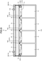
- FIG. 9 is an explanatory diagram schematically illustrating a schematic configuration of a storage battery device of a sixth embodiment.
- FIG. 9 the same or like constituents as in the first embodiment illustrated in FIG. 1 are denoted by the same reference numerals, and the detailed descriptions in the first embodiment will be incorporated.
- the sixth embodiment is different from the first embodiment in that heat dissipation connections (for example, heat dissipation connections 16IC, 16PC, and 16NC) of the bus bars 16 are electrically connected to the substrate of the battery management unit 13 using the conductivity of the heat conductive members 18, and are thermally coupled to the radiator 14 via the substrate of the battery management unit 13.
- heat dissipation connections for example, heat dissipation connections 16IC, 16PC, and 16NC
- bus bars 16 and the substrate of the battery management unit 13 are electrically and thermally connected together with a conductive adhesive, blade springs, or screws, for example.
- the radiator 14 can collect the heat of the bus bars 16 and the battery cells 12 via the substrate of the battery management unit 13.
- the bus bars 16, the battery cells 12, the battery management unit 13, and the DC-DC converter 15 can be more effectively cooled. This makes it possible to further downsize the storage battery device or further increase the output of the storage battery device.
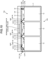
- FIG. 10 is an explanatory diagram illustrating a schematic configuration of a storage battery device of the seventh embodiment.
- FIG. 10 the same or like constituents as in the first embodiment illustrated in FIG. 1 are denoted by the same reference numerals.
- the seventh embodiment is different from the first embodiment in that the battery management unit 13 and the DC-DC converter 15 are disposed on the surface of the radiator 14 facing the cells 12, and the positive-electrode-side charge and discharge terminal 17P and the charge and discharge terminal 17N are disposed on the same lateral face of the casing.
- a storage battery device 10A generally includes a casing 11, battery cells (hereinafter simply referred to as cells) 12, a battery management unit 13, a radiator 14, a DC-DC converter 15, bus bars 16, a charge and discharge terminal 17N, and heat conductive members 18.
- the casing 11 is formed of a resin material, for example, and accommodates the battery cells 12, the battery management unit 13, the radiator 14, the DC-DC converter 15, the bus bars 16, and the heat conductive members 18.
- a positive-electrode-side charge and discharge terminal 17P and a charge and discharge terminal 17N protrude from the same lateral face (the left lateral face in FIG. 10 ).
- Each of the battery cells 12 includes a positive-electrode-side cell charge and discharge terminal 12TP and a negative-electrode-side cell charge and discharge terminal 12TN.
- FIG. 11 is a plan view of the storage battery device of the seventh embodiment, depicting a part below the radiator.
- the storage battery device 10A includes the battery management unit 13 thermally coupled to the radiator 14 on the front right side and the DC-DC converter 15 thermally coupled to the radiator 14 on the front left side in a plan view.
- Bus bars 161, a bus bar 16P, and a bus bar 16N are located in a part in which the battery management unit 13 is not placed, in the through holes 13TH formed in the substrate of the battery management unit 13, and in portions 15TH in which the DC-DC converter 15 is not placed.
- twelve battery cells 12 are connected in series between the bus bar 16P and the bus bar 16N.
- Each of the bus bars 161 is electrically connected to the battery management unit 13 via an electrical connection 16IT.
- bus bar 16P is electrically connected to the battery management unit 13 via an electrical connection 16PT while the bus bar 16N is electrically connected to the battery management unit 13 via an electrical connection 16NT.
- the battery management unit 13 performs charge and discharge management of each of the battery cells 12.
- heat dissipation connections 16IC of the bus bars 161 serve to thermally couple the heat conductive members 18 to the radiator 14 in an insulated state via the portions in which the battery management unit 13 is not placed, the through holes 13TH formed in the substrate of the battery management unit 13, and the portions 15TH in which the DC-DC converter 15 is not placed.
- a heat dissipation connection 16PC of the bus bar 16P and a heat dissipation connection 16NC of the bus bar 16N serve to thermally couple the heat conductive members 18 to the radiator 14 in an insulated state in the part in which the substrate of the DC-DC converter 15 is not placed (possibly in the portion in which the battery management unit 13 is not placed or in the through holes 13TH).
- the storage battery device of a more compact structure can effectively cool the battery management unit 13, the DC-DC converter 15, and the bus bars 16 (the bus bars 161, the bus bar 16P, and the bus bar 16N).
- the battery cells 12 can be effectively cooled via the positive-electrode-side cell charge and discharge terminals 12TP and the negative-electrode-side cell charge and discharge terminals 12TN.
- the battery cells 12 can each provide a higher output without an output limitation.
- the storage battery device can be made more compact in size. With the same device scale, a higher-output storage battery device can be provided.
- the substrate of the battery management unit 13 and the substrate of the DC-DC converter 15 are independent from each other.
- the battery management unit 13 and the DC-DC converter 15 can be disposed on the same substrate and be thermally coupled to the radiator 14.
- the above has not specifically described the bus bars 16 in terms of shape.
- the bus bars 16 can be increased in surface area so as to be able to dissipate more heat, or can have a larger contact area with the positive-electrode-side cell charge and discharge terminal 12TP and the negative-electrode-side cell charge and discharge terminal 12TN so as to reduce heat generation.
Landscapes
- Chemical & Material Sciences (AREA)
- Chemical Kinetics & Catalysis (AREA)
- Electrochemistry (AREA)
- General Chemical & Material Sciences (AREA)
- Engineering & Computer Science (AREA)
- Manufacturing & Machinery (AREA)
- Aviation & Aerospace Engineering (AREA)
- Microelectronics & Electronic Packaging (AREA)
- Battery Mounting, Suspending (AREA)
- Secondary Cells (AREA)
- Charge And Discharge Circuits For Batteries Or The Like (AREA)
- Electric Propulsion And Braking For Vehicles (AREA)
Abstract
Description
- Embodiments of the present invention relate to a storage battery device.
- Conventionally, storage battery devices have been used in various fields.
- The output voltage of battery cells constituting such a storage battery device is several volts. Thus, in order to generate a voltage of 48 V commonly employed in manufacturing or hybrid automobiles, for example, it is conceivable to connect a required number of battery cells in series or to boost the voltage thereof using a DC-DC converter.
-
- Patent Literature 1:
Japanese Patent Application Laid-open No. 2006-185863 - Patent Literature 2:
Japanese Patent Application Laid-open No. 2004-306726 - Patent Literature 3:
Japanese Patent Application Laid-open No. 2016-220363 - Patent Literature 4:
Japanese Patent Application Laid-open No. 2019-016564 - In the case of using a DC-DC converter, when the output voltage 24 V of an assembled battery is boosted twice to 48 V for use in industrial machines or hybrid automobiles for output, for example, a current flowing through the assembled battery is double or more an output current.
- In this case, heat generation due to copper loss is in proportion to the square of a current by the Ohm's law, so that the amount of heat from the current path in the assembled battery quadruples.
- Furthermore, the storage battery device typically tolerates a flow of a large current temporarily in view of a variation in load. However, a current-path member serving as a charge and discharge path, such as a terminal and a bus bar, has a smaller thermal time constant than the battery cells filled with battery materials. Because of this, the current-path member rapidly increases in temperature due to a temporary great current.
- Thus, the storage battery device incorporating a DC-DC converter, in which a current flowing through the assembled battery is several times as large as an output current, is requested to promptly remove temporarily generated heat in the current-path member.
- In view of the above, an object of the present invention is to provide a storage battery device with a higher output that efficiently cools a current-path member and can be easily downsized.
- According to an embodiment, a storage battery device includes a cell unit including a plurality of battery cells; a current-path member that forms a current path through which electric power is supplied from or to the battery cells; and a radiator thermally coupled to the current-path member.
-
-
FIG. 1 is an explanatory diagram illustrating a schematic configuration of a storage battery device according to a first embodiment; -
FIG. 2 is a block diagram illustrating a control system configuration of a storage battery device of an embodiment; -
FIG. 3 is a plan view of the storage battery device of the first embodiment, depicting a part below a radiator; -
FIG. 4 is an enlarged view of a part in which a heat conductive insulating member is disposed; -
FIG. 5 is an explanatory diagram illustrating a schematic configuration of a storage battery device according to a second embodiment; -
FIG. 6 is an explanatory diagram illustrating a schematic configuration of a storage battery device according to a third embodiment; -
FIG. 7 is an explanatory diagram illustrating a schematic configuration of a storage battery device according to a fourth embodiment; -
FIG. 8 is an explanatory diagram illustrating a schematic configuration of a storage battery device according to a fifth embodiment; -
FIG. 9 is an explanatory diagram illustrating a schematic configuration of a storage battery device according to a sixth embodiment; -
FIG. 10 is an explanatory diagram illustrating a schematic configuration of a storage battery device according to a seventh embodiment; and -
FIG. 11 is a plan view of the storage battery device according to the seventh embodiment, depicting a part below a radiator. - Next, preferable embodiments will be described in detail with reference to the accompanying drawings.
- The following will describe a storage battery device installed in an automatic guided vehicle (AGV) as an example of storage battery devices of embodiments, however, it is not limited thereto.
-
FIG. 1 is an explanatory diagram illustrating a schematic configuration of a storage battery device according to a first embodiment. - A
storage battery device 10 generally include acasing 11, battery cells (hereinafter simply referred to as cells) 12, abattery management unit 13, aradiator 14, a DC-DC converter 15,bus bars 16, a charge anddischarge terminal 17N, and heatconductive members 18. - The
battery cells 12 are electrically connected to one another and constitute acell unit 12U as a whole. - The
casing 11 is formed of a resin material, for example, and accommodates thebattery cells 12, thebattery management unit 13, theradiator 14, the DC-DC converter 15, thebus bars 16, the heatconductive members 18, a positive-electrode-side charge anddischarge terminal 17P, and a charge anddischarge terminal 17N. The positive-electrode-side charge anddischarge terminal 17P and the charge anddischarge terminal 17N protrude from thecasing 11. - Each of the
battery cells 12 includes a positive-electrode-side cell charge and discharge terminal 12TP and a negative-electrode-side cell charge and discharge terminal 12TN. -
FIG. 2 is a block diagram illustrating a control system configuration of a storage battery device according to an embodiment. - The
battery management unit 13 is configured to be initiated by a start signal SWU from a not-illustrated controller in the vehicle body of the automatic guided vehicle, and to be able to exchange communication data COM with the controller via a communication line. - The
battery management unit 13 also serves to detect the voltages and temperatures of thebattery cells 12 to perform charge and discharge management, and output a control signal SC to the DC-DC converter 15 to interrupt a current from a main circuit (circuit in the automatic guided vehicle), if necessary. - In this case, as illustrated in
FIG. 1 , the substrate of thebattery management unit 13 is provided with a plurality of through holes 13TH for ensuring a space in which thebus bars 16 are thermally coupled to theradiator 14. - The
radiator 14 has a tubular shape with ahollow part 14T, and serves to dissipate heat transmitted from thebattery cells 12 via thebus bars 16, heat from thebattery management unit 13, and heat from the DC-DC converter 15, to thereby maintain thebattery cells 12, thebattery management unit 13, and the DC-DC converter 15 at their given temperatures or less. - As described above, the
bus bars 16 and the DC-DC converter 15 are disposed to face each other across theradiator 14. - Thus, by allowing a sufficient amount of a coolant to flow into the
hollow part 14T, the heat occurring from both thebus bars 16 and the DC-DC converter 15 is removed, which can prevent transmission of the heat between them via theradiator 14 to affect each other. - The DC-
DC converter 15 serves to supply charging power to thebattery cells 12 from a not-illustrated charging device which is connected to the automatic guided vehicle body via the positive-electrode-side charge anddischarge terminal 17P and the charge anddischarge terminal 17N. - The DC-
DC converter 15 also boosts the voltage of discharged power from thebattery cells 12 and supply it to the automatic guided vehicle body via the positive-electrode-side charge anddischarge terminal 17P and the charge anddischarge terminal 17N. - Further, the DC-
DC converter 15 interrupts a current in response to receipt of the control signal SC from thebattery management unit 13. - The
bus bars 16 generally includebus bars 161 that connect between two battery cells 12 (between the positive-electrode-side cell charge and discharge terminal 12TP of onecell 12 and the negative-electrode-side cell charge and discharge terminal 12TN of another cell 12); abus bar 16P that connects a positive-electrode-side cell charge and discharge terminal 12TP of thecell 12 closest to the high potential side and a high potential-side terminal (not illustrated) of the DC-DC converter 15, and abus bar 16N that connects the negative-electrode-side cell charge and discharge terminal 12TN of thecell 12 closest to the low potential side and a lower potential-side terminal (not illustrated) of the DC-DC converter 15. -
FIG. 3 is a plan view of the storage battery device of the first embodiment, depicting a part below the radiator. - The
storage battery device 10 includes thebattery management unit 13, thermally coupled to theradiator 14, on the front side in a plan view. Thebus bars 161, thebus bar 16P, and thebus bar 16N are located in a part in which thebattery management unit 13 is not placed and from the through holes 13TH formed in the substrate of thebattery management unit 13. - In the example of
FIG. 3 , twelvebattery cells 12 are connected in series between thebus bar 16P and thebus bar 16N. - Each of the
bus bars 161 is electrically connected to thebattery management unit 13 via an electrical connection 16IT. - Similarly, the
bus bar 16P is electrically connected to thebattery management unit 13 via an electrical connection 16PT while thebus bar 16N is electrically connected to thebattery management unit 13 via an electrical connection 16NT. - In such a case, in the example of
FIG. 3 , thebus bars 161, thebus bar 16P, and thebus bar 16N are connected to the positive-electrode-side cell charge and discharge terminals 12TP or the negative-electrode-side cell charge and discharge terminals 12TN of thebattery cells 12 inbus bar openings 16H of a circular form by welding. - Further, the electrical connections 16IT, the electrical connection 16PT, and the electrical connection 16NT are electrically connected to the substrate of the
battery management unit 13 by soldering or screwing. - Thus, the
battery management unit 13 performs charge and discharge management of each of thebattery cells 12. -
FIG. 4 is an enlarged view of a part in which a heat conductive insulating member is disposed. - The heat
conductive member 18 is formed as, for example, an insulating sheet having a heat dissipation property (heat conductivity). As illustrated inFIG. 4 , the heatconductive member 18 tightly contacts thebus bar 16 and theradiator 14 fixed to the casing by compressive force applied from theradiator 14 side toward thebus bar 16. In this case, it is possible to apply adhesiveness to both sides of the heatconductive member 18 to improve ease of manufacturing (assembly). - In the case of using the
radiator 14 with insulating properties, such as the one having an insulating resin film or insulating ceramics (for example, aluminum nitride) formed on the surface or the one formed from an insulating material, the heatconductive member 18 can be a thermally conductive adhesive. - In the first embodiment, as illustrated in
FIG. 1 , heat dissipation connections 16IC of the bus bars 161 serve to thermally couple the heatconductive members 18 to theradiator 14 in an insulated state via the through holes 13TH of thebattery management unit 13. - Similarly, as illustrated in
FIG. 1 , a heat dissipation connection 16PC of thebus bar 16P and a heat dissipation connection 16NC of thebus bar 16N serve to thermally couple the heatconductive members 18 to theradiator 14 in an insulated state in the part in which the substrate of thebattery management unit 13 is not placed (possibly in the through holes 13TH). - The heat dissipation connections 16IC of the bus bars 161, the heat dissipation connection 16PC of the
bus bar 16P, and the heat dissipation connection 16NC of thebus bar 16N are set larger in width (vertical length inFIG. 3 ) than the rest of the bus bars 161, thebus bar 16P, and thebus bar 16N. This leads to enhancing the heat dissipation efficiency. - The forms of the heat dissipation connections 16IC of the bus bars 161, the heat dissipation connection 16PC of the
bus bar 16P, and the heat dissipation connection 16NC of thebus bar 16 N are not limited to the examples as above. Any structure can be suitably adopted as long as it can more efficiently dissipate heat toward theradiator 14. - According to the first embodiment, the bus bars 16 (the bus bars 161, the
bus bar 16P, and thebus bar 16N) can be effectively cooled. As a result, thebattery cells 12 can be effectively cooled via the positive-electrode-side cell charge and discharge terminals 12TP and the negative-electrode-side cell charge and discharge terminals 12TN. Thereby, thebattery cells 12 can each provide a higher output without an output limitation. - That is, with the same output, the storage battery device can be made more compact in size. With the same device scale, a higher-output storage battery device can be provided.
- Next, a second embodiment will be described.
- The second embodiment is different from the first embodiment in that electrode terminals (the positive-electrode-side cell charge and discharge terminals 12TP and the negative-electrode-side cell charge and discharge terminals 12TN) of the
battery cells 12 are thermally coupled to theradiator 14, in place of the bus bars 16 thermally coupled to theradiator 14. -
FIG. 5 is an explanatory diagram illustrating a schematic configuration of a storage battery device of the second embodiment. - In
FIG. 5 , the same or like constituents as in the first embodiment illustrated inFIG. 1 are denoted by the same reference numerals, and the detailed descriptions in the first embodiment will be incorporated. - The
radiator 14 has a tubular shape with ahollow part 14T and is provided with a plurality ofprotrusions 14P to be thermally coupled to the positive-electrode-side cell charge and discharge terminals 12TP and negative-electrode-side cell charge and discharge terminals 12TN of thebattery cells 12. - The substrate of the
battery management unit 13 is provided with a plurality of through holes 13TH for ensuring a space in which theprotrusions 14P are thermally coupled to the positive-electrode-side cell charge and discharge terminals 12TP and the negative-electrode-side cell charge and discharge terminals 12TN of thebattery cells 12. - Each of the heat
conductive members 18 is disposed between theprotrusion 14 and the positive-electrode-side cell charge and discharge terminal 12TP or the negative-electrode-side cell charge and discharge terminal 12TN of thecell 12 facing theprotrusion 14. The heatconductive member 18 tightly contacts with the positive-electrode-side cell charge and discharge terminal 12TP or the negative-electrode-side cell charge and discharge terminal 12TN and theradiator 14 fixed to the casing by compressive force applied from theradiator 14 side toward the positive-electrode-side cell charge and discharge terminal 12TP or the negative-electrode-side cell charge and discharge terminal 12TN. - As a result, the
radiator 14 works to dissipate the heat of thebattery cells 12 transmitted from the positive-electrode-side cell charge and discharge terminals 12TP or the negative-electrode-side cell charge and discharge terminals 12TN thermally coupled to theprotrusions 14P, to thereby maintain thebattery cells 12 at a given temperature or less. - In parallel with the above, the
radiator 14 dissipates the heat from thebattery management unit 13 and the heat from the DC-DC converter 15 to thereby maintain thebattery management unit 13 and the DC-DC converter 15 at their given temperatures or less. - According to the second embodiment, the positive-electrode-side cell charge and discharge terminals 12TP or the negative-electrode-side cell charge and discharge terminals 12TN of the
battery cells 12 can be effectively cooled. As a result, thebattery cells 12 can be effectively cooled via the positive-electrode-side cell charge and discharge terminals 12TP and the negative-electrode-side cell charge and discharge terminals 12TN. Thereby, thebattery cells 12 can each provide a higher output without an output limitation. - Thus, according to the second embodiment, with the same output, the storage battery device can be made more compact in size. With the same device scale, a higher-output storage battery device can be provided.
- Next, a third embodiment will be described.
-
FIG. 6 is an explanatory diagram illustrating a schematic configuration of a storage battery device of the third embodiment. - In
FIG. 6 , the same or like constituents as in the first embodiment illustrated inFIG. 1 are denoted by the same reference numerals, and the detailed descriptions in the first embodiment will be incorporated. - The third embodiment is different from the first embodiment in that the
radiator 14 includes joints 21 at both ends of thehollow part 14T, and is connected to a coolant supply circulation system via the joints 21 to allow a coolant to flow into thehollow part 14T. - Owing to such a configuration, the bus bars 16 (the bus bars 161, the
bus bar 16P, and thebus bar 16N) of the third embodiment can be more effectively cooled than those of the first embodiment. As a result, thebattery cells 12 can be effectively cooled via the positive-electrode-side cell charge and discharge terminals 12TP and the negative-electrode-side cell charge and discharge terminals 12TN. Thereby, thebattery cells 12 can each provide a higher output without an output limitation. - This leads to further downsizing the storage battery device or further heightening the output of the storage battery device.
- Next, a fourth embodiment will be described.
-
FIG. 7 is an explanatory diagram illustrating a schematic configuration of a storage battery device of the fourth embodiment. - In
FIG. 7 , the same or like constituents as in the first embodiment illustrated inFIG. 1 are denoted by the same reference numerals, and the detailed descriptions in the first embodiment will be incorporated. - The fourth embodiment is different from the first embodiment in that the
radiator 14 includes anair blower 25 at one end of thehollow part 14T to forcibly supply air having passed through afilter 26 to thehollow part 14T and forcibly discharge the air via an opening at the other end of thehollow part 14T. - Owing to such a configuration, the
radiator 14 can collect the heat to more effectively cool the bus bars 16, thebattery cells 12, thebattery management unit 13, and the DC-DC converter 15. This makes it possible to further downsize the storage battery device or further heighten the output of the storage battery device. - Next, a fifth embodiment will be described.
-
FIG. 8 is an explanatory diagram schematically illustrating a schematic configuration of a storage battery device of the fifth embodiment. - In
FIG. 8 , the same or like constituents as in the first embodiment illustrated inFIG. 1 are denoted by the same reference numerals, and the detailed descriptions in the first embodiment will be incorporated. - The fifth embodiment is different from the first embodiment in including a
heat pipe 30 in place of theradiator 14. - The
heat pipe 30 is provided with a wick inside, and the wick contains an operating fluid. - The
heat pipe 30 further includes an evaporator (heat-absorber) 30H thermally connected to the bus bars 16, thebattery management unit 13, and the DC-DC converter 15, aheat insulator 301, and a condenser (heat dissipater) 30C connected to theevaporator 30H via theheat insulator 301 and provided with aradiator 31. - By the configuration as above, the
evaporator 30H collects the heat from the bus bars 16, thebattery cells 12, thebattery management unit 13, and the DC-DC converter 15 by evaporation of the operating fluid, and the evaporated operating fluid rapidly flows to thecondenser 30C. - The operating fluid is then condensed by the
condenser 30C to emit evaporative latent heat, and discharges the heat collected from the bus bars 16, thebattery management unit 13, and the DC-DC converter 15 to outside thestorage battery device 10. - The operating fluid is then refluxed to the
evaporator 30H by the capillary action of the wick. - As described above, the
heat pipe 30 can collect the heat to more effectively cool the bus bars 16, thebattery cells 12, thebattery management unit 13, and the DC-DC converter 15. This makes it possible to further downsize the storage battery device or further heighten the output of the storage battery device. - In addition, the
evaporator 30H (heat dissipation surface) can be placed at any location, therefore, the storage battery device is suitable for, for example, automobiles with a limited installation space. -
FIG. 9 is an explanatory diagram schematically illustrating a schematic configuration of a storage battery device of a sixth embodiment. - In
FIG. 9 , the same or like constituents as in the first embodiment illustrated inFIG. 1 are denoted by the same reference numerals, and the detailed descriptions in the first embodiment will be incorporated. - The sixth embodiment is different from the first embodiment in that heat dissipation connections (for example, heat dissipation connections 16IC, 16PC, and 16NC) of the bus bars 16 are electrically connected to the substrate of the
battery management unit 13 using the conductivity of the heatconductive members 18, and are thermally coupled to theradiator 14 via the substrate of thebattery management unit 13. - In this case, the bus bars 16 and the substrate of the
battery management unit 13 are electrically and thermally connected together with a conductive adhesive, blade springs, or screws, for example. - Owing to such a configuration, the
radiator 14 can collect the heat of the bus bars 16 and thebattery cells 12 via the substrate of thebattery management unit 13. - Thus, according to the sixth embodiment, the bus bars 16, the
battery cells 12, thebattery management unit 13, and the DC-DC converter 15 can be more effectively cooled. This makes it possible to further downsize the storage battery device or further increase the output of the storage battery device. - Next, a seventh embodiment will be described.
-
FIG. 10 is an explanatory diagram illustrating a schematic configuration of a storage battery device of the seventh embodiment. - In
FIG. 10 , the same or like constituents as in the first embodiment illustrated inFIG. 1 are denoted by the same reference numerals. - The seventh embodiment is different from the first embodiment in that the
battery management unit 13 and the DC-DC converter 15 are disposed on the surface of theradiator 14 facing thecells 12, and the positive-electrode-side charge and discharge terminal 17P and the charge anddischarge terminal 17N are disposed on the same lateral face of the casing. - A
storage battery device 10A generally includes acasing 11, battery cells (hereinafter simply referred to as cells) 12, abattery management unit 13, aradiator 14, a DC-DC converter 15, bus bars 16, a charge and discharge terminal 17N, and heatconductive members 18. - The
casing 11 is formed of a resin material, for example, and accommodates thebattery cells 12, thebattery management unit 13, theradiator 14, the DC-DC converter 15, the bus bars 16, and the heatconductive members 18. A positive-electrode-side charge and discharge terminal 17P and a charge anddischarge terminal 17N protrude from the same lateral face (the left lateral face inFIG. 10 ). - Each of the
battery cells 12 includes a positive-electrode-side cell charge and discharge terminal 12TP and a negative-electrode-side cell charge and discharge terminal 12TN. -
FIG. 11 is a plan view of the storage battery device of the seventh embodiment, depicting a part below the radiator. - The
storage battery device 10A includes thebattery management unit 13 thermally coupled to theradiator 14 on the front right side and the DC-DC converter 15 thermally coupled to theradiator 14 on the front left side in a plan view. - Bus bars 161, a
bus bar 16P, and abus bar 16N are located in a part in which thebattery management unit 13 is not placed, in the through holes 13TH formed in the substrate of thebattery management unit 13, and in portions 15TH in which the DC-DC converter 15 is not placed. - In the example of
FIG. 11 , twelvebattery cells 12 are connected in series between thebus bar 16P and thebus bar 16N. - Each of the bus bars 161 is electrically connected to the
battery management unit 13 via an electrical connection 16IT. - Similarly, the
bus bar 16P is electrically connected to thebattery management unit 13 via an electrical connection 16PT while thebus bar 16N is electrically connected to thebattery management unit 13 via an electrical connection 16NT. - Thus, the
battery management unit 13 performs charge and discharge management of each of thebattery cells 12. - In the seventh embodiment, as illustrated in
FIG. 10 , heat dissipation connections 16IC of the bus bars 161 serve to thermally couple the heatconductive members 18 to theradiator 14 in an insulated state via the portions in which thebattery management unit 13 is not placed, the through holes 13TH formed in the substrate of thebattery management unit 13, and the portions 15TH in which the DC-DC converter 15 is not placed. - Similarly, as illustrated in
FIG. 1 , a heat dissipation connection 16PC of thebus bar 16P and a heat dissipation connection 16NC of thebus bar 16N serve to thermally couple the heatconductive members 18 to theradiator 14 in an insulated state in the part in which the substrate of the DC-DC converter 15 is not placed (possibly in the portion in which thebattery management unit 13 is not placed or in the through holes 13TH). - In this case, as indicated by the arrow in
FIG. 10 , it is preferable to allow a coolant to flow from thebattery management unit 13 generating less heat to the DC-DC converter 15 generating more heat, which can implement more efficient cooling. - According to the seventh embodiment as described above, the storage battery device of a more compact structure can effectively cool the
battery management unit 13, the DC-DC converter 15, and the bus bars 16 (the bus bars 161, thebus bar 16P, and thebus bar 16N). As a result, thebattery cells 12 can be effectively cooled via the positive-electrode-side cell charge and discharge terminals 12TP and the negative-electrode-side cell charge and discharge terminals 12TN. Thereby, thebattery cells 12 can each provide a higher output without an output limitation. - That is, with the same output, the storage battery device can be made more compact in size. With the same device scale, a higher-output storage battery device can be provided.
- The above has described the example that the substrate of the
battery management unit 13 and the substrate of the DC-DC converter 15 are independent from each other. However, thebattery management unit 13 and the DC-DC converter 15 can be disposed on the same substrate and be thermally coupled to theradiator 14. - The above has not specifically described the bus bars 16 in terms of shape. The bus bars 16 can be increased in surface area so as to be able to dissipate more heat, or can have a larger contact area with the positive-electrode-side cell charge and discharge terminal 12TP and the negative-electrode-side cell charge and discharge terminal 12TN so as to reduce heat generation.
- The above has described the example that the plurality of
battery cells 12 is connected in series to constitute thecell unit 12U, however, this is not limiting. It is possible to connect the plurality ofbattery cells 12 in series-parallel to constitute thecell unit 12U. - While certain embodiments have been described, these embodiments have been presented by way of example only, and are not intended to limit the scope of the inventions. Indeed, the novel methods and systems described herein may be embodied in different other forms; furthermore, various omissions, substitutions and varies in the form of the methods and systems described herein may be made without departing from the spirit of the inventions. The accompanying claims and their equivalents are intended to cover such forms or modifications as would fall within the scope and spirit of the inventions.
-
- 10, 10A Storage battery device
- 11 Casing
- 12 Cell
- 12TN Negative-electrode-side cell charge and discharge terminal
- 12TP Positive-electrode-side cell charge and discharge terminal
- 12U Cell unit
- 13 Battery management unit
- 13TH Through hole
- 14 Radiator
- 14P Protrusion
- 14T Hollow part
- 15 DC converter
- 16 Bus bar
- 16H Bus bar opening
- 16I Bus bar
- 16IC Heat dissipation connection
- 16IT Electrical connection
- 16N Bus bar
- 16NC Heat dissipation connection
- 16NT Electrical connection
- 16P Bus bar
- 16PC Heat dissipation connection
- 16PT Electrical connection
- 17N Negative-electrode-side charge and discharge terminal
- 17P Positive-electrode-side charge and discharge terminal
- 18 Heat conductive member
- 21 Joint
- 26 Filter
- 30 Heat pipe
Claims (10)
- A storage battery device, comprising:a cell unit comprising a plurality of battery cells;a current-path member that forms a current path through which electric power is supplied from or to the battery cells; anda radiator thermally coupled to the current-path member.
- The storage battery device according to claim 1, whereinthe current-path member includes a bus bar that connects the battery cells to each other, andthe radiator is thermally coupled to the bus bar connecting the battery cells to each other.
- The storage battery device according to claim 1, whereinthe current-path member includes a positive-electrode-side terminal and a negative-electrode-side terminal that are included in each of the battery cells, andthe radiator is thermally coupled to the positive-electrode-side terminal and the negative-electrode-side terminal.
- The storage battery device according to claim 1, further comprising:a DC-DC converter electrically connected to the cell unit via the current-path member, the DC-DC converter configured to boost a voltage of electric power of the cell unit for output, and step down a voltage of external electric power for output to the cell unit, whereinthe radiator is thermally coupled to the DC-DC converter.
- The storage battery device according to claim 4, whereinthe current-path member includes a bus bar that connects the cell unit to the DC-DC converter, andthe radiator is thermally coupled to the bus bar connecting the cell unit to the DC-DC converter.
- The storage battery device according to claim 2, further comprising:a battery management unit electrically connected to the bus bar connecting the battery cells to each other, the battery management unit configured to manage the cell unit, whereinthe radiator is thermally coupled to the battery management unit.
- The storage battery device according to claim 1, wherein
the radiator has a hollow part that allows a coolant to flow through an inside thereof. - The storage battery device according to claim 7, further comprising:
an air blower configured to blow cooling air as the coolant to the radiator. - The storage battery device according to claim 4, further comprising:a battery management unit electrically connected to a bus bar that connects the battery cells to each other, the battery management unit configured to manage the cell unit, whereinthe radiator has a hollow part that allows a coolant to flow through an inside thereof, andthe DC-DC converter and the battery management unit are disposed in opposing sides of the radiator via the hollow part and are thermally coupled to the radiator.
- The storage battery device according to claim 1, wherein
the radiator includes a heat pipe.
Applications Claiming Priority (2)
| Application Number | Priority Date | Filing Date | Title |
|---|---|---|---|
| JP2019091488A JP7155064B2 (en) | 2019-05-14 | 2019-05-14 | Storage battery device |
| PCT/JP2019/034861 WO2020230344A1 (en) | 2019-05-14 | 2019-09-04 | Storage battery device |
Publications (2)
| Publication Number | Publication Date |
|---|---|
| EP3972033A1 true EP3972033A1 (en) | 2022-03-23 |
| EP3972033A4 EP3972033A4 (en) | 2024-01-24 |
Family
ID=73221984
Family Applications (1)
| Application Number | Title | Priority Date | Filing Date |
|---|---|---|---|
| EP19928846.5A Pending EP3972033A4 (en) | 2019-05-14 | 2019-09-04 | Storage battery device |
Country Status (5)
| Country | Link |
|---|---|
| US (1) | US12183903B2 (en) |
| EP (1) | EP3972033A4 (en) |
| JP (1) | JP7155064B2 (en) |
| CN (1) | CN113544899A (en) |
| WO (1) | WO2020230344A1 (en) |
Cited By (2)
| Publication number | Priority date | Publication date | Assignee | Title |
|---|---|---|---|---|
| EP4425648A1 (en) * | 2022-12-14 | 2024-09-04 | TVS Motor Company Limited | A battery pack |
| EP4443605A1 (en) * | 2023-04-03 | 2024-10-09 | Eve Energy Co., Ltd. | Battery pack and unmanned aerial vehicle |
Families Citing this family (2)
| Publication number | Priority date | Publication date | Assignee | Title |
|---|---|---|---|---|
| US12315957B2 (en) * | 2021-10-01 | 2025-05-27 | Atieva, Inc. | Multi-axis ultrasonic wedge wire bonding |
| WO2025032599A1 (en) * | 2023-08-10 | 2025-02-13 | Tvs Motor Company Limited | An energy storage assembly and a battery unit |
Family Cites Families (26)
| Publication number | Priority date | Publication date | Assignee | Title |
|---|---|---|---|---|
| JP3869585B2 (en) * | 1999-07-30 | 2007-01-17 | 三洋電機株式会社 | Discharge method of multiple secondary batteries and assembled battery |
| JP2004306726A (en) | 2003-04-04 | 2004-11-04 | Toyota Motor Corp | Battery pack cooling structure |
| JP4710320B2 (en) | 2004-12-28 | 2011-06-29 | トヨタ自動車株式会社 | Vehicle battery pack mounting structure |
| JP2006216303A (en) | 2005-02-02 | 2006-08-17 | Denso Corp | Heating equipment cooling structure |
| JP5119575B2 (en) | 2005-05-11 | 2013-01-16 | 日産自動車株式会社 | Battery module and temperature control method thereof |
| US20060261783A1 (en) * | 2005-05-23 | 2006-11-23 | Paul Gamboa | Electronic battery module (EBM) with bidirectional DC-DC converter |
| JP4661895B2 (en) * | 2008-04-02 | 2011-03-30 | 株式会社デンソー | Battery cooling device |
| JP2011009402A (en) | 2009-06-25 | 2011-01-13 | Panasonic Corp | Electricity accumulation unit |
| DE102009035458A1 (en) * | 2009-07-31 | 2011-02-03 | Daimler Ag | Battery i.e. heavy-duty traction battery, for use in e.g. electric vehicle, has high-voltage electric circuit including electrical and electronic components and bus bars that are thermally connected with actively cooled cooling device |
| JP5417162B2 (en) * | 2009-12-28 | 2014-02-12 | 株式会社日立製作所 | Power storage device |
| KR101084224B1 (en) * | 2010-06-10 | 2011-11-17 | 에스비리모티브 주식회사 | Battery pack |
| JP2012084318A (en) * | 2010-10-08 | 2012-04-26 | Auto Network Gijutsu Kenkyusho:Kk | Bus bar module |
| DE102011003964A1 (en) * | 2011-02-11 | 2012-08-16 | Sb Limotive Company Ltd. | Lid, battery module, battery and motor vehicle |
| JP2012216360A (en) * | 2011-03-31 | 2012-11-08 | Sanyo Electric Co Ltd | Battery module |
| WO2012150629A1 (en) * | 2011-05-02 | 2012-11-08 | トヨタ自動車株式会社 | Fuel cell vehicle |
| JP2015115275A (en) * | 2013-12-13 | 2015-06-22 | 株式会社東芝 | Battery module |
| US9397328B2 (en) * | 2014-01-22 | 2016-07-19 | Ford Global Technologies, Llc | Flexible busbar holder for welded cells |
| WO2015125281A1 (en) * | 2014-02-21 | 2015-08-27 | 株式会社日立製作所 | Power module, power conversion device, and railroad vehicle |
| JP6312474B2 (en) | 2014-03-19 | 2018-04-18 | 三洋電機株式会社 | Vehicle power supply system |
| US10084218B2 (en) | 2014-05-09 | 2018-09-25 | Lg Chem, Ltd. | Battery pack and method of assembling the battery pack |
| WO2016157263A1 (en) | 2015-03-31 | 2016-10-06 | 三洋電機株式会社 | Power supply device and vehicle provided with same |
| JP6533694B2 (en) | 2015-05-19 | 2019-06-19 | 矢崎総業株式会社 | Power supply |
| KR102022590B1 (en) * | 2015-09-21 | 2019-09-18 | 주식회사 엘지화학 | Battery Module |
| WO2017073258A1 (en) * | 2015-10-27 | 2017-05-04 | 株式会社オートネットワーク技術研究所 | Power storage unit |
| JP6693480B2 (en) * | 2017-06-22 | 2020-05-13 | 株式会社デンソー | Terminal cooling device |
| JP6787263B2 (en) | 2017-07-10 | 2020-11-18 | トヨタ自動車株式会社 | Power supply |
-
2019
- 2019-05-14 JP JP2019091488A patent/JP7155064B2/en active Active
- 2019-09-04 EP EP19928846.5A patent/EP3972033A4/en active Pending
- 2019-09-04 WO PCT/JP2019/034861 patent/WO2020230344A1/en not_active Ceased
- 2019-09-04 CN CN201980093716.1A patent/CN113544899A/en active Pending
-
2021
- 2021-11-04 US US17/518,681 patent/US12183903B2/en active Active
Cited By (2)
| Publication number | Priority date | Publication date | Assignee | Title |
|---|---|---|---|---|
| EP4425648A1 (en) * | 2022-12-14 | 2024-09-04 | TVS Motor Company Limited | A battery pack |
| EP4443605A1 (en) * | 2023-04-03 | 2024-10-09 | Eve Energy Co., Ltd. | Battery pack and unmanned aerial vehicle |
Also Published As
| Publication number | Publication date |
|---|---|
| CN113544899A (en) | 2021-10-22 |
| EP3972033A4 (en) | 2024-01-24 |
| US20220059883A1 (en) | 2022-02-24 |
| WO2020230344A1 (en) | 2020-11-19 |
| JP2020187915A (en) | 2020-11-19 |
| JP7155064B2 (en) | 2022-10-18 |
| US12183903B2 (en) | 2024-12-31 |
Similar Documents
| Publication | Publication Date | Title |
|---|---|---|
| US12183903B2 (en) | Storage battery device | |
| JP6637765B2 (en) | Thermoelectric based thermal management system | |
| CN113544897B (en) | Cooling system for cooling battery module, high voltage battery and motor vehicle | |
| US20200227801A1 (en) | Active rechargeable battery thermal management system | |
| CN111355005B (en) | Assembly for electrical connection and battery pack or vehicle | |
| CN104756308A (en) | Battery system and motor vehicle | |
| JP2018207718A (en) | Electric power conversion system | |
| KR102786035B1 (en) | Vehicles, and power conversion devices for vehicles | |
| CN106712460B (en) | Power converter | |
| CN111727527B (en) | Battery modules, battery packs including battery modules and vehicles including battery packs | |
| EP3396801B1 (en) | High voltage terminal cooling structure | |
| JP2019068730A (en) | Compact type inverter and motor vehicle with the same | |
| KR20190084849A (en) | Switchable battery module | |
| KR101932052B1 (en) | Insulator and connector for thermoelectric devices in a thermoelectric assembly | |
| JP5169092B2 (en) | Power converter | |
| US20220069386A1 (en) | Battery Pack with Integrated Thermal Management | |
| US6555260B2 (en) | Fuel cell system having a fuel cell stack with integrated polarity reversal protection diode | |
| CN112313869A (en) | Power conversion device | |
| CN119674312A (en) | Battery Cell | |
| EP4273997A1 (en) | A battery stack with a thermal power dissipation system | |
| JP2014096881A (en) | Inverter device | |
| CN223023337U (en) | Battery pack breaking unit, battery pack and vehicle | |
| CN121439959A (en) | The two components of the transport vehicle are thermally coupled via heat pipes. | |
| CN121753487A (en) | Electrical connection box for a battery, battery and motor vehicle | |
| CN119452747A (en) | Power supply and distribution system of vehicle and vehicle |
Legal Events
| Date | Code | Title | Description |
|---|---|---|---|
| STAA | Information on the status of an ep patent application or granted ep patent |
Free format text: STATUS: THE INTERNATIONAL PUBLICATION HAS BEEN MADE |
|
| PUAI | Public reference made under article 153(3) epc to a published international application that has entered the european phase |
Free format text: ORIGINAL CODE: 0009012 |
|
| STAA | Information on the status of an ep patent application or granted ep patent |
Free format text: STATUS: REQUEST FOR EXAMINATION WAS MADE |
|
| 17P | Request for examination filed |
Effective date: 20210901 |
|
| AK | Designated contracting states |
Kind code of ref document: A1 Designated state(s): AL AT BE BG CH CY CZ DE DK EE ES FI FR GB GR HR HU IE IS IT LI LT LU LV MC MK MT NL NO PL PT RO RS SE SI SK SM TR |
|
| DAV | Request for validation of the european patent (deleted) | ||
| DAX | Request for extension of the european patent (deleted) | ||
| A4 | Supplementary search report drawn up and despatched |
Effective date: 20240103 |
|
| RIC1 | Information provided on ipc code assigned before grant |
Ipc: H01M 10/647 20140101ALI20231220BHEP Ipc: H01M 10/625 20140101ALI20231220BHEP Ipc: H01M 10/613 20140101ALI20231220BHEP Ipc: H01M 10/6556 20140101AFI20231220BHEP |