EP3971935A1 - Fuse-integrated electronic component - Google Patents
Fuse-integrated electronic component Download PDFInfo
- Publication number
- EP3971935A1 EP3971935A1 EP21197406.8A EP21197406A EP3971935A1 EP 3971935 A1 EP3971935 A1 EP 3971935A1 EP 21197406 A EP21197406 A EP 21197406A EP 3971935 A1 EP3971935 A1 EP 3971935A1
- Authority
- EP
- European Patent Office
- Prior art keywords
- fuse
- coupling member
- electronic component
- integrated electronic
- power supply
- Prior art date
- Legal status (The legal status is an assumption and is not a legal conclusion. Google has not performed a legal analysis and makes no representation as to the accuracy of the status listed.)
- Pending
Links
Images


Classifications
-
- H—ELECTRICITY
- H01—ELECTRIC ELEMENTS
- H01R—ELECTRICALLY-CONDUCTIVE CONNECTIONS; STRUCTURAL ASSOCIATIONS OF A PLURALITY OF MUTUALLY-INSULATED ELECTRICAL CONNECTING ELEMENTS; COUPLING DEVICES; CURRENT COLLECTORS
- H01R13/00—Details of coupling devices of the kinds covered by groups H01R12/70 or H01R24/00 - H01R33/00
- H01R13/66—Structural association with built-in electrical component
- H01R13/68—Structural association with built-in electrical component with built-in fuse
- H01R13/684—Structural association with built-in electrical component with built-in fuse the fuse being removable
- H01R13/688—Structural association with built-in electrical component with built-in fuse the fuse being removable with housing part adapted for accessing the fuse
-
- H—ELECTRICITY
- H01—ELECTRIC ELEMENTS
- H01H—ELECTRIC SWITCHES; RELAYS; SELECTORS; EMERGENCY PROTECTIVE DEVICES
- H01H85/00—Protective devices in which the current flows through a part of fusible material and this current is interrupted by displacement of the fusible material when this current becomes excessive
- H01H85/02—Details
- H01H85/04—Fuses, i.e. expendable parts of the protective device, e.g. cartridges
- H01H85/05—Component parts thereof
-
- B—PERFORMING OPERATIONS; TRANSPORTING
- B60—VEHICLES IN GENERAL
- B60R—VEHICLES, VEHICLE FITTINGS, OR VEHICLE PARTS, NOT OTHERWISE PROVIDED FOR
- B60R16/00—Electric or fluid circuits specially adapted for vehicles and not otherwise provided for; Arrangement of elements of electric or fluid circuits specially adapted for vehicles and not otherwise provided for
- B60R16/02—Electric or fluid circuits specially adapted for vehicles and not otherwise provided for; Arrangement of elements of electric or fluid circuits specially adapted for vehicles and not otherwise provided for electric constitutive elements
- B60R16/023—Electric or fluid circuits specially adapted for vehicles and not otherwise provided for; Arrangement of elements of electric or fluid circuits specially adapted for vehicles and not otherwise provided for electric constitutive elements for transmission of signals between vehicle parts or subsystems
- B60R16/0239—Electronic boxes
-
- B—PERFORMING OPERATIONS; TRANSPORTING
- B60—VEHICLES IN GENERAL
- B60R—VEHICLES, VEHICLE FITTINGS, OR VEHICLE PARTS, NOT OTHERWISE PROVIDED FOR
- B60R16/00—Electric or fluid circuits specially adapted for vehicles and not otherwise provided for; Arrangement of elements of electric or fluid circuits specially adapted for vehicles and not otherwise provided for
- B60R16/02—Electric or fluid circuits specially adapted for vehicles and not otherwise provided for; Arrangement of elements of electric or fluid circuits specially adapted for vehicles and not otherwise provided for electric constitutive elements
- B60R16/04—Arrangement of batteries
-
- H—ELECTRICITY
- H01—ELECTRIC ELEMENTS
- H01H—ELECTRIC SWITCHES; RELAYS; SELECTORS; EMERGENCY PROTECTIVE DEVICES
- H01H85/00—Protective devices in which the current flows through a part of fusible material and this current is interrupted by displacement of the fusible material when this current becomes excessive
- H01H85/02—Details
- H01H85/04—Fuses, i.e. expendable parts of the protective device, e.g. cartridges
- H01H85/05—Component parts thereof
- H01H85/165—Casings
-
- H—ELECTRICITY
- H01—ELECTRIC ELEMENTS
- H01H—ELECTRIC SWITCHES; RELAYS; SELECTORS; EMERGENCY PROTECTIVE DEVICES
- H01H85/00—Protective devices in which the current flows through a part of fusible material and this current is interrupted by displacement of the fusible material when this current becomes excessive
- H01H85/02—Details
- H01H85/20—Bases for supporting the fuse; Separate parts thereof
-
- H—ELECTRICITY
- H01—ELECTRIC ELEMENTS
- H01R—ELECTRICALLY-CONDUCTIVE CONNECTIONS; STRUCTURAL ASSOCIATIONS OF A PLURALITY OF MUTUALLY-INSULATED ELECTRICAL CONNECTING ELEMENTS; COUPLING DEVICES; CURRENT COLLECTORS
- H01R11/00—Individual connecting elements providing two or more spaced connecting locations for conductive members which are, or may be, thereby interconnected, e.g. end pieces for wires or cables supported by the wire or cable and having means for facilitating electrical connection to some other wire, terminal, or conductive member, blocks of binding posts
- H01R11/11—End pieces or tapping pieces for wires, supported by the wire and for facilitating electrical connection to some other wire, terminal or conductive member
- H01R11/28—End pieces consisting of a ferrule or sleeve
- H01R11/281—End pieces consisting of a ferrule or sleeve for connections to batteries
- H01R11/283—Bolt, screw or threaded ferrule parallel to the battery post
-
- H—ELECTRICITY
- H01—ELECTRIC ELEMENTS
- H01H—ELECTRIC SWITCHES; RELAYS; SELECTORS; EMERGENCY PROTECTIVE DEVICES
- H01H85/00—Protective devices in which the current flows through a part of fusible material and this current is interrupted by displacement of the fusible material when this current becomes excessive
- H01H85/02—Details
- H01H85/20—Bases for supporting the fuse; Separate parts thereof
- H01H2085/2075—Junction box, having holders integrated with several other holders in a particular wiring layout
- H01H2085/208—Junction box, having holders integrated with several other holders in a particular wiring layout specially adapted for vehicles
-
- H—ELECTRICITY
- H01—ELECTRIC ELEMENTS
- H01H—ELECTRIC SWITCHES; RELAYS; SELECTORS; EMERGENCY PROTECTIVE DEVICES
- H01H85/00—Protective devices in which the current flows through a part of fusible material and this current is interrupted by displacement of the fusible material when this current becomes excessive
- H01H85/02—Details
- H01H85/0241—Structural association of a fuse and another component or apparatus
-
- H—ELECTRICITY
- H01—ELECTRIC ELEMENTS
- H01R—ELECTRICALLY-CONDUCTIVE CONNECTIONS; STRUCTURAL ASSOCIATIONS OF A PLURALITY OF MUTUALLY-INSULATED ELECTRICAL CONNECTING ELEMENTS; COUPLING DEVICES; CURRENT COLLECTORS
- H01R13/00—Details of coupling devices of the kinds covered by groups H01R12/70 or H01R24/00 - H01R33/00
- H01R13/46—Bases; Cases
- H01R13/52—Dustproof, splashproof, drip-proof, waterproof, or flameproof cases
- H01R13/5202—Sealing means between parts of housing or between housing part and a wall, e.g. sealing rings
-
- H—ELECTRICITY
- H01—ELECTRIC ELEMENTS
- H01R—ELECTRICALLY-CONDUCTIVE CONNECTIONS; STRUCTURAL ASSOCIATIONS OF A PLURALITY OF MUTUALLY-INSULATED ELECTRICAL CONNECTING ELEMENTS; COUPLING DEVICES; CURRENT COLLECTORS
- H01R13/00—Details of coupling devices of the kinds covered by groups H01R12/70 or H01R24/00 - H01R33/00
- H01R13/73—Means for mounting coupling parts to apparatus or structures, e.g. to a wall
- H01R13/74—Means for mounting coupling parts in openings of a panel
- H01R13/748—Means for mounting coupling parts in openings of a panel using one or more screws
Definitions
- the present invention relates to a fuse-integrated electronic component, and more particularly, to a fuse-integrated electronic component used in electric devices of vehicles.
- a high voltage battery is installed in the vehicle to supply power to a number of electric devices, and an interlock terminal that is designed in the battery and is capable of turning off a fuse and a relay installed in the battery to cut off an abnormal high voltage when the abnormal high voltage occurs is provided for the safety of workers or passengers.
- the battery has to be disassembled to replace the fuse, thereby significantly deteriorating workability, and if the relay is fused, the high voltage is not cut off even when the interlock terminal is disconnected, thereby significantly deteriorating safety.
- the present invention provides a fuse-integrated electronic component, which significantly improves safety and workability of a worker by cutting off power when replacing a fuse.
- a fuse-integrated electronic component which is connected to a power supply part, includes: an outer housing which is fixed by a first coupling member in a state in which first and second housings are engaged with each other to define an accommodation space and in which an extension part is disposed at one side thereof; an inner body installed in the accommodation space by a second coupling member to define a mounting space; a connector connected to the outer housing so that the extension part is accommodated therein; and a fuse installed in the mounting space to cut off a high voltage output to the connector, wherein the first coupling member is disposed to be coupled and released between the outer housing and the power supply part so that the first coupling member is released in a state of being separated from the power supply part.
- the inner body may be provided with a second terminal electrically connected to the first terminal provided in the power supply part, and in a state of being separated from the power supply part, the first and second terminals may also be separated from each other to cut off the supply of the power.
- the second coupling member may be coupled to a coupling part provided in the power supply part by passing through a through-hole of the inner body, wherein a body ascending end hooked on the inner body may be provided to be released so that the first and second terminals are separated together from each other.
- the body ascending end may be disposed at a first position spaced apart from the through-hole in a state of being completely coupled to the coupling part and be disposed at a second position that is in contact with one side of the through-hole when the second coupling member is released to move by a first distance so as to move together with the inner body until the second coupling member is completely released, thereby separating the first and second terminals from each other.
- the connector may be provided with an interlock terminal electrically connected to a relay installed inside the power supply part.
- a fuse-integrated electronic component which is connected to a power supply part, includes: an outer housing which is fixed by a first coupling member in a state in which first and second housings are engaged with each other to define an accommodation space and in which an extension part is disposed at one side thereof; an inner body installed in the accommodation space to define a mounting space; an inner cover that is in close contact with one side of the inner body to cover the mounting space; a second coupling member passing through a communication hole defined in the inner body and a through-hole defined in the inner cover at the same time; a connector connected to the outer housing so that the extension part is accommodated therein; and a fuse installed in the mounting space to cut off a high voltage output to the connector, wherein the second coupling member comprises a work head exposed to the outside of the outer housing so as to be engaged with a tool, a close contact end hooked on an outer surface of the inner cover to prevent the inner cover from being separated, a body ascending end hooked on one side of the through
- the inner body may be provided with a second terminal electrically connected to the first terminal provided in the power supply part, and as the first coupling part is released, the inner body may ascend together by the body ascending end so that, in a state in which the fuse-integrated electronic component is separated from the power supply part, the first and second terminals are also separated from each other to cut off the supply of the power.
- the body ascending end may be disposed at a first position spaced apart from the through-hole in a state of being completely coupled to the coupling part and be disposed at a second position that is in contact with one side of the through-hole when the second coupling member is released to move by a first distance so as to move together with the inner body until the second coupling member is completely released, thereby separating the first and second terminals from each other.
- the connector may be provided with an interlock terminal electrically connected to a relay installed inside the power supply part.
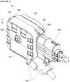
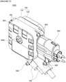
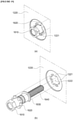
- FIG. 1 is a perspective view of a fuse connector that is an example of a fuse-integrated electronic component according to a first embodiment of the present invention
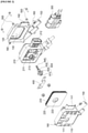
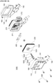
- FIG. 2 is an exploded perspective view of FIG. 1
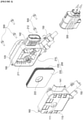
- FIG. 3 is a perspective view illustrating a state in which a first housing and an inner cover are separated from each other in FIG. 1
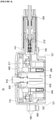
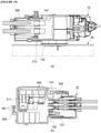
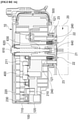
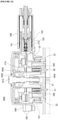
- FIG. 4 is a cross-sectional view taken along line IV-IV of FIG. 1
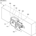
- FIG. 5 is a perspective view illustrating a state in which the fuse connector of FIG. 1 is installed in a power supply part
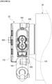
- FIG. 6 is one side view of FIG. 5
- FIG. 7 is a view illustrating a state when a first coupling member is released in FIG. 6 .
- FIG. 1 is a perspective view of a fuse connector that is an example of a fuse-integrated electronic component according to a first embodiment of the present invention
- FIG. 2 is an exploded perspective view of FIG. 1
- FIG. 3 is a perspective view illustrating a state in which a
- FIG. 8 is a schematic circuit diagram illustrating an example of FIG. 5
- FIG. 9 is a schematic circuit diagram illustrating another example of FIG. 5
- FIG. 10(a) to 10(c) are views illustrating a process of replacing a fuse of the fuse connector of FIG. 5 .
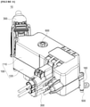
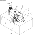
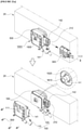
- FIG. 11 is a perspective view illustrating a junction block that is another example of the fuse-integrated electronic component according to the first embodiment of the present invention
- FIG. 12 is an exploded perspective view of FIG. 11
- FIG. 13 is a perspective view illustrating a state in which the first housing and the inner cover are separated from each other in FIG. 11
- FIG. 14 is a perspective view illustrating a state in which the junction connector of FIG. 11 is installed in the power supply part
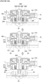
- FIG. 15 is a cross-sectional view taken in a direction XV-XV of FIG. 14
- FIG. 16 is a cross-sectional view taken in a direction XVI-XVI of FIG. 14 .
- a fuse-integrated electronic component 10 includes an outer housing 100 which is fixed by a first coupling member 500 in a state in which first and second housings 110 and 120 are engaged with each other to define an accommodation space 130 and in which an extension part 140 is disposed at one side thereof, an inner body 210 installed in the accommodation space 130 by a second coupling member 600 to define a mounting space 211, a connector 300 connected to the outer housing 100 so that the extension part 140 is accommodated inside the connector 300 to supply power to the fuse-integrated electronic component 10, and a fuse 400 installed in the mounting space 211 to cut off a high voltage output to the connector 300.
- the fuse-integrated electronic component 10 is connected to a power supply part 20.
- the first coupling member 500 is disposed to be coupled and released between the outer housing 100 and the power supply part 20 so that the first coupling member 500 is released in a state of being separated from the power supply part 20.
- the fuse-integrated electronic component 10 may be a component through which a high voltage is input and output to supply or transmit electricity to another device or other components among components used in electric devices of a vehicle.
- an installation of a fuse 400 is required for safety.
- the fuse connector, the junction block, etc. correspond to the fuse-integrated electronic component 10
- the power supply part 20 corresponds to a battery, an inverter, etc. electrically connected thereto.
- the outer housing 100 is constituted by the first and second housings 110 and 120 that are engage with each other to define the accommodation space 130 therein, and the extension part 140 is disposed at one side so that the connector 300 is connected to one side of the inner body 210.
- the first housing 110 is disposed outside the inner cover 220
- the second housing 120 is disposed outside the inner body 210 so that the inner housing 200 is accommodated in the internal communication space 130 defined between the first housing 110 and the second housing 120.
- a first extension part 141 is disposed at one side of the first housing 110
- a second extension part 142 is disposed at one side of the second housing 120 so that the first and second housings 110 and 120 are engaged with each other, as a result, the first and second extension parts 141 and 142 are disposed to surround the outside of a connector connection part 212.
- the first and second extension parts 141 and 142 are accommodated into the connector 300 electrically connected to the connector connection part 212.
- the release of the connector 300 has to proceed in advance to separate the first and second housings 110 and 120 from each other, and then, a relay inside the power supply part 20 is turned off to cut off the high voltage.
- a work hole 111 is defined in the first housing 110 to correspond to a position of a through-hole 213 to expose a work head 610 of the second coupling member 600 to the outside of the outer housing 100, thereby improving workability.
- the second housing 120 has both sides that are opened in a coupling/releasing direction of the second coupling member 600 so that a first terminal 22 disposed at one side of the power supply part 20 and a second terminal 240 embedded inside the inner body 210 are electrically connected to each other.
- a hook protrusion 121 that is hooked on a hook rib disposed to protrude from the power supply part 20 so as to restrict an insertion of the fuse-integrated electronic component 10 is disposed at one side of the second housing 120 to prevent the first and second terminals 22 and 240 from being excessively inserted, thereby protecting the terminals and improving product reliability.
- a cable connection part 150 in which a wire that outputs power to the outside is accommodated is provided to surround a cable when the first and second housings 110 and 120 are coupled to each other, thereby protecting the connected portions, and a first coupling hole 160 to which the first coupling member 500 is coupled is provided in plurality along a circumference of each of the first and second housings 110 and 120.
- the first coupling hole is opened in a coupling/releasing direction of the first coupling member 500 so that the first coupling member 500 is coupled in any direction.
- the separation of the power supply part 20 and the fuse-integrated electronic component 10 has to be essentially performed in advance to separate the outer housing 100 so that the first coupling member 500 is coupled and released between the second housing 120 and the power supply part 20.
- the first and second housings 110 and 120 have a shape, in which the first and second housings 110 and 120 are engaged with each other to define the accommodation space 130 for accommodating the inner housing 200.
- the first coupling member 500 is coupled to the first coupling hole 160 to prevent the outer housing 100 from being separated without releasing the first coupling member 500, and the first coupling member 500 is inserted from the outside of the second housing 120 so that the fuse-integrated electronic component 10 and the power supply part 20 have to be essentially separated to separate the outer housing 100.
- the processes of releasing the connector 300 to be separated from the power supply part 20 has to essentially performed in advance so as to replace the fuse 400 installed in the mounting space 211.
- the connector 300 is separated, and the first and second terminals 22 and 240 are separated from each other before replacing the fuse 400 to cut off the high voltage doubly, thereby significantly improving stability of the worker.
- the inner housing 200 is provided with an inner body 210 accommodated in the accommodation space 130 and an inner cover 220 coupled to one side of the inner body 210 to protect components electrically connected to each other such as the fuse 400, a bus bar, the cable, and the like, which are installed in the mounting space 211 defined in the inner body 210.
- the inner body 210 defines the mounting space 211 in which the components are installed, and the connector connection part 212 connected to the connector 300 is disposed at one side of the inner body 210. Also, the through-hole 213, through which the second coupling member 600 passes, and a coupling space 214, in which a coupling part 21 of the power supply part 20 is disposed to one side of the through-hole 213, are defined in the inner body 210. In addition, the second terminal 230 electrically connected to the first terminal 22 to correspond to the position of the first terminal 22 are embedded in the inner body 210.
- the inner cover 220 is coupled to the inner body 210 to cover an opening of the mounting space 211, thereby protecting the components installed therein, and a communication hole 222 through which the work hole 111 and the through-hole 213 communicate with each other is defined in the inner cover 220 so that the second coupling member 600 is fixed to the coupling part 21.
- a packing 230 is disposed between the inner body 210 and the inner cover 220 to prevent moisture, impurities, etc. from being introduced into the mounting space 211.
- the components for the electrical connection are protected doubly by the inner housing 200 and the outer housing 100 to improve durability of the product, and also, the inner body 210, in which the mounting space 211, in which the components are substantially installed, is defined, is formed to enable a complex structure to be more easily formed through injection.
- the packing 230 is provided to offset an injection tolerance, and a hook protrusion 121 that is in contact with the hook rib 23 of the power supply part 20 to limit a degree of insertion of each of the fuse-integrated electronic component 10 and the power supply part 20 is disposed on the outer housing 100 so that the first and second terminals 22 and 240 are electrically connected to each other at a predetermined position to improve the reliability of the product.
- the connector 300 is connected to the connector connection part 212 so as to be electrically connected to an external device and is provided in various types. Also, an interlock terminal is provided in the connector 300, and thus, when the interlock terminal is released from the connector connection part 212, a circuit electrically connected to the interlock terminal is electrically cut off to allow the relay provided in the power supply part 20 to be turned off.
- the connector 300 accommodates the extension part 140 disposed in the outer housing 100 therein and is connected to the connector connection part 212.
- the connector 300 has to be essentially released from the connector connection part 212, and thus, the interlock terminal is separated to turn off the relay disposed in the power supply part 20 so as to cut off the high voltage.
- the fuse-integrated electronic component 10 is provided with the interlock terminal inside the connector 300 so that the high voltage is cut off through the turn-off of the relay just by separating the connector 300, thereby realizing more stable work.
- the second coupling member 600 includes a work head 610, a close contact end 620 disposed at one side of the through-hole 213, a body ascending end 630 disposed at the other side of the through-hole 213, and a screw part 640 that is screw-coupled to the coupling part 21 disposed in the power supply part 20 by passing through the through-hole 213, and thus, the second coupling member 600 is hooked to be fixed to the inner body 210 regardless of the coupling or releasing to/from the power supply part 20.
- a distance between the close contact end 620 and the body ascending end 630 is longer than a length of the through-hole 213 and is hooked to be fixed to the inner body 210, thereby fundamentally preventing the second coupling member 600 from being lost in the working process.
- the second coupling member 600 is provided to be movable by a predetermined distance in the coupling direction so that the second coupling member 600 is easily located at the coupling part 21 by the worker to improve the workability.
- a power supply part 20 has to be separated for replacing the fuse 400 installed in a mounting space 211 in a state in which a high voltage is input or output in a state in which first and second terminals 22 and 240 are connected to each other.
- a connector 300 has to also be separated in a state in which the connector 300 is connected to a connector connection part 212, but an order in which the power supply part 20 and the connector 300 are separated is not limited. However, for convenience of description, the following description will be described based on the connector 300 being separated in advance.
- the connector 300 connected to the connector connection part 212 is separated, and thus, an internal interlock terminal of the connector 300 is electrically cut off a relay of the power supply part 20. Therefore, the relay is in an OFF state, a high voltage is first cut off, and an extension part 140 accommodated in the connector 300 is also in a separable state.
- a first coupling member 500 is coupled from the outside of a second housing 120 in a direction of the first housing 110 to prevent an outer housing 100 from being separated from first and second housings 110 and 120 when not separated from the power supply part 20.
- a worker releases a second coupling member 600 in advance.
- the body ascending end 630 is disposed at a first position P1 at which a body ascending end 630 is spaced a first distance D1 from a through-hole 213 in a state in which the second coupling member 600 is completely coupled to the coupling part 21, and the worker rotates a work head 610 through a tool to allow a screw part 640 to be released from the coupling part 21.
- the second coupling member 600 moves to the outside of the first housing 110, and then, when the second coupling member 600 moves by a first distance D1, a body ascending end 630 is disposed at a second position P2 that is in contact with one side of a through-hole 213.
- the second coupling member 600 moves to ascend together with an inner body 210, and thus, the second coupling member 600 is fundamentally released so that the first and second terminals 22 and 240 are separated together from each other.
- a distance in a linear direction to which the screw part 640 of the second coupling member 600 moves so as to be completely separated from the coupling part 21 of the power supply part 20 is equal to or greater than a distance at which the first and second terminals 22 and 240 are coupled to each other.
- the first and second terminals may have a coupling distance less than the linear distance of the screw coupling in which the screw part 640 and the coupling part 21 are coupled to each other.
- the fuse-integrated electronic component 10 is also separated from the power supply part 20 to improve workability, and the first coupling member 500 is also exposed so that the worker conveniently release the first coupling member 500 from a first coupling hole 160.
- the worker separates the first housing 110 and the inner cover 220 from each other to more safely replace the electrically connected components such as a fuse 400 installed in a mounting space 211.
- the fuse connector corresponding to an example of the first embodiment of the present invention has a fuse 400 installed therein.
- a fuse 400 inside a battery which corresponds to a power supply source, may be excluded to significantly improve workability during the replacement, thereby significantly reducing maintenance cost and man-hours.
- the fuse-integrated electronic component 10 discloses a new structure that doubly cuts off the high voltage to replace the fuse 400 to significantly improve the stability and workability of the worker.
- the fuse 400 is installed in the fuse connector to significantly reduce the number of man-hours for the typical releasing operation, thereby maximizing the effect of improving the workability.
- fuse-integrated electronic component 1000 according to a second embodiment will be described.
- the fuse-integrated electronic component 10 according to the first embodiment and the fuse-integrated electronic component 1000 according to the second embodiment have the same technical solution and have the same purpose and function, description of the same configuration will be omitted.
- FIG. 17 is a perspective view of a fuse connector that is an example of a fuse-integrated electronic component according to a second embodiment of the present invention
- FIG. 18 is an exploded perspective view of FIG. 17
- FIG. 19 is a view illustrating a shape depending on positions of a communication hole and a close contact end of FIG. 17
- FIG. 20 is a perspective view illustrating a state in which the fuse connector of FIG. 17 is installed in a power supply part
- FIG. 21 is a cross-sectional view taken in a direction XX-XX of FIG. 20
- FIG. 22(a) to 22(c) are views illustrating a process of replacing a fuse of the fuse connector of FIG. 20 .
- a fuse-integrated electronic component 1000 includes an outer housing 100 which is fixed by a first coupling member 500 in a state in which first and second housings 110 and 120 are engaged with each other to define an accommodation space 130 and in which an extension part 140 is disposed at one side thereof, an inner body 210 installed in the accommodation space 130 to define a mounting space 211, an inner cover 1220 that is in close contact with one side of the inner body 210 to cover the mounting space 211, a second coupling member 1600 passing through a communication hole 1222 defined in the inner body 210 and a through-hole 213 defined in the inner cover 1220 at the same time, a connector 300 connected to the outer housing 100 so that the extension part 140 is accommodated inside the connector 300 to supply power to the fuse-integrated electronic component 10, and a fuse 400 installed in the mounting space 211 to cut off a high voltage output to the connector 300.
- the second coupling member 1600 includes a work head 1610 exposed to the outside of the outer housing 100 so as to be engaged with a tool, a close contact end 1620 hooked on an outer surface of the inner cover 1220 to prevent the inner cover 1220 from being separated, a body ascending end 1630 hooked on one side of the through-hole 213, and a screw part 1640 having a screw thread to be coupled to a coupling part 21 disposed in a power supply part 20, and the communication hole 222 and the close contact end 1620 have the same shape and are disposed to correspond to predetermined positions by rotation of the second coupling member 1600.
- the fuse-integrated electronic component 1000 according to the second embodiment of the present invention discloses a structure different from that according to the first embodiment so that the fuse 400 is removed, and simultaneously, the first coupling member 500 is coupled in a direction of a second housing 120 at the outside of the first housing 110.
- the inner cover 1220 of the fuse-integrated electronic component 1000 includes an extension end 1221 inside the communication hole 1222, and the close contact end 1620 of the second coupling member 1600 is disposed outside the inner cover 1220 to prevent the inner cover 1220 from being separated in a state in which the second coupling member 1600 is coupled to a coupling part 21.
- the extension end 1221 of the inner cover 1220 extends to have a specific shape along an inner circumferential surface of the communication hole 1222, and the close contact end 1620 of the second coupling member 1600 also has the same shape as the communication hole 1222 by the extension end 1221.
- the communication hole 1222 and the close contact end 1620 are disposed to correspond to each other only at predetermined positions so as to prevent the inner cover 1220 from being arbitrarily separated while the second coupling member 1600 is released, thereby securing safety.
- the shapes of the communication hole 1222 and the close contact end 1620 of the second coupling member 1600 by the extension end 1221 of the inner cover 1220 have a shape in which an uneven shape is repeated along a circumference as illustrated in FIG. 19 .
- the close contact end 1620 and one surface of the extension end 1221 are in contact with each other to prevent the inner cover 1220 from being separated.
- the inner cover may be separated at a position at which the two shapes overlap each other.
- the extension end 1221 may be provided as one protrusion or hole
- the close contact end 1620 may be provided as one hole or protrusion, which has a shape corresponding to the one protrusion or hole so that the inner cover 1220 is separated at only a specific position, which is capable of being variously changed by changing the design as needed.
- the fuse-integrated electronic component 1000 according to the second embodiment of the present invention is not limited by the coupling direction of the first coupling member 500, and thus provides improved usability in relation to surrounding components.
- a power supply part 20 has to be separated for replacing the fuse 400 installed in a mounting space 211 in a state in which a high voltage is input or output in a state in which first and second terminals 22 and 240 are connected to each other.
- a connector 300 has to also be separated in a state in which the connector 300 is connected to a connector connection part 212, but an order in which the power supply part 20 and the connector 300 are separated is not limited. However, for convenience of description, the following description will be described based on the connector 300 being separated in advance.
- the connector 300 connected to the connector connection part 212 is separated, and thus, an internal interlock terminal of the connector 300 is electrically cut off a relay of the power supply part 20. Therefore, the relay is in an OFF state, a high voltage is first cut off, and an extension part 140 accommodated in the connector 300 is also in a separable state.
- the first coupling member 500 may be removed in the state of being coupled to the power supply part 20 so that the first housing 110 is separated.
- the inner cover 1220 may not be separated by the second coupling member 1600, and thus, the second coupling member 1600 has to be released in advance to replace the fuse 400 installed in the mounting space 211.
- a worker releases a second coupling member 1600 first.
- the body ascending end 1630 is disposed at a first position P1 at which a body ascending end 630 is spaced a first distance D1 from a through-hole 213 in a state in which the second coupling member 600 is completely coupled to the coupling part 21, and the worker rotates a work head 1610 through a tool to allow a screw part 1640 to be released from the coupling part 21.
- the second coupling member 1600 moves to the outside of the first housing 110, and then, when the second coupling member 1600 moves by a first distance D1, a body ascending end 1630 is disposed at a second position P2 that is in contact with one side of a through-hole 213.
- the second coupling member 1600 moves to ascend together with an inner body 1210, and thus, the second coupling member 1600 is fundamentally released so that the first and second terminals 22 and 240 are separated together from each other.
- the first and second terminals 22 and 240 may have a coupling distance less than the linear distance of the screw coupling in which the screw part 1640 and the coupling part 21 are coupled to each other.
- the second coupling member 1600 when the second coupling member 1600 is completely released from the coupling part 21, it is hooked to be fixed to the inner body 210 by the close contact end 1620 and the body ascending end 1630. However, since it is freely rotatable, the worker rotates the second coupling member 1600 to adjust the communication hole 222 and the close contact end 1620 so as to match each other, and then, the inner cover 1220 is separated from the inner body 210 to replace the fuse 400.
- the fuse-integrated electronic component 1000 improves a degree of freedom of a design regardless of the coupling direction of the first coupling member 500, and when replacing components such as the fuse 400 installed therein, the high voltage is primarily cut off through a relay and secondarily block the direction connection by separating the first and second terminals 22 and 240 from each other, thereby enabling the safer work.
- the fuse-integrated electronic components 10 and 1000 according to the present invention disclose the coupling structure that is capable of doubly cutting off the high voltage when replacing the components such as the internal fuse 400 so that the worker performs the replacement work more safely, and the workability is improved to reduce maintenance costs.
- the extension parts that are engaged with each other may be provided at one side of the first and second housings defining the outer housing, and also, the extension parts may be accommodated into the connector, and thus, the high voltage connector has to be removed for replacing the fuse installed inside the connector so as to ensure the stability.
- the fuse-integrated electronic component may have the structure capable of being applied to the junction block connected to the inverter and the structure capable of being applied by directly installing the fuse in the connector connected to the battery. Therefore, the versatility of the fuse-integrated electronic component may be very high, and the workability of replacing the fuse may be improved.
- the second coupling member may be provided with the close contact end and the body ascending end so as to be hooked and fixed to the inner body so that the second coupling member is prevented from being lost when the outer housing and the inner cover are separated from each other to disassemble the fuse, and simultaneously, allows the inner housing to ascend so that the first and second terminals are separated from each other to cut off the power doubly, thereby significantly improving the stability of the worker.
- the first coupling member of the fuse-integrated electronic component according to the first embodiment may be disposed to be coupled and released between the outer housing and the power supply part so that the first and second terminals are essentially separated from each other to disassemble the outer housing, thereby maximizing the effect of improving the stability.
- the second coupling member may be hooked and fixed to the inner body so as not to be restricted in the direction in which the first coupling member is coupled and released, and simultaneously, to fix the inner cover to induce the proceeding separation of the first and second terminals, thereby maintaining the effect of improving the stability.
Abstract
Description
- The present invention relates to a fuse-integrated electronic component, and more particularly, to a fuse-integrated electronic component used in electric devices of vehicles.
- In general, many electric devices are installed in a vehicle, and the electric devices are electrically connected to other electric devices or power sources through cables and connectors connected thereto.
- Thus, a high voltage battery is installed in the vehicle to supply power to a number of electric devices, and an interlock terminal that is designed in the battery and is capable of turning off a fuse and a relay installed in the battery to cut off an abnormal high voltage when the abnormal high voltage occurs is provided for the safety of workers or passengers.
- However, in the related art, the battery has to be disassembled to replace the fuse, thereby significantly deteriorating workability, and if the relay is fused, the high voltage is not cut off even when the interlock terminal is disconnected, thereby significantly deteriorating safety.
- To solve the above-mentioned limitations, the present invention provides a fuse-integrated electronic component, which significantly improves safety and workability of a worker by cutting off power when replacing a fuse.
- In accordance with an embodiment of the present invention, a fuse-integrated electronic component, which is connected to a power supply part, includes: an outer housing which is fixed by a first coupling member in a state in which first and second housings are engaged with each other to define an accommodation space and in which an extension part is disposed at one side thereof; an inner body installed in the accommodation space by a second coupling member to define a mounting space; a connector connected to the outer housing so that the extension part is accommodated therein; and a fuse installed in the mounting space to cut off a high voltage output to the connector, wherein the first coupling member is disposed to be coupled and released between the outer housing and the power supply part so that the first coupling member is released in a state of being separated from the power supply part.
- The inner body may be provided with a second terminal electrically connected to the first terminal provided in the power supply part, and in a state of being separated from the power supply part, the first and second terminals may also be separated from each other to cut off the supply of the power.
- The second coupling member may be coupled to a coupling part provided in the power supply part by passing through a through-hole of the inner body, wherein a body ascending end hooked on the inner body may be provided to be released so that the first and second terminals are separated together from each other.
- The body ascending end may be disposed at a first position spaced apart from the through-hole in a state of being completely coupled to the coupling part and be disposed at a second position that is in contact with one side of the through-hole when the second coupling member is released to move by a first distance so as to move together with the inner body until the second coupling member is completely released, thereby separating the first and second terminals from each other.
- The connector may be provided with an interlock terminal electrically connected to a relay installed inside the power supply part.
- In accordance with another embodiment of the present invention, a fuse-integrated electronic component, which is connected to a power supply part, includes: an outer housing which is fixed by a first coupling member in a state in which first and second housings are engaged with each other to define an accommodation space and in which an extension part is disposed at one side thereof; an inner body installed in the accommodation space to define a mounting space; an inner cover that is in close contact with one side of the inner body to cover the mounting space; a second coupling member passing through a communication hole defined in the inner body and a through-hole defined in the inner cover at the same time; a connector connected to the outer housing so that the extension part is accommodated therein; and a fuse installed in the mounting space to cut off a high voltage output to the connector, wherein the second coupling member comprises a work head exposed to the outside of the outer housing so as to be engaged with a tool, a close contact end hooked on an outer surface of the inner cover to prevent the inner cover from being separated, a body ascending end hooked on one side of the through-hole, and a screw part having a screw thread to be coupled to a coupling part disposed in a power supply part, wherein the communication hole and the close contact end have the same shape and are disposed to correspond to predetermined positions by rotation of the second coupling member.
- The inner body may be provided with a second terminal electrically connected to the first terminal provided in the power supply part, and as the first coupling part is released, the inner body may ascend together by the body ascending end so that, in a state in which the fuse-integrated electronic component is separated from the power supply part, the first and second terminals are also separated from each other to cut off the supply of the power.
- The body ascending end may be disposed at a first position spaced apart from the through-hole in a state of being completely coupled to the coupling part and be disposed at a second position that is in contact with one side of the through-hole when the second coupling member is released to move by a first distance so as to move together with the inner body until the second coupling member is completely released, thereby separating the first and second terminals from each other.
- The connector may be provided with an interlock terminal electrically connected to a relay installed inside the power supply part.
- The accompanying drawings are included to provide a further understanding of the present invention, and are incorporated in and constitute a part of this specification. The drawings illustrate exemplary embodiments of the present invention and, together with the description, serve to explain principles of the present invention. In the drawings:
-
FIG. 1 is a perspective view of a fuse connector that is an example of a fuse-integrated electronic component according to a first embodiment of the present invention; -
FIG. 2 is an exploded perspective view ofFIG. 1 ; -
FIG. 3 is a perspective view illustrating a state in which a first housing and an inner cover are separated from each other inFIG. 1 ; -
FIG. 4 is a cross-sectional view taken along line IV-IV ofFIG. 1 ; -
FIG. 5 is a perspective view illustrating a state in which the fuse connector ofFIG. 1 is installed in a power supply part; -
FIG. 6 is one side view ofFIG. 5 ; -
FIG. 7 is a view illustrating a state when a first coupling member is released inFIG. 6 ; -
FIG. 8 is a schematic circuit diagram illustrating an example ofFIG. 5 ; -
FIG. 9 is a schematic circuit diagram illustrating another example ofFIG. 5 ; -
FIG. 10(a) to 10(c) are views illustrating a process of replacing a fuse of the fuse connector ofFIG. 5 ; -
FIG. 11 is a perspective view illustrating a junction block that is another example of the fuse-integrated electronic component according to the first embodiment of the present invention; -
FIG. 12 is an exploded perspective view ofFIG. 11 ; -
FIG. 13 is a perspective view illustrating a state in which the first housing and the inner cover are separated from each other inFIG. 11 ; -
FIG. 14 is a perspective view illustrating a state in which the junction connector ofFIG. 11 is installed in the power supply part; -
FIG. 15 is a cross-sectional view taken in a direction XV-XV ofFIG. 14 ; -
FIG. 16 is a cross-sectional view taken in a direction XVI-XVI ofFIG. 14 ; -
FIG. 17 is a perspective view of a fuse connector that is an example of a fuse-integrated electronic component according to a second embodiment of the present invention; -
FIG. 18 is an exploded perspective view ofFIG. 17 ; -
FIG. 19 is a view illustrating a shape depending on positions of a communication hole and a close contact end ofFIG. 17 ; -
FIG. 20 is a perspective view illustrating a state in which the fuse connector ofFIG. 17 is installed in a power supply part; -
FIG. 21 is a cross-sectional view taken in a direction XX-XX ofFIG. 20 ; and -
FIG. 22(a) to 22(c) are views illustrating a process of replacing a fuse of the fuse connector ofFIG. 20 . - Hereinafter, specific embodiments of the present invention will be described in detail with reference to the drawings. However, in order not to obscure the gist of the present invention, detailed descriptions of well-known functions or configurations will be omitted.
- In addition, for convenience of description of the invention, although the same reference numerals are given to a fuse connector corresponding to a fuse-integrated electronic component according to a first embodiment and a junction block, and the same reference numerals are given to a fuse connector corresponding to a fuse-integrated electronic component according to a second embodiment, only the best reference numeral may be changed and given to different components.
-
FIG. 1 is a perspective view of a fuse connector that is an example of a fuse-integrated electronic component according to a first embodiment of the present invention,FIG. 2 is an exploded perspective view ofFIG. 1 ,FIG. 3 is a perspective view illustrating a state in which a first housing and an inner cover are separated from each other inFIG. 1 ,FIG. 4 is a cross-sectional view taken along line IV-IV ofFIG. 1 ,FIG. 5 is a perspective view illustrating a state in which the fuse connector ofFIG. 1 is installed in a power supply part,FIG. 6 is one side view ofFIG. 5 , andFIG. 7 is a view illustrating a state when a first coupling member is released inFIG. 6 .FIG. 8 is a schematic circuit diagram illustrating an example ofFIG. 5 , andFIG. 9 is a schematic circuit diagram illustrating another example ofFIG. 5 .FIG. 10(a) to 10(c) are views illustrating a process of replacing a fuse of the fuse connector ofFIG. 5 . -
FIG. 11 is a perspective view illustrating a junction block that is another example of the fuse-integrated electronic component according to the first embodiment of the present invention,FIG. 12 is an exploded perspective view ofFIG. 11 ,FIG. 13 is a perspective view illustrating a state in which the first housing and the inner cover are separated from each other inFIG. 11 ,FIG. 14 is a perspective view illustrating a state in which the junction connector ofFIG. 11 is installed in the power supply part,FIG. 15 is a cross-sectional view taken in a direction XV-XV ofFIG. 14 , andFIG. 16 is a cross-sectional view taken in a direction XVI-XVI ofFIG. 14 . - Referring to
FIGS. 1 to 16 , a fuse-integratedelectronic component 10 according to a first embodiment of the present invention includes anouter housing 100 which is fixed by afirst coupling member 500 in a state in which first andsecond housings accommodation space 130 and in which anextension part 140 is disposed at one side thereof, aninner body 210 installed in theaccommodation space 130 by asecond coupling member 600 to define amounting space 211, aconnector 300 connected to theouter housing 100 so that theextension part 140 is accommodated inside theconnector 300 to supply power to the fuse-integratedelectronic component 10, and afuse 400 installed in themounting space 211 to cut off a high voltage output to theconnector 300. The fuse-integratedelectronic component 10 is connected to apower supply part 20. Thefirst coupling member 500 is disposed to be coupled and released between theouter housing 100 and thepower supply part 20 so that thefirst coupling member 500 is released in a state of being separated from thepower supply part 20. - Here, the fuse-integrated
electronic component 10 may be a component through which a high voltage is input and output to supply or transmit electricity to another device or other components among components used in electric devices of a vehicle. Here, an installation of afuse 400 is required for safety. - As an example, as illustrated in the drawings, the fuse connector, the junction block, etc. correspond to the fuse-integrated
electronic component 10, and thus, thepower supply part 20 corresponds to a battery, an inverter, etc. electrically connected thereto. - The
outer housing 100 is constituted by the first andsecond housings accommodation space 130 therein, and theextension part 140 is disposed at one side so that theconnector 300 is connected to one side of theinner body 210. - Particularly, the
first housing 110 is disposed outside theinner cover 220, and thesecond housing 120 is disposed outside theinner body 210 so that theinner housing 200 is accommodated in theinternal communication space 130 defined between thefirst housing 110 and thesecond housing 120. Also, afirst extension part 141 is disposed at one side of thefirst housing 110, and asecond extension part 142 is disposed at one side of thesecond housing 120 so that the first andsecond housings second extension parts connector connection part 212. - Thereafter, the first and
second extension parts connector 300 electrically connected to theconnector connection part 212. Here, the release of theconnector 300 has to proceed in advance to separate the first andsecond housings power supply part 20 is turned off to cut off the high voltage. - In addition, a
work hole 111 is defined in thefirst housing 110 to correspond to a position of a through-hole 213 to expose awork head 610 of thesecond coupling member 600 to the outside of theouter housing 100, thereby improving workability. Thesecond housing 120 has both sides that are opened in a coupling/releasing direction of thesecond coupling member 600 so that afirst terminal 22 disposed at one side of thepower supply part 20 and asecond terminal 240 embedded inside theinner body 210 are electrically connected to each other. - However, a
hook protrusion 121 that is hooked on a hook rib disposed to protrude from thepower supply part 20 so as to restrict an insertion of the fuse-integratedelectronic component 10 is disposed at one side of thesecond housing 120 to prevent the first andsecond terminals - In addition, in the first and
second housings cable connection part 150 in which a wire that outputs power to the outside is accommodated is provided to surround a cable when the first andsecond housings first coupling hole 160 to which thefirst coupling member 500 is coupled is provided in plurality along a circumference of each of the first andsecond housings - Here, the first coupling hole is opened in a coupling/releasing direction of the
first coupling member 500 so that thefirst coupling member 500 is coupled in any direction. In the fuse-integratedelectronic component 10 according to the first embodiment of the present invention, the separation of thepower supply part 20 and the fuse-integratedelectronic component 10 has to be essentially performed in advance to separate theouter housing 100 so that thefirst coupling member 500 is coupled and released between thesecond housing 120 and thepower supply part 20. - In summary, the first and
second housings second housings accommodation space 130 for accommodating theinner housing 200. Thefirst coupling member 500 is coupled to thefirst coupling hole 160 to prevent theouter housing 100 from being separated without releasing thefirst coupling member 500, and thefirst coupling member 500 is inserted from the outside of thesecond housing 120 so that the fuse-integratedelectronic component 10 and thepower supply part 20 have to be essentially separated to separate theouter housing 100. - Therefore, in the fuse-integrated
electronic component 10 according to the first embodiment of the present invention, the processes of releasing theconnector 300 to be separated from thepower supply part 20 has to essentially performed in advance so as to replace thefuse 400 installed in the mountingspace 211. Thus, in the fuse-integratedelectronic component 10 according to the present invention, theconnector 300 is separated, and the first andsecond terminals fuse 400 to cut off the high voltage doubly, thereby significantly improving stability of the worker. - The
inner housing 200 is provided with aninner body 210 accommodated in theaccommodation space 130 and aninner cover 220 coupled to one side of theinner body 210 to protect components electrically connected to each other such as thefuse 400, a bus bar, the cable, and the like, which are installed in the mountingspace 211 defined in theinner body 210. - The
inner body 210 defines the mountingspace 211 in which the components are installed, and theconnector connection part 212 connected to theconnector 300 is disposed at one side of theinner body 210. Also, the through-hole 213, through which thesecond coupling member 600 passes, and acoupling space 214, in which acoupling part 21 of thepower supply part 20 is disposed to one side of the through-hole 213, are defined in theinner body 210. In addition, thesecond terminal 230 electrically connected to thefirst terminal 22 to correspond to the position of thefirst terminal 22 are embedded in theinner body 210. - The
inner cover 220 is coupled to theinner body 210 to cover an opening of the mountingspace 211, thereby protecting the components installed therein, and acommunication hole 222 through which thework hole 111 and the through-hole 213 communicate with each other is defined in theinner cover 220 so that thesecond coupling member 600 is fixed to thecoupling part 21. - Here, a packing 230 is disposed between the
inner body 210 and theinner cover 220 to prevent moisture, impurities, etc. from being introduced into the mountingspace 211. - In other words, in the fuse-integrated
electronic component 10 according to the present invention, the components for the electrical connection are protected doubly by theinner housing 200 and theouter housing 100 to improve durability of the product, and also, theinner body 210, in which the mountingspace 211, in which the components are substantially installed, is defined, is formed to enable a complex structure to be more easily formed through injection. - Here, the packing 230 is provided to offset an injection tolerance, and a
hook protrusion 121 that is in contact with thehook rib 23 of thepower supply part 20 to limit a degree of insertion of each of the fuse-integratedelectronic component 10 and thepower supply part 20 is disposed on theouter housing 100 so that the first andsecond terminals - The
connector 300 is connected to theconnector connection part 212 so as to be electrically connected to an external device and is provided in various types. Also, an interlock terminal is provided in theconnector 300, and thus, when the interlock terminal is released from theconnector connection part 212, a circuit electrically connected to the interlock terminal is electrically cut off to allow the relay provided in thepower supply part 20 to be turned off. - In addition, the
connector 300 accommodates theextension part 140 disposed in theouter housing 100 therein and is connected to theconnector connection part 212. As a result, to separate theouter housing 100, theconnector 300 has to be essentially released from theconnector connection part 212, and thus, the interlock terminal is separated to turn off the relay disposed in thepower supply part 20 so as to cut off the high voltage. - Therefore, the fuse-integrated
electronic component 10 according to the present invention is provided with the interlock terminal inside theconnector 300 so that the high voltage is cut off through the turn-off of the relay just by separating theconnector 300, thereby realizing more stable work. - The
second coupling member 600 includes awork head 610, aclose contact end 620 disposed at one side of the through-hole 213, abody ascending end 630 disposed at the other side of the through-hole 213, and ascrew part 640 that is screw-coupled to thecoupling part 21 disposed in thepower supply part 20 by passing through the through-hole 213, and thus, thesecond coupling member 600 is hooked to be fixed to theinner body 210 regardless of the coupling or releasing to/from thepower supply part 20. - Here, a distance between the
close contact end 620 and thebody ascending end 630 is longer than a length of the through-hole 213 and is hooked to be fixed to theinner body 210, thereby fundamentally preventing thesecond coupling member 600 from being lost in the working process. Also, thesecond coupling member 600 is provided to be movable by a predetermined distance in the coupling direction so that thesecond coupling member 600 is easily located at thecoupling part 21 by the worker to improve the workability. - Hereinafter, a method of disassembling the
fuse 400 to replace afuse 400 in a state in which the fuse-integratedelectronic component 10 according to the first embodiment of the present invention is coupled to thepower supply part 20 will be described in detail. - In the fuse-integrated
electronic component 10 according to the first embodiment of the present invention, apower supply part 20 has to be separated for replacing thefuse 400 installed in a mountingspace 211 in a state in which a high voltage is input or output in a state in which first andsecond terminals - Here, in the fuse-integrated
electronic component 10, aconnector 300 has to also be separated in a state in which theconnector 300 is connected to aconnector connection part 212, but an order in which thepower supply part 20 and theconnector 300 are separated is not limited. However, for convenience of description, the following description will be described based on theconnector 300 being separated in advance. - To replace the
fuse 400, theconnector 300 connected to theconnector connection part 212 is separated, and thus, an internal interlock terminal of theconnector 300 is electrically cut off a relay of thepower supply part 20. Therefore, the relay is in an OFF state, a high voltage is first cut off, and anextension part 140 accommodated in theconnector 300 is also in a separable state. - Thereafter, it is common to remove a
first housing 110 and aninner cover 220 so as to replace thefuse 400 therein, but when the relay is fused, the high voltage is not cut off simply by separating the interlock terminal. As a result, there is a limitation that safety of the work is significantly deteriorated because additional accidents occurs. - Therefore, in the fuse-integrated
electronic component 10 according to the first embodiment of the present invention, afirst coupling member 500 is coupled from the outside of asecond housing 120 in a direction of thefirst housing 110 to prevent anouter housing 100 from being separated from first andsecond housings power supply part 20. - Thus, a worker releases a
second coupling member 600 in advance. Particularly, in thesecond coupling member 600, thebody ascending end 630 is disposed at a first position P1 at which abody ascending end 630 is spaced a first distance D1 from a through-hole 213 in a state in which thesecond coupling member 600 is completely coupled to thecoupling part 21, and the worker rotates awork head 610 through a tool to allow ascrew part 640 to be released from thecoupling part 21. - Here, as the
screw part 640 is released from thecoupling part 21, thesecond coupling member 600 moves to the outside of thefirst housing 110, and then, when thesecond coupling member 600 moves by a first distance D1, abody ascending end 630 is disposed at a second position P2 that is in contact with one side of a through-hole 213. As a result, thesecond coupling member 600 moves to ascend together with aninner body 210, and thus, thesecond coupling member 600 is fundamentally released so that the first andsecond terminals - In other words, a distance in a linear direction to which the
screw part 640 of thesecond coupling member 600 moves so as to be completely separated from thecoupling part 21 of thepower supply part 20 is equal to or greater than a distance at which the first andsecond terminals electronic component 10 from thepower supply part 20, the release of the first andsecond terminals - Thus, in the fuse-integrated
electronic component 10, a mechanical coupling that is electrically connected to thepower supply part 20 is separated to secondarily cut off the high voltage again. For this, the first and second terminals may have a coupling distance less than the linear distance of the screw coupling in which thescrew part 640 and thecoupling part 21 are coupled to each other. - As described above, when the
second coupling member 600 is completely released from thecoupling part 21, the fuse-integratedelectronic component 10 is also separated from thepower supply part 20 to improve workability, and thefirst coupling member 500 is also exposed so that the worker conveniently release thefirst coupling member 500 from afirst coupling hole 160. - Therefore, after removing the
first coupling hole 160, the worker separates thefirst housing 110 and theinner cover 220 from each other to more safely replace the electrically connected components such as afuse 400 installed in a mountingspace 211. - Also, the fuse connector corresponding to an example of the first embodiment of the present invention has a
fuse 400 installed therein. Thus, afuse 400 inside a battery, which corresponds to a power supply source, may be excluded to significantly improve workability during the replacement, thereby significantly reducing maintenance cost and man-hours. - In other words, the fuse-integrated
electronic component 10 according to the first embodiment of the present invention discloses a new structure that doubly cuts off the high voltage to replace thefuse 400 to significantly improve the stability and workability of the worker. In addition, as described in the first embodiment, thefuse 400 is installed in the fuse connector to significantly reduce the number of man-hours for the typical releasing operation, thereby maximizing the effect of improving the workability. - Hereinafter, a fuse-integrated
electronic component 1000 according to a second embodiment will be described. However, since the fuse-integratedelectronic component 10 according to the first embodiment and the fuse-integratedelectronic component 1000 according to the second embodiment have the same technical solution and have the same purpose and function, description of the same configuration will be omitted. -
FIG. 17 is a perspective view of a fuse connector that is an example of a fuse-integrated electronic component according to a second embodiment of the present invention,FIG. 18 is an exploded perspective view ofFIG. 17 , andFIG. 19 is a view illustrating a shape depending on positions of a communication hole and a close contact end ofFIG. 17 .FIG. 20 is a perspective view illustrating a state in which the fuse connector ofFIG. 17 is installed in a power supply part,FIG. 21 is a cross-sectional view taken in a direction XX-XX ofFIG. 20 , andFIG. 22(a) to 22(c) are views illustrating a process of replacing a fuse of the fuse connector ofFIG. 20 . - Referring to
FIGS. 17 to 20 , a fuse-integratedelectronic component 1000 according to a second embodiment of the present invention includes anouter housing 100 which is fixed by afirst coupling member 500 in a state in which first andsecond housings accommodation space 130 and in which anextension part 140 is disposed at one side thereof, aninner body 210 installed in theaccommodation space 130 to define a mountingspace 211, aninner cover 1220 that is in close contact with one side of theinner body 210 to cover the mountingspace 211, asecond coupling member 1600 passing through acommunication hole 1222 defined in theinner body 210 and a through-hole 213 defined in theinner cover 1220 at the same time, aconnector 300 connected to theouter housing 100 so that theextension part 140 is accommodated inside theconnector 300 to supply power to the fuse-integratedelectronic component 10, and afuse 400 installed in the mountingspace 211 to cut off a high voltage output to theconnector 300. Thesecond coupling member 1600 includes awork head 1610 exposed to the outside of theouter housing 100 so as to be engaged with a tool, aclose contact end 1620 hooked on an outer surface of theinner cover 1220 to prevent theinner cover 1220 from being separated, abody ascending end 1630 hooked on one side of the through-hole 213, and ascrew part 1640 having a screw thread to be coupled to acoupling part 21 disposed in apower supply part 20, and thecommunication hole 222 and theclose contact end 1620 have the same shape and are disposed to correspond to predetermined positions by rotation of thesecond coupling member 1600. - The fuse-integrated
electronic component 1000 according to the second embodiment of the present invention discloses a structure different from that according to the first embodiment so that thefuse 400 is removed, and simultaneously, thefirst coupling member 500 is coupled in a direction of asecond housing 120 at the outside of thefirst housing 110. - For the above effect, in the
inner cover 1220 of the fuse-integratedelectronic component 1000 according to the second embodiment includes anextension end 1221 inside thecommunication hole 1222, and theclose contact end 1620 of thesecond coupling member 1600 is disposed outside theinner cover 1220 to prevent theinner cover 1220 from being separated in a state in which thesecond coupling member 1600 is coupled to acoupling part 21. - Here, the
extension end 1221 of theinner cover 1220 extends to have a specific shape along an inner circumferential surface of thecommunication hole 1222, and theclose contact end 1620 of thesecond coupling member 1600 also has the same shape as thecommunication hole 1222 by theextension end 1221. Thus, thecommunication hole 1222 and theclose contact end 1620 are disposed to correspond to each other only at predetermined positions so as to prevent theinner cover 1220 from being arbitrarily separated while thesecond coupling member 1600 is released, thereby securing safety. - Particularly, the shapes of the
communication hole 1222 and theclose contact end 1620 of thesecond coupling member 1600 by theextension end 1221 of theinner cover 1220 have a shape in which an uneven shape is repeated along a circumference as illustrated inFIG. 19 . Here, when the two shapes do not match each other, theclose contact end 1620 and one surface of theextension end 1221 are in contact with each other to prevent theinner cover 1220 from being separated. On the other hand, the inner cover may be separated at a position at which the two shapes overlap each other. - However, since this structures corresponds to an example of the
communication hole 1222 and theclose contact end 1620, theextension end 1221 may be provided as one protrusion or hole, and theclose contact end 1620 may be provided as one hole or protrusion, which has a shape corresponding to the one protrusion or hole so that theinner cover 1220 is separated at only a specific position, which is capable of being variously changed by changing the design as needed. - Thus, the fuse-integrated
electronic component 1000 according to the second embodiment of the present invention is not limited by the coupling direction of thefirst coupling member 500, and thus provides improved usability in relation to surrounding components. - Hereinafter, a method of disassembling the
fuse 400 to replace afuse 400 in a state in which the fuse-integratedelectronic component 1000 according to the second embodiment of the present invention is coupled to thepower supply part 20 will be described in detail. - In the fuse-integrated
electronic component 10 according to the second embodiment of the present invention, apower supply part 20 has to be separated for replacing thefuse 400 installed in a mountingspace 211 in a state in which a high voltage is input or output in a state in which first andsecond terminals - Here, in the fuse-integrated
electronic component 10, aconnector 300 has to also be separated in a state in which theconnector 300 is connected to aconnector connection part 212, but an order in which thepower supply part 20 and theconnector 300 are separated is not limited. However, for convenience of description, the following description will be described based on theconnector 300 being separated in advance. - To replace the
fuse 400, theconnector 300 connected to theconnector connection part 212 is separated, and thus, an internal interlock terminal of theconnector 300 is electrically cut off a relay of thepower supply part 20. Therefore, the relay is in an OFF state, a high voltage is first cut off, and anextension part 140 accommodated in theconnector 300 is also in a separable state. - Thereafter, it is common to remove a
first housing 110 and aninner cover 1220 so as to replace thefuse 400 therein, but when the relay is fused, the high voltage is not cut off simply by separating the interlock terminal. As a result, there is a limitation that safety of the work is significantly deteriorated because additional accidents occurs. - Thus, in the fuse-integrated
electronic component 1000 according to the second embodiment of the present invention, thefirst coupling member 500 may be removed in the state of being coupled to thepower supply part 20 so that thefirst housing 110 is separated. However, theinner cover 1220 may not be separated by thesecond coupling member 1600, and thus, thesecond coupling member 1600 has to be released in advance to replace thefuse 400 installed in the mountingspace 211. - Thus, a worker releases a
second coupling member 1600 first. Particularly, in thesecond coupling member 1600, thebody ascending end 1630 is disposed at a first position P1 at which abody ascending end 630 is spaced a first distance D1 from a through-hole 213 in a state in which thesecond coupling member 600 is completely coupled to thecoupling part 21, and the worker rotates awork head 1610 through a tool to allow ascrew part 1640 to be released from thecoupling part 21. - Here, as the
screw part 1640 is released from thecoupling part 21, thesecond coupling member 1600 moves to the outside of thefirst housing 110, and then, when thesecond coupling member 1600 moves by a first distance D1, abody ascending end 1630 is disposed at a second position P2 that is in contact with one side of a through-hole 213. As a result, thesecond coupling member 1600 moves to ascend together with an inner body 1210, and thus, thesecond coupling member 1600 is fundamentally released so that the first andsecond terminals - Thus, in the fuse-integrated
electronic component 1000, a mechanical coupling that is electrically connected to thepower supply part 20 is separated to secondarily cut off the high voltage again. For this, the first andsecond terminals screw part 1640 and thecoupling part 21 are coupled to each other. - In addition, when the
second coupling member 1600 is completely released from thecoupling part 21, it is hooked to be fixed to theinner body 210 by theclose contact end 1620 and thebody ascending end 1630. However, since it is freely rotatable, the worker rotates thesecond coupling member 1600 to adjust thecommunication hole 222 and theclose contact end 1620 so as to match each other, and then, theinner cover 1220 is separated from theinner body 210 to replace thefuse 400. - Therefore, the fuse-integrated
electronic component 1000 according to the second embodiment of the present invention improves a degree of freedom of a design regardless of the coupling direction of thefirst coupling member 500, and when replacing components such as thefuse 400 installed therein, the high voltage is primarily cut off through a relay and secondarily block the direction connection by separating the first andsecond terminals - In summary, the fuse-integrated
electronic components internal fuse 400 so that the worker performs the replacement work more safely, and the workability is improved to reduce maintenance costs. - As described above, various effects including the following facts may be expected according to the technical problems of the present invention. However, it is unnecessary to allow all of the following effects to be exerted.
- In the fuse-integrated electronic component according to the present invention, the extension parts that are engaged with each other may be provided at one side of the first and second housings defining the outer housing, and also, the extension parts may be accommodated into the connector, and thus, the high voltage connector has to be removed for replacing the fuse installed inside the connector so as to ensure the stability.
- In addition, the fuse-integrated electronic component may have the structure capable of being applied to the junction block connected to the inverter and the structure capable of being applied by directly installing the fuse in the connector connected to the battery. Therefore, the versatility of the fuse-integrated electronic component may be very high, and the workability of replacing the fuse may be improved.
- The second coupling member may be provided with the close contact end and the body ascending end so as to be hooked and fixed to the inner body so that the second coupling member is prevented from being lost when the outer housing and the inner cover are separated from each other to disassemble the fuse, and simultaneously, allows the inner housing to ascend so that the first and second terminals are separated from each other to cut off the power doubly, thereby significantly improving the stability of the worker.
- The first coupling member of the fuse-integrated electronic component according to the first embodiment may be disposed to be coupled and released between the outer housing and the power supply part so that the first and second terminals are essentially separated from each other to disassemble the outer housing, thereby maximizing the effect of improving the stability.
- In the fuse-integrated electronic component according to the second embodiment, the second coupling member may be hooked and fixed to the inner body so as not to be restricted in the direction in which the first coupling member is coupled and released, and simultaneously, to fix the inner cover to induce the proceeding separation of the first and second terminals, thereby maintaining the effect of improving the stability.
- Although the exemplary embodiment of the present invention is illustratively described, the technical scope of the present invention is not limited to only the specific embodiment, and thus all suitable modifications and equivalents coming with the scope of the appended claims.
Claims (10)
- A fuse-integrated electronic component, which is connected to a power supply part, the fuse-integrated electronic component comprising:an outer housing which is fixed by a first coupling member in a state in which first and second housings are engaged with each other to define an accommodation space and in which an extension part is disposed at one side thereof;an inner body installed in the accommodation space by a second coupling member to define a mounting space;a connector connected to the outer housing so that the extension part is accommodated therein; anda fuse installed in the mounting space to cut off a high voltage output to the connector,wherein the first coupling member is disposed to be coupled and released between the outer housing and the power supply part so that the first coupling member is released in a state of being separated from the power supply part.
- The fuse-integrated electronic component of claim 1, wherein the inner body is provided with a second terminal electrically connected to the first terminal provided in the power supply part, and
in a state of being separated from the power supply part, the first and second terminals are also separated from each other to cut off the supply of the power. - The fuse-integrated electronic component of claim 2, wherein the second coupling member is coupled to a coupling part provided in the power supply part by passing through a through-hole of the inner body, wherein a body ascending end hooked on the inner body is provided to be released so that the first and second terminals are separated together from each other.
- The fuse-integrated electronic component of claim 3, wherein the body ascending end is disposed at a first position spaced apart from the through-hole in a state of being completely coupled to the coupling part and is disposed at a second position that is in contact with one side of the through-hole when the second coupling member is released to move by a first distance so as to move together with the inner body until the second coupling member is completely released, thereby separating the first and second terminals from each other.
- The fuse-integrated electronic component of claim 1, further comprising an inner cover that is in close contact with one side of the inner body to cover the mounting space.
- The fuse-integrated electronic component of claim 1, wherein the connector is provided with an interlock terminal electrically connected to a relay installed inside the power supply part.
- A fuse-integrated electronic component, which is connected to a power supply part, the fuse-integrated electronic component comprising:an outer housing which is fixed by a first coupling member in a state in which first and second housings are engaged with each other to define an accommodation space and in which an extension part is disposed at one side thereof;an inner body installed in the accommodation space to define a mounting space;an inner cover that is in close contact with one side of the inner body to cover the mounting space;a second coupling member passing through a communication hole defined in the inner body and a through-hole defined in the inner cover at the same time;a connector connected to the outer housing so that the extension part is accommodated therein; anda fuse installed in the mounting space to cut off a high voltage output to the connector,wherein the second coupling member comprises a work head exposed to the outside of the outer housing so as to be engaged with a tool, a close contact end hooked on an outer surface of the inner cover to prevent the inner cover from being separated, a body ascending end hooked on one side of the through-hole, and a screw part having a screw thread to be coupled to a coupling part disposed in a power supply part,wherein the communication hole and the close contact end have the same shape and are disposed to correspond to predetermined positions by rotation of the second coupling member.
- The fuse-integrated electronic component of claim 7, wherein the inner body is provided with a second terminal electrically connected to the first terminal provided in the power supply part, and as the first coupling part is released, the inner body ascends together by the body ascending end so that, in a state in which the fuse-integrated electronic component is separated from the power supply part, the first and second terminals are also separated from each other to cut off the supply of the power.
- The fuse-integrated electronic component of claim 7, wherein the body ascending end is disposed at a first position spaced apart from one side of the through-hole in a state of being completely coupled to the coupling part and is disposed at a second position that is in contact with one side of the through-hole when the second coupling member is released to move by a first distance to move together with the inner body until the second coupling member is completely released, thereby separating the first and second terminals from each other.
- The fuse-integrated electronic component of claim 7, wherein the connector is provided with an interlock terminal electrically connected to a relay installed inside the power supply part.
Applications Claiming Priority (1)
| Application Number | Priority Date | Filing Date | Title |
|---|---|---|---|
| KR1020200119815A KR102481779B1 (en) | 2020-09-17 | 2020-09-17 | Electronic Part with Integrated Fuse |
Publications (1)
| Publication Number | Publication Date |
|---|---|
| EP3971935A1 true EP3971935A1 (en) | 2022-03-23 |
Family
ID=77821639
Family Applications (1)
| Application Number | Title | Priority Date | Filing Date |
|---|---|---|---|
| EP21197406.8A Pending EP3971935A1 (en) | 2020-09-17 | 2021-09-17 | Fuse-integrated electronic component |
Country Status (4)
| Country | Link |
|---|---|
| US (1) | US20220085559A1 (en) |
| EP (1) | EP3971935A1 (en) |
| KR (1) | KR102481779B1 (en) |
| CN (1) | CN114203495A (en) |
Citations (1)
| Publication number | Priority date | Publication date | Assignee | Title |
|---|---|---|---|---|
| US20200185865A1 (en) * | 2018-12-10 | 2020-06-11 | Hyundai Motor Company | Junction connector assembly integrated with fuse |
Family Cites Families (18)
| Publication number | Priority date | Publication date | Assignee | Title |
|---|---|---|---|---|
| DE19860423A1 (en) * | 1998-12-28 | 2000-06-29 | Abb Patent Gmbh | Fuse arrangement insertable into a support housing |
| JP3698030B2 (en) * | 2000-08-04 | 2005-09-21 | 住友電装株式会社 | Junction box and junction box assembly method |
| JP4685725B2 (en) * | 2006-02-24 | 2011-05-18 | 株式会社ダイヘン | Power fuse holder |
| JP5636865B2 (en) * | 2010-10-19 | 2014-12-10 | 株式会社豊田自動織機 | Power supply unit and power supply |
| CN102280327A (en) * | 2011-05-26 | 2011-12-14 | 西安爱尔发开关有限公司 | Split-type fuse tank component special for vacuum contactor-fuse combined electrical apparatus |
| CN103035391B (en) * | 2011-10-09 | 2016-01-20 | 株式会社裕罗Tech | For the ignition coil of explosive motor |
| CN103268847B (en) * | 2012-12-06 | 2015-05-27 | 深圳市罗庚电气有限公司 | Fuse with sleeve structure and mounting method |
| KR101512615B1 (en) * | 2013-12-30 | 2015-04-16 | 한국단자공업 주식회사 | Box for vehicle |
| CN105655818A (en) * | 2014-12-02 | 2016-06-08 | 苏州华旃航天电器有限公司 | Fuse assembly supporting hot plugging and connector |
| KR102517854B1 (en) * | 2015-09-22 | 2023-04-04 | 주식회사 유라코퍼레이션 | High voltage connector and the method of fastening thereof |
| CN105679616B (en) * | 2016-03-28 | 2018-01-23 | 首瑞(天津)电气设备有限公司 | Breaker electronic controller and breaker |
| KR102627672B1 (en) * | 2016-12-09 | 2024-01-22 | 엘에스이브이코리아 주식회사 | High voltage connector and connecting device for high voltage power having the same |
| US9774179B1 (en) * | 2017-03-30 | 2017-09-26 | Ford Global Technologies, Llc | Fused T-splice wiring |
| DE112018003962T5 (en) * | 2017-08-02 | 2020-05-14 | Sumitomo Wiring Systems, Ltd. | CHARGING PLUG |
| KR102533294B1 (en) * | 2017-08-22 | 2023-05-18 | 현대자동차주식회사 | High voltage connector |
| US10283917B1 (en) * | 2017-10-23 | 2019-05-07 | Lear Corporation | Electrical unit |
| KR102555976B1 (en) * | 2018-04-12 | 2023-07-14 | 엘에스이브이코리아 주식회사 | High voltage connector |
| CN110712771A (en) * | 2019-11-20 | 2020-01-21 | 沈阳航天新光集团有限公司 | Non-firer fusing connection and separation device |
-
2020
- 2020-09-17 KR KR1020200119815A patent/KR102481779B1/en active IP Right Grant
-
2021
- 2021-09-16 CN CN202111086863.1A patent/CN114203495A/en active Pending
- 2021-09-17 US US17/478,169 patent/US20220085559A1/en active Pending
- 2021-09-17 EP EP21197406.8A patent/EP3971935A1/en active Pending
Patent Citations (1)
| Publication number | Priority date | Publication date | Assignee | Title |
|---|---|---|---|---|
| US20200185865A1 (en) * | 2018-12-10 | 2020-06-11 | Hyundai Motor Company | Junction connector assembly integrated with fuse |
Also Published As
| Publication number | Publication date |
|---|---|
| KR102481779B1 (en) | 2022-12-27 |
| KR20220037180A (en) | 2022-03-24 |
| US20220085559A1 (en) | 2022-03-17 |
| CN114203495A (en) | 2022-03-18 |
Similar Documents
| Publication | Publication Date | Title |
|---|---|---|
| US4884050A (en) | Blade terminal tap fuse | |
| US5324214A (en) | Blade type fuse block terminal adapter | |
| CA2867196C (en) | Safety system for high current applications | |
| US5476396A (en) | Automotive blade type fuse block terminal adapter | |
| EP2248228B1 (en) | Connector | |
| JP3292293B2 (en) | Connector device with switch | |
| KR102485376B1 (en) | Junction Block | |
| JP5702314B2 (en) | Switchable fuse distribution block | |
| US5716243A (en) | Automotive battery connector assembly | |
| CN103682882A (en) | Connector connecting structure | |
| KR102399621B1 (en) | Battery system | |
| KR20130010810A (en) | High voltage joint box for vehicle | |
| US9640920B2 (en) | Protective cover structure | |
| US4889504A (en) | Electric coupling device, a circuit-breaker equipped therewith and a related assembly of components | |
| US9722340B2 (en) | Electric wire connector structure | |
| EP3971935A1 (en) | Fuse-integrated electronic component | |
| JP2002133979A (en) | Safe plug box | |
| EP3985803B1 (en) | Connector and connector with electric wires including the connector | |
| JP2016213048A (en) | Connector device for apparatus | |
| CA2167230A1 (en) | Protective cap for starter connecting clamps | |
| US20230069530A1 (en) | Electrical junction box | |
| US11309654B2 (en) | Field device with electronic module including cover | |
| EP4283790A1 (en) | Screw contact power connector and method of connecting and disconnecting such a connector | |
| WO2022259689A1 (en) | Connector and electrical connection box | |
| KR101830272B1 (en) | Connector combined with fuse holder |
Legal Events
| Date | Code | Title | Description |
|---|---|---|---|
| PUAI | Public reference made under article 153(3) epc to a published international application that has entered the european phase |
Free format text: ORIGINAL CODE: 0009012 |
|
| STAA | Information on the status of an ep patent application or granted ep patent |
Free format text: STATUS: THE APPLICATION HAS BEEN PUBLISHED |
|
| AK | Designated contracting states |
Kind code of ref document: A1 Designated state(s): AL AT BE BG CH CY CZ DE DK EE ES FI FR GB GR HR HU IE IS IT LI LT LU LV MC MK MT NL NO PL PT RO RS SE SI SK SM TR |
|
| STAA | Information on the status of an ep patent application or granted ep patent |
Free format text: STATUS: REQUEST FOR EXAMINATION WAS MADE |
|
| 17P | Request for examination filed |
Effective date: 20220923 |
|
| RBV | Designated contracting states (corrected) |
Designated state(s): AL AT BE BG CH CY CZ DE DK EE ES FI FR GB GR HR HU IE IS IT LI LT LU LV MC MK MT NL NO PL PT RO RS SE SI SK SM TR |