EP3971870B1 - Fortschrittliche haptik in avionik-simulatoren mit berührungsbildschirm für vorrichtungen der unteren ebene - Google Patents
Fortschrittliche haptik in avionik-simulatoren mit berührungsbildschirm für vorrichtungen der unteren ebene Download PDFInfo
- Publication number
- EP3971870B1 EP3971870B1 EP21197555.2A EP21197555A EP3971870B1 EP 3971870 B1 EP3971870 B1 EP 3971870B1 EP 21197555 A EP21197555 A EP 21197555A EP 3971870 B1 EP3971870 B1 EP 3971870B1
- Authority
- EP
- European Patent Office
- Prior art keywords
- display device
- touchscreen display
- touchscreen
- advanced
- gui
- Prior art date
- Legal status (The legal status is an assumption and is not a legal conclusion. Google has not performed a legal analysis and makes no representation as to the accuracy of the status listed.)
- Active
Links
Images


Classifications
-
- G—PHYSICS
- G09—EDUCATION; CRYPTOGRAPHY; DISPLAY; ADVERTISING; SEALS
- G09B—EDUCATIONAL OR DEMONSTRATION APPLIANCES; APPLIANCES FOR TEACHING, OR COMMUNICATING WITH, THE BLIND, DEAF OR MUTE; MODELS; PLANETARIA; GLOBES; MAPS; DIAGRAMS
- G09B9/00—Simulators for teaching or training purposes
- G09B9/02—Simulators for teaching or training purposes for teaching control of vehicles or other craft
- G09B9/08—Simulators for teaching or training purposes for teaching control of vehicles or other craft for teaching control of aircraft, e.g. Link trainer
- G09B9/30—Simulation of view from aircraft
-
- G—PHYSICS
- G06—COMPUTING OR CALCULATING; COUNTING
- G06F—ELECTRIC DIGITAL DATA PROCESSING
- G06F1/00—Details not covered by groups G06F3/00 - G06F13/00 and G06F21/00
- G06F1/16—Constructional details or arrangements
- G06F1/1601—Constructional details related to the housing of computer displays, e.g. of CRT monitors, of flat displays
-
- G—PHYSICS
- G06—COMPUTING OR CALCULATING; COUNTING
- G06F—ELECTRIC DIGITAL DATA PROCESSING
- G06F3/00—Input arrangements for transferring data to be processed into a form capable of being handled by the computer; Output arrangements for transferring data from processing unit to output unit, e.g. interface arrangements
- G06F3/01—Input arrangements or combined input and output arrangements for interaction between user and computer
- G06F3/016—Input arrangements with force or tactile feedback as computer generated output to the user
-
- G—PHYSICS
- G06—COMPUTING OR CALCULATING; COUNTING
- G06F—ELECTRIC DIGITAL DATA PROCESSING
- G06F3/00—Input arrangements for transferring data to be processed into a form capable of being handled by the computer; Output arrangements for transferring data from processing unit to output unit, e.g. interface arrangements
- G06F3/01—Input arrangements or combined input and output arrangements for interaction between user and computer
- G06F3/03—Arrangements for converting the position or the displacement of a member into a coded form
- G06F3/041—Digitisers, e.g. for touch screens or touch pads, characterised by the transducing means
- G06F3/0414—Digitisers, e.g. for touch screens or touch pads, characterised by the transducing means using force sensing means to determine a position
- G06F3/04142—Digitisers, e.g. for touch screens or touch pads, characterised by the transducing means using force sensing means to determine a position the force sensing means being located peripherally, e.g. disposed at the corners or at the side of a touch sensing plate
-
- G—PHYSICS
- G06—COMPUTING OR CALCULATING; COUNTING
- G06F—ELECTRIC DIGITAL DATA PROCESSING
- G06F3/00—Input arrangements for transferring data to be processed into a form capable of being handled by the computer; Output arrangements for transferring data from processing unit to output unit, e.g. interface arrangements
- G06F3/01—Input arrangements or combined input and output arrangements for interaction between user and computer
- G06F3/048—Interaction techniques based on graphical user interfaces [GUI]
- G06F3/0481—Interaction techniques based on graphical user interfaces [GUI] based on specific properties of the displayed interaction object or a metaphor-based environment, e.g. interaction with desktop elements like windows or icons, or assisted by a cursor's changing behaviour or appearance
- G06F3/04817—Interaction techniques based on graphical user interfaces [GUI] based on specific properties of the displayed interaction object or a metaphor-based environment, e.g. interaction with desktop elements like windows or icons, or assisted by a cursor's changing behaviour or appearance using icons
-
- G—PHYSICS
- G06—COMPUTING OR CALCULATING; COUNTING
- G06F—ELECTRIC DIGITAL DATA PROCESSING
- G06F3/00—Input arrangements for transferring data to be processed into a form capable of being handled by the computer; Output arrangements for transferring data from processing unit to output unit, e.g. interface arrangements
- G06F3/01—Input arrangements or combined input and output arrangements for interaction between user and computer
- G06F3/048—Interaction techniques based on graphical user interfaces [GUI]
- G06F3/0487—Interaction techniques based on graphical user interfaces [GUI] using specific features provided by the input device, e.g. functions controlled by the rotation of a mouse with dual sensing arrangements, or of the nature of the input device, e.g. tap gestures based on pressure sensed by a digitiser
- G06F3/0488—Interaction techniques based on graphical user interfaces [GUI] using specific features provided by the input device, e.g. functions controlled by the rotation of a mouse with dual sensing arrangements, or of the nature of the input device, e.g. tap gestures based on pressure sensed by a digitiser using a touch-screen or digitiser, e.g. input of commands through traced gestures
-
- G—PHYSICS
- G06—COMPUTING OR CALCULATING; COUNTING
- G06F—ELECTRIC DIGITAL DATA PROCESSING
- G06F3/00—Input arrangements for transferring data to be processed into a form capable of being handled by the computer; Output arrangements for transferring data from processing unit to output unit, e.g. interface arrangements
- G06F3/14—Digital output to display device ; Cooperation and interconnection of the display device with other functional units
- G06F3/1423—Digital output to display device ; Cooperation and interconnection of the display device with other functional units controlling a plurality of local displays, e.g. CRT and flat panel display
-
- G—PHYSICS
- G09—EDUCATION; CRYPTOGRAPHY; DISPLAY; ADVERTISING; SEALS
- G09B—EDUCATIONAL OR DEMONSTRATION APPLIANCES; APPLIANCES FOR TEACHING, OR COMMUNICATING WITH, THE BLIND, DEAF OR MUTE; MODELS; PLANETARIA; GLOBES; MAPS; DIAGRAMS
- G09B9/00—Simulators for teaching or training purposes
- G09B9/02—Simulators for teaching or training purposes for teaching control of vehicles or other craft
- G09B9/08—Simulators for teaching or training purposes for teaching control of vehicles or other craft for teaching control of aircraft, e.g. Link trainer
- G09B9/16—Ambient or aircraft conditions simulated or indicated by instrument or alarm
- G09B9/165—Condition of cabin, cockpit or pilot's accessories
-
- G—PHYSICS
- G09—EDUCATION; CRYPTOGRAPHY; DISPLAY; ADVERTISING; SEALS
- G09B—EDUCATIONAL OR DEMONSTRATION APPLIANCES; APPLIANCES FOR TEACHING, OR COMMUNICATING WITH, THE BLIND, DEAF OR MUTE; MODELS; PLANETARIA; GLOBES; MAPS; DIAGRAMS
- G09B9/00—Simulators for teaching or training purposes
- G09B9/02—Simulators for teaching or training purposes for teaching control of vehicles or other craft
- G09B9/08—Simulators for teaching or training purposes for teaching control of vehicles or other craft for teaching control of aircraft, e.g. Link trainer
- G09B9/30—Simulation of view from aircraft
- G09B9/301—Simulation of view from aircraft by computer-processed or -generated image
Definitions
- simulators may be used to assist a user to train in the operation of commercial or military transportation vehicles such as aircraft.
- the simulators may be classified as providing different levels of simulation. Where cost and/or space is an issue, the simulators may be lower level devices configured to provide only basic training such as familiarization training or procedure training. Simulators are disclosed in US 2016/328065 A1 , WO 2016/035002 A1 , US 8 330 732 B2 and US 10 168 782 B1 .
- An avionics lower level device (LLD) simulator is provided as defined by claim 1.
- the at least one touchscreen display device may further include one or more of a backlight, a support structure, or a support plate.
- the display stack assembly may be positioned proximate to the one or more of the backlight, the support structure, or the support plate.
- the at least one touchscreen display device may include an instrument panel touchscreen display device configured to display at least one GUI or GUI icon representing an aircraft instrument.
- the at least one touchscreen display device may include a windshield touchscreen display device configured to display at least one GUI or GUI icon representing an actual or emulated environmental condition.
- the at least one touchscreen display device may include a primary flight control touchscreen display device configured to display at least one GUI or GUI icon representing a primary flight control.
- the at least one touchscreen display device may include a secondary control touchscreen display device configured to display at least one GUI or GUI icon representing a secondary aircraft control
- the at least one touchscreen display device may include a side console touchscreen display device configured to display at least one GUI or GUI icon representing a side console aircraft control.
- the mechanical component including a button, knob, switch, or lever installed in the cockpit of the aircraft.
- LLD avionics lower level device
- the at least one cockpit section may include at least one of a main chassis, an upper chassis, a center console, an overhead chassis, or a side console.
- a letter following a reference numeral is intended to reference an embodiment of the feature or element that may be similar, but not necessarily identical, to a previously described element or feature bearing the same reference numeral (e.g., 1, 1a, 1b).
- reference numeral e.g. 1, 1a, 1b
- Such shorthand notations are used for purposes of convenience only and should not be construed to limit the disclosure in any way unless expressly stated to the contrary.
- any reference to “one embodiment” or “some embodiments” means that a particular element, feature, structure, or characteristic described in connection with the embodiment is included in at least one embodiment disclosed herein.
- the appearances of the phrase “in some embodiments” in various places in the specification are not necessarily all referring to the same embodiment, and embodiments may include one or more of the features expressly described or inherently present herein, or any combination or sub-combination of two or more such features, along with any other features which may not necessarily be expressly described or inherently present in the instant disclosure.
- FIGS. 1-5 generally illustrate advanced haptics in touchscreen avionics lower level device simulators, in accordance with one or more embodiments of the disclosure.
- a full-flight or high-level simulator may include entire cockpit assemblies including, but not limited to, panels including toggles (e.g., buttons, knobs, switches, levers, or the like), seats, and other components installed within a cockpit.
- toggles e.g., buttons, knobs, switches, levers, or the like
- the simulators may be lower level devices (LLD) configured to provide only basic training such as familiarization training or procedure training.
- LLD may include, but are not limited to, part-cockpit or part-task trainers.
- the LLD may include, but are not limited to, a desktop computer build.
- the LLD may not include dedicated panels and/or mechanical components corresponding to actual components of a cockpit that are within a full-flight or high-level simulator.
- the LLD may include off-the-shelf touchscreen display devices.
- the LLD may include components of the desktop computer build including, but not limited to, monitors, a keyboard, and/or a mouse. Neither the off-the-shelf touchscreen display device or the components of the desktop computer build, however, may provide the tactile feedback that comes with training with the dedicated panels and/or mechanical components corresponding to actual components of a cockpit that are within a full-flight or high-level simulator.
- the tactile feedback may allow a user to understand they have successfully interacted with the simulator. This may be especially important in simulations directed to select stages of flight or environments. For example, simulations of select stages of flight may allow a user the time to visually confirm a selection having been made on the touchscreen display device following the interaction with the touchscreen display device by the user. However, other simulations of more time-constrained scenarios (e.g., during a maneuver, during an emergency, or other stages of flight) may not provide the user with adequate time to visually confirm the selection, instead having to rely on touch.
- select touchscreen display devices may include basic haptic feedback. Although these select touchscreen display devices may be configured for haptic feedback, ambient and/or environment vibration may give an incorrect indication about whether a user has successfully interacted with the touchscreen display device.
- the advanced haptics should mimic a physical response observed following an operation of the mechanical components in full-flight or high-level simulators which, in turn, may mimic a physical response observed following an operation of the mechanical components of installed in a cockpit of the aircraft.
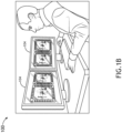
- FIGS. 1A-1C in general illustrate an avionics lower level device (LLD) simulator 100, in accordance with one or more embodiments of the disclosure.
- LLD avionics lower level device
- the LLD simulator 100 may be configured in accordance with guidelines and/or standards put forth by, but not limited to, the Federal Aviation Administration (FAA), the European Aviation Safety Agency (EASA) or any other flight certification agency or organization; the American National Standards Institute (ANSI), Aeronautical Radio, Incorporated (ARINC), or any other standards setting organization or company; the Radio Technical Commission for Aeronautics (RTCA) or any other guidelines agency or organization; or the like.
- FAA Federal Aviation Administration
- EASA European Aviation Safety Agency
- ARINC Aeronautical Radio, Incorporated
- RTCA Radio Technical Commission for Aeronautics
- the LLD simulator 100 may be designed in accordance with guidelines and/or standards put forth in ARINC 610, GUIDANCE FOR DESIGN AND INTEGRATION OF AIRCRAFT AVIONICS EQUIPMENT IN SIMULATORS, as last published February 1, 1992.
- the LLD simulator 100 may include a main chassis or body 102.
- the main chassis or body 102 may represent a flight deck of a cockpit.
- the LLD simulator 100 may include or be coupled to one or more instrument panel touchscreen display devices 104 coupled to the main chassis or body 102.
- the LLD simulator 100 may include an upper chassis or body 106.
- the LLD simulator 100 may include or be coupled to one or more windshield or other line-of-sight touchscreen display devices 108 coupled to the upper chassis or body 106.
- the one or more windshield or other line-of-sight touchscreen display devices 108 may be configured to display actual or emulated environmental conditions.
- the LLD simulator 100 may include a center console 110.
- the center console 110 may represent a pedestal of the cockpit.
- the LLD simulator 100 may include or be coupled to one or more primary flight control touchscreen display devices 112 coupled to the center console 110.
- the one or more primary flight control touchscreen display devices 112 may include primary flight controls directly involved in flying an aircraft.
- the LLD simulator 100 may include an overhead chassis or body 114.
- the LLD simulator 100 may include or be coupled to one or more secondary control touchscreen display devices 116.
- the one or more secondary control touchscreen display devices 116 may include secondary aircraft controls not directly involved in flying an aircraft.
- the LLD simulator 100 may include one or more side consoles 118.
- the LLD simulator 100 may include or be coupled to one or more side console touchscreen display devices 120.
- the one or more side console touchscreen display devices 120 may include controls for communication instruments, documentation, or the like.
- main chassis or body 102, the upper chassis or body 106, the center console 110, the overhead chassis or body 114, and/or the one or more side consoles 118 may be considered cockpit sections emulated by or within a select arrangement or build of the LLD simulator 100, for purposes of the present disclosure.
- cockpit sections 102, 106, 110, 114, 118 it is noted herein one or more of the cockpit sections 102, 106, 110, 114, 118 may be combined or integrated into a single component. Therefore, the above description should not be interpreted as a limitation on the disclosure but merely an illustration.
- embodiments of the disclosure illustrate select touchscreen display devices 104, 108, 112, 116, 120 coupled to corresponding cockpit sections 102, 106, 110, 114, 118
- the disclosure is not limited to the particular arrangement.
- the select touchscreen display devices 104, 108, 112, 116, 120 coupled to different or multiples of the different cockpit sections 102, 106, 110, 114, 118.
- the LLD simulator 100 may be limited in the number of select touchscreen display devices 104, 108, 112, 116, 120 coupled to corresponding cockpit sections 102, 106, 110, 114, 118 (e.g., where the LLD simulator 100 is a table-top simulator such as a desktop computer build). Therefore, the above description should not be interpreted as a limitation on the disclosure but merely an illustration.
- the LLD simulator 100 may include components (e.g., physical or imaged components) for a joystick, yoke, seat, headset, helmet, rudder pedals / brake pedals, footrests, or the like.
- the LLD simulator 100 may be dimensioned for floor or platform installation or usage (e.g., as illustrated in FIG. 1A ), such that the LLD simulator 100 may emulate a cockpit of an aircraft.
- the LLD simulator 100 may be dimensioned for table-top installation or usage (e.g., as illustrated in FIGS. 1B and 1C ).
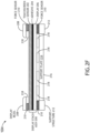
- FIGS. 2A-2F in general illustrate cross-sectional diagrams of a portion of a touchscreen display device 104 of the LLD simulator 100.
- the examples shown in Figs. 2A to 2E are not within the scope of the invention as claimed and are included for background only.
- the example of Fig. 2F is an embodiment of the invention as defined by the claims.
- the touchscreen display device 104 may include, but is not limited to, a capacitive touchscreen display device such as, but not limited to, a Projected Capacitive Touch (PCT) touchscreen display device (e.g., a mutual capacitance PCT touchscreen display device, a self-capacitance PCT touchscreen display device, or the like).
- the touchscreen display device 104 may include, but is not limited to, a resistive touchscreen display device.
- the touchscreen display device 104 may include, but is not limited to, a beam interrupt touchscreen display device (e.g., such as an infrared grid touchscreen device).
- the touchscreen display device 104 may include, but is not limited to, an optical touchscreen display device.
- the touchscreen display device 104 may include, but is not limited to, a touchscreen display device configured to detect piezoelectricity in glass due to a touch.
- the touchscreen display device 104 may include a display stack assembly 200.
- the display stack assembly 200 may include may include one or more touchscreen sensors 202.
- the one or more touchscreen sensors 202 may be configured to sense a touch or near touch (such as a finger or apparatus (e.g., a stylus or glove) in proximity to a user-interfaceable surface of the touchscreen display device 104) of the touchscreen display device 104.
- the one or more touchscreen sensors 202 may include a transparent conductor layer (such as indium tin oxide (ITO)) deposited on an insulator substrate (such as glass), which results in a measurable change in capacitance when the surface of the one or more touchscreen sensors 202 is touched or nearly touched.
- ITO indium tin oxide
- the one or more touchscreen sensors 202 may include an array (e.g., an X-Y grid) of pairs of beam emitters (e.g., light emitting diodes (LEDs)) and sensors (e.g., photodetectors) configured to detect a disruption of a beam or beam pattern during the occurrence of a touch or near touch of the touchscreen display device 104.
- the one or more touchscreen sensors 202 may be configured to output data (e.g., touch location information as signals or a change in electrical properties) to a controller, a processor, or other computing device as described throughout the disclosure.
- the display stack assembly 200 may include an adhesive layer 204.
- the display stack assembly 200 may include a display 206.
- the adhesive layer 204 may include a transparent adhesive positioned between the display 206 and the one or more touchscreen sensors 202.
- the adhesive layer 204 may bond the display 206 to a substrate of the one or more touchscreen sensors 202.
- the adhesive layer 204 may be omitted.
- another adhesive layer may bond a bottom surface of the display 206 to a rigid or substantially rigid substrate below the display 206.
- the display 206 may be implemented as display element configured to impart an image for presentation to user.
- the display 206 is implemented as a transmissive display element, an emissive display element, as well as other types of display elements.
- the display 206 may be transmissive display element implemented as a liquid crystal display (LCD) element.
- the display 206 may be implemented as an organic light-emitting diode (OLED) display element, such as active-matrix OLEDs (AMOLEDs), passive-matrix OLEDs (PMOLEDs), light-emitting electrochemical cells (LECs), or the like.
- the display 206 may be implemented as an in-cell or on-cell LCD display element such that the LCD display element and the touchscreen sensor 202 are implemented in a single layer.
- the display stack assembly 200 may include a rigid or substantially rigid substrate.
- the touchscreen display device 104 may include a display bezel 208
- the display stack assembly 200 may be positioned proximate to the display bezel 208.
- the display bezel 208 may fully or partially surround an edge of the display stack assembly 200.
- the display bezel 208 may be positioned on top of the display stack assembly 200.
- the display bezel 208 may at least partially enclose (e.g., cover a portion of a side) of the display stack assembly 200.
- the touchscreen display device 104 may include one or more force sensors 210 positioned proximate to the display stack assembly 200.
- the one or more force sensors 210 may be configured to detect an amount of force (e.g., compressive force) acting on (e.g., applied by a user when the user is touching a user-interfaceable surface of the touchscreen display device 104) on the force sensor 210.
- the one or more force sensors 210 may be implemented as conductive polymer force sensors, piezoelectric force sensors, other suitable force sensors, or a combination of the above.
- the one or more force sensors 210 may be configured to output data (e.g., touch force information as signals or a change in electrical properties) to a controller, a processor, or other computing device as described throughout the disclosure.
- the one or more force sensors 210 may be opaque, may be transparent, or may be a combination of opaque force sensors and transparent force sensors.
- the one or more force sensors 210 may be positioned below the display 206 and along the edges of the display 206. It is noted herein, however, that the one or more force sensors 210 may be implemented in any of various suitable locations and/or configurations. For example, the one or more force sensors 210 may be positioned below, above, or within the display stack assembly 200. By way of another example, a single force sensor 210 may be implemented as a ring (e.g., rectangular ring) located below or above the display 206 and in proximity to the edges of the display 206. By way of another example, the one or more force sensors 210 may be implemented as strips, where each strip is located along an edge of the display 206.
- the one or more force sensors 210 may be arranged in an array (e.g., rows, columns, a grid of rows and columns, arranged in a pattern of concentric circles, or the like) of transparent force sensors arranged across (e.g., in a plane above, below, or within the display stack assembly 200) the display 206 (e.g. a transmissive display). Therefore, the above description should not be interpreted as a limitation on the disclosure but merely an illustration.
- the touchscreen display device 104 may include a support structure 212.
- the display stack assembly 200 may be positioned proximate to the support structure 212.
- the support structure 212 may include, but is not limited to, a support frame, such as a display stack support frame.
- the touchscreen display device 104 may include a support plate 214 positioned proximate to the support structure 212.
- the display stack assembly 200 may be positioned proximate to the support plate 214.
- the touchscreen display device 104 may include a backlight 216.
- the display stack assembly 200 may be positioned proximate to the backlight 216.
- the touchscreen display device 104 may include one or more advanced haptic feedback components 218 positioned proximate to the display stack assembly 200.
- the one or more advanced haptic feedback components 218 may include, but are not limited to, components fabricated from piezoelectric technologies and/or components with piezoelectric functions or operations.
- the touchscreen display device 104 may include one or more other components such as, but not limited to, a cover transparent substrate, light control films, polarizing films, a gap, a diffuser, a housing, communicative coupling elements (e.g., wires, cables, connectors, etc.), connectivity ports, a power supply, a processor, a circuit board (e.g., printed circuit board (PCB)), a controller, memory, storage, an antenna, or the like. Some or all of the components of the touchscreen display device 104 may be communicatively coupled.
- a cover transparent substrate such as, but not limited to, a cover transparent substrate, light control films, polarizing films, a gap, a diffuser, a housing, communicative coupling elements (e.g., wires, cables, connectors, etc.), connectivity ports, a power supply, a processor, a circuit board (e.g., printed circuit board (PCB)), a controller, memory, storage, an antenna, or the like.
- the display stack assembly 200 may be positioned between a display bezel 208 and one or more force sensors 210.
- the display bezel 208 may be positioned above the display stack assembly 200.
- the display stack assembly 200 may be positioned between the display bezel 208, on the top side, and the one or more force sensors 210 and the backlight 216, on the bottom side.
- the one or more force sensors 210 may be positioned between the display stack assembly 200 and the support structure 212, and the one or more force sensors 210 are positioned under the edges of the display stack assembly 200.
- the backlight 216 may be positioned under the display stack assembly 200 and between the support structure 212.
- the display bezel 208 may be positioned above one or more force sensors 210 and the display stack assembly 200.
- the one or more force sensors 210 may be positioned between the display bezel 208 and the display stack assembly 200 along the edges of the display stack assembly 200.
- the display stack assembly 200 may be positioned between the display bezel 208 and one or more force sensors 210, on the top side, and one or more additional force sensors 210 and the backlight 216, on the bottom side.
- the one or more additional force sensors 210 may be positioned between the display stack assembly 200 and the support structure 212, and the one or more additional force sensors 210 may be positioned under the edges of the display stack assembly 200.
- the backlight 216 may be positioned under the display stack assembly 200 and between the support structure 212.
- the touchscreen sensor 202 may be implemented in the display 206 within the display stack assembly 200.
- the display stack assembly 200 may be positioned between a display bezel 208 and one or more force sensors 210.
- the display bezel 208 may be positioned above the display stack assembly 200.
- the display stack assembly 200 may be positioned between the display bezel 208, on the top side, and the one or more force sensors 210 and the backlight 216, on the bottom side.
- the one or more force sensors 210 may be positioned between the display stack assembly 200 and the support structure 212, and the one or more force sensors 210 are positioned under the edges of the display stack assembly 200.
- the backlight 216 may be positioned under the display stack assembly 200 and between the support structure 212.
- the display bezel 208 may be positioned above the display stack assembly 200.
- the display stack assembly 200 may be positioned between the display bezel 208, on the top side, the one or more force sensors 210, and the one or more advanced haptic feedback components 218 on the bottom side.
- the one or more force sensors 210 may be positioned between the display stack assembly 200 and the support structure 212, and the one or more force sensors 210 are positioned under the edges of the display stack assembly 200.
- the one or more advanced haptic feedback components 218 may be positioned between the display stack assembly 200 and the support plate 214, and the one or more advanced haptic feedback components 218 may be generally positioned under the viewable portion of the display 206.
- the support plate 214 may be positioned under the one or more advanced haptic feedback components 218 and between the support structure 212.
- the backlight 216 may be positioned under the display stack assembly 200 and between the support structure 212.
- the display bezel 208 may be positioned above the one or more force sensors 210 and the display stack assembly 200.
- the one or more force sensors 210 may be positioned between the display bezel 208 and the display stack assembly 200 along the edges of the display stack assembly 200.
- the display stack assembly 200 may be positioned between the display bezel 208 and the one or more force sensors 210, on the top side, the one or more additional force sensors 210, and the one or more advanced haptic feedback components 218 on the bottom side.
- the one or more additional force sensors 210 may be positioned between the display stack assembly 200 and the support structure 212, and the one or more additional force sensors 210 may be positioned under the edges of the display stack assembly 200.
- the one or more advanced haptic feedback components 218 may be positioned between the display stack assembly 200 and the support plate 214, and the one or more advanced haptic feedback components 218 may be generally positioned under the viewable portion of the display 206.
- the support plate 214 may be positioned under the one or more advanced haptic feedback components 218 and between the support structure 212.
- the backlight 216 may be positioned under the display stack assembly 200 and between the support structure 212.
- the display bezel 208 may be positioned above the one or more force sensors 210, the one or more advanced haptic feedback components 218, and the display stack assembly 200.
- the one or more force sensors 210 and the one or more advanced haptic feedback components 218 may be positioned between the display bezel 208 and the display stack assembly 200 along the edges of the display stack assembly 200.
- the display stack assembly 200 may be positioned between the display bezel 208, the one or more force sensors 210, and the one or more advanced haptic feedback components 218, on the top side, the one or more additional force sensors 210, and one or more additional advanced haptic feedback components 218 on the bottom side.
- the one or more additional force sensors 210 may be positioned between the display stack assembly 200 and the support structure 212, and the one or more additional force sensors 210 may be positioned under the edges of the display stack assembly 200.
- the one or more advanced haptic feedback components 218 may be positioned between the display stack assembly 200 and the support plate 214, and the one or more advanced haptic feedback components 218 may be generally positioned under the viewable portion of the display 206.
- the support plate 214 may be positioned under the one or more advanced haptic feedback components 218 and between the support structure 212.
- the backlight 216 may be positioned under the display stack assembly 200 and between the support structure 212. It is noted herein, however, that the backlight 216 may not be included in the embodiment illustrated in FIG. 2F . While FIG. 2F depicts one embodiment having an exemplary arrangement of components of the touchscreen display device 104, other embodiments may include any suitable arrangements of the same or other components.
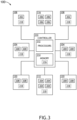
- FIG. 3 illustrates the avionics LLD simulator 100, in accordance with one or more embodiments of the disclosure.
- FIGS. 4 and 5 in general illustrate methods or processes for generating advanced haptics in touchscreen avionics lower level device simulators, in accordance with one or more embodiments of the disclosure.
- the embodiments illustrated in FIGS. 2A-2F with respect to the touchscreen display device 104 should be understood to be applicable to the touchscreen display devices 104, 108, 112, 116, 120 illustrated in FIG. 3 .
- the touchscreen display devices 104, 108, 112, 116, 120 as illustrated in FIG. 3 may include one or more of the display stack assembly 200 with the one or more touchscreen sensors 202, the adhesive layer 204, and/or the display 206, the display bezel 208, the one or more force sensors 210, the one or more support structures 212, the support plate 214, the backlight 216, and/or the one or more advanced haptic feedback components 218.
- the touchscreen display devices 104, 108, 112, 116, 120 may be configured to display one or more graphical user interfaces (GUIs) and/or GUI icons related to an operation of one or more internal components or external components on an aircraft.
- GUIs graphical user interfaces
- the touchscreen display devices 104, 108, 112, 116, 120 may be generally configured to display electronic maps, aircraft performance parameters, aircraft performance parameter predictions, sensor readings, aircraft data, flight data, communications, alerts, and the like.
- the touchscreen display devices 104, 108, 112, 116, 120 may include, but are not limited to, one or more primary flight display devices and/or one or more multi-function display devices that are viewable by a user. It is noted herein, however, that the LLD simulator 100 may include any number of touchscreen display devices 104, 108, 112, 116, 120 (e.g., one, two, three, or more touchscreen display devices 104, 108, 112, 116, 120) including one or more primary flight display devices, secondary flight display devices, and/or multi-function display devices.
- the one or more instrument panel touchscreen display devices 104 may be configured to display one or more GUIs and/or GUI icons related to or representing one or more aircraft instruments 300.
- the one or more aircraft instruments 300 may include, but are not limited to, a primary flight display, a secondary flight display, a multi-function flight display, an airspace indicator, an altitude indicator, an artificial horizon indicator, a direction finder (e.g., directional gyroscope), a turn and/or tilt indicator, a vertical velocity indicator, a bank of navigation controls, a systems information display, marker beacons, an automatic direction finder (ADF), a distance measurement equipment (DME), a transponder, a radar display, a Global Positioning System (GPS), or the like.
- ADF automatic direction finder
- DME distance measurement equipment
- GPS Global Positioning System
- the one or more windshield or other line-of-sight touchscreen display devices 108 may be configured to display one or more GUIs and/or GUI icons related to or representing actual or emulated environmental conditions 302.
- the one or more environmental conditions 302 may include, but are not limited to, a runway, a hanger, an obstacle, sky, water, land, or the like.
- the one or more center console touchscreen display devices 112 may be configured to display one or more GUIs and/or GUI icons related to or representing one or more primary aircraft controls 304.
- the one or more primary aircraft controls 304 may include, but are not limited to, engine and navigation controls 304 coupled to the center console 110.
- the primary aircraft controls 304 may include, but are not limited to, throttle levers, user input devices (e.g., keyboards, or the like) for various navigational systems displayed on the one or more instrument panels touchscreen display devices 104 and/or various communication systems displayed on the one or more side console touchscreen display devices 120, or the like.
- the one or more secondary control touchscreen display devices 116 may be configured to display one or more GUIs and/or GUI icons related to or representing one or more secondary aircraft controls 306.
- the one or more secondary aircraft controls 306 may include, but are not limited to, anti-ice controls, air conditioning controls, cabin pressurization controls, oxygen controls, or the like.
- the one or more side console touchscreen display devices 120 may be configured to display one or more GUIs and/or GUI icons related to or representing one or more side console aircraft controls or documentation 308.
- the one or more side console aircraft controls 308 may include, but not limited to, communication instrument controls, documentation, or the like.
- the LLD simulator 100 may be configured to generate one or more advanced haptic feedback responses via the touchscreen display devices 104, 108, 112, 116, 120 coupled to corresponding cockpit sections 102, 106, 110, 114, 118.
- the one or more feedback responses may include one or more advanced haptic feedback responses (e.g., an advanced tactile response and/or an advanced kinesthetic response).
- the one or more feedback responses may include one or more visual feedback responses (e.g., one or more lights).
- the one or more feedback responses may include one or more auditory feedback responses (e.g., one or more sounds).
- the one or more feedback responses may include one or more graphical feedback responses (e.g., one or more displayed icons). It is noted herein the LLD simulator 100 may be configured to generate one or more feedback response of multiple types (e.g., advanced haptic feedback responses and visual feedback responses, or any other combination).
- interaction with the one or more GUIs and/or GUI icons related to the controls 300, 302, 304, 306, 308 may be configured to provide a user with one or more advanced haptic responses.
- the one or more advanced haptic responses may be feedback beyond a simple vibration.
- the one or more advanced haptic responses may be specific to and/or otherwise dependent on the input received via the touchscreen display devices 104, 108, 112, 116, 120 following an interaction of the touchscreen display devices 104, 108, 112, 116, 120 by a user, such that different inputs received may result in different advanced haptic responses.
- the advanced haptic responses may be defined by one or more metrics including, but not limited to, a pattern, a relief or texture, a wavelength, a rate of flash, a duration, intensity, elasticity, or other metric that defines an operation of a mechanical component.
- the one or more metrics may be constant or variable.
- the one or more metrics may be pre-set (e.g., stored within program instructions of one or more controllers installed in or coupled to the one or more LLD simulator 100) or may be adjustable.
- the one or more advanced haptic responses may be a more efficient indication of successful interaction with the touchscreen display devices 104, 108, 112, 116, 120 by the user (e.g., than may be possible via a binary on/off pairing for any type of relayed information such as a call-and-response vibration).
- the advanced haptic responses may provide an advanced mimicry of a button resistance (e.g., as might be generated by a membrane or spring) when transitioning to a depressed state, and a return of the button to an original state upon release.
- a button resistance e.g., as might be generated by a membrane or spring
- the advanced haptic responses may provide an advanced mimicry of a toggle switch snap, which may represent a resistance of a toggle switch between a first state and an intermediate transition point and a reduced resistance of the toggle switch between the intermediate transition point and a second state.
- the advanced haptic responses may provide an advanced mimicry of a knob click, which may represent a resistance of a knob between a first state between a first state and an intermediate transition point and a reduced resistance of the knob between the intermediate transition point and a second state.
- the touchscreen display devices 104, 108, 112, 116, 120 with the advanced haptic feedback components 218 may be configured for multi-touch.
- the advanced haptic responses may be local (e.g., at the location of the controls 300, 302, 304, 306, 308) such that each advanced haptic response may be separate and distinct from other advanced haptic responses with respect to the one or more above-defined metrics.
- the advanced haptic responses may be partially or fully global across the entire respective touchscreen display device 104, 108, 112, 116, 120 such that the advanced haptic responses may be similar with respect to the one or more above-defined metrics.
- the advanced haptic responses may provide a user using the LLD simulator 100 with a more advanced haptic response to their interactions with the one or more GUIs and/or GUI icons related to the controls 300, 302, 304, 306, 308 on the touchscreen display device 104, 108, 112, 116, 120 of the LLD simulator 100 during one or more training procedures beyond a simple vibration.
- the advanced haptic responses may allow for the LLD simulator 100 to be constructed with the touchscreen display devices 104, 108, 112, 116, 120 instead of mechanical components while still providing an advanced haptic feedback similar to that provided by mechanical components, leading a reduced cost and/or size of footprint of the LLD simulator 100 as compared to a full-flight or high-level simulator.
- Interacting with the displayed GUIs and/or GUI icons related to the controls 300, 302, 304, 306, 308 may cause changes in the displayed GUIs and/or GUI icons on the respective touchscreen display devices 104, 108, 112, 116, 120.
- interacting with the one or more instruments 300 displayed on the one or more instrument panel touchscreen display devices 104 may cause a change in what is being displayed for the one or more instruments 300 on the one or more instrument panel touchscreen display devices 104.
- Interacting with the displayed GUIs and/or GUI icons related to the controls 300, 302, 304, 306, 308 may cause changes in the displayed GUIs and/or GUI icons on different touchscreen display devices 104, 108, 112, 116, 120.
- a primary aircraft control 304 e.g., a keyboard, or the like
- displayed on the one or more center console touchscreen display devices 112 may cause a change in what is being displayed for the one or more instruments 300 on the one or more instrument panel touchscreen display devices 104.
- FIG. 4 illustrates a method or process 400 for generating advanced haptics in touchscreen avionics lower level device simulators, in accordance with one or more embodiments of the disclosure.
- a user input may be received from a touchscreen display device.
- the user input may be received from the touchscreen display devices 104, 108, 112, 116, and/or 120 installed on an LLD simulator 100.
- the user input may be with respect to the controls 300, 302, 304, 306, and/or 308 displayed on the touchscreen display devices 104, 108, 112, 116, and/or 120, where the controls 300, 302, 304, 306, and/or 308 are related to a simulated function or operation of an aircraft.
- an advanced haptic response signal may be generated.
- the advanced haptic response signal may be configured to cause an advanced haptic feedback mimicking a physical response observed following an operation of mechanical components installed within a cockpit of an aircraft, the mechanical components being related to the controls 300, 302, 304, 306, and/or 308 displayed on the touchscreen display devices 104, 108, 112, 116, and/or 120.
- the advanced haptic response signal may generate an advanced haptic response defined by one or more metrics of a physical response observed following an operation of mechanical components.
- the advanced haptic response signal may be transmitted to one or more advanced haptic feedback components.
- the one or more advanced haptic feedback components 218 may be installed in the same touchscreen display device 104, 108, 112, 116, and/or 120 on which the interacted-with controls 300, 302, 304, 306, and/or 308 are displayed.
- the one or more advanced haptic feedback components 218 may be installed in different touchscreen display devices 104, 108, 112, 116, and/or 120 from the touchscreen display devices 104, 108, 112, 116, and/or 120 on which the interacted-with controls 300, 302, 304, 306, and/or 308 are displayed.
- FIG. 5 illustrates a method or process 500 for generating advanced haptics in touchscreen avionics lower level device simulators, in accordance with one or more embodiments of the disclosure.
- a user input may be transmitted.
- the user input may be transmitted to one or more controllers installed in an LLD simulator 100, either directly or within one or more touchscreen display devices 104, 108, 112, 116, and/or 120 installed on the LLD simulator 100.
- an advanced haptic response signal may be received.
- the advanced haptic response signal may be configured to cause an advanced haptic feedback mimicking the operation of mechanical components related to the controls 300, 302, 304, 306, and/or 308 displayed on the touchscreen display devices 104, 108, 112, 116, and/or 120.
- the advanced haptic response signal may generate an advanced haptic response defined by one or more metrics that mimic an operation of a mechanical component within the one or more advanced haptic feedback components 218.
- advanced haptic feedback may be generated based on the advanced haptic response signal.
- the one or more advanced haptic feedback components 218 may be installed in the same touchscreen display device 104, 108, 112, 116, and/or 120 on which the interacted-with controls 300, 302, 304, 306, and/or 308 are displayed.
- the one or more advanced haptic feedback components 218 may be installed in different touchscreen display devices 104, 108, 112, 116, and/or 120 from the touchscreen display devices 104, 108, 112, 116, and/or 120 on which the interacted-with controls 300, 302, 304, 306, and/or 308 are displayed.
- the methods or processes 400 or 500 are not limited to the steps and/or sub-steps provided.
- the methods or processes 400 or 500 may include more or fewer steps and/or sub-steps.
- the methods or processes 400 or 500 may perform the steps and/or sub-steps simultaneously.
- the methods or processes 400 or 500 may perform the steps and/or sub-steps sequentially, including in the order provided or an order other than provided. Therefore, the above description should not be interpreted as a limitation on the scope of the disclosure but merely an illustration.
- the LLD simulator 100 may include one or more controllers 310.
- the one or more controllers 310 may include one or more processors 312 and memory 314.
- the memory 314 may store one or more sets of program instructions.
- the one or more processors 312 may be configured to execute the one or more sets of program instructions to carry out one or more of the various steps described throughout the disclosure.
- the one or more controllers 310 may include one or more communication interfaces.
- the one or more communication interfaces may include via wired means or via wireless means (e.g., via Bluetooth, Wi-Fi, Near Field Communication (NFC), or the like), where the one or more communication interfaces may be configured to receive data, transmit data, transmit power, or otherwise interact with the other controllers in the LLD simulator 100.
- wireless means e.g., via Bluetooth, Wi-Fi, Near Field Communication (NFC), or the like
- the LLD simulator 100 may include one or more touchscreen display device controllers 318.
- the one or more touchscreen display device controllers 318 may include one or more processors and memory.
- the memory may store one or more sets of program instructions.
- the one or more processors may be configured to execute the one or more sets of program instructions to carry out one or more of the various steps described throughout the disclosure.
- the one or more controllers 310 may include one or more communication interfaces.
- the one or more controllers 310 may be coupled (e.g., physically, electrically, and/or communicatively coupled) to the one or more touchscreen display device controllers 318.
- the one or more controllers 310 may transmit power, control signals, data, or the like (e.g., one or more signals) to the one or more touchscreen display device controllers 318.
- the one or more controllers 310 may receive power, control signals, data, or the like (e.g., the one or more signals) from the one or more components in the one or more touchscreen display device controllers 318.
- the one or more processors 312 may include any one or more processing elements known in the art. In this sense, the one or more processors 312 may include any microprocessor device configured to execute algorithms and/or program instructions. In general, the term "processor" may be broadly defined to encompass any device having one or more processing elements, which execute a set of program instructions from a non-transitory memory medium (e.g., the memory 314), where the one or more sets of program instructions are configured to cause the one or more processors 312 to carry out any of one or more process steps.
- a non-transitory memory medium e.g., the memory 314.
- the memory 314 may include any storage medium known in the art suitable for storing the one or more sets of program instructions executable by the associated one or more processors 312.
- the memory 314 may include a non-transitory memory medium.
- the memory 314 may include, but is not limited to, a read-only memory (ROM), a random access memory (RAM), a magnetic or optical memory device (e.g., disk), a magnetic tape, a solid state drive, and the like.
- the memory 314 may be configured to provide display information to the one or more touchscreen display devices 104, 108, 112, 116, 120.
- the memory 314 may be configured to store user input information from one or more user input devices.
- the memory 314 may be housed in a common controller housing with the one or more processors 312.
- the memory 314 may, alternatively or in addition, be located remotely with respect to the spatial location of the processors 312, the one or more controllers 310 and/or the one or more touchscreen display device controllers.
- the one or more processors 312, the one or more controllers 310, and/or the one or more touchscreen display device controllers may access a remote memory 314 (e.g., server), accessible through a network (e.g., internet, intranet, and the like) via one or more communication interfaces.
- a remote memory 314 e.g., server
- a network e.g., internet, intranet, and the like
- the one or more communication interfaces may be operatively configured to communicate with one or more components of the one or more controllers 310 and/or the one or more components of the one or more touchscreen display device controllers.
- the one or more communication interfaces may also be coupled (e.g., physically, electrically, and/or communicatively) with the one or more processors 312 to facilitate data transfer between components of the one or more components of the one or more controllers 310 and/or the one or more components of the one or more touchscreen display device controllers and the one or more processors 312.
- the one or more communication interfaces may be configured to retrieve data from the one or more processors 312, or other devices, transmit data for storage in the memory 314, retrieve data from storage in the memory 314, or the like.
- the one or more touchscreen display device controllers and/or one or more offboard controllers may be configured to receive and/or acquire data or information from other systems or tools by a transmission medium that may include wireline and/or wireless portions.
- the one or more touchscreen display device controllers and/or the one or more offboard controllers may be configured to transmit data or information (e.g., the output of one or more procedures of the inventive concepts disclosed herein) to one or more systems or tools by a transmission medium that may include wireline and/or wireless portions (e.g., a transmitter, receiver, transceiver, physical connection interface, or any combination).
- the transmission medium may serve as a data link between the one or more touchscreen display device controllers and/or the one or more offboard controllers and the other subsystems (e.g., of the aircraft 302).
- the one or more touchscreen display device controllers and/or the one or more offboard controllers may be configured to send data to external systems via a transmission medium (e.g., network connection).
- the disclosure is directed to the one or more controllers 310 and the one or more touchscreen display device controllers being separate, it is noted herein the one or more controllers 310 and the one or more touchscreen display device controllers may be the same and/or share select components. Therefore, the above description should not be interpreted as a limitation on the disclosure but merely an illustration.
- the disclosure is directed to the touchscreen display devices 104, 108, 112, 116, 120 including the one or more touchscreen display device controllers 318, it is noted herein, however, that the one or more touchscreen display device controllers 318 may be not present, and that the one or more controllers 310 may have direct control over the touchscreen display devices 104, 108, 112, 116, 120 and/or components of the touchscreen display devices 104, 108, 112, 116, 120.
Landscapes
- Engineering & Computer Science (AREA)
- Theoretical Computer Science (AREA)
- General Engineering & Computer Science (AREA)
- Physics & Mathematics (AREA)
- General Physics & Mathematics (AREA)
- Human Computer Interaction (AREA)
- Aviation & Aerospace Engineering (AREA)
- Business, Economics & Management (AREA)
- Educational Administration (AREA)
- Educational Technology (AREA)
- Computer Hardware Design (AREA)
- User Interface Of Digital Computer (AREA)
Claims (10)
- Avioniksimulator für Vorrichtungen der unteren Ebene (Lower Level Device - LLD), umfassend:
mindestens eine Touchscreen-Anzeigevorrichtung (120), wobei die mindestens eine Touchscreen-Anzeigevorrichtung Folgendes umfasst:
eine Anzeigestapelbaugruppe (200), die mindestens einen Touchscreen-Sensor (202) und eine Anzeige (206) beinhaltet; und gekennzeichnet durch:mindestens eine fortschrittliche haptische Rückmeldungskomponente (218), die in der Nähe der Anzeigestapelbaugruppe positioniert ist; undmindestens einen Kraftsensor (210), der in der Nähe der mindestens einen fortschrittlichen haptischen Rückmeldungskomponente positioniert ist und zum Erfassen einer Druckkraft konfiguriert ist;wobei die mindestens eine fortschrittliche haptische Rückmeldungskomponente und der mindestens eine Kraftsensor zwischen einer Anzeigeblende der mindestens einen Touchscreen-Anzeigevorrichtung und der Anzeigestapelbaugruppe positioniert sind;wobei die mindestens eine Touchscreen-Anzeigevorrichtung dazu konfiguriert ist, mindestens eine GUI oder mindestens ein GUI-Symbol anzuzeigen, wobei die mindestens eine GUI oder das mindestens eine GUI-Symbol eine Bedienung eines Flugzeugs betrifft,wobei die mindestens eine fortschrittliche haptische Rückmeldungskomponente dazu konfiguriert ist, nach einer Interaktion mit der mindestens einen GUI oder dem mindestens einen GUI-Symbol, die bzw. das auf der mindestens einen Touchscreen-Anzeigevorrichtung angezeigt wird, mindestens eine fortschrittliche haptische Rückmeldungsreaktion bereitzustellen, wobei die fortschrittliche haptische Rückmeldungsreaktion mindestens eine von einer fortschrittlichen taktilen Reaktion oder einer fortschrittlichen kinästhetischen Reaktion beinhaltet,wobei die mindestens eine fortschrittliche haptische Rückmeldungsreaktion dazu konfiguriert ist, eine physische Reaktion nachzuahmen, die nach einer Bedienung einer in einem Cockpit des Flugzeugs installierten mechanischen Komponente beobachtet wird. - Avionik-LLD-Simulator nach Anspruch 1, wobei die mindestens eine Touchscreen-Anzeigevorrichtung ferner Folgendes umfasst:
eine oder mehrere von einer Hintergrundbeleuchtung (216), einer Trägerstruktur (212) oder einer Trägerplatte (214), wobei die Anzeigestapelbaugruppe in der Nähe der einen oder mehreren von der Hintergrundbeleuchtung, der Trägerstruktur oder der Trägerplatte positioniert ist. - Avionik-LLD-Simulator nach einem der vorhergehenden Ansprüche, wobei die mindestens eine Touchscreen-Anzeigevorrichtung eine Instrumententafel-Touchscreen-Anzeigevorrichtung beinhaltet, die dazu konfiguriert ist, mindestens eine GUI oder mindestens ein GUI-Symbol, die bzw. das ein Flugzeuginstrument darstellt, anzuzeigen.
- Avionik-LLD-Simulator nach einem der vorhergehenden Ansprüche, wobei die mindestens eine Touchscreen-Anzeigevorrichtung eine Windschutzscheiben-Touchscreen-Anzeigevorrichtung beinhaltet, die dazu konfiguriert ist, mindestens eine GUI oder mindestens ein GUI-Symbol, die bzw. das eine tatsächliche oder emulierte Umgebungsbedingung darstellt, anzuzeigen.
- Avionik-LLD-Simulator nach einem der vorhergehenden Ansprüche, wobei die mindestens eine Touchscreen-Anzeigevorrichtung eine Touchscreen-Anzeigevorrichtung für eine primäre Flugsteuerung beinhaltet, die dazu konfiguriert ist, mindestens eine GUI oder mindestens ein GUI-Symbol, die bzw. das eine primäre Flugsteuerung darstellt, anzuzeigen.
- Avionik-LLD-Simulator nach einem der vorhergehenden Ansprüche, wobei die mindestens eine Touchscreen-Anzeigevorrichtung eine Touchscreen-Anzeigevorrichtung für eine sekundäre Steuerung beinhaltet, die dazu konfiguriert ist, mindestens eine GUI oder mindestens ein GUI-Symbol, die bzw. das eine sekundäre Flugzeugsteuerung darstellt, anzuzeigen.
- Avionik-LLD-Simulator nach einem der vorhergehenden Ansprüche, wobei die mindestens eine Touchscreen-Anzeigevorrichtung eine Seitenkonsolen-Touchscreen-Anzeigevorrichtung beinhaltet, die dazu konfiguriert ist, mindestens eine GUI oder mindestens ein GUI-Symbol, die bzw. das eine Seitenkonsolen-Flugzeugsteuerung darstellt, anzuzeigen.
- Avionik-LLD-Simulator nach einem der vorhergehenden Ansprüche, wobei die mechanische Komponente eine Taste, einen Drehknopf, einen Schalter oder einen Hebel, die in dem Cockpit des Flugzeugs installiert sind, beinhaltet.
- Avioniksimulator für Vorrichtungen der unteren Ebene (LLD), umfassend:mindestens einen Cockpitbereich; undmindestens eine Touchscreen-Anzeigevorrichtung (120), die an den mindestens einen Cockpitbereich gekoppelt ist, wobei die mindestens eine Touchscreen-Anzeigevorrichtung Folgendes umfasst:
eine Anzeigestapelbaugruppe (200), die mindestens einen Touchscreen-Sensor (202) und eine Anzeige (206) beinhaltet; und gekennzeichnet durch:mindestens eine fortschrittliche haptische Rückmeldungskomponente (218), die in der Nähe der Anzeigestapelbaugruppe positioniert ist; undmindestens einen Kraftsensor (210), der in der Nähe der mindestens einen fortschrittlichen haptischen Rückmeldungskomponente positioniert ist und zum Erfassen einer Druckkraft konfiguriert ist;wobei die mindestens eine fortschrittliche haptische Rückmeldungskomponente und der mindestens eine Kraftsensor zwischen einer Anzeigeblende der mindestens einen Touchscreen-Anzeigevorrichtung und der Anzeigestapelbaugruppe positioniert sind;wobei die mindestens eine Touchscreen-Anzeigevorrichtung dazu konfiguriert ist, mindestens eine GUI oder mindestens ein GUI-Symbol anzuzeigen, wobei die mindestens eine GUI oder das mindestens eine GUI-Symbol eine Bedienung eines Flugzeugs betrifft,wobei die mindestens eine fortschrittliche haptische Rückmeldungskomponente dazu konfiguriert ist, nach einer Interaktion mit der mindestens einen GUI oder dem mindestens einen GUI-Symbol, die bzw. das auf der mindestens einen Touchscreen-Anzeigevorrichtung angezeigt wird, mindestens eine fortschrittliche haptische Rückmeldungsreaktion bereitzustellen, wobei die fortschrittliche haptische Rückmeldungsreaktion mindestens eine von einer fortschrittlichen taktilen Reaktion oder einer fortschrittlichen kinästhetischen Reaktion beinhaltet;wobei die mindestens eine fortschrittliche haptische Rückmeldungsreaktion dazu konfiguriert ist, eine Bedienung einer in einem Cockpit des Flugzeugs installierten mechanischen Komponente nachzuahmen. - Avionik-LLD-Simulator nach Anspruch 9, wobei der mindestens eine Cockpitbereich mindestens eines von einem Hauptchassis, einem oberen Chassis, einer Mittelkonsole, einem Überkopfchassis oder einer Seitenkonsole beinhaltet.
Applications Claiming Priority (1)
| Application Number | Priority Date | Filing Date | Title |
|---|---|---|---|
| US17/024,247 US11455039B2 (en) | 2020-09-17 | 2020-09-17 | Advanced haptics in touchscreen avionics lower level device simulators |
Publications (2)
| Publication Number | Publication Date |
|---|---|
| EP3971870A1 EP3971870A1 (de) | 2022-03-23 |
| EP3971870B1 true EP3971870B1 (de) | 2024-10-30 |
Family
ID=77838733
Family Applications (1)
| Application Number | Title | Priority Date | Filing Date |
|---|---|---|---|
| EP21197555.2A Active EP3971870B1 (de) | 2020-09-17 | 2021-09-17 | Fortschrittliche haptik in avionik-simulatoren mit berührungsbildschirm für vorrichtungen der unteren ebene |
Country Status (2)
| Country | Link |
|---|---|
| US (1) | US11455039B2 (de) |
| EP (1) | EP3971870B1 (de) |
Families Citing this family (1)
| Publication number | Priority date | Publication date | Assignee | Title |
|---|---|---|---|---|
| US11921927B1 (en) | 2021-10-14 | 2024-03-05 | Rockwell Collins, Inc. | Dynamic and context aware cabin touch-screen control module |
Citations (2)
| Publication number | Priority date | Publication date | Assignee | Title |
|---|---|---|---|---|
| US8330732B2 (en) * | 2008-12-19 | 2012-12-11 | Honeywell International Inc. | Method and apparatus for avionic touchscreen operation providing sensible feedback |
| US10168782B1 (en) * | 2017-06-05 | 2019-01-01 | Rockwell Collins, Inc. | Ultrasonic haptic feedback control system and method |
Family Cites Families (19)
| Publication number | Priority date | Publication date | Assignee | Title |
|---|---|---|---|---|
| US20120105335A1 (en) * | 2010-11-03 | 2012-05-03 | Honeywell International Inc. | Touch screen display assembly |
| US9703476B1 (en) * | 2010-12-23 | 2017-07-11 | The Boeing Company | Multi-touch cockpit interface for controlling aircraft systems |
| US9132913B1 (en) * | 2013-09-26 | 2015-09-15 | Rockwell Collins, Inc. | Simplified auto-flight system coupled with a touchscreen flight control panel |
| ES2791722T3 (es) | 2012-02-02 | 2020-11-05 | Airbus Helicopters Espana Sa | Maqueta virtual con ayuda portátil háptica |
| US8626360B2 (en) | 2012-04-03 | 2014-01-07 | Garmin International, Inc. | Avionics control and display unit having cursor control mode of operation |
| WO2014176528A1 (en) * | 2013-04-26 | 2014-10-30 | Immersion Corporation | Passive stiffness and active deformation haptic output devices for flexible displays |
| EP3382512A1 (de) | 2014-02-21 | 2018-10-03 | Northwestern University | Haptische anzeige mit simultaner erfassung und betätigung |
| CN111290669B (zh) | 2014-02-21 | 2024-03-12 | 坦瓦斯股份有限公司 | 具有同时感测和致动的触觉显示器 |
| EP3189307A1 (de) * | 2014-09-03 | 2017-07-12 | The University Of Malta | Mensch-maschinenschnittstellenvorrichtung für flugzeug |
| CN112230762A (zh) | 2014-11-03 | 2021-01-15 | 西北大学 | 用于具有同时感测和致动的触觉显示器的材料和结构 |
| US20160328065A1 (en) | 2015-01-12 | 2016-11-10 | Rockwell Collins, Inc. | Touchscreen with Dynamic Control of Activation Force |
| US10025406B2 (en) * | 2015-09-14 | 2018-07-17 | The Boeing Company | Touch screen bezel design for use in aviation operations |
| US10685580B2 (en) * | 2015-12-31 | 2020-06-16 | Flightsafety International Inc. | Apparatus, engine, system and method of providing simulation of and training for the operation of heavy equipment |
| JP2019521423A (ja) | 2016-05-27 | 2019-07-25 | ノースウェスタン ユニバーシティ | ハプティックタッチスクリーン及びそれを動作させる方法 |
| FR3053658A1 (fr) * | 2016-07-08 | 2018-01-12 | Airbus Operations | Module de cockpit d'aeronef, aeronef comportant un tel module et procede d'installation du module dans un cockpit |
| CN107221223B (zh) | 2017-06-01 | 2020-04-14 | 北京航空航天大学 | 一种带有力/触觉反馈的虚拟现实飞机座舱系统 |
| EP3547287B1 (de) | 2018-03-27 | 2020-08-26 | Bell Helicopter Textron Inc. | Vr-emulator mit galvanischen gleichgewichtstimulationsvorrichtungen |
| WO2019222525A1 (en) | 2018-05-17 | 2019-11-21 | Gulfstream Aerospace Corporation | Tactile responsive surface for virtual reality training device |
| US20200184725A1 (en) * | 2018-12-07 | 2020-06-11 | Ge Aviation Systems, Llc | Aircraft augmented reality system and method of operating |
-
2020
- 2020-09-17 US US17/024,247 patent/US11455039B2/en active Active
-
2021
- 2021-09-17 EP EP21197555.2A patent/EP3971870B1/de active Active
Patent Citations (2)
| Publication number | Priority date | Publication date | Assignee | Title |
|---|---|---|---|---|
| US8330732B2 (en) * | 2008-12-19 | 2012-12-11 | Honeywell International Inc. | Method and apparatus for avionic touchscreen operation providing sensible feedback |
| US10168782B1 (en) * | 2017-06-05 | 2019-01-01 | Rockwell Collins, Inc. | Ultrasonic haptic feedback control system and method |
Also Published As
| Publication number | Publication date |
|---|---|
| EP3971870A1 (de) | 2022-03-23 |
| US11455039B2 (en) | 2022-09-27 |
| US20220083139A1 (en) | 2022-03-17 |
Similar Documents
| Publication | Publication Date | Title |
|---|---|---|
| US9703476B1 (en) | Multi-touch cockpit interface for controlling aircraft systems | |
| US10168782B1 (en) | Ultrasonic haptic feedback control system and method | |
| US9032319B1 (en) | Methods, systems, and apparatus for handling of flight deck data | |
| US20140132528A1 (en) | Aircraft haptic touch screen and method for operating same | |
| CN102915197B (zh) | 带有多模式触觉的航空器用户接口 | |
| JP4523346B2 (ja) | ディスプレイシステム | |
| US20110187651A1 (en) | Touch screen having adaptive input parameter | |
| US20040158364A1 (en) | Aircraft dialog device for dialog with system of aircraft | |
| EP2787428A1 (de) | Berührungsbildschirmsteuersysteme für die Luftfahrt und Programmprodukte mit blickfreier Steuerungsauswahlfunktion | |
| US20150111180A1 (en) | Methods, systems, and computer readable media for cursor and text entry for aircraft interface simulation | |
| WO2002024530A3 (en) | Multifunction keyboard for advanced cursor driven avionic flight decks | |
| US20110128235A1 (en) | Big key touch input device | |
| US9128594B1 (en) | Touch interfaces and controls for aviation displays | |
| KR20120109403A (ko) | 안정된 터치를 제공하는 터치 스크린 및 방법 | |
| US20130033433A1 (en) | Touch screen having adaptive input requirements | |
| US8083186B2 (en) | Input/steering mechanisms and aircraft control systems for use on aircraft | |
| US10332414B2 (en) | Sound generator for virtual switches in a simulator | |
| US8140992B2 (en) | Device for aircraft dialogue | |
| EP3971870B1 (de) | Fortschrittliche haptik in avionik-simulatoren mit berührungsbildschirm für vorrichtungen der unteren ebene | |
| US11348468B1 (en) | Systems and methods for inhibition of terrain awareness and warning system alerts | |
| US10163185B1 (en) | Systems and methods for user driven avionics graphics | |
| Haber et al. | Assessment of UAV operator workload in a reconfigurable multi-touch ground control station environment | |
| EP3670334A1 (de) | Handbedienbare mensch-maschine-schnittstelle für flugzeuge, drohnenfernsteuerungssysteme, flugsimulatoren, raumfahrzeuge und dergleichen | |
| EP3023967A1 (de) | Verfahren, Systeme und computerlesbare Medien zur Zeiger- und Texteingabe zur Flugzeugschnittstellensimulation | |
| EP3896559A1 (de) | Systeme und verfahren zur bereitstellung von visuellen hinweisen für mensch-maschine-schnittstellen |
Legal Events
| Date | Code | Title | Description |
|---|---|---|---|
| PUAI | Public reference made under article 153(3) epc to a published international application that has entered the european phase |
Free format text: ORIGINAL CODE: 0009012 |
|
| STAA | Information on the status of an ep patent application or granted ep patent |
Free format text: STATUS: THE APPLICATION HAS BEEN PUBLISHED |
|
| AK | Designated contracting states |
Kind code of ref document: A1 Designated state(s): AL AT BE BG CH CY CZ DE DK EE ES FI FR GB GR HR HU IE IS IT LI LT LU LV MC MK MT NL NO PL PT RO RS SE SI SK SM TR |
|
| STAA | Information on the status of an ep patent application or granted ep patent |
Free format text: STATUS: REQUEST FOR EXAMINATION WAS MADE |
|
| 17P | Request for examination filed |
Effective date: 20220923 |
|
| RBV | Designated contracting states (corrected) |
Designated state(s): AL AT BE BG CH CY CZ DE DK EE ES FI FR GB GR HR HU IE IS IT LI LT LU LV MC MK MT NL NO PL PT RO RS SE SI SK SM TR |
|
| STAA | Information on the status of an ep patent application or granted ep patent |
Free format text: STATUS: EXAMINATION IS IN PROGRESS |
|
| 17Q | First examination report despatched |
Effective date: 20230316 |
|
| REG | Reference to a national code |
Ref country code: DE Ref legal event code: R079 Free format text: PREVIOUS MAIN CLASS: G09B0009300000 Ipc: G06F0001160000 Ref country code: DE Ref legal event code: R079 Ref document number: 602021020931 Country of ref document: DE Free format text: PREVIOUS MAIN CLASS: G09B0009300000 Ipc: G06F0001160000 |
|
| RIC1 | Information provided on ipc code assigned before grant |
Ipc: G06F 3/04817 20220101ALI20240410BHEP Ipc: G06F 3/0488 20220101ALI20240410BHEP Ipc: G06F 3/041 20060101ALI20240410BHEP Ipc: G09B 9/30 20060101ALI20240410BHEP Ipc: G06F 3/01 20060101ALI20240410BHEP Ipc: G06F 1/16 20060101AFI20240410BHEP |
|
| GRAP | Despatch of communication of intention to grant a patent |
Free format text: ORIGINAL CODE: EPIDOSNIGR1 |
|
| STAA | Information on the status of an ep patent application or granted ep patent |
Free format text: STATUS: GRANT OF PATENT IS INTENDED |
|
| INTG | Intention to grant announced |
Effective date: 20240611 |
|
| GRAS | Grant fee paid |
Free format text: ORIGINAL CODE: EPIDOSNIGR3 |
|
| GRAA | (expected) grant |
Free format text: ORIGINAL CODE: 0009210 |
|
| STAA | Information on the status of an ep patent application or granted ep patent |
Free format text: STATUS: THE PATENT HAS BEEN GRANTED |
|
| AK | Designated contracting states |
Kind code of ref document: B1 Designated state(s): AL AT BE BG CH CY CZ DE DK EE ES FI FR GB GR HR HU IE IS IT LI LT LU LV MC MK MT NL NO PL PT RO RS SE SI SK SM TR |
|
| REG | Reference to a national code |
Ref country code: GB Ref legal event code: FG4D |
|
| REG | Reference to a national code |
Ref country code: CH Ref legal event code: EP |
|
| REG | Reference to a national code |
Ref country code: DE Ref legal event code: R096 Ref document number: 602021020931 Country of ref document: DE |
|
| REG | Reference to a national code |
Ref country code: IE Ref legal event code: FG4D |
|
| REG | Reference to a national code |
Ref country code: LT Ref legal event code: MG9D |
|
| REG | Reference to a national code |
Ref country code: NL Ref legal event code: MP Effective date: 20241030 |
|
| PG25 | Lapsed in a contracting state [announced via postgrant information from national office to epo] |
Ref country code: PT Free format text: LAPSE BECAUSE OF FAILURE TO SUBMIT A TRANSLATION OF THE DESCRIPTION OR TO PAY THE FEE WITHIN THE PRESCRIBED TIME-LIMIT Effective date: 20250228 Ref country code: HR Free format text: LAPSE BECAUSE OF FAILURE TO SUBMIT A TRANSLATION OF THE DESCRIPTION OR TO PAY THE FEE WITHIN THE PRESCRIBED TIME-LIMIT Effective date: 20241030 Ref country code: IS Free format text: LAPSE BECAUSE OF FAILURE TO SUBMIT A TRANSLATION OF THE DESCRIPTION OR TO PAY THE FEE WITHIN THE PRESCRIBED TIME-LIMIT Effective date: 20250228 |
|
| PG25 | Lapsed in a contracting state [announced via postgrant information from national office to epo] |
Ref country code: NL Free format text: LAPSE BECAUSE OF FAILURE TO SUBMIT A TRANSLATION OF THE DESCRIPTION OR TO PAY THE FEE WITHIN THE PRESCRIBED TIME-LIMIT Effective date: 20241030 Ref country code: FI Free format text: LAPSE BECAUSE OF FAILURE TO SUBMIT A TRANSLATION OF THE DESCRIPTION OR TO PAY THE FEE WITHIN THE PRESCRIBED TIME-LIMIT Effective date: 20241030 |
|
| REG | Reference to a national code |
Ref country code: AT Ref legal event code: MK05 Ref document number: 1737528 Country of ref document: AT Kind code of ref document: T Effective date: 20241030 |
|
| PG25 | Lapsed in a contracting state [announced via postgrant information from national office to epo] |
Ref country code: BG Free format text: LAPSE BECAUSE OF FAILURE TO SUBMIT A TRANSLATION OF THE DESCRIPTION OR TO PAY THE FEE WITHIN THE PRESCRIBED TIME-LIMIT Effective date: 20241030 |
|
| PG25 | Lapsed in a contracting state [announced via postgrant information from national office to epo] |
Ref country code: ES Free format text: LAPSE BECAUSE OF FAILURE TO SUBMIT A TRANSLATION OF THE DESCRIPTION OR TO PAY THE FEE WITHIN THE PRESCRIBED TIME-LIMIT Effective date: 20241030 |
|
| PG25 | Lapsed in a contracting state [announced via postgrant information from national office to epo] |
Ref country code: NO Free format text: LAPSE BECAUSE OF FAILURE TO SUBMIT A TRANSLATION OF THE DESCRIPTION OR TO PAY THE FEE WITHIN THE PRESCRIBED TIME-LIMIT Effective date: 20250130 |
|
| PG25 | Lapsed in a contracting state [announced via postgrant information from national office to epo] |
Ref country code: GR Free format text: LAPSE BECAUSE OF FAILURE TO SUBMIT A TRANSLATION OF THE DESCRIPTION OR TO PAY THE FEE WITHIN THE PRESCRIBED TIME-LIMIT Effective date: 20250131 Ref country code: LV Free format text: LAPSE BECAUSE OF FAILURE TO SUBMIT A TRANSLATION OF THE DESCRIPTION OR TO PAY THE FEE WITHIN THE PRESCRIBED TIME-LIMIT Effective date: 20241030 Ref country code: AT Free format text: LAPSE BECAUSE OF FAILURE TO SUBMIT A TRANSLATION OF THE DESCRIPTION OR TO PAY THE FEE WITHIN THE PRESCRIBED TIME-LIMIT Effective date: 20241030 |
|
| PG25 | Lapsed in a contracting state [announced via postgrant information from national office to epo] |
Ref country code: PL Free format text: LAPSE BECAUSE OF FAILURE TO SUBMIT A TRANSLATION OF THE DESCRIPTION OR TO PAY THE FEE WITHIN THE PRESCRIBED TIME-LIMIT Effective date: 20241030 |
|
| PG25 | Lapsed in a contracting state [announced via postgrant information from national office to epo] |
Ref country code: RS Free format text: LAPSE BECAUSE OF FAILURE TO SUBMIT A TRANSLATION OF THE DESCRIPTION OR TO PAY THE FEE WITHIN THE PRESCRIBED TIME-LIMIT Effective date: 20250130 |
|
| PG25 | Lapsed in a contracting state [announced via postgrant information from national office to epo] |
Ref country code: SM Free format text: LAPSE BECAUSE OF FAILURE TO SUBMIT A TRANSLATION OF THE DESCRIPTION OR TO PAY THE FEE WITHIN THE PRESCRIBED TIME-LIMIT Effective date: 20241030 |
|
| PG25 | Lapsed in a contracting state [announced via postgrant information from national office to epo] |
Ref country code: DK Free format text: LAPSE BECAUSE OF FAILURE TO SUBMIT A TRANSLATION OF THE DESCRIPTION OR TO PAY THE FEE WITHIN THE PRESCRIBED TIME-LIMIT Effective date: 20241030 |
|
| PG25 | Lapsed in a contracting state [announced via postgrant information from national office to epo] |
Ref country code: EE Free format text: LAPSE BECAUSE OF FAILURE TO SUBMIT A TRANSLATION OF THE DESCRIPTION OR TO PAY THE FEE WITHIN THE PRESCRIBED TIME-LIMIT Effective date: 20241030 |
|
| PG25 | Lapsed in a contracting state [announced via postgrant information from national office to epo] |
Ref country code: RO Free format text: LAPSE BECAUSE OF FAILURE TO SUBMIT A TRANSLATION OF THE DESCRIPTION OR TO PAY THE FEE WITHIN THE PRESCRIBED TIME-LIMIT Effective date: 20241030 |
|
| PG25 | Lapsed in a contracting state [announced via postgrant information from national office to epo] |
Ref country code: SK Free format text: LAPSE BECAUSE OF FAILURE TO SUBMIT A TRANSLATION OF THE DESCRIPTION OR TO PAY THE FEE WITHIN THE PRESCRIBED TIME-LIMIT Effective date: 20241030 |
|
| PG25 | Lapsed in a contracting state [announced via postgrant information from national office to epo] |
Ref country code: CZ Free format text: LAPSE BECAUSE OF FAILURE TO SUBMIT A TRANSLATION OF THE DESCRIPTION OR TO PAY THE FEE WITHIN THE PRESCRIBED TIME-LIMIT Effective date: 20241030 |
|
| PG25 | Lapsed in a contracting state [announced via postgrant information from national office to epo] |
Ref country code: IT Free format text: LAPSE BECAUSE OF FAILURE TO SUBMIT A TRANSLATION OF THE DESCRIPTION OR TO PAY THE FEE WITHIN THE PRESCRIBED TIME-LIMIT Effective date: 20241030 |
|
| REG | Reference to a national code |
Ref country code: DE Ref legal event code: R097 Ref document number: 602021020931 Country of ref document: DE |
|
| PLBE | No opposition filed within time limit |
Free format text: ORIGINAL CODE: 0009261 |
|
| STAA | Information on the status of an ep patent application or granted ep patent |
Free format text: STATUS: NO OPPOSITION FILED WITHIN TIME LIMIT |
|
| PG25 | Lapsed in a contracting state [announced via postgrant information from national office to epo] |
Ref country code: SE Free format text: LAPSE BECAUSE OF FAILURE TO SUBMIT A TRANSLATION OF THE DESCRIPTION OR TO PAY THE FEE WITHIN THE PRESCRIBED TIME-LIMIT Effective date: 20241030 |
|
| 26N | No opposition filed |
Effective date: 20250731 |
|
| PGFP | Annual fee paid to national office [announced via postgrant information from national office to epo] |
Ref country code: DE Payment date: 20250820 Year of fee payment: 5 |
|
| PGFP | Annual fee paid to national office [announced via postgrant information from national office to epo] |
Ref country code: GB Payment date: 20250820 Year of fee payment: 5 |
|
| PGFP | Annual fee paid to national office [announced via postgrant information from national office to epo] |
Ref country code: FR Payment date: 20250820 Year of fee payment: 5 |