EP3971677B1 - Klappbare elektronische vorrichtung mit sich je nach ereignis ändernder form und verfahren zum ändern der form einer faltbaren elektronischen vorrichtung - Google Patents
Klappbare elektronische vorrichtung mit sich je nach ereignis ändernder form und verfahren zum ändern der form einer faltbaren elektronischen vorrichtung Download PDFInfo
- Publication number
- EP3971677B1 EP3971677B1 EP20847212.6A EP20847212A EP3971677B1 EP 3971677 B1 EP3971677 B1 EP 3971677B1 EP 20847212 A EP20847212 A EP 20847212A EP 3971677 B1 EP3971677 B1 EP 3971677B1
- Authority
- EP
- European Patent Office
- Prior art keywords
- electronic device
- display
- housing structure
- foldable electronic
- processor
- Prior art date
- Legal status (The legal status is an assumption and is not a legal conclusion. Google has not performed a legal analysis and makes no representation as to the accuracy of the status listed.)
- Active
Links
Images







Classifications
-
- G—PHYSICS
- G06—COMPUTING OR CALCULATING; COUNTING
- G06F—ELECTRIC DIGITAL DATA PROCESSING
- G06F1/00—Details not covered by groups G06F3/00 - G06F13/00 and G06F21/00
- G06F1/16—Constructional details or arrangements
- G06F1/1613—Constructional details or arrangements for portable computers
- G06F1/1615—Constructional details or arrangements for portable computers with several enclosures having relative motions, each enclosure supporting at least one I/O or computing function
- G06F1/1616—Constructional details or arrangements for portable computers with several enclosures having relative motions, each enclosure supporting at least one I/O or computing function with folding flat displays, e.g. laptop computers or notebooks having a clamshell configuration, with body parts pivoting to an open position around an axis parallel to the plane they define in closed position
- G06F1/1618—Constructional details or arrangements for portable computers with several enclosures having relative motions, each enclosure supporting at least one I/O or computing function with folding flat displays, e.g. laptop computers or notebooks having a clamshell configuration, with body parts pivoting to an open position around an axis parallel to the plane they define in closed position the display being foldable up to the back of the other housing with a single degree of freedom, e.g. by 360° rotation over the axis defined by the rear edge of the base enclosure
-
- G—PHYSICS
- G01—MEASURING; TESTING
- G01P—MEASURING LINEAR OR ANGULAR SPEED, ACCELERATION, DECELERATION, OR SHOCK; INDICATING PRESENCE, ABSENCE, OR DIRECTION, OF MOVEMENT
- G01P13/00—Indicating or recording presence, absence, or direction, of movement
-
- G—PHYSICS
- G06—COMPUTING OR CALCULATING; COUNTING
- G06F—ELECTRIC DIGITAL DATA PROCESSING
- G06F1/00—Details not covered by groups G06F3/00 - G06F13/00 and G06F21/00
- G06F1/16—Constructional details or arrangements
- G06F1/1613—Constructional details or arrangements for portable computers
- G06F1/1615—Constructional details or arrangements for portable computers with several enclosures having relative motions, each enclosure supporting at least one I/O or computing function
- G06F1/1616—Constructional details or arrangements for portable computers with several enclosures having relative motions, each enclosure supporting at least one I/O or computing function with folding flat displays, e.g. laptop computers or notebooks having a clamshell configuration, with body parts pivoting to an open position around an axis parallel to the plane they define in closed position
-
- G—PHYSICS
- G06—COMPUTING OR CALCULATING; COUNTING
- G06F—ELECTRIC DIGITAL DATA PROCESSING
- G06F1/00—Details not covered by groups G06F3/00 - G06F13/00 and G06F21/00
- G06F1/16—Constructional details or arrangements
- G06F1/1613—Constructional details or arrangements for portable computers
- G06F1/1633—Constructional details or arrangements of portable computers not specific to the type of enclosures covered by groups G06F1/1615 - G06F1/1626
- G06F1/1637—Details related to the display arrangement, including those related to the mounting of the display in the housing
- G06F1/1641—Details related to the display arrangement, including those related to the mounting of the display in the housing the display being formed by a plurality of foldable display components
-
- G—PHYSICS
- G06—COMPUTING OR CALCULATING; COUNTING
- G06F—ELECTRIC DIGITAL DATA PROCESSING
- G06F1/00—Details not covered by groups G06F3/00 - G06F13/00 and G06F21/00
- G06F1/16—Constructional details or arrangements
- G06F1/1613—Constructional details or arrangements for portable computers
- G06F1/1633—Constructional details or arrangements of portable computers not specific to the type of enclosures covered by groups G06F1/1615 - G06F1/1626
- G06F1/1637—Details related to the display arrangement, including those related to the mounting of the display in the housing
- G06F1/1647—Details related to the display arrangement, including those related to the mounting of the display in the housing including at least an additional display
-
- G—PHYSICS
- G06—COMPUTING OR CALCULATING; COUNTING
- G06F—ELECTRIC DIGITAL DATA PROCESSING
- G06F1/00—Details not covered by groups G06F3/00 - G06F13/00 and G06F21/00
- G06F1/16—Constructional details or arrangements
- G06F1/1613—Constructional details or arrangements for portable computers
- G06F1/1633—Constructional details or arrangements of portable computers not specific to the type of enclosures covered by groups G06F1/1615 - G06F1/1626
- G06F1/1637—Details related to the display arrangement, including those related to the mounting of the display in the housing
- G06F1/1652—Details related to the display arrangement, including those related to the mounting of the display in the housing the display being flexible, e.g. mimicking a sheet of paper, or rollable
-
- G—PHYSICS
- G06—COMPUTING OR CALCULATING; COUNTING
- G06F—ELECTRIC DIGITAL DATA PROCESSING
- G06F1/00—Details not covered by groups G06F3/00 - G06F13/00 and G06F21/00
- G06F1/16—Constructional details or arrangements
- G06F1/1613—Constructional details or arrangements for portable computers
- G06F1/1633—Constructional details or arrangements of portable computers not specific to the type of enclosures covered by groups G06F1/1615 - G06F1/1626
- G06F1/1675—Miscellaneous details related to the relative movement between the different enclosures or enclosure parts
- G06F1/1677—Miscellaneous details related to the relative movement between the different enclosures or enclosure parts for detecting open or closed state or particular intermediate positions assumed by movable parts of the enclosure, e.g. detection of display lid position with respect to main body in a laptop, detection of opening of the cover of battery compartment
-
- G—PHYSICS
- G06—COMPUTING OR CALCULATING; COUNTING
- G06F—ELECTRIC DIGITAL DATA PROCESSING
- G06F1/00—Details not covered by groups G06F3/00 - G06F13/00 and G06F21/00
- G06F1/16—Constructional details or arrangements
- G06F1/1613—Constructional details or arrangements for portable computers
- G06F1/1633—Constructional details or arrangements of portable computers not specific to the type of enclosures covered by groups G06F1/1615 - G06F1/1626
- G06F1/1675—Miscellaneous details related to the relative movement between the different enclosures or enclosure parts
- G06F1/1679—Miscellaneous details related to the relative movement between the different enclosures or enclosure parts for locking or maintaining the movable parts of the enclosure in a fixed position, e.g. latching mechanism at the edge of the display in a laptop or for the screen protective cover of a PDA
-
- G—PHYSICS
- G06—COMPUTING OR CALCULATING; COUNTING
- G06F—ELECTRIC DIGITAL DATA PROCESSING
- G06F1/00—Details not covered by groups G06F3/00 - G06F13/00 and G06F21/00
- G06F1/16—Constructional details or arrangements
- G06F1/1613—Constructional details or arrangements for portable computers
- G06F1/1633—Constructional details or arrangements of portable computers not specific to the type of enclosures covered by groups G06F1/1615 - G06F1/1626
- G06F1/1675—Miscellaneous details related to the relative movement between the different enclosures or enclosure parts
- G06F1/1681—Details related solely to hinges
-
- G—PHYSICS
- G06—COMPUTING OR CALCULATING; COUNTING
- G06F—ELECTRIC DIGITAL DATA PROCESSING
- G06F1/00—Details not covered by groups G06F3/00 - G06F13/00 and G06F21/00
- G06F1/16—Constructional details or arrangements
- G06F1/1613—Constructional details or arrangements for portable computers
- G06F1/1633—Constructional details or arrangements of portable computers not specific to the type of enclosures covered by groups G06F1/1615 - G06F1/1626
- G06F1/1684—Constructional details or arrangements related to integrated I/O peripherals not covered by groups G06F1/1635 - G06F1/1675
-
- G—PHYSICS
- G06—COMPUTING OR CALCULATING; COUNTING
- G06F—ELECTRIC DIGITAL DATA PROCESSING
- G06F3/00—Input arrangements for transferring data to be processed into a form capable of being handled by the computer; Output arrangements for transferring data from processing unit to output unit, e.g. interface arrangements
- G06F3/01—Input arrangements or combined input and output arrangements for interaction between user and computer
- G06F3/048—Interaction techniques based on graphical user interfaces [GUI]
- G06F3/0481—Interaction techniques based on graphical user interfaces [GUI] based on specific properties of the displayed interaction object or a metaphor-based environment, e.g. interaction with desktop elements like windows or icons, or assisted by a cursor's changing behaviour or appearance
-
- G—PHYSICS
- G06—COMPUTING OR CALCULATING; COUNTING
- G06F—ELECTRIC DIGITAL DATA PROCESSING
- G06F3/00—Input arrangements for transferring data to be processed into a form capable of being handled by the computer; Output arrangements for transferring data from processing unit to output unit, e.g. interface arrangements
- G06F3/01—Input arrangements or combined input and output arrangements for interaction between user and computer
- G06F3/048—Interaction techniques based on graphical user interfaces [GUI]
- G06F3/0487—Interaction techniques based on graphical user interfaces [GUI] using specific features provided by the input device, e.g. functions controlled by the rotation of a mouse with dual sensing arrangements, or of the nature of the input device, e.g. tap gestures based on pressure sensed by a digitiser
- G06F3/0488—Interaction techniques based on graphical user interfaces [GUI] using specific features provided by the input device, e.g. functions controlled by the rotation of a mouse with dual sensing arrangements, or of the nature of the input device, e.g. tap gestures based on pressure sensed by a digitiser using a touch-screen or digitiser, e.g. input of commands through traced gestures
- G06F3/04883—Interaction techniques based on graphical user interfaces [GUI] using specific features provided by the input device, e.g. functions controlled by the rotation of a mouse with dual sensing arrangements, or of the nature of the input device, e.g. tap gestures based on pressure sensed by a digitiser using a touch-screen or digitiser, e.g. input of commands through traced gestures for inputting data by handwriting, e.g. gesture or text
-
- G—PHYSICS
- G06—COMPUTING OR CALCULATING; COUNTING
- G06F—ELECTRIC DIGITAL DATA PROCESSING
- G06F3/00—Input arrangements for transferring data to be processed into a form capable of being handled by the computer; Output arrangements for transferring data from processing unit to output unit, e.g. interface arrangements
- G06F3/14—Digital output to display device ; Cooperation and interconnection of the display device with other functional units
- G06F3/1423—Digital output to display device ; Cooperation and interconnection of the display device with other functional units controlling a plurality of local displays, e.g. CRT and flat panel display
-
- G—PHYSICS
- G06—COMPUTING OR CALCULATING; COUNTING
- G06F—ELECTRIC DIGITAL DATA PROCESSING
- G06F3/00—Input arrangements for transferring data to be processed into a form capable of being handled by the computer; Output arrangements for transferring data from processing unit to output unit, e.g. interface arrangements
- G06F3/16—Sound input; Sound output
-
- G—PHYSICS
- G09—EDUCATION; CRYPTOGRAPHY; DISPLAY; ADVERTISING; SEALS
- G09F—DISPLAYING; ADVERTISING; SIGNS; LABELS OR NAME-PLATES; SEALS
- G09F9/00—Indicating arrangements for variable information in which the information is built-up on a support by selection or combination of individual elements
- G09F9/30—Indicating arrangements for variable information in which the information is built-up on a support by selection or combination of individual elements in which the desired character or characters are formed by combining individual elements
- G09F9/301—Indicating arrangements for variable information in which the information is built-up on a support by selection or combination of individual elements in which the desired character or characters are formed by combining individual elements flexible foldable or roll-able electronic displays, e.g. thin LCD, OLED
-
- G—PHYSICS
- G09—EDUCATION; CRYPTOGRAPHY; DISPLAY; ADVERTISING; SEALS
- G09G—ARRANGEMENTS OR CIRCUITS FOR CONTROL OF INDICATING DEVICES USING STATIC MEANS TO PRESENT VARIABLE INFORMATION
- G09G2354/00—Aspects of interface with display user
-
- G—PHYSICS
- G09—EDUCATION; CRYPTOGRAPHY; DISPLAY; ADVERTISING; SEALS
- G09G—ARRANGEMENTS OR CIRCUITS FOR CONTROL OF INDICATING DEVICES USING STATIC MEANS TO PRESENT VARIABLE INFORMATION
- G09G2380/00—Specific applications
- G09G2380/02—Flexible displays
Definitions
- Various embodiments of the disclosure described herein relate to a foldable electronic device including a flexible display.
- An electronic device may include a flexible display to provide a large screen while maintaining portability.
- the display that forms a screen of the electronic device may include a first display area disposed on one side of a folding area and a second display area disposed on an opposite side of the folding area.
- the first display area and the second display area of the display may be disposed to face each other.
- the first display area and the second display area of the display may be disposed to face the same direction while forming a set angle (e.g., 180 degrees).
- EP 3 258 676 A1 describes a foldable device and controlling method thereof.
- EP 3 339 728 A1 describes a flexible display device and method for controlling display.
- Both of a user's hands may be used together in a process of folding the electronic device (e.g., a smart phone) such that the first display area and the second display area face each other or unfolding the electronic device such that the first display area and the second display area face the same direction.
- the electronic device e.g., a smart phone
- Various embodiments of the disclosure provide a foldable electronic device, the form of which is changed depending on various events, and a method for changing the form of the foldable electronic device.
- a foldable electronic device includes a first housing structure disposed on one side of a folding axis, a second housing structure disposed on an opposite side of the folding axis and connected with the first housing structure, a first display disposed over a first surface of the first housing structure and a first surface of the second housing structure and folded about a folding area depending on an arrangement state corresponding to an angle between the first housing structure and the second housing structure, a second display disposed on at least one of a second surface of the first housing structure or a second surface of the second housing structure, a hinge structure that is disposed between the first housing structure and the second housing structure and that forms the folding axis, a drive unit that operates depending on at least one of a plurality of drive signals to rotate the hinge structure, a processor operationally connected with the first display, the second display, and the drive unit, and a memory operationally connected with the processor.
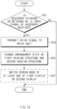
- the memory stores instructions that, when executed, cause the processor to determine occurrence of a first event and change the arrangement state by transmitting at least
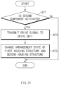
- a method for changing a form of a foldable electronic device includes determining occurrence of a first event, transmitting at least one of a plurality of drive signals to a drive unit depending on the first event, and changing, by a hinge structure, an arrangement state of a first housing structure and a second housing structure disposed on opposite sides of the hinge structure by rotating depending on operation of the drive unit according to the plurality of drive signals.
- a first display folded about a folding area is disposed on a first surface of the first housing structure and a first surface of the second housing structure, and a second display is disposed on at least one of a second surface of the first housing structure or a second surface of the second housing structure.
- the display of the foldable electronic device may be folded with a set angle depending on an event occurring in the electronic device.
- a user interface with high usability may be provided to a user depending on an event occurring in the electronic device.
- the disclosure may provide various effects that are directly or indirectly recognized.
- FIG. 1 is a view illustrating a foldable electronic device according to an embodiment.
- the foldable electronic device 100 may include a first housing structure 110A, a second housing structure 110B, a first display 130, a second display 135, a hinge structure 150, a drive unit 155, a processor 170, and a memory 190.
- the first housing structure 110A may accommodate the first display 130.
- a recess for accommodating a portion of the first display 130 may be formed on a first surface (e.g., a front surface) of the first housing structure 110A.
- the first housing structure 110A may additionally accommodate the second display 135.
- a recess for accommodating the second display 135 may be formed on a second surface (e.g., a rear surface) of the first housing structure 110A.
- at least a portion of the first housing structure 110A may be formed of a metallic or non-metallic material having a stiffness of a set magnitude to support the first display 130 (or, the first display 130 and the second display 135).
- the second housing structure 110B may accommodate a portion of the first display 130.
- a recess for accommodating the first display 130 may be formed on a first surface (e.g., a front surface) of the second housing structure 110B.
- the second housing structure 110B may additionally accommodate the second display 135.
- a recess for accommodating the second display 135 may be formed on a second surface (e.g., a rear surface) of the second housing structure 110B.
- at least a portion of the second housing structure 110B may be formed of a metallic or non-metallic material having a stiffness of a set magnitude to support the first display 130 (or, the first display 130 and the second display 135).
- the second housing structure 110B may be disposed on an opposite side of the foldable electronic device 100 with respect to the folding axis A.
- the second housing structure 110B may be connected with the first housing structure 110A with the folding axis A therebetween.
- the remaining portion other than the portion of the first display 130 disposed on the first surface of the first housing structure 110A may be disposed on the first surface (e.g., the front surface) of the second housing structure 110B.
- the second housing structure 110B may be disposed to be symmetric to the first housing structure 110A with respect to the folding axis A.
- the second display 135 may provide another user interface through a front surface thereof (e.g., a screen display area).
- a front surface thereof e.g., a screen display area
- an application program e.g., video call
- a first screen e.g., a full screen
- a second screen e.g., a screen simplified when compared to the first screen
- the second display 135 when the second display 135 is formed of a flexible (or, foldable) display having a size that is the same as or similar to that of the first display 130, the second display 135 may be folded such that the second surface (e.g., the rear surface) of the first housing structure 110A and the second surface (e.g., the rear surface) of the second housing structure 110B face each other.
- the second surface e.g., the rear surface
- the hinge structure 150 may be disposed between the first housing structure 110A and the second housing structure 110B.
- the first housing structure 110A may be connected to one side of the hinge structure 150
- the second housing structure 110B may be connected to an opposite side of the hinge structure 150.
- a plurality of hinge structures 150 may be disposed along the folding axis A.
- the hinge structures 150 may be disposed on an upper side and a lower side of the folding axis A and at the center of the folding axis A.
- the drive unit 155 when operating depending on at least one drive signal, may provide torque to the hinge structure 150. According to various embodiments, the drive unit 155 may rotate the hinge structure 150 to set an angle between the first housing structure 110A and the second housing structure 110B. According to various embodiments, the drive unit 155 may include a motor.
- the drive unit 155 may be disposed parallel to the folding axis A of the hinge structure 150.
- the drive unit 155 may be disposed between the first housing structure 110A and the second housing structure 110B.
- as many drive units 155 as hinge structures 150 may be provided.
- drive shafts e.g., motor shafts
- the drive unit 155 may be connected to only the hinge structure 150 disposed at the center of the folding axis A. In this case, the drive unit 155 may rotate the hinge structure 150 disposed at the center of the folding axis A to rotate hinge structures 150 disposed away from the center of the folding axis A.
- the processor 170 may transmit the drive signal to the drive unit 155 depending on the first event corresponding to an input signal (e.g., long press or double tap) of the accessory detached from the foldable electronic device 100. For example, when the input signal of the accessory is received in excess of a set period of time, the processor 170 may determine that the first event occurs and may transmit, to the drive unit 155, the drive signal (e.g., a signal that causes the foldable electronic device 100 to rotate to an intermediate state) that corresponds to the first event.
- the drive signal e.g., a signal that causes the foldable electronic device 100 to rotate to an intermediate state
- the processor 170 may transmit, to the drive unit 155, the drive signal (e.g., a signal that causes the foldable electronic device 100 to rotate to a flat state) that corresponds to the input signal of the first component.
- the processor 170 may transmit, to the drive unit 155, the drive signal (e.g., a signal that causes the foldable electronic device 100 to rotate to a flat state) that corresponds to the input signal of the first component.
- the processor 170 may transmit the drive signal to the drive unit 155 depending on the first event corresponding to a voice input signal from the outside (e.g., the user). For example, the processor 170 may change an arrangement state (e.g., a flat state, an intermediate state, or a folded state) of the foldable electronic device 100 to a different arrangement state (e.g., a flat state, an intermediate state, or a folded state) depending on a command (or, data) for the first event that is received through an input device (e.g., a microphone).
- an arrangement state e.g., a flat state, an intermediate state, or a folded state
- a command or, data
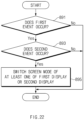
- the processor 170 may switch at least one of the first display 130 or the second display 135 to a set screen mode depending on a second event according to a drive signal for changing an arrangement state (e.g., a flat state, an intermediate state, or a folded state) of the foldable electronic device 100.
- an arrangement state e.g., a flat state, an intermediate state, or a folded state
- the processor 170 may switch the screen of the display to a second screen mode (e.g., a table mode) in which the screen of the second display 135 is displayed on the first display 130.
- a second screen mode e.g., a table mode
- the same screen or different screens may be displayed on the first display area and the second display area disposed on the opposite sides of the folding area 130C.
- the processor 170 may switch the screen of the display to a third screen mode (e.g., a phone mode) in which the screen of the first display 130 is displayed on the second display 135.
- a third screen mode e.g., a phone mode
- the processor 170 may switch at least one of the first display 130 or the second display 135 to the first screen mode to the third screen mode such that screen transition is seamless.
- the processor 170 may generate a drive signal depending on an arrangement state (e.g., a flat state, an intermediate state, or a folded state) of the first housing structure 110A and the second housing structure 110B. For example, when the angle between the first housing structure 110A and the second housing structure 110B is less than 10 degrees, the processor 170 may generate at least one of the first drive signal (e.g., a signal that causes the foldable electronic device 100 to rotate to a flat state) or the second drive signal (e.g., a signal that causes the foldable electronic device 100 to rotate to an intermediate state).
- the first drive signal e.g., a signal that causes the foldable electronic device 100 to rotate to a flat state
- the second drive signal e.g., a signal that causes the foldable electronic device 100 to rotate to an intermediate state
- the processor 170 may generate at least one of the first drive signal (e.g., a signal that causes the foldable electronic device 100 to rotate to a flat state) or the third drive signal (e.g., a signal that causes the foldable electronic device 100 to rotate to a folded state).
- the first drive signal e.g., a signal that causes the foldable electronic device 100 to rotate to a flat state
- the third drive signal e.g., a signal that causes the foldable electronic device 100 to rotate to a folded state
- the processor 170 may generate at least one of the second drive signal (e.g., a signal that causes the foldable electronic device 100 to rotate to an intermediate state) or the third drive signal (e.g., a signal that causes the foldable electronic device 100 to rotate to a folded state).
- the second drive signal e.g., a signal that causes the foldable electronic device 100 to rotate to an intermediate state
- the third drive signal e.g., a signal that causes the foldable electronic device 100 to rotate to a folded state
- the processor 170 may determine an arrangement state (e.g., a flat state, an intermediate state, or a folded state) of the first housing structure 110A and the second housing structure 110B depending on angle information obtained from a sensor.
- an arrangement state e.g., a flat state, an intermediate state, or a folded state
- the processor 170 may generate a drive signal depending on a motion state corresponding to motion of at least one of the first housing structure 110A or the second housing structure 110B. For example, when the foldable electronic device 100 is placed on a table and there is no movement within a range, the processor 170 may generate a drive signal depending on an arrangement state of the first housing structure 110A and the second housing structure 110B. In another example, when the foldable electronic device 100 is placed on a table and the first housing structure 110A rotates about the hinge structure 150, the processor 170 may not generate a drive signal.
- the processor 170 may determine a motion state (e.g., stop or movement) of the first housing structure 110A and the second housing structure 110B depending on motion information obtained from a sensor.
- a motion state e.g., stop or movement
- the memory 190 may be operationally connected with the processor 170.
- the memory 190 may store various types of data (e.g., instructions) used by the processor 170.
- the various types of data stored in the memory 190 may be transmitted to the processor 170 by a request of the processor 170, or may be extracted by access of the processor 170 and may be executed in the processor 170.
- some components e.g., a battery
- the foldable electronic device 100 may maintain the center of gravity even when the first housing structure 110A rotates about the hinge structure 150.
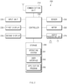
- FIG. 2 is a block diagram of a foldable electronic device according to an embodiment.
- the foldable electronic device 200 may include a communication unit 210, an input unit 220, a first display 230, a second display 235, a controller 240, a sensor 250, a motor 260, an audio processing unit 270, and storage 280.
- the communication unit 210 may be operationally connected with at least some components (e.g., an accessory) of the foldable electronic device 200.
- the communication unit 210 may establish communication channels between the at least some components (e.g., the accessory) of the foldable electronic device 200 and the controller 240.
- the communication unit 210 may additionally establish a communication channel between the foldable electronic device 200 and another electronic device (e.g., a smart phone).
- the input unit 220 may receive various signals input from the outside (e.g., a user).
- the input unit 220 may receive input signals (e.g., long press and double tap) from the at least some components (e.g., the accessory) of the electronic device 200 through the communication unit 210.
- the input unit 220 may receive an input signal (e.g., touch) that is input through at least one of the first display 230 or the second display 235.
- the input unit 220 may receive an input signal (e.g., gesture) that is input through the sensor 250.
- the input unit 220 may receive an input signal (e.g., voice) that is input through the audio processing unit 270.
- the first display 230 may provide a user interface (e.g., a user interface 283) to transmit an input signal (e.g., touch) to the input unit 220.
- the first display 230 may provide a user interface including components corresponding to various application programs (e.g., video call).
- the components may include an application program that generates a drive signal (e.g., a signal that causes the motor 260 to operate).
- the components may include, for example, an application program, the execution screen of which is supported on one of the first display 230 or the second display 235.
- the second display 235 may provide a user interface (e.g., the user interface 283) that is different from (or, the same as) that of the first display 230.
- the controller 240 may generate a drive signal depending on various events (e.g., the first event disclosed in the description of FIG. 1 ) that are received through the input unit 220.
- the controller 240 may transmit the drive signal to the motor 260.
- the controller 240 may switch a screen of at least one of the first display 230 or the second display 235 to a set screen mode (e.g., the tablet mode, the table mode, or the phone mode disclosed in the description of FIG. 1 ) depending an additional event (e.g., the second event disclosed in the description of FIG. 1 ).
- the controller 240 may generate the drive signal using at least one of angle information or motion information obtained through the sensor 250. For example, even though sensing occurrence of an event through the input unit 220, the controller 240 may not generate the drive signal when at least one of the angle information or the motion information is not satisfied. In this case, the controller 240 may switch the screen of at least one of the first display 230 or the second display 235 to the set screen mode depending on a forced input from the outside (e.g., the user) (e.g., an operation in which the first display 230 and the second display 235 are unfolded or folded by an external force).
- a forced input from the outside e.g., the user
- the controller 240 may change an arrangement state (e.g., a flat state, an intermediate state, or a folded state) of at least some components (e.g., the first housing structure 110A and the second housing structure 110B of FIG. 1 ) of the foldable electronic device 200 depending on an external signal (e.g., the user's motion) that is input through the sensor 250.
- an arrangement state e.g., a flat state, an intermediate state, or a folded state
- an external signal e.g., the user's motion
- the sensor 250 may detect at least one of angle information or motion information.
- the sensor 250 may detect the angle information by sensing the angle between at least some components (e.g., the first housing structure 110A and the second housing structure 110B of FIG. 1 ) of the foldable electronic device 200.
- the sensor 250 may detect the motion information by sensing motion (e.g., stop or movement) of the foldable electronic device 200.
- the sensor 250 may transmit at least one of the angle information or the motion information to the controller 240 such that the controller 240 determines a condition under which a drive signal is generated.
- the sensor 250 may detect an input signal by the user (e.g., the user's motion).
- the senor 250 may transmit the input signal by the user to the controller 240 such that a drive signal is generated.
- the sensor 250 may include at least one of an angle sensor, a gyro sensor, an acceleration sensor, an image sensor, a proximity sensor, an illuminance sensor, a grip sensor, or a current detection sensor.
- the motor 260 may operate (e.g., rotate by converting electrical energy into mechanical energy) depending on a drive signal transmitted from the controller 240.
- the motor 260 may provide torque to at least some components (e.g., the first housing structure 110A and the second housing structure 110B of FIG. 1 ) of the foldable electronic device 200.
- the motor 260 may include a drive shaft (e.g., a motor shaft).
- the drive shaft may be connected to at least one hinge structure (e.g., the hinge structure 150 of FIG. 1 ).
- the audio processing unit 270 may detect a voice input signal from the outside (e.g., the user). For example, the audio processing unit 270 may receive the voice input signal through an input device. For example, the audio processing unit 270 may transmit the voice input signal to the controller 240 such that a drive signal is generated. According to various embodiments, the audio processing unit 270 may obtain sound through an input device (e.g., a microphone), or may output sound through a sound output device (e.g., a speaker).
- an input device e.g., a microphone
- a sound output device e.g., a speaker
- the storage 280 may include an operating system 281, the user interface 283, and an application program 285.
- the operating system 281 may provide, to the first display 230 and the second display 235, an underlying environment for execution of the application program 285.
- the application program 285 may be a program for generating a drive signal that is transmitted from the controller 240 to the motor 260.
- the application program 285 may be a program, the execution screen of which is supported on one of the first display 230 or the second display 235.
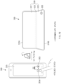
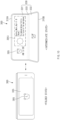
- an arrangement state of a first housing structure 310A and a second housing structure 310B of the foldable electronic device 300 may be changed depending on whether an accessory 301 (e.g., a stylus pen) is attached to or detached from the foldable electronic device 300.
- an accessory 301 e.g., a stylus pen
- the foldable electronic device 300 may be changed from a folded state to a flat state when the accessory 301 is detached from the second housing structure 310B (or, the first housing structure 310A).
- first surfaces e.g., front surfaces
- first housing structure 310A and the second housing structure 310B of the foldable electronic device 300 may be disposed to face each other.
- a second display 335 e.g., the second display 135 of FIG. 1
- a second surface e.g., a rear surface
- the foldable electronic device 300 may determine the detachment of the accessory 301 to be a first event and may generate a drive signal for a drive unit (e.g., the drive unit 155 of FIG. 1 ) (e.g., a motor). Accordingly, when a hinge structure (e.g., the hinge structure 150 of FIG. 1 ) is rotated through a set angle (e.g., 180 degrees) by the drive signal for the first event, the foldable electronic device 300 may be changed to the flat state in which the first housing structure 310A and the second housing structure 310B face the same direction. At this time, a first display 330 (e.g., the first display 130 of FIG. 1 ) of the foldable electronic device 300 may be exposed in the direction in which the first surfaces (e.g., the front surfaces) are located.
- a drive unit e.g., the drive unit 155 of FIG. 1
- a motor e.g., a motor
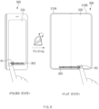
- FIG. 4 is a view illustrating a change of state of the foldable electronic device according to various embodiments.
- an arrangement state of the first housing structure 310A and the second housing structure 310B of the foldable electronic device 300 may be changed depending on an input signal (e.g., long press or double tap) of the accessory 301 (e.g., a stylus pen) detached from the foldable electronic device 300.
- an input signal e.g., long press or double tap
- the accessory 301 e.g., a stylus pen
- the foldable electronic device 300 may be changed from a folded state to a flat state when the input signal is received from the accessory 301 detached from the second housing structure 310B (or, the first housing structure 310A).
- the first surfaces (e.g., the front surfaces) of the first housing structure 310A and the second housing structure 310B of the foldable electronic device 300 may be disposed to face each other.
- the foldable electronic device 300 may determine the input signal to be a first event and may generate a drive signal for the drive unit (e.g., the drive unit 155 of FIG. 1 ) (e.g., a motor).
- the drive unit e.g., the drive unit 155 of FIG. 1
- the foldable electronic device 300 may be changed to the flat state in which the first housing structure 310A and the second housing structure 310B face the same direction.
- the foldable electronic device 300 may form a communication interface with the accessory 310 detached from the second housing structure 310B.
- a first short-range communication module may be disposed in the foldable electronic device 300.
- a second short-range communication module for communication with the first short-range communication module may be disposed in the accessory 301.
- the foldable electronic device 300 may display the first component 303 on the screen.
- the first surfaces e.g., the front surfaces
- the foldable electronic device 300 may display the first component 303 when the application program 302 (e.g., an SMS App) is activated.
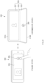
- the foldable electronic device 300 may determine the activation of the first component 303 depending on the activation of the application program 302 (e.g., an SMS App) to be a first event and may generate a drive signal for the drive unit (e.g., the drive unit 155 of FIG. 1 ) (e.g., a motor). Accordingly, when the hinge structure (e.g., the hinge structure 150 of FIG. 1 ) is rotated through a set angle (e.g., 180 degrees) by the drive signal for the first event, the foldable electronic device 300 may be changed to a flat state in which the first housing structure 310A and the second housing structure 310B face the same direction.
- the application program 302 e.g., an SMS App
- FIG. 7A is a view illustrating a change of state of the foldable electronic device according to various embodiments.
- FIG. 7B is a view illustrating a change of state of the foldable electronic device according to various embodiments.
- an arrangement state of the first housing structure 310A and the second housing structure 310B of the foldable electronic device 300 may be changed depending on activation of a first component 303 according to an input signal of the first component 303.
- the foldable electronic device 300 may be changed from a folded state to a flat state depending on a first distance D1 that the input signal of the first component 303 moves.
- the first surfaces e.g., the front surfaces
- the foldable electronic device 300 may determine the movement of the input signal to be a first event and may generate a drive signal for the drive unit (e.g., the drive unit 155 of FIG. 1 ) (e.g., a motor).
- the foldable electronic device 300 may be changed to the flat state in which the first housing structure 310A and the second housing structure 310B face the same direction.
- the foldable electronic device 300 may be changed from a folded state to an intermediate state depending on a second distance D2 that the input signal of the first component 303 moves.
- the first surfaces e.g., the front surfaces
- the foldable electronic device 300 may determine the movement of the input signal to be a first event and may generate a drive signal for the drive unit (e.g., the drive unit 155 of FIG. 1 ) (e.g., a motor).
- the foldable electronic device 300 may be changed to the intermediate state in which the first housing structure 310A and the second housing structure 310B face directions crossing each other.
- a folding area 333 disposed between a first display area 331 and a second display area 332 of the first display 330 of the foldable electronic device 300 may be folded with a set angle (e.g., 135 degrees).
- the foldable electronic device 300 may determine the change of state to be a second event. For example, a screen mode of the foldable electronic device 300 may be switched from a phone mode corresponding to the folded state to a table mode corresponding to the intermediate state depending on the second event according to the screen transition of the first display 330 and the second display 335.
- FIG. 8 is a view illustrating a change of state of the foldable electronic device according to various embodiments.
- an arrangement state of the first housing structure 310A and the second housing structure 310B of the foldable electronic device 300 may be changed depending on activation of a first component 303 according to an input signal of the first component 303.
- the foldable electronic device 300 may be changed from a folded state (or, a flat state) to the flat state (or, the folded state) depending on a direction R1 or R2 in which the input signal of the first component 303 moves.
- the first surfaces e.g., the front surfaces
- the foldable electronic device 300 may determine the generation of the input signal to be a first event and may generate a drive signal for the drive unit (e.g., the drive unit 155 of FIG.
- the foldable electronic device 300 may be changed to the flat state in which the first housing structure 310A and the second housing structure 310B face the same direction.
- the hinge structure e.g., the hinge structure 150 of FIG.
- the foldable electronic device 300 may be changed to the folded state in which the first housing structure 310A and the second housing structure 310B face each other.
- FIG. 9 is a view illustrating a change of state of the foldable electronic device according to various embodiments.
- an arrangement state of the first housing structure 310A and the second housing structure 310B of the foldable electronic device 300 may be changed depending on activation of a second component 305 on the screen of the first display 330 and the second display 335.
- the second component 305 may be, for example, an application program, the execution screen of which is supported on one of the first display 330 or the second display 335.
- the second component 305 when executed, may automatically change the arrangement state of the first housing structure 310A and the second housing structure 310B even when a separate component for changing the arrangement state of the first housing structure 310A and the second housing structure 310B is not executed.
- the foldable electronic device 300 may be changed from a folded state to an intermediate state (or, a flat state) when the second component 305 (e.g., an application program supporting a video call function) on the screen of the second display 335 (or, the first display 330) is activated.
- the second component 305 e.g., an application program supporting a video call function
- the first surfaces e.g., the front surfaces
- the first housing structure 310A and the second housing structure 310B of the foldable electronic device 300 may be disposed to face each other.
- the foldable electronic device 300 may determine the activation of the second component 305 to be a first event and may generate a drive signal for the drive unit (e.g., the drive unit 155 of FIG. 1 ) (e.g., a motor). Accordingly, when the hinge structure (e.g., the hinge structure 150 of FIG. 1 ) is rotated through a set angle (e.g., 135 degrees) by the drive signal for the first event, the foldable electronic device 300 may be changed to the intermediate state in which the first housing structure 310A and the second housing structure 310B face directions crossing each other.
- a drive signal for the drive unit e.g., the drive unit 155 of FIG. 1
- the hinge structure e.g., the hinge structure 150 of FIG. 1
- the foldable electronic device 300 may be changed to the intermediate state in which the first housing structure 310A and the second housing structure 310B face directions crossing each other.
- the folding area 333 disposed between the first display area 331 and the second display area 332 of the first display 330 of the foldable electronic device 300 may be folded with a set angle (e.g., 135 degrees).
- a set angle e.g. 135 degrees
- the second component 305 is changed from an active state (e.g., running) to an inactive state (e.g., end of running) and the hinge structure (e.g., the hinge structure 150 of FIG. 1 ) is rotated through a set angle (e.g., less than 10 degrees) by the drive signal depending on the first event
- the foldable electronic device 300 may be changed to the folded state in which the first housing structure 310A and the second housing structure 310B face each other.
- the foldable electronic device 300 may display a screen (e.g., the face of a counterpart performing a video call) depending on the activation of the second component 305 on the screen of the second display 305. Furthermore, when changed from the folded state to the intermediate state (or, the flat state) depending on the activation of the second component, the screen displayed on the screen of the second display 335 may be displayed on the screen of the first display 330.
- the foldable electronic device 300 may recognize an object (e.g., the face of a user performing a video call) that faces the screen depending on the activation of the second component 305 and may adjust the angle through which the hinge structure (e.g., the hinge structure 150 of FIG. 1 ) rotates.
- the foldable electronic device 300 may recognize the face of the user through a sensor module (e.g., a camera module).
- the sensor module may be disposed on the first surface of the first housing structure 310A (or, the second housing structure 310B).
- FIG. 10 is a view illustrating a change of state of the foldable electronic device according to various embodiments.
- an arrangement state of the first housing structure 310A and the second housing structure 310B of the foldable electronic device 300 may be changed depending on activation of a second component 305 on the screen of the first display 330 and the second display 335.
- the second component 305 may be, for example, an application program that is automatically activated depending on a set condition (e.g., time).
- the second component 305 when executed, may automatically change the arrangement state of the first housing structure 310A and the second housing structure 310B even when a separate component for changing the arrangement state of the first housing structure 310A and the second housing structure 310B is not executed.
- the foldable electronic device 300 may be changed from a folded state to an intermediate state (or, a flat state) when the second component 305 (e.g., an application program supporting an alarm function) on the screen of the second display 335 (or, the first display 330) is activated.
- the second component 305 e.g., an application program supporting an alarm function
- the first surfaces e.g., the front surfaces
- the first housing structure 310A and the second housing structure 310B of the foldable electronic device 300 may be disposed to face each other.
- the foldable electronic device 300 may determine the activation of the second component 305 to be a first event and may generate a drive signal for the drive unit (e.g., the drive unit 155 of FIG. 1 ) (e.g., a motor). Accordingly, when the hinge structure (e.g., the hinge structure 150 of FIG. 1 ) is rotated through a set angle (e.g., 135 degrees) by the drive signal for the first event, the foldable electronic device 300 may be changed to the intermediate state in which the first housing structure 310A and the second housing structure 310B face directions crossing each other. At this time, additional information 305i (e.g., weather and news) depending on the execution of the second component 305 may be provided on the screen of the first display 330.
- the drive unit e.g., the drive unit 155 of FIG. 1
- the foldable electronic device 300 may be changed to the intermediate state in which the first housing structure 310A and the second housing structure 310B face directions crossing each other.
- additional information 305i
- FIG. 11 is a view illustrating a change of state of the foldable electronic device according to various embodiments.
- an arrangement state of the first housing structure 310A and the second housing structure 310B of the foldable electronic device 300 may be changed depending on activation of a second component 305 on the screen of the first display 330 and the second display 335.
- the second component 305 may be an application program, the execution screen of which is supported on one of the first display 330 or the second display 335.
- the foldable electronic device 300 may be changed from a folded state to a flat state (or, an intermediate state) when the second component 305 (e.g., an application program supporting a digitizer function) on the screen of the second display 335 (or, the first display 330) is activated.
- the foldable electronic device 300 may execute a digitizer function only through the first display 330.
- an accessory e.g., a stylus pen
- the first surfaces e.g., the front surfaces
- the first housing structure 310A and the second housing structure 310B of the foldable electronic device 300 may be disposed to face each other.
- the foldable electronic device 300 may determine an external input (e.g., a user input) depending on the activation of the second component 305 to be a first event and may generate a drive signal for the drive unit (e.g., the drive unit 155 of FIG. 1 ) (e.g., a motor). Accordingly, when the hinge structure (e.g., the hinge structure 150 of FIG. 1 ) is rotated through a set angle (e.g., 180 degrees) by the drive signal for the first event, the foldable electronic device 300 may be changed to the flat state in which the first housing structure 310A and the second housing structure 310B face the same direction.
- a set angle e.g. 180 degrees
- the foldable electronic device 300 may be changed to the folded state in which the first housing structure 310A and the second housing structure 310B face each other.
- the foldable electronic device 300 may allow the arrangement state of the first housing structure 310A and the second housing structure 310B to be selectively changed depending on the external input (e.g., the user input).
- the foldable electronic device 300 may receive the external input through a selection component 305s.
- the selection component 305s may be a user interface for selecting an arrangement state (e.g., one of a folded state, an intermediate state, and a flat state) of the first housing structure 310A and the second housing structure 310B.
- FIG. 12 is a view illustrating a change of state of the foldable electronic device according to various embodiments.
- an arrangement state of the first housing structure 310A and the second housing structure 310B of the foldable electronic device 300 may be changed depending on activation of a second component 305 on the screen of the first display 330 and the second display 335.
- the foldable electronic device 300 may be changed from a folded state to a flat state (or, an intermediate state) depending on an external input (e.g., a user input) when the second component 305 (e.g., an application program supporting image acquisition) on the screen of the second display 335 (or, the first display 330) is activated.
- the second component 305 e.g., an application program supporting image acquisition
- the first surfaces (e.g., the front surfaces) of the first housing structure 310A and the second housing structure 310B of the foldable electronic device 300 may be disposed to face each other.
- the foldable electronic device 300 may determine an external input (e.g., a user input) (e.g., a panoramic shot command) depending on the activation of the second component 305 to be a first event and may generate a drive signal for the drive unit (e.g., the drive unit 155 of FIG. 1 ) (e.g., a motor). Accordingly, when the hinge structure (e.g., the hinge structure 150 of FIG. 1 ) is rotated through a set angle (e.g., 180 degrees) by the drive signal for the first event, the foldable electronic device 300 may be changed to the flat state in which the first housing structure 310A and the second housing structure 310B face the same direction.
- an external input e.g., a user input
- a drive unit e.g., the drive unit 155 of FIG. 1
- the foldable electronic device 300 may be changed to the flat state in which the first housing structure 310A and the second housing structure 310B face the same direction.
- the direction that at least some components (e.g., a lens) of a camera module 305c face may be changed as the arrangement state of the first housing structure 310A and the second housing structure 310B of the foldable electronic device 300 is changed.
- the foldable electronic device 300 may be repeatedly unfolded with a certain angle (e.g., 5 degrees) and stopped depending on a function (e.g., a panoramic shot) of an application program (e.g., an application program supporting image acquisition).
- FIG. 13A is a view illustrating a change of state of the foldable electronic device according to various embodiments.
- FIG. 13B is a view illustrating a change of state of the foldable electronic device according to various embodiments.
- FIG. 13C is a view illustrating a change of state of the foldable electronic device according to various embodiments.
- an arrangement state of the first housing structure 110A and the second housing structure 110B of the foldable electronic device 330 may be changed depending on a key input signal 307 for changing the first display 330 or the second display 135 from a locked state to an unlocked state.
- the foldable electronic device 300 may be changed from a folded state to a flat state when the key input signal 307 (e.g., biometric information of a user, a pattern, or a movement direction) is input to the second display 335.
- the key input signal 307 e.g., biometric information of a user, a pattern, or a movement direction
- the first surfaces e.g., the front surfaces
- the foldable electronic device 300 may determine the key input signal 307 to be a first event and may generate a drive signal for the drive unit (e.g., the drive unit 155 of FIG. 1 ) (e.g., a motor).
- the foldable electronic device 300 may be changed to the flat state in which the first housing structure 310A and the second housing structure 310B face the same direction.
- FIG. 14 is a view illustrating a flat state of a foldable electronic device according to an embodiment.
- FIG. 15 is a view illustrating a folded state of the foldable electronic device according to an embodiment.
- the electronic device 10 may include a foldable housing 500, a hinge cover 530 that covers a foldable portion of the foldable housing, and a flexible or foldable display 105 (hereinafter, abbreviated to the "display” 105) that is disposed in a space formed by the foldable housing 500.
- a surface on which the display 105 is disposed is defined as a first surface or a front surface of the electronic device 10.
- a surface facing away from the front surface is defined as a second surface or a rear surface of the electronic device 10.
- surfaces surrounding a space between the front surface and the rear surface are defined as third surface or side surfaces of the electronic device 10.
- the foldable housing 500 may include a first housing structure 510, a second housing structure 520 including a sensor area 524, a first back cover 580, and a second back cover 590.
- the foldable housing 500 of the electronic device 10 is not limited to the form and coupling illustrated in FIGS. 14 and 15 and may be implemented by a combination and/or coupling of other shapes or components.
- the first housing structure 510 and the first back cover 580 may be integrally formed with each other, and the second housing structure 520 and the second back cover 590 may be integrally formed with each other.
- the first housing structure 510 and the second housing structure 520 may be disposed on opposite sides of a folding axis A and may have shapes entirely symmetric to each other with respect to the folding axis A.
- the angle or distance between the first housing structure 510 and the second housing structure 520 may vary depending on whether the electronic device 10 is in a flat state, a folded state, or an intermediate state.
- the second housing structure 520 may additionally include the sensor area 524 in which various sensors are disposed.
- the first housing structure 510 and the second housing structure 520 may have mutually symmetrical shapes in the other areas.
- the first housing structure 510 and the second housing structure 520 may form a recess in which the display 105 is accommodated.
- the recess may have two or more different widths in a direction perpendicular to the folding axis A.
- the recess may have (1) a first width w1 between a first portion 510a of the first housing structure 510 that is parallel to the folding axis A and a first portion 520a of the second housing structure 520 that is formed on the periphery of the sensor area 524 and (2) a second width w2 between a second portion 510b of the first housing structure 510 and a second portion 520b of the second housing structure 520 that does not correspond to the sensor area 524 and that is parallel to the folding axis A.
- the second width w2 may be greater than the first width w1.
- the first portion 510a of the first housing structure 510 and the first portion 520a of the second housing structure 520 that have mutually asymmetrical shapes may form the first width w1 of the recess
- the second portion 510b of the first housing structure 510 and the second portion 520b of the second housing structure 520 that have mutually symmetrical shapes may form the second width w2 of the recess.
- the first portion 520a and the second portion 520b of the second housing structure 520 may have different distances from the folding axis A.
- the width of the recess is not limited to the illustrated example.
- the recess may have a plurality of widths depending on the form of the sensor area 524 or the asymmetrical portions of the first housing structure 510 and the second housing structure 520.
- At least part of the first housing structure 510 and at least part of the second housing structure 520 may be formed of a metallic or non-metallic material having a stiffness of a selected magnitude to support the display 105.
- the sensor area 524 may be formed to have a predetermined area adjacent to one corner of the second housing structure 520.
- the arrangement, shape, and size of the sensor area 524 are not limited to the illustrated example.
- the sensor area 524 may be provided in another corner of the second housing structure 520 or in any area between an upper corner and a lower corner of the second housing structure 520.
- components embedded in the electronic device 10 for performing various functions may be exposed on the front surface of the electronic device 10 through the sensor area 524 or through one or more openings formed in the sensor area 524.
- the components may include various types of sensors.
- the sensors may include, for example, at least one of a front camera, a receiver, or a proximity sensor.
- the first back cover 580 may be disposed on one side of the folding axis on the rear surface of the electronic device.
- the first back cover 580 may have a substantially rectangular periphery, and the periphery may be surrounded by the first housing structure 510.
- the second back cover 590 may be disposed on an opposite side of the folding axis on the rear surface of the electronic device, and the periphery of the second back cover 590 may be surrounded by the second housing structure 520.
- the first back cover 580 and the second back cover 590 may have substantially symmetrical shapes with respect to the folding axis A. However, the first back cover 580 and the second back cover 590 do not necessarily have to have mutually symmetrical shapes.
- the electronic device 10 may include the first back cover 580 and the second back cover 590 in various shapes.
- the first back cover 580 may be integrally formed with the first housing structure 510
- the second back cover 590 may be integrally formed with the second housing structure 520.
- the first back cover 580, the second back cover 590, the first housing structure 510, and the second housing structure 520 may form a space in which various components (e.g., a printed circuit board or a battery) of the electronic device 10 are disposed.
- one or more components may be disposed, or visually exposed, on the rear surface of the electronic device 10.
- at least part of a sub-display 535 may be visually exposed through a first rear area 582 of the first back cover 580.
- one or more components or sensors may be visually exposed through a second rear area 592 of the second back cover 590.
- the sensors may include a proximity sensor and/or a rear camera.
- the hinge cover 530 may be disposed between the first housing structure 510 and the second housing structure 520 and may be configured to hide an internal component (e.g., a hinge structure). In an embodiment, the hinge cover 530 may be hidden by part of the first housing structure 510 and part of the second housing structure 520, or may be exposed to the outside, depending on a state (a flat state or a folded state) of the electronic device 10.
- an internal component e.g., a hinge structure
- the hinge cover 530 may be hidden by part of the first housing structure 510 and part of the second housing structure 520, or may be exposed to the outside, depending on a state (a flat state or a folded state) of the electronic device 10.
- the display 105 may be disposed in the space formed by the foldable housing 500.
- the display 105 may be seated in the recess formed by the foldable housing 500 and may form most of the front surface of the electronic device 10.
- the front surface of the electronic device 10 may include the display 105, and a partial area of the first housing structure 510 and a partial area of the second housing structure 520 that are adjacent to the display 105.
- the rear surface of the electronic device 10 may include the first back cover 580, a partial area of the first housing structure 510 that is adjacent to the first back cover 580, the second back cover 590, and a partial area of the second housing structure 520 that is adjacent to the second back cover 590.
- the division of the display 105 into the areas illustrated in FIG. 14 is illustrative, and the display 105 may be divided into a plurality of areas (e.g., four or more areas, or two areas) depending on the structure or function of the display 105.
- the areas of the display 105 may be divided from each other by the folding area 103 or the folding axis A that extends parallel to the y-axis.
- the display 105 may be divided into areas with respect to another folding area (e.g., a folding area parallel to the x-axis) or another folding axis (e.g., a folding axis parallel to the x-axis).
- the first area 101 and the second area 102 may have shapes entirely symmetric to each other with respect to the folding area 103.
- the second area 102 may include a notch that is cut depending on the presence of the sensor area 524, and in the other area, the second area 102 may have a shape symmetric to the shape of the first area 101.
- the first area 101 and the second area 102 may include portions having mutually symmetrical shapes and portions having mutually asymmetrical shapes.
- the first housing structure 510 and the second housing structure 520 may be disposed to face the same direction while forming an angle of 180 degrees therebetween.
- a surface of the first area 101 and a surface of the second area 102 of the display 105 may face the same direction (e.g., the direction toward the front surface of the electronic device) while forming an angle of 180 degrees.
- the folding area 103 may form the same plane as the first area 101 and the second area 102.
- the first housing structure 510 and the second housing structure 520 may be disposed to face each other.
- the surface of the first area 101 and the surface of the second area 102 of the display 105 may face each other while forming a narrow angle (e.g., an angle between 0 degrees and 10 degrees).
- At least part of the folding area 103 may be curved to have a predetermined curvature.
- the first housing structure 510 and the second housing structure 520 may form a certain angle therebetween.
- the surface of the first area 101 and the surface of the second area 102 of the display 105 may form an angle greater than that in the folded state and smaller than that in the flat state.
- At least part of the folding area 103 may be curved to have a predetermined curvature, and the curvature may be smaller than that in the folded state.
- the electronic device 10 may include a display unit 20, a bracket assembly 30, a circuit board 600, the first housing structure 510, the second housing structure 520, the first back cover 580, and the second back cover 590.
- the display unit 20 may be referred to as the display module or the display assembly.
- the display unit 20 may include the display 105 and one or more plates or layers 140 on which the display 105 is mounted.
- the plates 140 may be disposed between the display 105 and the bracket assembly 30.
- the display 105 may be disposed on at least part of one surface (e.g., an upper surface with respect to FIG. 16 ) of the plates 140.
- the plates 140 may be formed in a shape corresponding to the display 105. For example, partial areas of the plates 140 may be formed in a shape corresponding to a notch 104 of the display 105.
- the bracket assembly 30 may include a first bracket 410, a second bracket 420, a hinge structure disposed between the first bracket 410 and the second bracket 420, the hinge cover 530 that covers the hinge structure when viewed from the outside, and wiring members 430 (e.g., flexible printed circuits (FPCs)) across the first bracket 410 and the second bracket 420.
- wiring members 430 e.g., flexible printed circuits (FPCs)
- the bracket assembly 30 may be disposed between the plates 140 and the circuit board 600.
- the first bracket 410 may be disposed between the first area 101 of the display 105 and a first circuit board 610.
- the second bracket 420 may be disposed between the second area 102 of the display 105 and a second circuit board 620.
- the wiring members 430 and at least part of the hinge structure may be disposed inside the bracket assembly 30.
- the wiring members 430 may be disposed in a direction (e.g., the x-axis direction) across the first bracket 410 and the second bracket 420.
- the wiring members 430 may be disposed in a direction (e.g., the x-axis direction) perpendicular to a folding axis (e.g., the y-axis or the folding axis A of FIG. 14 ) of the folding area 103 of the electronic device 10.
- the circuit board 600 may include the first circuit board 610 disposed on one side of the first bracket 410 and the second circuit 620 disposed on one side of the second bracket 420.
- the first circuit board 610 and the second circuit board 620 may be disposed in a space formed by the bracket assembly 30, the first housing structure 510, the second housing structure 520, the first back cover 580, and the second back cover 590.
- Components for implementing various functions of the electronic device 10 may be mounted on the first circuit board 610 and the second circuit board 620.
- the first housing structure 510 and the second housing structure 520 may be assembled together so as to be coupled to opposite sides of the bracket assembly 30 in the state in which the display unit 20 is coupled to the bracket assembly 30. As will be described below, the first housing structure 510 and the second housing structure 520 may be coupled with the bracket assembly 30 by sliding on the opposite sides of the bracket assembly 30.
- the first housing structure 510 may include a first rotation support surface 512
- the second housing structure 520 may include a second rotation support surface 522 corresponding to the first rotation support surface 512.
- the first rotation support surface 512 and the second rotation support surface 522 may include a curved surface corresponding to the curved surface included in the hinge cover 530.
- the first rotation support surface 512 and the second rotation support surface 522 may cover the hinge cover 530 such that the hinge cover 530 is not exposed, or is minimally exposed, on the rear surface of the electronic device 10.
- the first rotation support surface 512 and the second rotation support surface 522 may rotate along the curved surface included in the hinge cover 530, and the hinge cover 530 may be exposed on the rear surface of the electronic device 10 to the maximum.
- Fig. 17 is a block diagram illustrating the program according to various embodiments.
- Fig. 17 is a block diagram 700 illustrating the program 740 according to various embodiments.
- the program 740 may include an operating system (OS) 742 to control one or more resources of the electronic device, middleware 744, or an application 746 executable in the OS 742.
- the OS 742 may include, for example, AndroidTM, iOSTM, WindowsTM, SymbianTM, TizenTM, or BadaTM.
- At least part of the program 740 may be pre-loaded on the electronic device during manufacture, or may be downloaded from or updated by an external electronic device (e.g., the electronic device 902 or 904, or the server 908 in Fig. 23 ) during use by a user.
- an external electronic device e.g., the electronic device 902 or 904, or the server 908 in Fig. 23
- the OS 742 may control management (e.g., allocating or deallocation) of one or more system resources (e.g., process, memory, or power source) of the electronic device.
- the OS 742 additionally or alternatively, may include one or more driver programs to drive other hardware devices of the electronic device, for example, the input device (e.g., the input device 950 in Fig. 23 ), the sound output device (e.g., the sound output device 955 in Fig. 23 ), the display device (e.g., the display device 960 in Fig. 23 ), the audio module (e.g., the audio module 970 in Fig. 23 ), the sensor module (e.g., the sensor module 976 in Fig.
- the input device e.g., the input device 950 in Fig. 23
- the sound output device e.g., the sound output device 955 in Fig. 23
- the display device e.g., the display device 960 in Fig. 23
- the audio module e.g.
- the interface e.g., the interface 977 in Fig. 23
- the haptic module e.g., the haptic module 979 in Fig. 23
- the camera module e.g., the camera module 980 in Fig. 23
- the power management module e.g., the power management module 988 in Fig. 23
- the battery e.g., the battery 989 in Fig. 23
- the communication module e.g., the communication module 990 in Fig. 23
- the subscriber identification module e.g., the subscriber identification module 996 in Fig. 23
- the antenna module e.g., the antenna module 997 in Fig. 23 ).
- the middleware 744 may provide various functions to the application 746 such that a function or information provided from one or more resources of the electronic device may be used by the application 746.
- the middleware 744 may include, for example, an application manager 701, a window manager 703, a multimedia manager 705, a resource manager 707, a power manager 709, a database manager 711, a package manager 713, a connectivity manager 715, a notification manager 717, a location manager 719, a graphic manager 721, a security manager 723, a telephony manager 725, or a voice recognition manager 727.
- the application manager 701 may manage the life cycle of the application 746.
- the window manager 703, for example, may manage one or more graphical user interface (GUI) resources that are used on a screen.
- GUI graphical user interface
- the multimedia manager 705, for example, may identify one or more formats to be used to play media files, and may encode or decode a corresponding one of the media files using a codec appropriate for a corresponding format selected from the one or more formats.
- the resource manager 707 for example, may manage the source code of the application 746 or a memory space of the memory.
- the power manager 709 for example, may manage the capacity, temperature, or power of the battery (e.g., the battery 989 in Fig.
- the power manager 709 may interwork with a basic input/output system (BIOS) (not shown) of the electronic device 901.
- BIOS basic input/output system
- the database manager 711 may generate, search, or change a database to be used by the application 746.
- the package manager 713 may manage installation or update of an application that is distributed in the form of a package file.
- the connectivity manager 715 may manage a wireless connection or a direct connection between the electronic device and the external electronic device.
- the notification manager 717 may provide a function to notify a user of an occurrence of a specified event (e.g., an incoming call, message, or alert).
- the location manager 719 may manage locational information on the electronic device.
- the graphic manager 721 for example, may manage one or more graphic effects to be offered to a user or a user interface related to the one or more graphic effects.
- the security manager 723, for example, may provide system security or user authentication.
- the telephony manager 725 for example, may manage a voice call function or a video call function provided by the electronic device.
- the voice recognition manager 727 may transmit a user's voice data to the server (e.g., the server 908 in Fig. 23 ), and receive, from the server (e.g., the server 908 in Fig. 23 ), a command corresponding to a function to be executed on the electronic device based at least in part on the voice data, or text data converted based at least in part on the voice data.
- the middleware 744 may dynamically delete some existing components or add new components.
- at least part of the middleware 744 may be included as part of the OS 742 or may be implemented as another software separate from the OS 742.
- the application 746 may include, for example, a home 751, dialer 753, short message service (SMS)/multimedia messaging service (MMS) 755, instant message (IM) 757, browser 759, camera 761, alarm 763, contact 765, voice recognition 767, email 769, calendar 771, media player 773, album 775, watch 777, health 779 (e.g., for measuring the degree of workout or biometric information, such as blood sugar), or environmental information 781 (e.g., for measuring air pressure, humidity, or temperature information) application.
- the application 746 may further include an information exchanging application (not shown) that is capable of supporting information exchange between the electronic device and the external electronic device.
- the information exchange application may include a notification relay application adapted to transfer designated information (e.g., a call, message, or alert) to the external electronic device or a device management application adapted to manage the external electronic device.
- the notification relay application may transfer notification information corresponding to an occurrence of a specified event (e.g., receipt of an email) at another application (e.g., the email application 769) of the electronic device to the external electronic device. Additionally or alternatively, the notification relay application may receive notification information from the external electronic device and provide the notification information to a user of the electronic device.
- the device management application may control the power (e.g., turn-on or turn-off) or the function (e.g., adjustment of brightness, resolution, or focus) of the external electronic device or some component thereof (e.g., a display device or a camera module of the external electronic device).
- the device management application additionally or alternatively, may support installation, delete, or update of an application running on the external electronic device.
- FIG. 18 is a flowchart illustrating a method of changing a state of a foldable electronic device according to various embodiments.
- a processor may change an arrangement state of a first housing structure (e.g., the first housing structure 110A of FIG. 1 ) and a second housing structure (e.g., the second housing structure 110B of FIG. 1 ) depending on a first event.
- a first housing structure e.g., the first housing structure 110A of FIG. 1
- a second housing structure e.g., the second housing structure 110B of FIG. 1
- the processor 170 may determine whether the first event occurs.
- the processor 170 may transmit a drive signal to a drive unit (e.g., the drive unit 155 of FIG. 1 ) depending on the first event.
- the drive signal may include at least one of a first drive signal for adjusting the amount of rotation of the drive unit (e.g., the first drive unit 155 of FIG. 1 ) such that the foldable electronic device 100 is in a flat state, a second drive signal for adjusting the amount of rotation of the drive unit (e.g., the drive unit 155 of FIG.
- the foldable electronic device 100 is in an intermediate state (e.g., a state in which the internal angle between the first housing structure 110A and the second housing structure 110B is equal to a specified angle (e.g., between 10 degrees and 170 degrees)), or a third drive signal for adjusting the amount of rotation of the drive unit 155 such that the foldable electronic device 100 is in a folded state.
- an intermediate state e.g., a state in which the internal angle between the first housing structure 110A and the second housing structure 110B is equal to a specified angle (e.g., between 10 degrees and 170 degrees)
- a specified angle e.g. 10 degrees and 170 degrees
- the drive unit 155 may operate depending on at least one of the first drive signal to the third drive signal to change the arrangement state of the first housing structure 110A and the second housing structure 110B. For example, when receiving the first drive signal from the processor 170, the drive unit 155 may adjust the amount of rotation of the motor depending on the first drive signal such that the first housing structure 100A and the second housing structure 110B are in a flat state. In another example, when operating depending on the second drive signal, the drive unit 155 may change the first housing structure 110A and the second housing structure 110B to an intermediate state. In another example, when operating depending on the third drive signal, the drive unit 155 may change the first housing structure 110A and the second housing structure 110B to a folded state.
- FIG. 19 is a flowchart illustrating a method of changing a state of a foldable electronic device according to various embodiments.
- a processor may change an arrangement state of a first housing structure (e.g., the first housing structure 110A of FIG. 1 ) and a second housing structure (e.g., the second housing structure 110B of FIG. 1 ) depending on a first event.
- the first event may be an event depending on attachment/detachment of an accessory (e.g., a stylus pen) to/from the electronic device 100 or an input signal of the accessory.
- the processor 170 may transmit a drive signal to a drive unit 155 when the first event corresponding to whether the accessory is attached or detached or whether the input signal of the accessory is received occurs.
- the drive unit 155 may operate depending on the drive signal transmitted from the processor 170 and may change the arrangement state of the first housing structure 110A and the second housing structure 110B.
- the drive unit 155 may operate such that the first housing structure 110A and the second housing structure 110B form a certain angle (e.g., 135 degrees).
- the drive unit 155 may operate such that the first housing structure 110A and the second housing structure 110B form 180 degrees.
- FIG. 20 is a flowchart illustrating a method of changing a state of a foldable electronic device according to various embodiments.
- a processor may change an arrangement state of a first housing structure (e.g., the first housing structure 110A of FIG. 1 ) and a second housing structure (e.g., the second housing structure 110B of FIG. 1 ) depending on a first event.
- the first event may be an event depending on activation of a first component (e.g., an application program for generating a drive signal) on a screen of a first display (e.g., the first display 130 of FIG. 1 ) or a second display (e.g., the second display 135 of FIG. 1 ).
- the processor 170 may determine whether the first component is activated. For example, when the first component is executed, the processor 170 may determine that the first event occurs. According to various embodiments, even when operation 851 is omitted, operation 853 may be performed through an operation of determining whether the first component displayed on the first display 130 or the second display 135 is activated.
- the processor 170 may transmit a drive signal to a drive unit 155 when the first event corresponding to the activation of the first component occurs.
- the first event may be a first event depending on activation of a second component (e.g., an application program, the execution screen of which is supported on one of the first display 130 or the second display 135) on a screen of a first display (e.g., the first display 130 of FIG. 1 ) or a second display (e.g., the second display 135 of FIG. 1 ).
- a second component e.g., an application program, the execution screen of which is supported on one of the first display 130 or the second display 135
- a first display e.g., the first display 130 of FIG. 1
- a second display e.g., the second display 135 of FIG. 1
- the processor 170 may transmit a drive signal to a drive unit 155 when the first event corresponding to the activation of the second component occurs.
- the drive unit 155 may operate depending on the drive signal transmitted from the processor 170 and may change the arrangement state of the first housing structure 110A and the second housing structure 110B.
- FIG. 22 is a flowchart illustrating a method of changing a state of a foldable electronic device according to various embodiments.
- a processor may switch a screen mode of a display depending on a second event according to the occurrence of a first event.
- the first event may be at least one first event among the first events disclosed in the description of FIGS. 19 to 21 .
- the second event may be an event depending on whether a drive signal is generated according to the first event.
- the processor 170 may determine whether the first event occurs. For example, when at least one of the first events disclosed in the description of FIGS. 19 to 21 occurs, the processor 170 may determine that the first event occurs.
- the processor 170 when transmitting a drive signal to a drive unit 155 according to the first event, may determine whether the second event occurs. For example, the processor 170 may determine the occurrence of the second event depending on a first drive signal to a third drive signal.
- the first drive signal may be a signal that causes the foldable electronic device 100 to rotate to a flat state.
- the second drive signal may be a signal that causes the foldable electronic device 100 to rotate to an intermediate state.
- the third drive signal may be a signal that causes the foldable electronic device 100 to rotate to a folded state.
- the processor 170 may switch a screen of at least one of a first display (e.g., the first display 130 of FIG. 1 ) or a second display (e.g., the first display 135 of FIG. 1 ) to a set screen mode (e.g., the tablet mode, the table mode, or the phone mode disclosed in the description of FIG. 1 ).
- a first display e.g., the first display 130 of FIG. 1
- a second display e.g., the first display 135 of FIG. 1
- a set screen mode e.g., the tablet mode, the table mode, or the phone mode disclosed in the description of FIG. 1 .
- a foldable electronic device (e.g., the electronic device 100 of FIG. 1 ) according to the various embodiments described above may include a first housing structure (e.g., the first housing structure 110A of FIG. 1 ) disposed on one side of a folding axis (e.g., the folding axis A of FIG. 1 ), a second housing structure (e.g., the second housing structure 110B of FIG. 1 ) disposed on an opposite side of the folding axis A and connected with the first housing structure 110A, a first display (e.g., the first display 130 of FIG.
- a first housing structure e.g., the first housing structure 110A of FIG. 1
- a folding axis e.g., the folding axis A of FIG. 1
- a second housing structure e.g., the second housing structure 110B of FIG. 1
- a first display e.g., the first display 130 of FIG.
- a folding area e.g., the folding area 130C of FIG. 1
- a second display e.g., the second display 135 of FIG. 1
- a hinge structure e.g., the hinge structure 150 of FIG.
- a drive unit e.g., the drive unit 155 of FIG. 1
- a processor e.g., the processor 170 of FIG. 1
- a memory e.g., the memory 190 of FIG. 1
- the memory 190 may store instructions that, when executed, cause the processor 170 to determine occurrence of a first event and change the arrangement state by transmitting at least one of the plurality of drive signals to the drive unit 155 depending on the occurrence of the first event.
- the foldable electronic device may further include an accessory (e.g., the accessory 301 of FIG. 3 ) detachable from the foldable electronic device 100, and the instructions may cause the processor 170 to transmit at least one of the plurality of drive signals to the drive unit 155 depending on the first event corresponding to whether the accessory 301 is attached or detached.
- an accessory e.g., the accessory 301 of FIG. 3
- the foldable electronic device may further include a communication unit (e.g., the communication unit 210 of FIG. 2 ), and the instructions may cause the processor 170 to transmit at least one of the plurality of drive signals to the drive unit 155 depending on the first event corresponding to an input signal received from the accessory 301 through the communication unit 210.
- a communication unit e.g., the communication unit 210 of FIG. 2
- the instructions may cause the processor 170 to transmit at least one of the plurality of drive signals to the drive unit 155 depending on the first event corresponding to an input signal received from the accessory 301 through the communication unit 210.
- the instructions may cause the processor 170 to transmit at least one of the plurality of drive signals to the drive unit 155 depending on the first event corresponding to activation of a first component (e.g., the first component 303 of FIG. 5 ) on a screen of the first display 130 or the second display 135, and the first component 303 may be a component that activates the plurality of drive signals.
- a first component e.g., the first component 303 of FIG. 5
- the first component 303 may be a component that activates the plurality of drive signals.
- the memory 190 may store at least one application program (e.g., the application program 302 of FIG. 6 ), and the instructions may cause the processor 170 to display the first component (e.g., the first component 303 of FIG. 6 ) on the screen of the first display 130 or the second display 135, when the application program 302 is activated on the screen of the first display 130 or the second display 135.
- the application program 302 may cause the processor 170 to display the first component (e.g., the first component 303 of FIG. 6 ) on the screen of the first display 130 or the second display 135, when the application program 302 is activated on the screen of the first display 130 or the second display 135.
- the instructions may cause the processor 170 to transmit at least one of the plurality of drive signals to the drive unit 155, when the first component 303 is activated depending on at least one of a point to which an input signal of the first component 303 moves on the screen of the first display 130 or the second display 135, a direction in which the input signal of the first component 303 moves, or a magnitude of pressure generated from the input signal of the first component 303.
- the instructions may cause the processor 170 to transmit at least one of the plurality of drive signals to the drive unit 155 depending on the first event corresponding to activation of a second component (e.g., the second component 305 of FIG. 10 ) on a screen of the first display 130 or the second display 135, and the second component 305 may be a component whose execution screen is supported on one of the first display 130 or the second display 135.
- a second component e.g., the second component 305 of FIG. 10
- the instructions may cause the processor 170 to transmit at least one of the plurality of drive signals to the drive unit 155 depending on the first event corresponding to a key input signal (e.g., the key input signal 307 of FIG. 13A ) to change the first display 130 or the second display 135 from a locked state to an unlocked state.
- a key input signal e.g., the key input signal 307 of FIG. 13A
- the foldable electronic device 200 may further include a sensor (e.g., the sensor 250 of FIG. 2 ).
- the instructions may cause the processor 170 to transmit at least one of the plurality of drive signals to the drive unit 155 depending on the first event corresponding to at least one input signal received through the sensor 250.
- the sensor 250 may include at least one of an image sensor, a proximity sensor, an illuminance sensor, a grip sensor, or a current detection sensor.
- the foldable electronic device 200 may further include an input unit (e.g., the input unit 220 of FIG. 2 ), and the instructions may cause the processor 170 to transmit at least one of the plurality of drive signals to the drive unit 155 depending on the first event corresponding to a sound input signal received from the outside through the input unit 220.
- an input unit e.g., the input unit 220 of FIG. 2
- the instructions may cause the processor 170 to transmit at least one of the plurality of drive signals to the drive unit 155 depending on the first event corresponding to a sound input signal received from the outside through the input unit 220.
- the instructions may cause the processor 170 to determine occurrence of a second event depending on the plurality of drive signals and switch at least one of the first display 130 or the second display 135 to at least one of a plurality of screen modes depending on the occurrence of the second event.
- the instructions may cause the processor 170 to generate the plurality of drive signals depending on the arrangement state.
- the foldable electronic device 200 may further include a sensor 250.
- the instructions may cause the processor 170 to determine the arrangement state depending on angle information obtained from the sensor 250.
- the sensor 250 may include at least one of an angle sensor, a gyro sensor, or an acceleration sensor.
- the instructions may cause the processor 170 to generate the drive signals depending on a motion state corresponding to motion of at least one of the first housing structure 110A or the second housing structure 110B.
- the foldable electronic device 200 may further include a sensor 250.
- the instructions may cause the processor 170 to determine the motion state depending on motion information obtained from the sensor 250.
- the sensor 250 may include at least one of an angle sensor, a gyro sensor, or an acceleration sensor.
- a method for changing a form of a foldable electronic device 100 may include determining occurrence of a first event (e.g., 811 of FIG. 18 ), transmitting at least one of a plurality of drive signals to a drive unit 155 depending on the first event (e.g., 813 of FIG. 18 ), and changing, by a hinge structure 150, an arrangement state of a first housing structure 110A and a second housing structure 110B disposed on opposite sides of the hinge structure 150 by rotating depending on operation of the drive unit 155 according to the plurality of drive signals (e.g., 815 of FIG. 18 ).
- a first display 130 folded about a folding area 130C may be disposed on a first surface of the first housing structure 110A and a first surface of the second housing structure 110B, and a second display 135 may be disposed on at least one of a second surface of the first housing structure 110A or a second surface of the second housing structure 110B.
- the method for changing the state of the foldable electronic device 100 may further include transmitting at least one of the plurality of drive signals to the drive unit 155 depending on the first event corresponding to whether the accessory 301 is attached to or detached from the foldable electronic device 100 or an input signal of the accessory 301 (e.g., 831 and 833 of FIG. 19 ).
- the method for changing the state of the foldable electronic device 100 may further include transmitting at least one of the plurality of drive signals to the drive unit 155 depending on the first event corresponding to activation of a first component 303 on a screen of the first display 130 or the second display 135 (e.g., 853 and 855 of FIG. 20 ), and the first component 303 may be a component that activates the plurality of drive signals.
- the method for changing the state of the foldable electronic device 100 may further include transmitting at least one of the plurality of drive signals to the drive unit 155 depending on the first event corresponding to activation of a second component 305 on a screen of the first display 130 or the second display 135 (e.g., 871 and 873 of FIG. 21 ), and the second component 305 may be a component whose execution screen is supported on one of the first display 130 or the second display 135.
- the method for changing the state of the foldable electronic device 100 may further include switching at least one of the first display 130 or the second display 135 to at least one of a plurality of screen modes depending on occurrence of a second event according to the plurality of drive signals (e.g., 893 and 895 of FIG. 22 ).
- Fig. 23 is a block diagram illustrating an electronic device 901 in a network environment 900 according to various embodiments.
- the electronic device 901 in the network environment 900 may communicate with an electronic device 902 via a first network 998 (e.g., a short-range wireless communication network), or an electronic device 904 or a server 908 via a second network 999 (e.g., a long-range wireless communication network).
- a first network 998 e.g., a short-range wireless communication network
- an electronic device 904 or a server 908 via a second network 999 (e.g., a long-range wireless communication network).
- the electronic device 901 may communicate with the electronic device 904 via the server 908.
- the electronic device 901 may include a processor 920, memory 930, an input device 950, a sound output device 955, a display device 960, an audio module 970, a sensor module 976, an interface 977, a haptic module 979, a camera module 980, a power management module 988, a battery 989, a communication module 990, a subscriber identification module(SIM) 996, or an antenna module 997.
- at least one (e.g., the display device 960 or the camera module 980) of the components may be omitted from the electronic device 901, or one or more other components may be added in the electronic device 901.
- some of the components may be implemented as single integrated circuitry.
- the sensor module 976 e.g., a fingerprint sensor, an iris sensor, or an illuminance sensor
- the display device 960 e.g., a display.
- the processor 920 may execute, for example, software (e.g., a program 940) to control at least one other component (e.g., a hardware or software component) of the electronic device 901 coupled with the processor 920, and may perform various data processing or computation. According to one embodiment, as at least part of the data processing or computation, the processor 920 may load a command or data received from another component (e.g., the sensor module 976 or the communication module 990) in volatile memory 932, process the command or the data stored in the volatile memory 932, and store resulting data in non-volatile memory 934.
- software e.g., a program 940
- the processor 920 may load a command or data received from another component (e.g., the sensor module 976 or the communication module 990) in volatile memory 932, process the command or the data stored in the volatile memory 932, and store resulting data in non-volatile memory 934.
- the processor 920 may include a main processor 921 (e.g., a central processing unit (CPU) or an application processor (AP)), and an auxiliary processor 923 (e.g., a graphics processing unit (GPU), an image signal processor (ISP), a sensor hub processor, or a communication processor (CP)) that is operable independently from, or in conjunction with, the main processor 921.
- auxiliary processor 923 may be adapted to consume less power than the main processor 921, or to be specific to a specified function.
- the auxiliary processor 923 may be implemented as separate from, or as part of the main processor 921.
- the auxiliary processor 923 may control at least some of functions or states related to at least one component (e.g., the display device 960, the sensor module 976, or the communication module 990) among the components of the electronic device 901, instead of the main processor 921 while the main processor 921 is in an inactive (e.g., sleep) state, or together with the main processor 921 while the main processor 921 is in an active state (e.g., executing an application).
- the auxiliary processor 923 e.g., an image signal processor or a communication processor
- the memory 930 may store various data used by at least one component (e.g., the processor 920 or the sensor module 976) of the electronic device 901.
- the various data may include, for example, software (e.g., the program 940) and input data or output data for a command related thereto.
- the memory 930 may include the volatile memory 932 or the non-volatile memory 934.
- the program 940 may be stored in the memory 930 as software, and may include, for example, an operating system (OS) 942, middleware 944, or an application 946.
- OS operating system
- middleware middleware
- application application
- the input device 950 may receive a command or data to be used by other component (e.g., the processor 920) of the electronic device 901, from the outside (e.g., a user) of the electronic device 901.
- the input device 950 may include, for example, a microphone, a mouse, a keyboard, or a digital pen (e.g., a stylus pen).
- the sound output device 955 may output sound signals to the outside of the electronic device 901.
- the sound output device 955 may include, for example, a speaker or a receiver.
- the speaker may be used for general purposes, such as playing multimedia or playing record, and the receiver may be used for an incoming calls. According to an embodiment, the receiver may be implemented as separate from, or as part of the speaker.
- the display device 960 may visually provide information to the outside (e.g., a user) of the electronic device 901.
- the display device 960 may include, for example, a display, a hologram device, or a projector and control circuitry to control a corresponding one of the display, hologram device, and projector.
- the display device 960 may include touch circuitry adapted to detect a touch, or sensor circuitry (e.g., a pressure sensor) adapted to measure the intensity of force incurred by the touch.
- the audio module 970 may convert a sound into an electrical signal and vice versa. According to an embodiment, the audio module 970 may obtain the sound via the input device 950, or output the sound via the sound output device 955 or a headphone of an external electronic device (e.g., an electronic device 902) directly (e.g., wiredly) or wirelessly coupled with the electronic device 901.
- an external electronic device e.g., an electronic device 902
- directly e.g., wiredly
- wirelessly e.g., wirelessly
- the sensor module 976 may detect an operational state (e.g., power or temperature) of the electronic device 901 or an environmental state (e.g., a state of a user) external to the electronic device 901, and then generate an electrical signal or data value corresponding to the detected state.
- the sensor module 976 may include, for example, a gesture sensor, a gyro sensor, an atmospheric pressure sensor, a magnetic sensor, an acceleration sensor, a grip sensor, a proximity sensor, a color sensor, an infrared (IR) sensor, a biometric sensor, a temperature sensor, a humidity sensor, or an illuminance sensor.
- the interface 977 may support one or more specified protocols to be used for the electronic device 901 to be coupled with the external electronic device (e.g., the electronic device 902) directly (e.g., wiredly) or wirelessly.
- the interface 977 may include, for example, a high definition multimedia interface (HDMI), a universal serial bus (USB) interface, a secure digital (SD) card interface, or an audio interface.
- HDMI high definition multimedia interface
- USB universal serial bus
- SD secure digital
- a connecting terminal 978 may include a connector via which the electronic device 901 may be physically connected with the external electronic device (e.g., the electronic device 902).
- the connecting terminal 978 may include, for example, a HDMI connector, a USB connector, a SD card connector, or an audio connector (e.g., a headphone connector).
- the haptic module 979 may convert an electrical signal into a mechanical stimulus (e.g., a vibration or a movement) or electrical stimulus which may be recognized by a user via his tactile sensation or kinesthetic sensation.
- the haptic module 979 may include, for example, a motor, a piezoelectric element, or an electric stimulator.
- the camera module 980 may capture a still image or moving images.
- the camera module 980 may include one or more lenses, image sensors, image signal processors, or flashes.
- the power management module 988 may manage power supplied to the electronic device 901. According to one embodiment, the power management module 988 may be implemented as at least part of, for example, a power management integrated circuit (PMIC).
- PMIC power management integrated circuit
- the battery 989 may supply power to at least one component of the electronic device 901.
- the battery 989 may include, for example, a primary cell which is not rechargeable, a secondary cell which is rechargeable, or a fuel cell.
- the communication module 990 may support establishing a direct (e.g., wired) communication channel or a wireless communication channel between the electronic device 901 and the external electronic device (e.g., the electronic device 902, the electronic device 904, or the server 908) and performing communication via the established communication channel.
- the communication module 990 may include one or more communication processors that are operable independently from the processor 920 (e.g., the application processor (AP)) and supports a direct (e.g., wired) communication or a wireless communication.
- AP application processor
- the communication module 990 may include a wireless communication module 992 (e.g., a cellular communication module, a short-range wireless communication module, or a global navigation satellite system (GNSS) communication module) or a wired communication module 994 (e.g., a local area network (LAN) communication module or a power line communication (PLC) module).
- a wireless communication module 992 e.g., a cellular communication module, a short-range wireless communication module, or a global navigation satellite system (GNSS) communication module
- GNSS global navigation satellite system
- wired communication module 994 e.g., a local area network (LAN) communication module or a power line communication (PLC) module.
- LAN local area network
- PLC power line communication
- a corresponding one of these communication modules may communicate with the external electronic device via the first network 998 (e.g., a short-range communication network, such as Bluetooth TM , wireless-fidelity (Wi-Fi) direct, or infrared data association (IrDA)) or the second network 999 (e.g., a long-range communication network, such as a cellular network, the Internet, or a computer network (e.g., LAN or wide area network (WAN)).
- the first network 998 e.g., a short-range communication network, such as Bluetooth TM , wireless-fidelity (Wi-Fi) direct, or infrared data association (IrDA)
- the second network 999 e.g., a long-range communication network, such as a cellular network, the Internet, or a computer network (e.g., LAN or wide area network (WAN)
- These various types of communication modules may be implemented as a single component (e.g., a single chip), or may be implemented as multi
- the wireless communication module 992 may identify and authenticate the electronic device 901 in a communication network, such as the first network 998 or the second network 999, using subscriber information (e.g., international mobile subscriber identity (IMSI)) stored in the subscriber identification module 996.
- subscriber information e.g., international mobile subscriber identity (IMSI)
- the antenna module 997 may transmit or receive a signal or power to or from the outside (e.g., the external electronic device) of the electronic device 901.
- the antenna module 997 may include an antenna including a radiating element composed of a conductive material or a conductive pattern formed in or on a substrate (e.g., PCB).
- the antenna module 997 may include a plurality of antennas. In such a case, at least one antenna appropriate for a communication scheme used in the communication network, such as the first network 998 or the second network 999, may be selected, for example, by the communication module 990 (e.g., the wireless communication module 992) from the plurality of antennas.
- the signal or the power may then be transmitted or received between the communication module 990 and the external electronic device via the selected at least one antenna.
- another component e.g., a radio frequency integrated circuit (RFIC)
- RFIC radio frequency integrated circuit
- At least some of the above-described components may be coupled mutually and communicate signals (e.g., commands or data) therebetween via an inter-peripheral communication scheme (e.g., a bus, general purpose input and output (GPIO), serial peripheral interface (SPI), or mobile industry processor interface (MIPI)).
- an inter-peripheral communication scheme e.g., a bus, general purpose input and output (GPIO), serial peripheral interface (SPI), or mobile industry processor interface (MIPI)
- commands or data may be transmitted or received between the electronic device 901 and the external electronic device 904 via the server 908 coupled with the second network 999.
- Each of the electronic devices 902 and 904 may be a device of a same type as, or a different type, from the electronic device 901.
- all or some of operations to be executed at the electronic device 901 may be executed at one or more of the external electronic devices 902, 904, or 908.
- the electronic device 901 instead of, or in addition to, executing the function or the service, may request the one or more external electronic devices to perform at least part of the function or the service.
- the one or more external electronic devices receiving the request may perform the at least part of the function or the service requested, or an additional function or an additional service related to the request, and transfer an outcome of the performing to the electronic device 901.
- the electronic device 901 may provide the outcome, with or without further processing of the outcome, as at least part of a reply to the request.
- a cloud computing, distributed computing, or client-server computing technology may be used, for example.
- the electronic device may be one of various types of electronic devices.
- the electronic devices may include, for example, a portable communication device (e.g., a smart phone), a computer device, a portable multimedia device, a portable medical device, a camera, a wearable device, or a home appliance. According to an embodiment of the disclosure, the electronic devices are not limited to those described above.
- each of such phrases as “A or B,” “at least one of A and B,” “at least one of A or B,” “A, B, or C,” “at least one of A, B, and C,” and “at least one of A, B, or C,” may include any one of, or all possible combinations of the items enumerated together in a corresponding one of the phrases.
- such terms as “1st” and “2nd,” or “first” and “second” may be used to simply distinguish a corresponding component from another, and does not limit the components in other aspect (e.g., importance or order).
- an element e.g., a first element
- the element may be coupled with the other element directly (e.g., wiredly), wirelessly, or via a third element.
- module used herein may include a unit implemented in hardware, software, or firmware, and may interchangeably be used with other terms, for example, "logic,” “logic block,” “part,” or “circuitry”.
- a module may be a single integral component, or a minimum unit or part thereof, adapted to perform one or more functions.
- the module may be implemented in a form of an application-specific integrated circuit (ASIC).
- ASIC application-specific integrated circuit
- Various embodiments as set forth herein may be implemented as software (e.g., the program 940) including one or more instructions that are stored in a storage medium (e.g., internal memory 936 or external memory 938) that is readable by a machine (e.g., the electronic device 100).
- a processor(e.g., the processor 920) of the machine e.g., the electronic device 100
- the one or more instructions may include a code generated by a complier or a code executable by an interpreter.
- the machine-readable storage medium may be provided in the form of a non-transitory storage medium.
- non-transitory simply means that the storage medium is a tangible device, and does not include a signal (e.g., an electromagnetic wave), but this term does not differentiate between where data is semi-permanently stored in the storage medium and where the data is temporarily stored in the storage medium.
- a method may be included and provided in a computer program product.
- the computer program product may be traded as a product between a seller and a buyer.
- the computer program product may be distributed in the form of a machine-readable storage medium (e.g., compact disc read only memory (CD-ROM)), or be distributed (e.g., downloaded or uploaded) online via an application store (e.g., PlayStore TM ), or between two user devices (e.g., smart phones) directly. If distributed online, at least part of the computer program product may be temporarily generated or at least temporarily stored in the machine-readable storage medium, such as memory of the manufacturer's server, a server of the application store, or a relay server.
- CD-ROM compact disc read only memory
- an application store e.g., PlayStore TM
- two user devices e.g., smart phones
- each component e.g., a module or a program of the above-described components may include a single entity or multiple entities. According to various embodiments, one or more of the above-described components may be omitted, or one or more other components may be added. Alternatively or additionally, a plurality of components (e.g., modules or programs) may be integrated into a single component. In such a case, according to various embodiments, the integrated component may still perform one or more functions of each of the plurality of components in the same or similar manner as they are performed by a corresponding one of the plurality of components before the integration.
- operations performed by the module, the program, or another component may be carried out sequentially, in parallel, repeatedly, or heuristically, or one or more of the operations may be executed in a different order or omitted, or one or more other operations may be added.
Landscapes
- Engineering & Computer Science (AREA)
- Theoretical Computer Science (AREA)
- Computer Hardware Design (AREA)
- Physics & Mathematics (AREA)
- General Engineering & Computer Science (AREA)
- General Physics & Mathematics (AREA)
- Human Computer Interaction (AREA)
- Mathematical Physics (AREA)
- Health & Medical Sciences (AREA)
- Audiology, Speech & Language Pathology (AREA)
- General Health & Medical Sciences (AREA)
- Telephone Set Structure (AREA)
- Telephone Function (AREA)
- Controls And Circuits For Display Device (AREA)
Claims (14)
- Faltbare elektronische Vorrichtung (100; 200; 300), die Folgendes umfasst:eine erste Gehäusestruktur (110A; 310A), die auf einer Seite einer Faltachse (A) angeordnet ist;eine zweite Gehäusestruktur (110B; 310B), die auf einer gegenüberliegenden Seite der Faltachse angeordnet und mit der ersten Gehäusestruktur verbunden ist;ein erstes Display (130; 230; 330), das über einer ersten Oberfläche der ersten Gehäusestruktur und einer ersten Oberfläche der zweiten Gehäusestruktur angeordnet ist und in Abhängigkeit von einem Anordnungszustand, der einem Winkel zwischen der ersten Gehäusestruktur und der zweiten Gehäusestruktur entspricht, um einen Faltbereich (130C) faltbar ist;ein zweites Display (135; 235; 335), das auf einer zweiten Oberfläche der ersten Gehäusestruktur und/oder einer zweiten Oberfläche der zweiten Gehäusestruktur angeordnet ist;eine Scharnierstruktur (150), die zwischen der ersten Gehäusestruktur und der zweiten Gehäusestruktur angeordnet und so konfiguriert ist, dass sie die Faltachse bildet;eine Antriebseinheit (155; 260), die so konfiguriert ist, dass sie in Abhängigkeit von mindestens einem einer Vielzahl von Antriebssignalen arbeitet, um die Scharnierstruktur zu drehen;einen Prozessor (170; 240), der mit dem ersten Display, dem zweiten Display und der Antriebseinheit wirkverbunden ist; undeinen Speicher (190; 280), der mit dem Prozessor wirkverbunden ist,wobei der Speicher Anweisungen speichert, die den Prozessor beim Ausführen zu Folgendem veranlassen:Bestimmen des Auftretens eines ersten Ereignisses;Ändern des Anordnungszustands in einen flachen Zustand, einen Zwischenzustand oder einen gefalteten Zustand durch Übertragen von mindestens einem der Vielzahl von Antriebssignalen in Abhängigkeit vom Auftreten des ersten Ereignisses an die Antriebseinheit;Bestimmen des Auftretens eines zweiten Ereignisses in Abhängigkeit von der Vielzahl von Antriebssignalen; undUmschalten des ersten Displays und/oder des zweiten Displays in Abhängigkeit von dem Auftreten des zweiten Ereignisses auf mindestens einen einer Vielzahl von Bildschirmmodi, wobei die Vielzahl von Bildschirmmodi eine Vielzahl von festgelegten Bildschirmmodi sind, die sich jeweils auf einen der Anordnungszustände beziehen.
- Faltbare elektronische Vorrichtung nach Anspruch 1, die ferner Folgendes umfasst:ein Zubehör (301), das von der faltbaren elektronischen Vorrichtung abnehmbar ist,wobei die Anweisungen den Prozessor veranlassen, mindestens eines der Vielzahl von Antriebssignalen in Abhängigkeit von dem ersten Ereignis, das dem Anbringen oder Abnehmen des Zubehörs entspricht, an die Antriebseinheit zu übertragen.
- Faltbare elektronische Vorrichtung nach Anspruch 2, die ferner Folgendes umfasst:eine Kommunikationseinheit (210),wobei die Anweisungen den Prozessor veranlassen, mindestens eines der Vielzahl von Antriebssignalen in Abhängigkeit von dem ersten Ereignis, das einem Eingangssignal entspricht, das von dem Zubehör über die Kommunikationseinheit empfangen wird, an die Antriebseinheit zu übertragen.
- Faltbare elektronische Vorrichtung nach Anspruch 1, wobei die Anweisungen den Prozessor veranlassen, mindestens eines der Vielzahl von Antriebssignalen in Abhängigkeit von dem ersten Ereignis, das der Aktivierung einer ersten Komponente (303) auf einem Bildschirm des ersten Displays oder auf einem Bildschirm des zweiten Displays entspricht, an die Antriebseinheit zu übertragen, und
wobei die erste Komponente eine Komponente ist, die so konfiguriert ist, dass sie die Vielzahl von Antriebssignalen aktiviert. - Faltbare elektronische Vorrichtung nach Anspruch 4, wobei der Speicher mindestens ein Anwendungsprogramm speichert, und
wobei die Anweisungen den Prozessor veranlassen, die erste Komponente auf dem Bildschirm des ersten Displays oder auf dem Bildschirm des zweiten Displays anzuzeigen, wenn das Anwendungsprogramm auf dem Bildschirm des ersten Displays oder auf dem Bildschirm des zweiten Displays aktiviert wird. - Faltbare elektronische Vorrichtung nach Anspruch 4, wobei die Anweisungen den Prozessor veranlassen, mindestens eines der Vielzahl von Antriebssignalen an die Antriebseinheit zu übertragen, wenn die erste Komponente in Abhängigkeit von mindestens einem der Punkte (303e) aktiviert wird, zu dem sich ein Eingangssignal der ersten Komponente auf dem Bildschirm des ersten Displays oder auf dem Bildschirm des zweiten Displays bewegt, einer Richtung (R1, R2), in die sich das Eingangssignal der ersten Komponente bewegt, oder einer Druckgröße, die aus dem Eingangssignal der ersten Komponente erzeugt wird.
- Faltbare elektronische Vorrichtung nach Anspruch 1, wobei die Anweisungen den Prozessor veranlassen, mindestens eines der Vielzahl von Antriebssignalen in Abhängigkeit von dem ersten Ereignis, das der Aktivierung einer zweiten Komponente (305) auf einem Bildschirm des ersten Displays oder auf einem Bildschirm des zweiten Displays entspricht, an die Antriebseinheit zu übertragen, und
wobei die zweite Komponente eine Komponente ist, die einen Ausführungsbildschirm bereitstellt, der auf dem ersten Display oder dem zweiten Display unterstützt wird. - Faltbare elektronische Vorrichtung nach Anspruch 1, wobei die Anweisungen den Prozessor veranlassen, mindestens eines der Vielzahl von Antriebssignalen in Abhängigkeit von dem ersten Ereignis, das einem Tasteneingangssignal (307) entspricht, um das erste Display oder das zweite Display von einem gesperrten Zustand in einen entsperrten Zustand zu ändern, an die Antriebseinheit zu übertragen.
- Faltbare elektronische Vorrichtung nach Anspruch 1, die ferner Folgendes umfasst:einen Sensor (250),wobei die Anweisungen den Prozessor veranlassen, mindestens eines der Vielzahl von Antriebssignalen in Abhängigkeit von dem ersten Ereignis, das mindestens einem durch den Sensor empfangenen Eingangssignal entspricht, an die Antriebseinheit zu übertragen, undwobei der Sensor einen Bildsensor, einen Näherungssensor, einen Beleuchtungsstärkesensor, einen Griffsensor und/oder einen Stromerkennungssensor enthält.
- Faltbare elektronische Vorrichtung nach Anspruch 1, die ferner Folgendes umfasst:eine Eingabeeinheit (220),wobei die Anweisungen den Prozessor veranlassen, mindestens eines der Vielzahl von Antriebssignalen in Abhängigkeit von dem ersten Ereignis, das einem von außen durch die Eingabeeinheit empfangenen Toneingangssignal entspricht, an die Antriebseinheit zu übertragen.
- Faltbare elektronische Vorrichtung nach Anspruch 1, wobei die Anweisungen den Prozessor veranlassen, die Vielzahl von Antriebssignalen in Abhängigkeit von dem Anordnungszustand zu erzeugen.
- Faltbare elektronische Vorrichtung nach Anspruch 11, die ferner Folgendes umfasst:einen Sensor (250),wobei die Anweisungen den Prozessor veranlassen, den Anordnungszustand in Abhängigkeit von den von dem Sensor erhaltenen Winkelinformationen zu bestimmen, undwobei der Sensor einen Winkelsensor, einen Gyrosensor und/oder einen Beschleunigungssensor enthält.
- Faltbare elektronische Vorrichtung nach Anspruch 1, wobei die Anweisungen den Prozessor veranlassen, die Antriebssignale in Abhängigkeit von einem Bewegungszustand zu erzeugen, der der Bewegung der ersten Gehäusestruktur und/oder der zweiten Gehäusestruktur entspricht.
- Faltbare elektronische Vorrichtung nach Anspruch 13, die ferner Folgendes umfasst:einen Sensor (250),wobei die Anweisungen den Prozessor veranlassen, den Bewegungszustand in Abhängigkeit von den von dem Sensor erhaltenen Bewegungsinformationen zu bestimmen, undwobei der Sensor einen Winkelsensor, einen Gyrosensor und/oder einen Beschleunigungssensor enthält.
Applications Claiming Priority (2)
| Application Number | Priority Date | Filing Date | Title |
|---|---|---|---|
| KR1020190091448A KR102785416B1 (ko) | 2019-07-29 | 2019-07-29 | 이벤트에 따라 형태가 전환되는 접이식 전자 장치 및 그 접이식 전자 장치의 형태를 전환하는 방법 |
| PCT/KR2020/009646 WO2021020801A1 (ko) | 2019-07-29 | 2020-07-22 | 이벤트에 따라 형태가 전환되는 접이식 전자 장치 및 그 접이식 전자 장치의 형태를 전환하는 방법 |
Publications (3)
| Publication Number | Publication Date |
|---|---|
| EP3971677A1 EP3971677A1 (de) | 2022-03-23 |
| EP3971677A4 EP3971677A4 (de) | 2022-08-10 |
| EP3971677B1 true EP3971677B1 (de) | 2025-03-19 |
Family
ID=74230693
Family Applications (1)
| Application Number | Title | Priority Date | Filing Date |
|---|---|---|---|
| EP20847212.6A Active EP3971677B1 (de) | 2019-07-29 | 2020-07-22 | Klappbare elektronische vorrichtung mit sich je nach ereignis ändernder form und verfahren zum ändern der form einer faltbaren elektronischen vorrichtung |
Country Status (5)
| Country | Link |
|---|---|
| US (1) | US11983038B2 (de) |
| EP (1) | EP3971677B1 (de) |
| KR (1) | KR102785416B1 (de) |
| CN (1) | CN114174954A (de) |
| WO (1) | WO2021020801A1 (de) |
Families Citing this family (7)
| Publication number | Priority date | Publication date | Assignee | Title |
|---|---|---|---|---|
| CN110381282B (zh) * | 2019-07-30 | 2021-06-29 | 华为技术有限公司 | 一种应用于电子设备的视频通话的显示方法及相关装置 |
| US12085988B2 (en) * | 2020-11-08 | 2024-09-10 | Lepton Computing Llc | Foldable display mobile device with gimbal stabilization |
| US20220197341A1 (en) * | 2020-11-08 | 2022-06-23 | Lepton Computing, LLC | Foldable Display Mobile Device with Object Motion Synching |
| WO2022182183A1 (ko) * | 2021-02-24 | 2022-09-01 | (주)에이유플렉스 | 물방을 타입 폴더블 디스플레이장치 |
| CN113958598B (zh) * | 2021-11-26 | 2023-02-07 | 京东方科技集团股份有限公司 | 铰链、折叠装置及其控制方法 |
| WO2025014283A1 (ko) * | 2023-07-10 | 2025-01-16 | 삼성전자 주식회사 | 연성 인쇄 회로 기판을 포함하는 폴더블 전자 장치 |
| CN118053355A (zh) * | 2024-03-06 | 2024-05-17 | 深圳市华星光电半导体显示技术有限公司 | 一种可折叠显示装置和显示控制方法 |
Family Cites Families (24)
| Publication number | Priority date | Publication date | Assignee | Title |
|---|---|---|---|---|
| KR100663572B1 (ko) | 1999-07-06 | 2007-01-02 | 삼성전자주식회사 | 자동 접이형 휴대용 단말기 |
| US6924791B1 (en) * | 2000-03-09 | 2005-08-02 | Palmone, Inc. | Method and apparatus for automatic power-up and power-down of a computer system based on the positions of an associated stylus and/or hinge |
| KR100659934B1 (ko) | 2005-06-30 | 2006-12-21 | 삼성전자주식회사 | 자동 각도 조절이 가능한 폴더 타입 휴대용 무선단말기 |
| JP2007115045A (ja) * | 2005-10-20 | 2007-05-10 | Sony Corp | 情報処理装置および方法、プログラム、並びに記録媒体 |
| US9927839B2 (en) | 2011-05-03 | 2018-03-27 | DISH Technologies L.L.C. | Communications device with extendable screen |
| KR101978206B1 (ko) * | 2012-06-29 | 2019-05-14 | 엘지전자 주식회사 | 이동 단말기 |
| KR102083918B1 (ko) | 2012-10-10 | 2020-03-04 | 삼성전자주식회사 | 멀티 디스플레이 장치 및 그 제어 방법 |
| KR20140102000A (ko) * | 2013-02-13 | 2014-08-21 | 성영호 | 모니터 개폐 및 각도 조절 기능을 구비한 노트북, 그리고 이를 위한 마우스 장치 |
| US20160043335A1 (en) | 2014-07-29 | 2016-02-11 | Umm Al-Qura University | Transparent oled architectural partition and method |
| KR20170048007A (ko) | 2015-10-26 | 2017-05-08 | 엘지전자 주식회사 | 플렉서블 디스플레이 장치 및 그의 동작 방법 |
| KR102433269B1 (ko) * | 2016-01-18 | 2022-08-17 | 삼성전자 주식회사 | 플렉서블 디스플레이 장치 및 디스플레이 제어 방법 |
| KR20170090295A (ko) | 2016-01-28 | 2017-08-07 | 엘지전자 주식회사 | 이동 단말기 및 플렉서블 디스플레이 장치 |
| WO2017135749A1 (ko) * | 2016-02-05 | 2017-08-10 | 삼성전자 주식회사 | 복수의 디스플레이들을 포함하는 전자 장치 및 그 동작 방법 |
| KR20170140976A (ko) * | 2016-06-14 | 2017-12-22 | 엘지전자 주식회사 | 폴더블 디바이스 및 그 제어방법 |
| CN107870724B (zh) * | 2017-11-07 | 2020-04-21 | Oppo广东移动通信有限公司 | 显示屏展开方法、装置及终端 |
| CN107831999B (zh) * | 2017-11-07 | 2020-01-14 | Oppo广东移动通信有限公司 | 屏幕控制方法、装置及终端 |
| US10426051B2 (en) | 2017-12-27 | 2019-09-24 | Intel Corporation | Folding devices |
| KR102540815B1 (ko) * | 2018-06-01 | 2023-06-08 | 삼성전자주식회사 | 폴더블 디스플레이를 포함하는 전자 장치 |
| JP7229689B2 (ja) * | 2018-07-23 | 2023-02-28 | キヤノン株式会社 | 電子機器及びその制御方法、プログラム |
| KR102606004B1 (ko) * | 2018-07-26 | 2023-11-27 | 삼성전자주식회사 | 전자 장치 및 그 배터리 관리 방법 |
| US10642313B1 (en) * | 2018-12-13 | 2020-05-05 | Innolux Corporation | Foldable display device and operation method of electronic device |
| KR102650857B1 (ko) * | 2018-12-17 | 2024-03-26 | 삼성전자 주식회사 | 폴더블 전자 장치 및 폴더블 전자 장치에서 터치 입력을 감지하는 방법 |
| KR102779686B1 (ko) * | 2019-04-05 | 2025-03-12 | 삼성전자 주식회사 | 디스플레이의 굴곡부의 시인성을 향상시키는 전자 장치 및 전자 장치의 동작 방법 |
| WO2021149840A1 (ko) * | 2020-01-20 | 2021-07-29 | 엘지전자 주식회사 | 콘텐츠를 표시하는 전자 장치 및 그 제어 방법 |
-
2019
- 2019-07-29 KR KR1020190091448A patent/KR102785416B1/ko active Active
-
2020
- 2020-07-22 EP EP20847212.6A patent/EP3971677B1/de active Active
- 2020-07-22 CN CN202080055266.XA patent/CN114174954A/zh active Pending
- 2020-07-22 WO PCT/KR2020/009646 patent/WO2021020801A1/ko not_active Ceased
-
2021
- 2021-12-22 US US17/559,810 patent/US11983038B2/en active Active
Also Published As
| Publication number | Publication date |
|---|---|
| KR102785416B1 (ko) | 2025-03-26 |
| WO2021020801A1 (ko) | 2021-02-04 |
| EP3971677A1 (de) | 2022-03-23 |
| US11983038B2 (en) | 2024-05-14 |
| US20220113763A1 (en) | 2022-04-14 |
| EP3971677A4 (de) | 2022-08-10 |
| KR20210013800A (ko) | 2021-02-08 |
| CN114174954A (zh) | 2022-03-11 |
Similar Documents
| Publication | Publication Date | Title |
|---|---|---|
| US11921540B2 (en) | Electronic device and method for performing fast transition between screens | |
| EP3719609B1 (de) | Elektronische vorrichtung zur verbesserung der sichtbarkeit des gekrümmten abschnitts einer anzeige und verfahren zum betrieb davon | |
| US11416037B2 (en) | Electronic device with flexible display and method for operating same | |
| US11983038B2 (en) | Foldable electronic device having shape changing according to event and method for changing shape of foldable electronic device | |
| US10812637B2 (en) | Electronic device for performing operation based on status information thereof and operating method thereof | |
| US11907024B2 (en) | Electronic device including haptic actuator | |
| US20250165030A1 (en) | Electronic device for reducing occurrence of unintended user input and operation method for the same | |
| EP3651446A1 (de) | Aufklapp- und drehkamera sowie elektronische vorrichtung damit | |
| KR102904532B1 (ko) | 사용자 인터페이스를 제어하는 폴더블 전자 장치 및 그의 동작 방법 | |
| US11510001B2 (en) | Electronic device and method for voice recording in electronic device | |
| EP3907588A1 (de) | Elektronische vorrichtung zur verhinderung eines ungewollten empfangs von benutzereingaben unter verwendung von beleuchtungssensor und anzeige und verfahren zum betrieb einer elektronischen vorrichtung | |
| US12549663B2 (en) | Electronic device and method for displaying screen thereof |
Legal Events
| Date | Code | Title | Description |
|---|---|---|---|
| STAA | Information on the status of an ep patent application or granted ep patent |
Free format text: STATUS: THE INTERNATIONAL PUBLICATION HAS BEEN MADE |
|
| PUAI | Public reference made under article 153(3) epc to a published international application that has entered the european phase |
Free format text: ORIGINAL CODE: 0009012 |
|
| STAA | Information on the status of an ep patent application or granted ep patent |
Free format text: STATUS: REQUEST FOR EXAMINATION WAS MADE |
|
| 17P | Request for examination filed |
Effective date: 20211217 |
|
| AK | Designated contracting states |
Kind code of ref document: A1 Designated state(s): AL AT BE BG CH CY CZ DE DK EE ES FI FR GB GR HR HU IE IS IT LI LT LU LV MC MK MT NL NO PL PT RO RS SE SI SK SM TR |
|
| A4 | Supplementary search report drawn up and despatched |
Effective date: 20220713 |
|
| RIC1 | Information provided on ipc code assigned before grant |
Ipc: G06F 3/04883 20220101ALI20220707BHEP Ipc: G06F 3/0481 20220101ALI20220707BHEP Ipc: G09F 9/30 20060101ALI20220707BHEP Ipc: G06F 3/14 20060101ALI20220707BHEP Ipc: G06F 1/16 20060101AFI20220707BHEP |
|
| DAV | Request for validation of the european patent (deleted) | ||
| DAX | Request for extension of the european patent (deleted) | ||
| GRAP | Despatch of communication of intention to grant a patent |
Free format text: ORIGINAL CODE: EPIDOSNIGR1 |
|
| STAA | Information on the status of an ep patent application or granted ep patent |
Free format text: STATUS: GRANT OF PATENT IS INTENDED |
|
| INTG | Intention to grant announced |
Effective date: 20250102 |
|
| RIC1 | Information provided on ipc code assigned before grant |
Ipc: G06F 3/04883 20220101ALI20241213BHEP Ipc: G06F 3/0481 20220101ALI20241213BHEP Ipc: G09F 9/30 20060101ALI20241213BHEP Ipc: G06F 3/14 20060101ALI20241213BHEP Ipc: G06F 1/16 20060101AFI20241213BHEP |
|
| GRAS | Grant fee paid |
Free format text: ORIGINAL CODE: EPIDOSNIGR3 |
|
| GRAA | (expected) grant |
Free format text: ORIGINAL CODE: 0009210 |
|
| STAA | Information on the status of an ep patent application or granted ep patent |
Free format text: STATUS: THE PATENT HAS BEEN GRANTED |
|
| AK | Designated contracting states |
Kind code of ref document: B1 Designated state(s): AL AT BE BG CH CY CZ DE DK EE ES FI FR GB GR HR HU IE IS IT LI LT LU LV MC MK MT NL NO PL PT RO RS SE SI SK SM TR |
|
| REG | Reference to a national code |
Ref country code: GB Ref legal event code: FG4D |
|
| REG | Reference to a national code |
Ref country code: CH Ref legal event code: EP |
|
| REG | Reference to a national code |
Ref country code: IE Ref legal event code: FG4D |
|
| REG | Reference to a national code |
Ref country code: DE Ref legal event code: R096 Ref document number: 602020048073 Country of ref document: DE |
|
| PG25 | Lapsed in a contracting state [announced via postgrant information from national office to epo] |
Ref country code: RS Free format text: LAPSE BECAUSE OF FAILURE TO SUBMIT A TRANSLATION OF THE DESCRIPTION OR TO PAY THE FEE WITHIN THE PRESCRIBED TIME-LIMIT Effective date: 20250619 |
|
| PG25 | Lapsed in a contracting state [announced via postgrant information from national office to epo] |
Ref country code: FI Free format text: LAPSE BECAUSE OF FAILURE TO SUBMIT A TRANSLATION OF THE DESCRIPTION OR TO PAY THE FEE WITHIN THE PRESCRIBED TIME-LIMIT Effective date: 20250319 |
|
| REG | Reference to a national code |
Ref country code: LT Ref legal event code: MG9D |
|
| PG25 | Lapsed in a contracting state [announced via postgrant information from national office to epo] |
Ref country code: NO Free format text: LAPSE BECAUSE OF FAILURE TO SUBMIT A TRANSLATION OF THE DESCRIPTION OR TO PAY THE FEE WITHIN THE PRESCRIBED TIME-LIMIT Effective date: 20250619 |
|
| PG25 | Lapsed in a contracting state [announced via postgrant information from national office to epo] |
Ref country code: HR Free format text: LAPSE BECAUSE OF FAILURE TO SUBMIT A TRANSLATION OF THE DESCRIPTION OR TO PAY THE FEE WITHIN THE PRESCRIBED TIME-LIMIT Effective date: 20250319 |
|
| PG25 | Lapsed in a contracting state [announced via postgrant information from national office to epo] |
Ref country code: LV Free format text: LAPSE BECAUSE OF FAILURE TO SUBMIT A TRANSLATION OF THE DESCRIPTION OR TO PAY THE FEE WITHIN THE PRESCRIBED TIME-LIMIT Effective date: 20250319 |
|
| PG25 | Lapsed in a contracting state [announced via postgrant information from national office to epo] |
Ref country code: GR Free format text: LAPSE BECAUSE OF FAILURE TO SUBMIT A TRANSLATION OF THE DESCRIPTION OR TO PAY THE FEE WITHIN THE PRESCRIBED TIME-LIMIT Effective date: 20250620 Ref country code: BG Free format text: LAPSE BECAUSE OF FAILURE TO SUBMIT A TRANSLATION OF THE DESCRIPTION OR TO PAY THE FEE WITHIN THE PRESCRIBED TIME-LIMIT Effective date: 20250319 |
|
| REG | Reference to a national code |
Ref country code: NL Ref legal event code: MP Effective date: 20250319 |
|
| REG | Reference to a national code |
Ref country code: AT Ref legal event code: MK05 Ref document number: 1777456 Country of ref document: AT Kind code of ref document: T Effective date: 20250319 |
|
| PG25 | Lapsed in a contracting state [announced via postgrant information from national office to epo] |
Ref country code: NL Free format text: LAPSE BECAUSE OF FAILURE TO SUBMIT A TRANSLATION OF THE DESCRIPTION OR TO PAY THE FEE WITHIN THE PRESCRIBED TIME-LIMIT Effective date: 20250319 |
|
| PG25 | Lapsed in a contracting state [announced via postgrant information from national office to epo] |
Ref country code: SE Free format text: LAPSE BECAUSE OF FAILURE TO SUBMIT A TRANSLATION OF THE DESCRIPTION OR TO PAY THE FEE WITHIN THE PRESCRIBED TIME-LIMIT Effective date: 20250319 |
|
| PG25 | Lapsed in a contracting state [announced via postgrant information from national office to epo] |
Ref country code: SM Free format text: LAPSE BECAUSE OF FAILURE TO SUBMIT A TRANSLATION OF THE DESCRIPTION OR TO PAY THE FEE WITHIN THE PRESCRIBED TIME-LIMIT Effective date: 20250319 |
|
| PG25 | Lapsed in a contracting state [announced via postgrant information from national office to epo] |
Ref country code: ES Free format text: LAPSE BECAUSE OF FAILURE TO SUBMIT A TRANSLATION OF THE DESCRIPTION OR TO PAY THE FEE WITHIN THE PRESCRIBED TIME-LIMIT Effective date: 20250319 Ref country code: PT Free format text: LAPSE BECAUSE OF FAILURE TO SUBMIT A TRANSLATION OF THE DESCRIPTION OR TO PAY THE FEE WITHIN THE PRESCRIBED TIME-LIMIT Effective date: 20250721 |
|
| PGFP | Annual fee paid to national office [announced via postgrant information from national office to epo] |
Ref country code: DE Payment date: 20250624 Year of fee payment: 6 |
|
| PG25 | Lapsed in a contracting state [announced via postgrant information from national office to epo] |
Ref country code: PL Free format text: LAPSE BECAUSE OF FAILURE TO SUBMIT A TRANSLATION OF THE DESCRIPTION OR TO PAY THE FEE WITHIN THE PRESCRIBED TIME-LIMIT Effective date: 20250319 Ref country code: IT Free format text: LAPSE BECAUSE OF FAILURE TO SUBMIT A TRANSLATION OF THE DESCRIPTION OR TO PAY THE FEE WITHIN THE PRESCRIBED TIME-LIMIT Effective date: 20250319 |
|
| PG25 | Lapsed in a contracting state [announced via postgrant information from national office to epo] |
Ref country code: AT Free format text: LAPSE BECAUSE OF FAILURE TO SUBMIT A TRANSLATION OF THE DESCRIPTION OR TO PAY THE FEE WITHIN THE PRESCRIBED TIME-LIMIT Effective date: 20250319 |
|
| PG25 | Lapsed in a contracting state [announced via postgrant information from national office to epo] |
Ref country code: CZ Free format text: LAPSE BECAUSE OF FAILURE TO SUBMIT A TRANSLATION OF THE DESCRIPTION OR TO PAY THE FEE WITHIN THE PRESCRIBED TIME-LIMIT Effective date: 20250319 Ref country code: EE Free format text: LAPSE BECAUSE OF FAILURE TO SUBMIT A TRANSLATION OF THE DESCRIPTION OR TO PAY THE FEE WITHIN THE PRESCRIBED TIME-LIMIT Effective date: 20250319 |
|
| PG25 | Lapsed in a contracting state [announced via postgrant information from national office to epo] |
Ref country code: RO Free format text: LAPSE BECAUSE OF FAILURE TO SUBMIT A TRANSLATION OF THE DESCRIPTION OR TO PAY THE FEE WITHIN THE PRESCRIBED TIME-LIMIT Effective date: 20250319 |
|
| PG25 | Lapsed in a contracting state [announced via postgrant information from national office to epo] |
Ref country code: SK Free format text: LAPSE BECAUSE OF FAILURE TO SUBMIT A TRANSLATION OF THE DESCRIPTION OR TO PAY THE FEE WITHIN THE PRESCRIBED TIME-LIMIT Effective date: 20250319 |
|
| PG25 | Lapsed in a contracting state [announced via postgrant information from national office to epo] |
Ref country code: IS Free format text: LAPSE BECAUSE OF FAILURE TO SUBMIT A TRANSLATION OF THE DESCRIPTION OR TO PAY THE FEE WITHIN THE PRESCRIBED TIME-LIMIT Effective date: 20250719 |
|
| REG | Reference to a national code |
Ref country code: DE Ref legal event code: R097 Ref document number: 602020048073 Country of ref document: DE |
|
| PG25 | Lapsed in a contracting state [announced via postgrant information from national office to epo] |
Ref country code: DK Free format text: LAPSE BECAUSE OF FAILURE TO SUBMIT A TRANSLATION OF THE DESCRIPTION OR TO PAY THE FEE WITHIN THE PRESCRIBED TIME-LIMIT Effective date: 20250319 |
|
| PLBE | No opposition filed within time limit |
Free format text: ORIGINAL CODE: 0009261 |
|
| STAA | Information on the status of an ep patent application or granted ep patent |
Free format text: STATUS: NO OPPOSITION FILED WITHIN TIME LIMIT |
|
| REG | Reference to a national code |
Ref country code: CH Ref legal event code: L10 Free format text: ST27 STATUS EVENT CODE: U-0-0-L10-L00 (AS PROVIDED BY THE NATIONAL OFFICE) Effective date: 20260128 |
|
| REG | Reference to a national code |
Ref country code: CH Ref legal event code: H13 Free format text: ST27 STATUS EVENT CODE: U-0-0-H10-H13 (AS PROVIDED BY THE NATIONAL OFFICE) Effective date: 20260224 |
|
| 26N | No opposition filed |
Effective date: 20251222 |
|
| PG25 | Lapsed in a contracting state [announced via postgrant information from national office to epo] |
Ref country code: LU Free format text: LAPSE BECAUSE OF NON-PAYMENT OF DUE FEES Effective date: 20250722 |
|
| GBPC | Gb: european patent ceased through non-payment of renewal fee |
Effective date: 20250722 |
|
| REG | Reference to a national code |
Ref country code: BE Ref legal event code: MM Effective date: 20250731 |
|
| PG25 | Lapsed in a contracting state [announced via postgrant information from national office to epo] |
Ref country code: GB Free format text: LAPSE BECAUSE OF NON-PAYMENT OF DUE FEES Effective date: 20250722 |
|
| PG25 | Lapsed in a contracting state [announced via postgrant information from national office to epo] |
Ref country code: BE Free format text: LAPSE BECAUSE OF NON-PAYMENT OF DUE FEES Effective date: 20250731 |
|
| PG25 | Lapsed in a contracting state [announced via postgrant information from national office to epo] |
Ref country code: FR Free format text: LAPSE BECAUSE OF NON-PAYMENT OF DUE FEES Effective date: 20250731 |
|
| PG25 | Lapsed in a contracting state [announced via postgrant information from national office to epo] |
Ref country code: CH Free format text: LAPSE BECAUSE OF NON-PAYMENT OF DUE FEES Effective date: 20250731 |