EP3971610B1 - Alarm für kraftfahrzeug - Google Patents
Alarm für kraftfahrzeug Download PDFInfo
- Publication number
- EP3971610B1 EP3971610B1 EP21315164.0A EP21315164A EP3971610B1 EP 3971610 B1 EP3971610 B1 EP 3971610B1 EP 21315164 A EP21315164 A EP 21315164A EP 3971610 B1 EP3971610 B1 EP 3971610B1
- Authority
- EP
- European Patent Office
- Prior art keywords
- radar
- remote control
- vehicle
- alarm device
- previous
- Prior art date
- Legal status (The legal status is an assumption and is not a legal conclusion. Google has not performed a legal analysis and makes no representation as to the accuracy of the status listed.)
- Active
Links
Images

Classifications
-
- G—PHYSICS
- G01—MEASURING; TESTING
- G01S—RADIO DIRECTION-FINDING; RADIO NAVIGATION; DETERMINING DISTANCE OR VELOCITY BY USE OF RADIO WAVES; LOCATING OR PRESENCE-DETECTING BY USE OF THE REFLECTION OR RERADIATION OF RADIO WAVES; ANALOGOUS ARRANGEMENTS USING OTHER WAVES
- G01S13/00—Systems using the reflection or reradiation of radio waves, e.g. radar systems; Analogous systems using reflection or reradiation of waves whose nature or wavelength is irrelevant or unspecified
- G01S13/02—Systems using reflection of radio waves, e.g. primary radar systems; Analogous systems
- G01S13/50—Systems of measurement based on relative movement of target
- G01S13/52—Discriminating between fixed and moving objects or between objects moving at different speeds
- G01S13/56—Discriminating between fixed and moving objects or between objects moving at different speeds for presence detection
-
- G—PHYSICS
- G01—MEASURING; TESTING
- G01S—RADIO DIRECTION-FINDING; RADIO NAVIGATION; DETERMINING DISTANCE OR VELOCITY BY USE OF RADIO WAVES; LOCATING OR PRESENCE-DETECTING BY USE OF THE REFLECTION OR RERADIATION OF RADIO WAVES; ANALOGOUS ARRANGEMENTS USING OTHER WAVES
- G01S7/00—Details of systems according to groups G01S13/00, G01S15/00, G01S17/00
- G01S7/003—Transmission of data between radar, sonar or lidar systems and remote stations
-
- G—PHYSICS
- G01—MEASURING; TESTING
- G01S—RADIO DIRECTION-FINDING; RADIO NAVIGATION; DETERMINING DISTANCE OR VELOCITY BY USE OF RADIO WAVES; LOCATING OR PRESENCE-DETECTING BY USE OF THE REFLECTION OR RERADIATION OF RADIO WAVES; ANALOGOUS ARRANGEMENTS USING OTHER WAVES
- G01S7/00—Details of systems according to groups G01S13/00, G01S15/00, G01S17/00
- G01S7/02—Details of systems according to groups G01S13/00, G01S15/00, G01S17/00 of systems according to group G01S13/00
- G01S7/04—Display arrangements
- G01S7/06—Cathode-ray tube displays or other two dimensional or three-dimensional displays
- G01S7/10—Providing two-dimensional [2D] co-ordinated display of distance and direction
-
- G—PHYSICS
- G08—SIGNALLING
- G08B—SIGNALLING SYSTEMS, e.g. PERSONAL CALLING SYSTEMS; ORDER TELEGRAPHS; ALARM SYSTEMS
- G08B13/00—Burglar, theft or intruder alarms
- G08B13/18—Actuation by interference with heat, light, or radiation of shorter wavelength; Actuation by intruding sources of heat, light, or radiation of shorter wavelength
- G08B13/181—Actuation by interference with heat, light, or radiation of shorter wavelength; Actuation by intruding sources of heat, light, or radiation of shorter wavelength using active radiation detection systems
- G08B13/187—Actuation by interference with heat, light, or radiation of shorter wavelength; Actuation by intruding sources of heat, light, or radiation of shorter wavelength using active radiation detection systems by interference of a radiation field
-
- G—PHYSICS
- G01—MEASURING; TESTING
- G01S—RADIO DIRECTION-FINDING; RADIO NAVIGATION; DETERMINING DISTANCE OR VELOCITY BY USE OF RADIO WAVES; LOCATING OR PRESENCE-DETECTING BY USE OF THE REFLECTION OR RERADIATION OF RADIO WAVES; ANALOGOUS ARRANGEMENTS USING OTHER WAVES
- G01S13/00—Systems using the reflection or reradiation of radio waves, e.g. radar systems; Analogous systems using reflection or reradiation of waves whose nature or wavelength is irrelevant or unspecified
- G01S13/88—Radar or analogous systems specially adapted for specific applications
- G01S13/93—Radar or analogous systems specially adapted for specific applications for anti-collision purposes
- G01S13/931—Radar or analogous systems specially adapted for specific applications for anti-collision purposes of land vehicles
- G01S2013/9327—Sensor installation details
- G01S2013/93276—Sensor installation details in the windshield area
Definitions
- the invention relates to a hyperfrequency radar device allowing the detection of a human person or an unidentified object around a vehicle.
- Homes are equipped with hyperfrequency radars or infrared detectors that detect the arrival of unauthorized persons and then trigger the transmission of an alarm message on a network and/or the activation of a siren or a powerful sound signal. These devices are intended to warn the owner or tenant of an intrusion by sound so that the latter can either intervene or alert the authorities.
- Hyperfrequency radar devices or devices of the same nature are known to detect a human person or an unidentified object around a vehicle (car, camper van, etc.).
- the patent application US 2013/295912 filed by INNOVA Electronics and published on Nov. 7, 2013 FR 2 657 372 describes a security device embedded in a vehicle.
- the device includes cameras transmitting a video stream to a mobile phone recipient, which displays the transmitted images on the screen.
- the present invention therefore aims to improve the security of a person's automobile.
- the invention relates to an alarm device intended to equip a vehicle and using a hyperfrequency radar capable of detecting any person or object approaching said vehicle, said hyperfrequency radar being intended to be fixed inside the vehicle.
- the device further comprises a remote control which receives by radio from the hyperfrequency radar information on an intrusion taking place around the automobile, said remote control displaying a graphic distinction on a diagram representing the vehicle, to represent the geographical area such as: at the front right, at the rear right, at the front left and the rear left of the vehicle, where the person or object is detected around the vehicle, the radar comprising six Doppler effect sensors whose emission axes are oriented 60° to each other horizontally around a vertical axis, each angular sector thus covered defining a detection area.
- Fig. 1 represents a diagram of a hyperfrequency radar powered by a 12-volt battery, according to a preferred embodiment.
- a hyperfrequency radar powered by a 12-volt battery, according to a preferred embodiment.
- Such a radar is intended to be mounted in any type of vehicle such as an automobile, a camper van, etc. In the case of a more powerful vehicle, the battery voltage is higher, 24 volts for example.
- the hyper frequency radar housing 1 has dimensions of eight centimeters by eight centimeters.
- the battery 5 with a voltage of twelve volts which powers the hyper frequency radar via two electric cables with polarity plus 3 and minus 4.
- the hyper frequency radar housing 1 is equipped with a rotary knob 2 for adjusting the sensitivity and intensity of the detection.
- the hyper frequency radar housing is placed and fixed inside the vehicle.
- the dimensions of the hyper frequency radar box are for example 8 centimeters in width by 8 centimeters in length, and 4 centimeters in height. These dimensions are given for information purposes only and may vary depending on the model.
- the radar box is installed in the surface to be protected (car, camper, etc.) and communicates by radio link with a portable remote control that can very well accompany a set of keys. This remote control allows you to receive alerts when a person or an object approaches said hyper frequency radar.
- These devices (hyper frequency radar as well as its remote control) offer the same security guarantees as a detection camera except that the devices in question operate completely independently and therefore make their functionalities safer and more reliable than the car alarms that exist on the world market.
- the device therefore consists of a hyper frequency radar box without a camera and its role is to detect and transmit the alert spontaneously to the portable remote control synchronized with it.
- the radar box 1 is advantageously placed at the height of the vehicle windows, in this way the microwave waves emitted by the radar can more easily exit the vehicle and detect the presence of moving objects.
- One position is for example between the two headrests of the front passengers.
- the radar can be secured to the vehicle using a support fixed to the floor, or using an element fixed to the ceiling.
- the central position inside the vehicle is preferred to uniformly cover the environment and to be more difficult to grasp if by mistake, a window is opened.
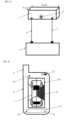
- Fig. 2 represents a diagram of a remote control 6 intended to communicate with the radar 1, according to a preferred embodiment.
- the remote control 6 has a screen for a digital display permanently displaying a diagram representing an automobile and remotely receives information concerning possible detections emitted by the hyper frequency radar 1.
- the remote control comprises a compartment for accommodating a 1.5 volt battery, of the LR003 type for example, for its power supply and in particular for the permanent digital display, the compartment has means for distinguishing the plus 10 and minus 9 polarities of said batteries.
- a diagram representing an automobile 7 is permanently displayed on the screen.
- the remote control also has an "on/off" button 12 for remotely activating or deactivating the hyper frequency radar 1. According to a particular exemplary embodiment, to activate or deactivate the detection function, it is sufficient to do so remotely from the portable remote control by pressing and holding the "on/off" button for 5 seconds.
- the remote control 6 receives by radio from the hyperfrequency radar 1 information representative of an intrusion taking place around the automobile containing the radar box 1.
- the screen of the remote control displays a permanently flashing black dot on a diagram representative of an automobile, to represent the exact geographical area where the intrusion is located around the automobile.
- the connection between the radar 1 and the remote control 6 is advantageously encrypted and secure. These two devices share the same secret key used to encrypt the information during transmission and to ensure the authenticity of this information during reception.
- the pairing step consists of simultaneously switching on the two devices and pressing and holding a button on the remote control, a pairing code is then transmitted by radio and picked up by the radar 1. The latter responds by requesting the transmission of the secret key which is thus transmitted by the remote control.
- the radio link is bidirectional, the remote control transmitting an activation order and the radar transmitting detection information.
- the frequency used by the BLE circuit is advantageously 2450 MHz or 868 MHz.
- the same remote control can be used with several radars 1 installed in different vehicles.
- the remote control has a selector to independently control each radar.
- the latter has an identifier (for example a number, or a number registration number, or the vehicle model), which is transmitted by radio in the event of detection of an object around the vehicle.
- This identifier is produced on the remote control screen during the pairing step, for example using a touch keyboard, and transmitted to the corresponding radar when the secret key is transmitted.
- this message contains the vehicle identifier for display on a screen of the remote control.
- the portable remote control 6 is equipped with a small antenna 8 one centimeter long for receiving alerts (or information) collected live and transmitted live by the hyperfrequency radar box.
- the remote control has a digital display screen (liquid crystal or LED technology). When the remote control is activated, the screen of the latter then permanently displays the representative diagram of an automobile.
- the antenna of the remote control allows it to receive remotely and by radio, live and in real time, the detection alerts transmitted by the hyperfrequency radar when an intrusion has taken place around the automobile.
- the remote control 6 has a radio range of around one hundred meters between itself and the hyperfrequency radar box 1. In this way, the user takes his remote control with him, regardless of where he is in relation to the hyperfrequency radar (at home, in an open or closed environment, etc.).
- the information collected is advantageously the subject of an alert appearing on the screen of the remote control by ringtones or vibrations.
- the hyper frequency radar detects the approach of a person or an object, it spontaneously transmits the information to said remote control.
- the remote control receives the alerts emitted by the hyper frequency radar efficiently and precisely on the protected geographical area. In this way, the remote control indicates precisely the exact position of the person or object that has approached said automobile and that is detected by the radar, for example: at the front right, at the rear right, at the front left and the rear left of the automobile.
- the remote control has an adjustment button 18 for remotely adjusting the sensitivity and detection intensity.
- the user adjusts the sensitivity depending on where it is parked. This sensitivity is only a few meters if the vehicle is in a parking lot, or it is maximum if the vehicle is in the open countryside.
- the sensitivity adjustment is carried out at the remote control level, when the radar is remotely activated, or later while the radar is activated.
- the example of realization presented at the Fig. 2 shows a screen appearance displaying a frame 30 around the vehicle, this frame is divided into 6 angular sectors representing the six detection zones of the hyper frequency radar.
- the remote control receives information from a radar detecting presence around the vehicle, it lights up the angular sector corresponding to the zone.
- a presence is detected on the right side of the vehicle and the right sector 31 appears with a visual distinction, for example by flashing or displaying a red color.
- Fig. 3 represents an automobile with the hyper frequency radar box 1 placed inside it.
- the diagram of a house as well as a person 20 inside his house, is also visible to the right of the automobile, this person being the owner of the automobile or its user. Said person is represented holding said portable remote control 6 in his hand. Note the presence of the antenna 8 of said remote control.
- the remote control has a button 12 for remotely activating or deactivating said hyper frequency radar box.
- the digital display screen of the remote control permanently displays a diagram 7 representative of an automobile as shown in the Fig. 2 .
- the hyper frequency radar box 1 is placed inside the automobile 14 and connected to the 12 volt battery 5 by two electric cables with plus and minus polarities 16, 17 used to power said hyper frequency radar box.
- the remote control When a person or object approaches the automobile according to the setting of a rotary parameter button placed on the hyperfrequency radar, the remote control then goes into alert mode by a ringing sound or by vibrations according to the desired mode and indicates the exact position of the person or object detected around the automobile by a flashing point intermittently and permanently on the digital display of said remote control.
- the hyper frequency radar When the hyper frequency radar is activated remotely from the associated remote control, the latter will deploy a more or less powerful wave field defined by the setting of the rotary adjustment button for the detection sensitivity located either on the hyper frequency radar box or on the remote control. In this way, the user can adjust the sensitivity of the radar in relation to the environment surrounding his vehicle.
- the security of the car is optimal against any malicious act (such as: theft or wheel nuts deliberately unscrewed by a malicious third party).
- the radar when the radar is activated remotely, it first emits an audible signal for a specified period, one minute for example, so as to warn any occupant of the vehicle that at the end of this time, the radar becomes active. In this way, any occupant can leave the vehicle, thus avoiding being disturbed by the microwave waves and triggering the radar when he moves to leave the vehicle.
- the radar 1 has a button to stop the specified period and not to emit the microwave waves at the end of the period during which the audible signal is emitted. In this way, if the occupant does not want to leave the vehicle for any reason, he can still stop the activation of the radar.
- the radar emits information indicating that it is deactivated by a maneuver inside the vehicle. In this way, the user of the remote control is informed of this and can either search for the occupant, get them out and activate the radar, or assume that the vehicle is occupied and does not require additional monitoring.
- Fig. 4 describes a block diagram of a circuit equipping a microwave radar.
- the radar is equipped with six Doppler effect sensors 32 whose emission axes are oriented 60° to each other horizontally around a vertical axis. Each angular sector thus covered defines a detection zone.
- the Doppler sensor emits hyper frequency waves which are reflected by obstacles. If the obstacle is moving, the return wave is slightly modified (the frequency increases or decreases by a few percent depending on whether the obstacle is moving away or approaching).
- the information from each sensor is transmitted to a central unit which analyzes the information and, in the event of detection, transmits this information to the radio module.
- the radio message is transmitted by an antenna which can advantageously be the same as that fitted to the vehicle.
Landscapes
- Engineering & Computer Science (AREA)
- Radar, Positioning & Navigation (AREA)
- Remote Sensing (AREA)
- Computer Networks & Wireless Communication (AREA)
- Physics & Mathematics (AREA)
- General Physics & Mathematics (AREA)
- Radar Systems Or Details Thereof (AREA)
- Burglar Alarm Systems (AREA)
- Geophysics And Detection Of Objects (AREA)
Claims (13)
- Alarmvorrichtung, die dazu bestimmt ist, ein Fahrzeug (14) auszurüsten, und die ein Mikrowellenradar (1) verwendet, das in der Lage ist, jede sich dem Fahrzeug nähernde Person oder jedes sich nähernde Objekt zu erfassen, wobei das Mikrowellenradar dazu bestimmt ist, im Inneren des Fahrzeugs befestigt zu werden, dadurch gekennzeichnet, dass sie außerdem eine Fernbedienung (6) umfasst, die über Funk von dem Mikrowellenradar Informationen über ein um das Fahrzeug herum stattfindendes Eindringen empfängt, wobei die Fernbedienung eine grafische Unterscheidung auf einem für das Fahrzeug repräsentativen Diagramm anzeigt, um den geografischen Bereich wie: vorne rechts, hinten rechts, vorne links und hinten links des Fahrzeugs, wo die Person oder der Gegenstand um das Fahrzeug herum erfasst wird, wobei die Alarmvorrichtung dadurch gekennzeichnet ist, dass das Radar (1) sechs Doppler-Effekt-Sensoren (32) umfasst, deren Emissionsachsen um 60° zueinander horizontal um eine vertikale Achse ausgerichtet sind, wobei jeder so erfasste Winkelsektor einen Erfassungsbereich definiert.
- Alarmvorrichtung nach Anspruch 1, dadurch gekennzeichnet, dass die Fernbedienung (6) auf einem für das Fahrzeug repräsentativen Diagramm einen ständig blinkenden schwarzen Punkt anzeigt, um den geografischen Bereich darzustellen, in dem die Person oder das Objekt um das Fahrzeug herum erfasst wird.
- Alarmvorrichtung nach Anspruch 1 oder 2, dadurch gekennzeichnet, dass die Fernbedienung (6) mit einer kleinen Antenne von einem Zentimeter Länge ausgestattet ist, um Nachrichten zu empfangen, die über eine Erfassung in der Umgebung des Fahrzeugs informieren und von dem Hyperfrequenzradar (1) live erfasst und gesendet werden.
- Alarmvorrichtung nach einem der vorhergehenden Ansprüche, dadurch gekennzeichnet, dass die Fernbedienung eine Digital- oder LED-Anzeige umfasst, deren Bildschirm, wenn sie aktiviert ist, permanent das repräsentative Diagramm eines Fahrzeugs anzeigt, wobei die Antenne der Fernbedienung es ermöglicht, aus der Ferne, live und in Echtzeit die Erkennungsmeldungen zu empfangen, die vom Mikrowellenradar ausgesendet werden, wenn ein Eindringen in die Umgebung des Fahrzeugs stattgefunden hat, die Fernbedienung verfügt über einen Bereich, in dem die gesammelten Informationen systematisch Gegenstand eines Alarms sind, der je nach gewünschtem Modus durch Glocken oder Vibrationen auf dem Bildschirm der Fernbedienung erscheint; wenn das Mikrowellenradar die Annäherung einer Person oder eines Objekts feststellt, überträgt es spontan die Informationen an die besagte Fernbedienung.
- Alarmvorrichtung nach einem der vorhergehenden Ansprüche, dadurch gekennzeichnet, dass das Radargerät (1) einen Drehknopf (2) zur Einstellung der Empfindlichkeit aufweist.
- Alarmvorrichtung nach einem der Ansprüche 1 bis 4, dadurch gekennzeichnet, dass die Fernbedienung (6) einen Drehknopf (1) zur Einstellung der Radarempfindlichkeit aufweist, wobei der Empfindlichkeitswert per Funk an das Radargerät übertragen wird.
- Alarmvorrichtung nach einem der vorhergehenden Ansprüche, dadurch gekennzeichnet, dass das Radargerät (1) im Fahrzeug in Höhe der Fenster befestigt ist, so dass die Mikrowellen leichter nach außen abgestrahlt werden können.
- Alarmvorrichtung nach Anspruch 6, dadurch gekennzeichnet, dass das Radargerät an der Decke des Fahrzeugs befestigt ist.
- Alarmanlage nach einem der vorhergehenden Ansprüche, dadurch gekennzeichnet, dass die Funkverbindung zwischen der Fernbedienung (6) und dem Radargerät durch einen Schlüssel verschlüsselt ist, der während eines Kopplungsschritts übertragen wird.
- Alarmanlage nach einem der vorhergehenden Ansprüche, dadurch gekennzeichnet, dass die Funkverbindung auf dem Frequenzband von 2450 MHz oder 868 MHz hergestellt wird.
- Alarmvorrichtung nach einem der vorhergehenden Ansprüche, dadurch gekennzeichnet, dass sie eine Vielzahl von Radargeräten (1) umfasst, die jeweils in einem Fahrzeug angeordnet sind und mit einer Kennung verbunden sind, wobei jede von einem Radargerät ausgesendete Nachricht die genannte Kennung umfasst, die von der genannten Fernbedienung (6) angezeigt wird, wenn sie eine Nachricht über die Erfassung einer Person oder eines Objekts in der Nähe des Fahrzeugs empfängt, wobei die genannte Kennung während der Kopplungsphase auf der Ebene der Fernbedienung eingegeben und an das Radargerät übertragen wird, das sie in einem Speicher aufzeichnet.
- Alarmvorrichtung nach einem der vorhergehenden Ansprüche, dadurch gekennzeichnet, dass das Radargerät (1) ein Mittel zur Abgabe eines akustischen Signals für eine bestimmte Zeitspanne nach Empfang eines Aktivierungsbefehls aufweist, wobei das Radargerät am Ende der bestimmten Zeit aktiviert wird.
- Alarmvorrichtung nach Anspruch 12, dadurch gekennzeichnet, dass das Radargerät (1) eine Taste zum Anhalten der bestimmten Zeit und zum Sperren des Betriebs des Radargeräts aufweist, wobei das Drücken der Taste die Übertragung einer Nachricht an die Fernbedienung (6) auslöst, die darüber informiert, dass das Radargerät nicht aktiviert wird.
Applications Claiming Priority (1)
| Application Number | Priority Date | Filing Date | Title |
|---|---|---|---|
| FR2009528A FR3114406B1 (fr) | 2020-09-21 | 2020-09-21 | Alarme automobile |
Publications (3)
| Publication Number | Publication Date |
|---|---|
| EP3971610A1 EP3971610A1 (de) | 2022-03-23 |
| EP3971610B1 true EP3971610B1 (de) | 2024-08-14 |
| EP3971610C0 EP3971610C0 (de) | 2024-08-14 |
Family
ID=73699014
Family Applications (1)
| Application Number | Title | Priority Date | Filing Date |
|---|---|---|---|
| EP21315164.0A Active EP3971610B1 (de) | 2020-09-21 | 2021-09-18 | Alarm für kraftfahrzeug |
Country Status (2)
| Country | Link |
|---|---|
| EP (1) | EP3971610B1 (de) |
| FR (1) | FR3114406B1 (de) |
Citations (2)
| Publication number | Priority date | Publication date | Assignee | Title |
|---|---|---|---|---|
| US4987402A (en) * | 1987-01-21 | 1991-01-22 | Electronic Security Products Of California | Alarm system for sensing and vocally warning of an unauthorized approach towards a protected object or zone |
| US5493269A (en) * | 1991-09-20 | 1996-02-20 | C.A.R.E., Inc. | Vehicular safety sensor and warning system |
Family Cites Families (2)
| Publication number | Priority date | Publication date | Assignee | Title |
|---|---|---|---|---|
| US6100792A (en) * | 1996-05-20 | 2000-08-08 | Alpine Electronics, Inc. | Car security apparatus and car security system |
| US8855621B2 (en) * | 2012-05-01 | 2014-10-07 | Innova Electronics, Inc. | Cellphone controllable car intrusion recording and monitoring reaction system |
-
2020
- 2020-09-21 FR FR2009528A patent/FR3114406B1/fr not_active Expired - Fee Related
-
2021
- 2021-09-18 EP EP21315164.0A patent/EP3971610B1/de active Active
Patent Citations (2)
| Publication number | Priority date | Publication date | Assignee | Title |
|---|---|---|---|---|
| US4987402A (en) * | 1987-01-21 | 1991-01-22 | Electronic Security Products Of California | Alarm system for sensing and vocally warning of an unauthorized approach towards a protected object or zone |
| US5493269A (en) * | 1991-09-20 | 1996-02-20 | C.A.R.E., Inc. | Vehicular safety sensor and warning system |
Also Published As
| Publication number | Publication date |
|---|---|
| EP3971610C0 (de) | 2024-08-14 |
| FR3114406B1 (fr) | 2022-08-05 |
| FR3114406A1 (fr) | 2022-03-25 |
| EP3971610A1 (de) | 2022-03-23 |
Similar Documents
| Publication | Publication Date | Title |
|---|---|---|
| EP2336990B1 (de) | Geräuschlose Diebstahlsicherungseinrichtung für der Öffentlichkeit vorgestellte Waren | |
| KR100364121B1 (ko) | 차량사고예방과 도난방지를 위한 자동경고 및 차량주변상황 영상/음향 기록장치 | |
| FR3052902B1 (fr) | Capteur d'alarme, systeme comprenant un tel capteur, et procede d'utilisation de ce systeme d'alarme | |
| EP0596805A1 (de) | Fernbetätigungssystem zum Sperren und Entsperren von Türen und Öffnungsteilen eines Kraftfahrzeugs | |
| IE86077B1 (en) | A vehicle safety apparatus | |
| JP2011162052A (ja) | 車載警報装置及び警報システム | |
| US20140327773A1 (en) | Automotive security system | |
| EP1255235B1 (de) | Fahrzeugsicherheitssystem | |
| EP3971610B1 (de) | Alarm für kraftfahrzeug | |
| CN110615054A (zh) | 一种基于nb-iot的电动车防盗报警系统 | |
| EP0377700A1 (de) | Verfahren und anordnung zur überwachung von orten, die zum abstellen von objekten verwendet werden | |
| WO2012001332A1 (fr) | Dispositif de surveillance | |
| WO2002023498A1 (fr) | Procede de mise en oeuvre et dispositif de surveillance destine a prevenir lors d'une intrusion dans la zone qu'il surveille | |
| EP0681723B1 (de) | Entstoerungsfunkvorrichtung fuer systeme zur ueberwachung des eindringens | |
| EP0588699B1 (de) | Diebstahlsicherungseinrichtung für Fahrzeuge | |
| US20050237192A1 (en) | Cable lock system | |
| WO2002011096A1 (fr) | Procede et dispositif pour la protection en continu contre les intrusions dans des locaux eventuellement habites | |
| EP3742411A2 (de) | Vorrichtung zur signalisierung der alarmposition, alarmsystem und entsprechendes verfahren | |
| GB2328053A (en) | Vehicle security system | |
| FR2645307A1 (fr) | Dispositif electronique de detection selective de personnes | |
| GB2433148A (en) | Traffic bollard alarm system for protecting against ram-raiding | |
| FR2741178A1 (fr) | Installation de protection contre le vol pour des vehicules automobiles | |
| WO2005022477A1 (en) | Alarm system for safe | |
| EP0439434A1 (de) | Alarmsystem für gepanzerte Fahrzeuge mit Wertgegenständen | |
| FR2670585A1 (fr) | Procede de controle des deplacements d'un sujet par rapport a une zone definie et dispositif correspondant. |
Legal Events
| Date | Code | Title | Description |
|---|---|---|---|
| PUAI | Public reference made under article 153(3) epc to a published international application that has entered the european phase |
Free format text: ORIGINAL CODE: 0009012 |
|
| STAA | Information on the status of an ep patent application or granted ep patent |
Free format text: STATUS: THE APPLICATION HAS BEEN PUBLISHED |
|
| AK | Designated contracting states |
Kind code of ref document: A1 Designated state(s): AL AT BE BG CH CY CZ DE DK EE ES FI FR GB GR HR HU IE IS IT LI LT LU LV MC MK MT NL NO PL PT RO RS SE SI SK SM TR |
|
| STAA | Information on the status of an ep patent application or granted ep patent |
Free format text: STATUS: REQUEST FOR EXAMINATION WAS MADE |
|
| RBV | Designated contracting states (corrected) |
Designated state(s): AL AT BE BG CH CY CZ DE DK EE ES FI FR GB GR HR HU IE IS IT LI LT LU LV MC MK MT NL NO PL PT RO RS SE SI SK SM TR |
|
| 17P | Request for examination filed |
Effective date: 20220720 |
|
| STAA | Information on the status of an ep patent application or granted ep patent |
Free format text: STATUS: EXAMINATION IS IN PROGRESS |
|
| 17Q | First examination report despatched |
Effective date: 20230519 |
|
| GRAP | Despatch of communication of intention to grant a patent |
Free format text: ORIGINAL CODE: EPIDOSNIGR1 |
|
| STAA | Information on the status of an ep patent application or granted ep patent |
Free format text: STATUS: GRANT OF PATENT IS INTENDED |
|
| GRAF | Information related to payment of grant fee modified |
Free format text: ORIGINAL CODE: EPIDOSCIGR3 |
|
| GRAS | Grant fee paid |
Free format text: ORIGINAL CODE: EPIDOSNIGR3 |
|
| RIC1 | Information provided on ipc code assigned before grant |
Ipc: G01S 7/00 20060101ALI20240531BHEP Ipc: G01S 7/10 20060101ALI20240531BHEP Ipc: G08B 13/24 20060101ALI20240531BHEP Ipc: G01S 13/56 20060101AFI20240531BHEP |
|
| GRAA | (expected) grant |
Free format text: ORIGINAL CODE: 0009210 |
|
| STAA | Information on the status of an ep patent application or granted ep patent |
Free format text: STATUS: THE PATENT HAS BEEN GRANTED |
|
| INTG | Intention to grant announced |
Effective date: 20240618 |
|
| AK | Designated contracting states |
Kind code of ref document: B1 Designated state(s): AL AT BE BG CH CY CZ DE DK EE ES FI FR GB GR HR HU IE IS IT LI LT LU LV MC MK MT NL NO PL PT RO RS SE SI SK SM TR |
|
| REG | Reference to a national code |
Ref country code: GB Ref legal event code: FG4D Free format text: NOT ENGLISH |
|
| REG | Reference to a national code |
Ref country code: CH Ref legal event code: EP |
|
| REG | Reference to a national code |
Ref country code: DE Ref legal event code: R096 Ref document number: 602021017180 Country of ref document: DE |
|
| REG | Reference to a national code |
Ref country code: CH Ref legal event code: PK Free format text: RECTIFICATIONS |
|
| REG | Reference to a national code |
Ref country code: IE Ref legal event code: FG4D Free format text: LANGUAGE OF EP DOCUMENT: FRENCH |
|
| RAP4 | Party data changed (patent owner data changed or rights of a patent transferred) |
Owner name: BOUHRA, JALAL |
|
| RIN2 | Information on inventor provided after grant (corrected) |
Inventor name: BOUHRA, JALAL |
|
| U01 | Request for unitary effect filed |
Effective date: 20240911 |
|
| U07 | Unitary effect registered |
Designated state(s): AT BE BG DE DK EE FI FR IT LT LU LV MT NL PT RO SE SI Effective date: 20240923 |
|
| U20 | Renewal fee for the european patent with unitary effect paid |
Year of fee payment: 4 Effective date: 20241002 |
|
| PG25 | Lapsed in a contracting state [announced via postgrant information from national office to epo] |
Ref country code: NO Free format text: LAPSE BECAUSE OF FAILURE TO SUBMIT A TRANSLATION OF THE DESCRIPTION OR TO PAY THE FEE WITHIN THE PRESCRIBED TIME-LIMIT Effective date: 20241114 |
|
| PG25 | Lapsed in a contracting state [announced via postgrant information from national office to epo] |
Ref country code: GR Free format text: LAPSE BECAUSE OF FAILURE TO SUBMIT A TRANSLATION OF THE DESCRIPTION OR TO PAY THE FEE WITHIN THE PRESCRIBED TIME-LIMIT Effective date: 20241115 Ref country code: PL Free format text: LAPSE BECAUSE OF FAILURE TO SUBMIT A TRANSLATION OF THE DESCRIPTION OR TO PAY THE FEE WITHIN THE PRESCRIBED TIME-LIMIT Effective date: 20240814 |
|
| PG25 | Lapsed in a contracting state [announced via postgrant information from national office to epo] |
Ref country code: IS Free format text: LAPSE BECAUSE OF FAILURE TO SUBMIT A TRANSLATION OF THE DESCRIPTION OR TO PAY THE FEE WITHIN THE PRESCRIBED TIME-LIMIT Effective date: 20241214 |
|
| PG25 | Lapsed in a contracting state [announced via postgrant information from national office to epo] |
Ref country code: HR Free format text: LAPSE BECAUSE OF FAILURE TO SUBMIT A TRANSLATION OF THE DESCRIPTION OR TO PAY THE FEE WITHIN THE PRESCRIBED TIME-LIMIT Effective date: 20240814 |
|
| PG25 | Lapsed in a contracting state [announced via postgrant information from national office to epo] |
Ref country code: RS Free format text: LAPSE BECAUSE OF FAILURE TO SUBMIT A TRANSLATION OF THE DESCRIPTION OR TO PAY THE FEE WITHIN THE PRESCRIBED TIME-LIMIT Effective date: 20241114 Ref country code: ES Free format text: LAPSE BECAUSE OF FAILURE TO SUBMIT A TRANSLATION OF THE DESCRIPTION OR TO PAY THE FEE WITHIN THE PRESCRIBED TIME-LIMIT Effective date: 20240814 |
|
| PG25 | Lapsed in a contracting state [announced via postgrant information from national office to epo] |
Ref country code: RS Free format text: LAPSE BECAUSE OF FAILURE TO SUBMIT A TRANSLATION OF THE DESCRIPTION OR TO PAY THE FEE WITHIN THE PRESCRIBED TIME-LIMIT Effective date: 20241114 Ref country code: PL Free format text: LAPSE BECAUSE OF FAILURE TO SUBMIT A TRANSLATION OF THE DESCRIPTION OR TO PAY THE FEE WITHIN THE PRESCRIBED TIME-LIMIT Effective date: 20240814 Ref country code: NO Free format text: LAPSE BECAUSE OF FAILURE TO SUBMIT A TRANSLATION OF THE DESCRIPTION OR TO PAY THE FEE WITHIN THE PRESCRIBED TIME-LIMIT Effective date: 20241114 Ref country code: IS Free format text: LAPSE BECAUSE OF FAILURE TO SUBMIT A TRANSLATION OF THE DESCRIPTION OR TO PAY THE FEE WITHIN THE PRESCRIBED TIME-LIMIT Effective date: 20241214 Ref country code: HR Free format text: LAPSE BECAUSE OF FAILURE TO SUBMIT A TRANSLATION OF THE DESCRIPTION OR TO PAY THE FEE WITHIN THE PRESCRIBED TIME-LIMIT Effective date: 20240814 Ref country code: GR Free format text: LAPSE BECAUSE OF FAILURE TO SUBMIT A TRANSLATION OF THE DESCRIPTION OR TO PAY THE FEE WITHIN THE PRESCRIBED TIME-LIMIT Effective date: 20241115 Ref country code: ES Free format text: LAPSE BECAUSE OF FAILURE TO SUBMIT A TRANSLATION OF THE DESCRIPTION OR TO PAY THE FEE WITHIN THE PRESCRIBED TIME-LIMIT Effective date: 20240814 |
|
| PG25 | Lapsed in a contracting state [announced via postgrant information from national office to epo] |
Ref country code: SM Free format text: LAPSE BECAUSE OF FAILURE TO SUBMIT A TRANSLATION OF THE DESCRIPTION OR TO PAY THE FEE WITHIN THE PRESCRIBED TIME-LIMIT Effective date: 20240814 |
|
| PG25 | Lapsed in a contracting state [announced via postgrant information from national office to epo] |
Ref country code: CZ Free format text: LAPSE BECAUSE OF FAILURE TO SUBMIT A TRANSLATION OF THE DESCRIPTION OR TO PAY THE FEE WITHIN THE PRESCRIBED TIME-LIMIT Effective date: 20240814 |
|
| PG25 | Lapsed in a contracting state [announced via postgrant information from national office to epo] |
Ref country code: SK Free format text: LAPSE BECAUSE OF FAILURE TO SUBMIT A TRANSLATION OF THE DESCRIPTION OR TO PAY THE FEE WITHIN THE PRESCRIBED TIME-LIMIT Effective date: 20240814 |
|
| REG | Reference to a national code |
Ref country code: CH Ref legal event code: PL |
|
| PLBE | No opposition filed within time limit |
Free format text: ORIGINAL CODE: 0009261 |
|
| STAA | Information on the status of an ep patent application or granted ep patent |
Free format text: STATUS: NO OPPOSITION FILED WITHIN TIME LIMIT |
|
| PG25 | Lapsed in a contracting state [announced via postgrant information from national office to epo] |
Ref country code: MC Free format text: LAPSE BECAUSE OF FAILURE TO SUBMIT A TRANSLATION OF THE DESCRIPTION OR TO PAY THE FEE WITHIN THE PRESCRIBED TIME-LIMIT Effective date: 20240814 |
|
| 26N | No opposition filed |
Effective date: 20250515 |
|
| PG25 | Lapsed in a contracting state [announced via postgrant information from national office to epo] |
Ref country code: CH Free format text: LAPSE BECAUSE OF NON-PAYMENT OF DUE FEES Effective date: 20240930 |
|
| PG25 | Lapsed in a contracting state [announced via postgrant information from national office to epo] |
Ref country code: IE Free format text: LAPSE BECAUSE OF NON-PAYMENT OF DUE FEES Effective date: 20240918 |
|
| U79 | Statement concerning licences of right filed [unitary effect] |
Effective date: 20250714 |
|
| U20 | Renewal fee for the european patent with unitary effect paid |
Year of fee payment: 5 Effective date: 20250805 |
|
| PG25 | Lapsed in a contracting state [announced via postgrant information from national office to epo] |
Ref country code: CY Free format text: LAPSE BECAUSE OF FAILURE TO SUBMIT A TRANSLATION OF THE DESCRIPTION OR TO PAY THE FEE WITHIN THE PRESCRIBED TIME-LIMIT; INVALID AB INITIO Effective date: 20210918 |
|
| PG25 | Lapsed in a contracting state [announced via postgrant information from national office to epo] |
Ref country code: HU Free format text: LAPSE BECAUSE OF FAILURE TO SUBMIT A TRANSLATION OF THE DESCRIPTION OR TO PAY THE FEE WITHIN THE PRESCRIBED TIME-LIMIT; INVALID AB INITIO Effective date: 20210918 |