EP3971580A1 - Automated analyzer - Google Patents
Automated analyzer Download PDFInfo
- Publication number
- EP3971580A1 EP3971580A1 EP20806850.2A EP20806850A EP3971580A1 EP 3971580 A1 EP3971580 A1 EP 3971580A1 EP 20806850 A EP20806850 A EP 20806850A EP 3971580 A1 EP3971580 A1 EP 3971580A1
- Authority
- EP
- European Patent Office
- Prior art keywords
- unit
- preprocessing
- reaction vessel
- movement unit
- rotational movement
- Prior art date
- Legal status (The legal status is an assumption and is not a legal conclusion. Google has not performed a legal analysis and makes no representation as to the accuracy of the status listed.)
- Granted
Links
Images


Classifications
-
- G—PHYSICS
- G01—MEASURING; TESTING
- G01N—INVESTIGATING OR ANALYSING MATERIALS BY DETERMINING THEIR CHEMICAL OR PHYSICAL PROPERTIES
- G01N35/00—Automatic analysis not limited to methods or materials provided for in any single one of groups G01N1/00 - G01N33/00; Handling materials therefor
- G01N35/02—Automatic analysis not limited to methods or materials provided for in any single one of groups G01N1/00 - G01N33/00; Handling materials therefor using a plurality of sample containers moved by a conveyor system past one or more treatment or analysis stations
- G01N35/04—Details of the conveyor system
-
- G—PHYSICS
- G01—MEASURING; TESTING
- G01N—INVESTIGATING OR ANALYSING MATERIALS BY DETERMINING THEIR CHEMICAL OR PHYSICAL PROPERTIES
- G01N35/00—Automatic analysis not limited to methods or materials provided for in any single one of groups G01N1/00 - G01N33/00; Handling materials therefor
- G01N35/02—Automatic analysis not limited to methods or materials provided for in any single one of groups G01N1/00 - G01N33/00; Handling materials therefor using a plurality of sample containers moved by a conveyor system past one or more treatment or analysis stations
- G01N35/025—Automatic analysis not limited to methods or materials provided for in any single one of groups G01N1/00 - G01N33/00; Handling materials therefor using a plurality of sample containers moved by a conveyor system past one or more treatment or analysis stations having a carousel or turntable for reaction cells or cuvettes
-
- G—PHYSICS
- G01—MEASURING; TESTING
- G01N—INVESTIGATING OR ANALYSING MATERIALS BY DETERMINING THEIR CHEMICAL OR PHYSICAL PROPERTIES
- G01N35/00—Automatic analysis not limited to methods or materials provided for in any single one of groups G01N1/00 - G01N33/00; Handling materials therefor
- G01N35/10—Devices for transferring samples or any liquids to, in, or from, the analysis apparatus, e.g. suction devices, injection devices
- G01N35/1002—Reagent dispensers
-
- G—PHYSICS
- G01—MEASURING; TESTING
- G01N—INVESTIGATING OR ANALYSING MATERIALS BY DETERMINING THEIR CHEMICAL OR PHYSICAL PROPERTIES
- G01N35/00—Automatic analysis not limited to methods or materials provided for in any single one of groups G01N1/00 - G01N33/00; Handling materials therefor
- G01N35/10—Devices for transferring samples or any liquids to, in, or from, the analysis apparatus, e.g. suction devices, injection devices
- G01N35/1081—Devices for transferring samples or any liquids to, in, or from, the analysis apparatus, e.g. suction devices, injection devices characterised by the means for relatively moving the transfer device and the containers in an horizontal plane
- G01N35/109—Devices for transferring samples or any liquids to, in, or from, the analysis apparatus, e.g. suction devices, injection devices characterised by the means for relatively moving the transfer device and the containers in an horizontal plane with two horizontal degrees of freedom
-
- G—PHYSICS
- G01—MEASURING; TESTING
- G01N—INVESTIGATING OR ANALYSING MATERIALS BY DETERMINING THEIR CHEMICAL OR PHYSICAL PROPERTIES
- G01N35/00—Automatic analysis not limited to methods or materials provided for in any single one of groups G01N1/00 - G01N33/00; Handling materials therefor
- G01N35/02—Automatic analysis not limited to methods or materials provided for in any single one of groups G01N1/00 - G01N33/00; Handling materials therefor using a plurality of sample containers moved by a conveyor system past one or more treatment or analysis stations
- G01N35/04—Details of the conveyor system
- G01N2035/0401—Sample carriers, cuvettes or reaction vessels
- G01N2035/0406—Individual bottles or tubes
-
- G—PHYSICS
- G01—MEASURING; TESTING
- G01N—INVESTIGATING OR ANALYSING MATERIALS BY DETERMINING THEIR CHEMICAL OR PHYSICAL PROPERTIES
- G01N35/00—Automatic analysis not limited to methods or materials provided for in any single one of groups G01N1/00 - G01N33/00; Handling materials therefor
- G01N35/02—Automatic analysis not limited to methods or materials provided for in any single one of groups G01N1/00 - G01N33/00; Handling materials therefor using a plurality of sample containers moved by a conveyor system past one or more treatment or analysis stations
- G01N35/04—Details of the conveyor system
- G01N2035/0401—Sample carriers, cuvettes or reaction vessels
- G01N2035/0418—Plate elements with several rows of samples
- G01N2035/0422—Plate elements with several rows of samples carried on a linear conveyor
-
- G—PHYSICS
- G01—MEASURING; TESTING
- G01N—INVESTIGATING OR ANALYSING MATERIALS BY DETERMINING THEIR CHEMICAL OR PHYSICAL PROPERTIES
- G01N35/00—Automatic analysis not limited to methods or materials provided for in any single one of groups G01N1/00 - G01N33/00; Handling materials therefor
- G01N35/02—Automatic analysis not limited to methods or materials provided for in any single one of groups G01N1/00 - G01N33/00; Handling materials therefor using a plurality of sample containers moved by a conveyor system past one or more treatment or analysis stations
- G01N35/04—Details of the conveyor system
- G01N2035/0439—Rotary sample carriers, i.e. carousels
-
- G—PHYSICS
- G01—MEASURING; TESTING
- G01N—INVESTIGATING OR ANALYSING MATERIALS BY DETERMINING THEIR CHEMICAL OR PHYSICAL PROPERTIES
- G01N35/00—Automatic analysis not limited to methods or materials provided for in any single one of groups G01N1/00 - G01N33/00; Handling materials therefor
- G01N35/02—Automatic analysis not limited to methods or materials provided for in any single one of groups G01N1/00 - G01N33/00; Handling materials therefor using a plurality of sample containers moved by a conveyor system past one or more treatment or analysis stations
- G01N35/04—Details of the conveyor system
- G01N2035/0474—Details of actuating means for conveyors or pipettes
- G01N2035/0491—Position sensing, encoding; closed-loop control
Definitions
- the present invention relates to an automatic analyzer.
- the automatic analyzer is a device for automatically quantitatively or qualitatively analyzing a specific component contained in a sample such as blood or urine. Automatic analyzers are required to perform a wide variety of inspections in a shorter time and in a smaller space.
- Patent Literature 1 discloses an automatic analyzer including a reagent dispensing probe that moves along a rail connecting a plurality of reagent disks and accesses to the plurality of reagent disks to increase processing capacity even with a small size and a large number of reagents loaded.
- the automatic analyzer includes a plurality of movement units that access to the same location from different directions, and also includes a space that requires a uniform temperature distribution. Thus, if the space saving in the space is insufficient, it is difficult to maintain a uniform temperature distribution.
- an object of the invention is to provide an automatic analyzer in which a linear movement unit and a rotational movement unit that access to the same location can be arranged in the same plane.
- the invention provides an automatic analyzer including a linear movement unit configured to access to an access point by a linear movement, a rotational movement unit configured to access to the access point by a rotational movement, and a control unit configured to control an operation of the linear movement unit and the rotational movement unit so that the linear movement unit and the rotational movement unit do not interfere with each other.
- an automatic analyzer in which a linear movement unit and a rotational movement unit that access to the same location can be arranged in the same plane.
- the automatic analyzer is a device that analyzes a sample using a reaction liquid obtained by causing a reagent to react with a sample such as blood or urine with a reagent.
- the automatic analyzer includes a sample transport unit 102, a reagent disk 104, a sample dispensing unit 105, a reagent dispensing unit 106, a reaction disk 107, a reaction vessel transport unit 109, a preprocessing probe 114, a measurement unit 108, and a control unit 113.
- a vertical direction is defined as a Z direction
- a horizontal plane is defined as an XY plane.
- the sample transport unit 102 transports a sample container 101 containing a sample such as blood or urine to a sample aspiration position 110.
- the reagent disk 104 stores a reagent container 103 containing a reagent used for analysis in a predetermined temperature range.
- the sample dispensing unit 105 dispenses a sample from the sample container 101 transported to the sample aspiration position 110 to a reaction vessel arranged on the reaction disk 107.
- the reaction vessel into which the sample is dispensed and a dispensing chip used when dispensing the sample are stored in a consumable storage unit 111, and are transported to a predetermined position by a consumable transport unit 112.
- the reagent dispensing unit 106 dispenses a reagent from the reagent container 103 stored in the reagent disk 104 to the reaction vessel arranged on the reaction disk 107 and dispensed with the sample.
- the reaction disk 107 promotes a reaction between the sample and the reagent and produces a reaction liquid by maintaining the reaction vessel in which the sample and the reagent are dispensed within a predetermined temperature range.
- the reaction vessel transport unit 109 transports the reaction vessel containing the reaction liquid from the reaction disk 107 to a reaction liquid dispensing position 117 via a preprocessing position 115 and a stirring position 116.
- the preprocessing probe 114 As a preprocessing for the reaction liquid contained in the reaction vessel, the preprocessing probe 114 aspirates an unnecessary liquid and discharges a buffer liquid.
- the reaction liquid is stirred at the stirring position 116.
- the reaction liquid dispensing position 117 the reaction liquid is supplied from the reaction vessel to the measurement unit 108 by a probe for the measurement unit, which is not shown.
- the measurement unit 108 measures physical properties of the supplied reaction liquid, for example, a light emission mount, a scattered light amount, a transmitted light amount, a current value, a voltage value, and the like.
- the physical properties to be measured are not limited to these.
- the measurement unit 108 may receive the reaction vessel from the reaction vessel transport unit 109 and measure the physical properties of the reaction liquid while being contained in the reaction vessel.
- the reaction vessel containing the reaction liquid of which the physical properties have been measured by the measurement unit 108 is transported to a disposal outlet 118 by the reaction vessel transport unit 109 and discarded. In addition, the discarded reaction vessel may be washed and reused.
- the control unit 113 is a device that controls each unit included in the automatic analyzer, and is implemented by, for example, a computer.
- the reaction disk 107, the preprocessing probe 114, the preprocessing position 115, the stirring position 116, the reaction liquid dispensing position 117, the measurement unit 108, and the reaction vessel transport unit 109 are covered with a thermal insulation cover 119 made of a thermal insulation material.
- a space inside the thermal insulation cover 119 is adjusted to a predetermined temperature . If the space covered by the thermal insulation cover 119 becomes wide, it becomes difficult to maintain a uniform temperature distribution, and the time required for reaching a set temperature, that is, the time required for the measurement unit 108 to start the measurement becomes long. Therefore, it is desirable to save space in the thermal insulation cover 119.
- reaction vessel transport unit 109 which is a linear movement unit that accesses to the preprocessing position 115, which is a common access point, by a linear movement
- preprocessing probe 114 which is a rotational movement unit that accesses to the preprocessing position 115 by a rotational movement
- the reaction vessel transport unit 109 accesses to the preprocessing position 115, which is the access point, in a linearly moving process within a linear movement range 201, and waits at an origin when not transporting the reaction vessel.
- a linear movement unit origin sensor 200 is provided at the origin of the reaction vessel transport unit 109, and the linear movement unit origin sensor 200 detects whether the reaction vessel transport unit 109 is waiting at the origin.
- reaction vessel transport unit 109A at one end of the linear movement range 201, a reaction vessel transport unit 109C at the origin, and a reaction vessel transport unit 109B between these two.
- the reaction vessel transport unit 109 has a shape that is inclined forward with respect to a direction of returning to the origin.
- the preprocessing probe 114 accesses to the preprocessing position 115 by moving rotationally around a rotation center 212 as a rotation axis within a rotational movement range 211, and waits at an origin when not accessing to the preprocessing position 115.
- a rotational movement unit origin sensor 210 is provided at the origin of the preprocessing probe 114, and the rotational movement unit origin sensor 210 detects whether the preprocessing probe 114 is waiting at the origin.
- preprocessing probe 114A at the preprocessing position 115, which is one end of the rotational movement range 211, a preprocessing probe 114C at the origin, and a preprocessing probe 114B between these two.
- the reaction vessel transport unit 109 and the preprocessing probe 114 arranged as shown in FIG. 2 are controlled by the control unit 113 so that the reaction vessel transport unit 109 and the preprocessing probe 114 do not interfere with each other based on the movement distances from the origins during a normal operation.
- the reaction vessel transport unit 109 and the preprocessing probe 114 may interfere with each other when returning to the origins when the reaction vessel transport unit 109 or the preprocessing probe 114 stops at a position where the control unit 113 cannot recognize due to an operator touching the reaction vessel transport unit 109 or the preprocessing probe 114 or the like.
- control is performed so that the reaction vessel transport section 109 and the preprocessing probe 114 can return to the origins without interfering with each other regardless of the position at which the reaction vessel transport section 109, which is the linear movement unit, and the preprocessing probe 114, which is the rotational movement unit, stop.
- the control unit 113 controls the operation of each unit of the automatic analyzer, and the control unit 113 controls the reaction vessel transport unit 109, which is the linear movement unit, and the preprocessing probe 114, which is the rotational movement unit, so that the reaction vessel transport unit 109 and the preprocessing probe 114 do not interfere with each other.
- the control unit 113 first instructs a reset operation of each mechanism. That is, by performing an origin return operation before starting all of the operations, it is possible to return to the origin position and start a normal operation even after an abnormal operation.
- the control unit 113 acquires a movement speed Vx at which the reaction vessel transport unit 109, which is the linear movement unit, returns to the origin.
- the movement speed Vx may be stored in advance in a storage unit or the like included in the control unit 113.
- the control unit 113 sets a movement speed Vr at which the preprocessing probe 114, which is the rotational movement unit, returns to the origin, based on the movement speed Vx.
- the movement speed Vr is set to be larger than the movement speed Vx.
- the movement speed Vr is a speed in a circumferential direction of a tip end portion of the rotational movement unit.
- the control unit 113 linearly moves the linear movement unit at the movement speed Vx, and rotationally moves the rotational movement unit at the moving speed Vr to return the linear movement unit and the rotational movement unit to respective origins.
- the linear movement unit has a shape with an opening space in a movement direction of the rotational movement unit. Since the linear movement unit has the opening space in the movement direction of the rotational movement unit, and the rotational movement unit moves at a speed larger than that of the linear movement unit, the linear movement unit and the rotational movement unit can return to the origins without interfering with each other.
- detailed conditions for avoiding the interference between the linear movement unit and the rotational movement unit will be described.
- reaction vessel transport section 109 which is the linear movement unit
- the preprocessing probe 114 which is the rotational movement unit
- the vector of the Y-direction component Vr ⁇ sin(9R) of the movement speed of the preprocessing probe 114 is the direction away from the reaction vessel transport unit 109, and the reaction vessel transport unit 109 has the opening space in the movement direction of the preprocessing probe 114. Therefore, the interference between the preprocessing probe 114 and the reaction vessel transport unit 109 can be avoided by moving the preprocessing probe 114 in both the X and Y directions at a speed larger than that of the reaction vessel transport unit 109.
- Vr ⁇ cos( ⁇ R) > Vx is satisfied in the X direction
- Vr ⁇ sin( ⁇ R) > Vx/tan( ⁇ L) is satisfied in the Y direction.
- the reaction vessel transport unit 109 has the shape that is inclined backward, and thus the reaction vessel transport unit 109 has the opening space in the direction of the vector of the Y-direction component Vr ⁇ sin( ⁇ R - 90) of the movement speed of the preprocessing probe 114. Therefore, the interference between the preprocessing probe 114 and the reaction vessel transport unit 109 can be avoided by moving the preprocessing probe 114 in both the X and Y directions at a speed larger than that of the reaction vessel transport unit 109.
- Vr ⁇ cos ( ⁇ R - 90) > Vx is satisfied in the X direction
- Vr ⁇ sin( ⁇ R - 90) > Vx/tan (180 - ⁇ L) is satisfied in the Y direction.
- the reaction vessel transport unit 109 has a shape that is inclined backward, and the preprocessing probe 114 moves in the direction away from the reaction vessel transport unit 109 in the Y direction, and thus the reaction vessel transport unit 109 has the opening space in the movement direction of the preprocessing probe 114. Therefore, the interference between the preprocessing probe 114 and the reaction vessel transport unit 109 can be avoided by moving the preprocessing probe 114 in the X direction at a speed larger than that of the reaction vessel transport unit 109, that is, Vr ⁇ cos( ⁇ R) > Vx.
- FIG. 6 A case where the preprocessing probe 114, which is the rotational movement unit, is provided backward than the reaction vessel transport unit 109, which is the linear movement unit, will be described with reference to FIG. 6 .
- (a) of FIG. 6 is a plan view showing a case where the reaction vessel transport unit 109 has a shape that is tilted forward
- (b) of FIG. 6 is a plan view showing a case where the reaction vessel transport unit 109 has a shape that is tilted backward.
- the preprocessing probe 114 moves in the direction away from the reaction vessel transport unit 109 in the Y direction, and thus the reaction vessel transport unit 109 has the opening space in the movement direction of the preprocessing probe 114.
- the preprocessing probe 114 moves in the direction approaching the reaction vessel transport unit 109 in the X direction. Therefore, a notch as shown in FIG. 2 may be provided on the wall opposite to the origin of the reaction vessel transport unit 109 so that the reaction vessel transport unit 109 has the opening space in the movement direction of the preprocessing probe 114.
- the interference between the preprocessing probe 114 and the reaction vessel transport unit 109 can be avoided by having the opening space in the movement direction of the preprocessing probe 114 and moving the preprocessing probe 114 at a speed larger than that of the reaction vessel transport unit 109.
- the reaction vessel transport unit 109 it becomes easy to form the opening space of the reaction vessel transport unit 109 by limiting the rotational movement range 211 of the preprocessing probe 114 such that the rotation angle ⁇ R of the preprocessing probe 114 when accessing to the preprocessing position 115 is less than 90°.
- the reaction container transport unit 109 may be returned to the origin after the preprocessing probe 114 is returned to the origin.
- Embodiments of the invention are described above.
- the invention is not limited to the above embodiments, and the constituent elements may be modified without departing from the scope of the invention.
- a plurality of constituent elements disclosed in the above embodiments may be appropriately combined.
- some constituent elements may be omitted from all the constituent elements shown in the above embodiments.
Landscapes
- Chemical & Material Sciences (AREA)
- Physics & Mathematics (AREA)
- Health & Medical Sciences (AREA)
- Life Sciences & Earth Sciences (AREA)
- Analytical Chemistry (AREA)
- Biochemistry (AREA)
- General Health & Medical Sciences (AREA)
- General Physics & Mathematics (AREA)
- Immunology (AREA)
- Pathology (AREA)
- Chemical Kinetics & Catalysis (AREA)
- Automatic Analysis And Handling Materials Therefor (AREA)
Abstract
Description
- The present invention relates to an automatic analyzer.
- The automatic analyzer is a device for automatically quantitatively or qualitatively analyzing a specific component contained in a sample such as blood or urine. Automatic analyzers are required to perform a wide variety of inspections in a shorter time and in a smaller space.
-
Patent Literature 1 discloses an automatic analyzer including a reagent dispensing probe that moves along a rail connecting a plurality of reagent disks and accesses to the plurality of reagent disks to increase processing capacity even with a small size and a large number of reagents loaded. - PTL 1:
JP-A-2004-45112 - However, in
PTL 1, since the reagent disk moving rotationally and the reagent dispensing probe moving linearly along the rail and accessing to the reagent disk are arranged at different heights, interference therebetween can be avoided, whereas space saving in a height direction is insufficient. The automatic analyzer includes a plurality of movement units that access to the same location from different directions, and also includes a space that requires a uniform temperature distribution. Thus, if the space saving in the space is insufficient, it is difficult to maintain a uniform temperature distribution. - Therefore, an object of the invention is to provide an automatic analyzer in which a linear movement unit and a rotational movement unit that access to the same location can be arranged in the same plane.
- In order to achieve the above object, the invention provides an automatic analyzer including a linear movement unit configured to access to an access point by a linear movement, a rotational movement unit configured to access to the access point by a rotational movement, and a control unit configured to control an operation of the linear movement unit and the rotational movement unit so that the linear movement unit and the rotational movement unit do not interfere with each other.
- According to the invention, it is possible to provide an automatic analyzer in which a linear movement unit and a rotational movement unit that access to the same location can be arranged in the same plane.
-
- [
FIG. 1] FIG. 1 is a plan view showing a configuration example of an automatic analyzer. - [
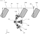
FIG. 2] FIG. 2 is a plan view showing an arrangement of a reaction vessel transport unit (a linear movement unit), a preprocessing probe (a rotational movement unit), and a preprocessing position (an access point). - [
FIG. 3] FIG. 3 is a diagram showing a processing flow of controlling an operation of the linear movement unit and the rotational movement unit. - [
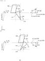
FIG. 4] FIG. 4 is a plan view showing a case where the rotational movement unit is provided frontward than the linear movement unit that is inclined forward with respect to a movement direction. - [
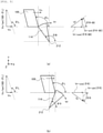
FIG. 5] FIG. 5 is a plan view showing a case where the rotational movement unit is provided frontward than the linear movement unit that is inclined backward with respect to the movement direction. - [
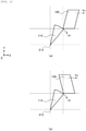
FIG. 6] FIG. 6 is a plan view showing a case where the rotational movement unit is provided backward than the linear movement unit. - Hereinafter, preferred embodiments of an automatic analyzer according to the invention will be described with reference to the accompanying drawings. The automatic analyzer is a device that analyzes a sample using a reaction liquid obtained by causing a reagent to react with a sample such as blood or urine with a reagent.
- An example of an overall configuration of an automatic analyzer of the present embodiment will be described with reference to
FIG. 1 . The automatic analyzer includes asample transport unit 102, areagent disk 104, asample dispensing unit 105, areagent dispensing unit 106, areaction disk 107, a reactionvessel transport unit 109, apreprocessing probe 114, ameasurement unit 108, and acontrol unit 113. Hereinafter, each unit will be described. In addition, a vertical direction is defined as a Z direction, and a horizontal plane is defined as an XY plane. - The
sample transport unit 102 transports asample container 101 containing a sample such as blood or urine to asample aspiration position 110. Thereagent disk 104 stores areagent container 103 containing a reagent used for analysis in a predetermined temperature range. - The
sample dispensing unit 105 dispenses a sample from thesample container 101 transported to thesample aspiration position 110 to a reaction vessel arranged on thereaction disk 107. In addition, the reaction vessel into which the sample is dispensed and a dispensing chip used when dispensing the sample are stored in aconsumable storage unit 111, and are transported to a predetermined position by aconsumable transport unit 112. Thereagent dispensing unit 106 dispenses a reagent from thereagent container 103 stored in thereagent disk 104 to the reaction vessel arranged on thereaction disk 107 and dispensed with the sample. Thereaction disk 107 promotes a reaction between the sample and the reagent and produces a reaction liquid by maintaining the reaction vessel in which the sample and the reagent are dispensed within a predetermined temperature range. - The reaction
vessel transport unit 109 transports the reaction vessel containing the reaction liquid from thereaction disk 107 to a reactionliquid dispensing position 117 via a preprocessingposition 115 and a stirringposition 116. At thepreprocessing position 115, as a preprocessing for the reaction liquid contained in the reaction vessel, thepreprocessing probe 114 aspirates an unnecessary liquid and discharges a buffer liquid. Next, the reaction liquid is stirred at the stirringposition 116. Then, at the reactionliquid dispensing position 117, the reaction liquid is supplied from the reaction vessel to themeasurement unit 108 by a probe for the measurement unit, which is not shown. - The
measurement unit 108 measures physical properties of the supplied reaction liquid, for example, a light emission mount, a scattered light amount, a transmitted light amount, a current value, a voltage value, and the like. In addition, the physical properties to be measured are not limited to these. In addition, themeasurement unit 108 may receive the reaction vessel from the reactionvessel transport unit 109 and measure the physical properties of the reaction liquid while being contained in the reaction vessel. The reaction vessel containing the reaction liquid of which the physical properties have been measured by themeasurement unit 108 is transported to adisposal outlet 118 by the reactionvessel transport unit 109 and discarded. In addition, the discarded reaction vessel may be washed and reused. - The
control unit 113 is a device that controls each unit included in the automatic analyzer, and is implemented by, for example, a computer. - The
reaction disk 107, thepreprocessing probe 114, thepreprocessing position 115, thestirring position 116, the reactionliquid dispensing position 117, themeasurement unit 108, and the reactionvessel transport unit 109 are covered with athermal insulation cover 119 made of a thermal insulation material. In order to maintain the accuracy of the measurement result by themeasurement unit 108, a space inside thethermal insulation cover 119 is adjusted to a predetermined temperature . If the space covered by thethermal insulation cover 119 becomes wide, it becomes difficult to maintain a uniform temperature distribution, and the time required for reaching a set temperature, that is, the time required for themeasurement unit 108 to start the measurement becomes long. Therefore, it is desirable to save space in thethermal insulation cover 119. - In addition, since both the reaction
vessel transport unit 109 and thepreprocessing probe 114 provided in thethermal insulation cover 119 access to the preprocessingposition 115, it is necessary to avoid interference therebetween when arranging these two on the same plane for space saving. That is, the reactionvessel transport unit 109, which is a linear movement unit that accesses to thepreprocessing position 115, which is a common access point, by a linear movement, and thepreprocessing probe 114, which is a rotational movement unit that accesses to the preprocessingposition 115 by a rotational movement, are arranged in the same plane, and are not interfered with each other. - An example of an arrangement of the reaction
vessel transport unit 109, thepreprocessing probe 114, and thepreprocessing position 115 according to the present embodiment will be described with reference toFIG. 2 . The reactionvessel transport unit 109 accesses to thepreprocessing position 115, which is the access point, in a linearly moving process within alinear movement range 201, and waits at an origin when not transporting the reaction vessel. A linear movementunit origin sensor 200 is provided at the origin of the reactionvessel transport unit 109, and the linear movementunit origin sensor 200 detects whether the reactionvessel transport unit 109 is waiting at the origin. By providing at least the linear movementunit origin sensor 200 as a sensor for detecting the position of the reactionvessel transport unit 109, cost reduction and simple system design can be achieved.FIG. 2 exemplifies a reactionvessel transport unit 109A at one end of thelinear movement range 201, a reactionvessel transport unit 109C at the origin, and a reactionvessel transport unit 109B between these two. In addition, the reactionvessel transport unit 109 has a shape that is inclined forward with respect to a direction of returning to the origin. - The
preprocessing probe 114 accesses to thepreprocessing position 115 by moving rotationally around arotation center 212 as a rotation axis within arotational movement range 211, and waits at an origin when not accessing to thepreprocessing position 115. A rotational movementunit origin sensor 210 is provided at the origin of thepreprocessing probe 114, and the rotational movementunit origin sensor 210 detects whether thepreprocessing probe 114 is waiting at the origin. By providing at least the rotational movementunit origin sensor 210 as a sensor for detecting the position of the preprocessingprobe 114, cost reduction and simple system design can be achieved.FIG. 2 exemplifies apreprocessing probe 114A at thepreprocessing position 115, which is one end of therotational movement range 211, apreprocessing probe 114C at the origin, and apreprocessing probe 114B between these two. - The reaction
vessel transport unit 109 and thepreprocessing probe 114 arranged as shown inFIG. 2 are controlled by thecontrol unit 113 so that the reactionvessel transport unit 109 and thepreprocessing probe 114 do not interfere with each other based on the movement distances from the origins during a normal operation. However, the reactionvessel transport unit 109 and thepreprocessing probe 114 may interfere with each other when returning to the origins when the reactionvessel transport unit 109 or thepreprocessing probe 114 stops at a position where thecontrol unit 113 cannot recognize due to an operator touching the reactionvessel transport unit 109 or thepreprocessing probe 114 or the like. Therefore, in the present embodiment, control is performed so that the reactionvessel transport section 109 and thepreprocessing probe 114 can return to the origins without interfering with each other regardless of the position at which the reactionvessel transport section 109, which is the linear movement unit, and thepreprocessing probe 114, which is the rotational movement unit, stop. - An example of a processing flow of controlling the operation of the linear movement unit and the rotational movement unit according to the present embodiment will be described with reference to
FIG. 3 . - The
control unit 113 controls the operation of each unit of the automatic analyzer, and thecontrol unit 113 controls the reactionvessel transport unit 109, which is the linear movement unit, and thepreprocessing probe 114, which is the rotational movement unit, so that the reactionvessel transport unit 109 and thepreprocessing probe 114 do not interfere with each other. When receiving an instruction for a certain operation, thecontrol unit 113 first instructs a reset operation of each mechanism. That is, by performing an origin return operation before starting all of the operations, it is possible to return to the origin position and start a normal operation even after an abnormal operation. - The
control unit 113 acquires a movement speed Vx at which the reactionvessel transport unit 109, which is the linear movement unit, returns to the origin. The movement speed Vx may be stored in advance in a storage unit or the like included in thecontrol unit 113. - The
control unit 113 sets a movement speed Vr at which thepreprocessing probe 114, which is the rotational movement unit, returns to the origin, based on the movement speed Vx. For example, the movement speed Vr is set to be larger than the movement speed Vx. In addition, the movement speed Vr is a speed in a circumferential direction of a tip end portion of the rotational movement unit. - The
control unit 113 linearly moves the linear movement unit at the movement speed Vx, and rotationally moves the rotational movement unit at the moving speed Vr to return the linear movement unit and the rotational movement unit to respective origins. In addition, the linear movement unit has a shape with an opening space in a movement direction of the rotational movement unit. Since the linear movement unit has the opening space in the movement direction of the rotational movement unit, and the rotational movement unit moves at a speed larger than that of the linear movement unit, the linear movement unit and the rotational movement unit can return to the origins without interfering with each other. Hereinafter, detailed conditions for avoiding the interference between the linear movement unit and the rotational movement unit will be described. - A condition under which the linear movement unit and the rotational movement unit return to the origins without interfering with each other when the reaction
vessel transport unit 109, which is the linear movement unit, has a shape that is inclined forward with respect to the direction of returning to the origin, and thepreprocessing probe 114, which is the rotational movement unit, is provided frontward than the linear movement unit, will be described with reference toFIG. 4 . In addition, when the reactionvessel transport unit 109 has the shape that is inclined forward with respect to the direction of returning to the origin, an angle θL formed by a wall on the origin side of the reactionvessel transport unit 109 and the movement direction is less than 90°. In addition, when the rotation angle of thepreprocessing probe 114 around therotation center 212 is an angle θR formed by a wall opposite to the origin of thepreprocessing probe 114 and the movement direction of the reactionvessel transport unit 109, (a) ofFIG. 4 is a plan view when θR ≥ 90°, and (b) ofFIG. 4 is a plan view when θR < 90°. - In the case of (a) of
FIG. 4 , by making an X-direction component Vr·cos(θR - 90) of the movement speed of thepreprocessing probe 114 larger than the movement speed Vx of the reactionvessel transport unit 109, the interference in the X direction can be avoided, whereas thepreprocessing probe 114 and the reactionvessel transport unit 109 interfere with each other in the Y direction. That is, a vector of the Y-direction component Vr·sin(θR - 90) of the movement speed of thepreprocessing probe 114 is a direction toward the reactionvessel transport unit 109 having a shape that is inclined forward with respect to the movement direction, and thus the interference in the Y direction occurs . In other words, since the reactionvessel transport section 109, which is the linear movement unit, does not have the opening space in the movement direction of thepreprocessing probe 114, which is the rotational movement unit, the reactionvessel transport section 109 and thepreprocessing probe 114 interfere with each other. - On the other hand, in (b) of
FIG. 4 , the vector of the Y-direction component Vr·sin(9R) of the movement speed of thepreprocessing probe 114 is the direction away from the reactionvessel transport unit 109, and the reactionvessel transport unit 109 has the opening space in the movement direction of thepreprocessing probe 114. Therefore, the interference between thepreprocessing probe 114 and the reactionvessel transport unit 109 can be avoided by moving thepreprocessing probe 114 in both the X and Y directions at a speed larger than that of the reactionvessel transport unit 109. Specifically, Vr·cos(θR) > Vx is satisfied in the X direction and Vr·sin(θR) > Vx/tan(θL) is satisfied in the Y direction. - A condition under which the linear movement unit and the rotational movement unit return to the origins without interfering with each other when the reaction
vessel transport unit 109, which is the linear movement unit, has a shape that is inclined backward with respect to the direction of returning to the origin, and thepreprocessing probe 114, which is the rotational movement unit, is provided frontward than the linear movement unit, will be described with reference toFIG. 5 . In addition, when the reactionvessel transport unit 109 has the shape that is inclined backward with respect to the direction of returning to the origin, an angle θL formed by a wall on the origin side of the reactionvessel transport unit 109 and the movement direction is 90° or more. In addition, similar toFIG. 4 ,(a) ofFIG. 5 is a plan view when θR ≥ 90°, and (b) ofFIG. 5 is a plan view when θR < 90°. - In (a) of
FIG. 5 , the reactionvessel transport unit 109 has the shape that is inclined backward, and thus the reactionvessel transport unit 109 has the opening space in the direction of the vector of the Y-direction component Vr·sin(θR - 90) of the movement speed of thepreprocessing probe 114. Therefore, the interference between thepreprocessing probe 114 and the reactionvessel transport unit 109 can be avoided by moving thepreprocessing probe 114 in both the X and Y directions at a speed larger than that of the reactionvessel transport unit 109. Specifically, Vr·cos (θR - 90) > Vx is satisfied in the X direction, and Vr·sin(θR - 90) > Vx/tan (180 - θL) is satisfied in the Y direction. - In addition, in (b) of
FIG. 5 , the reactionvessel transport unit 109 has a shape that is inclined backward, and thepreprocessing probe 114 moves in the direction away from the reactionvessel transport unit 109 in the Y direction, and thus the reactionvessel transport unit 109 has the opening space in the movement direction of thepreprocessing probe 114. Therefore, the interference between thepreprocessing probe 114 and the reactionvessel transport unit 109 can be avoided by moving thepreprocessing probe 114 in the X direction at a speed larger than that of the reactionvessel transport unit 109, that is, Vr·cos(θR) > Vx. - A case where the
preprocessing probe 114, which is the rotational movement unit, is provided backward than the reactionvessel transport unit 109, which is the linear movement unit, will be described with reference toFIG. 6 . In addition, (a) ofFIG. 6 is a plan view showing a case where the reactionvessel transport unit 109 has a shape that is tilted forward, and (b) ofFIG. 6 is a plan view showing a case where the reactionvessel transport unit 109 has a shape that is tilted backward. - In both cases of (a) and (b) of
FIG. 6 , thepreprocessing probe 114 moves in the direction away from the reactionvessel transport unit 109 in the Y direction, and thus the reactionvessel transport unit 109 has the opening space in the movement direction of thepreprocessing probe 114. Thepreprocessing probe 114 moves in the direction approaching the reactionvessel transport unit 109 in the X direction. Therefore, a notch as shown inFIG. 2 may be provided on the wall opposite to the origin of the reactionvessel transport unit 109 so that the reactionvessel transport unit 109 has the opening space in the movement direction of thepreprocessing probe 114. The interference between thepreprocessing probe 114 and the reactionvessel transport unit 109 can be avoided by having the opening space in the movement direction of thepreprocessing probe 114 and moving thepreprocessing probe 114 at a speed larger than that of the reactionvessel transport unit 109. - In addition, as shown in
FIG. 2 , it becomes easy to form the opening space of the reactionvessel transport unit 109 by limiting therotational movement range 211 of thepreprocessing probe 114 such that the rotation angle θR of thepreprocessing probe 114 when accessing to thepreprocessing position 115 is less than 90°. In a case where the reactionvessel transport unit 109 has the opening space in the movement direction of thepreprocessing probe 114, when the abnormal operation is detected, the reactioncontainer transport unit 109 may be returned to the origin after thepreprocessing probe 114 is returned to the origin. - Embodiments of the invention are described above. The invention is not limited to the above embodiments, and the constituent elements may be modified without departing from the scope of the invention. In addition, a plurality of constituent elements disclosed in the above embodiments may be appropriately combined. Furthermore, some constituent elements may be omitted from all the constituent elements shown in the above embodiments.
-
- 101:
- sample container
- 102:
- sample transport unit
- 103:
- reagent container
- 104:
- reagent disk
- 105:
- sample dispensing unit
- 106:
- reagent dispensing unit
- 107:
- reaction disk
- 108:
- measurement unit
- 109:
- reaction vessel transport unit (linear movement unit)
- 110:
- sample aspiration position
- 111:
- consumable storage unit
- 112:
- consumable transport unit
- 113:
- control unit
- 114:
- preprocessing probe (rotational movement unit)
- 115:
- preprocessing position (access point)
- 116:
- stirring position
- 117:
- reaction liquid dispensing position
- 118:
- disposal outlet
- 119:
- thermal insulation cover
- 200:
- linear movement unit origin sensor
- 201:
- linear movement range
- 210:
- rotational movement unit origin sensor
- 211:
- rotational movement range
- 212:
- rotation center
Claims (6)
- An automatic analyzer, comprising:a linear movement unit configured to access to an access point by a linear movement;a rotational movement unit configured to access to the access point by a rotational movement; anda control unit configured to control an operation of the linear movement unit and the rotational movement unit so that the linear movement unit and the rotational movement unit do not interfere with each other.
- The automatic analyzer according to claim 1, wherein the control unit sets a movement speed of the rotational movement unit to be larger than a movement speed of the linear movement unit, and returns the linear movement unit and the rotational movement unit to origins.
- The automatic analyzer according to claim 2, wherein the linear movement unit has a shape with an opening space in a movement direction of the rotational movement unit.
- The automatic analyzer according to claim 1, wherein the linear movement unit has a shape with an opening space in a movement direction within a rotational movement range of the rotational movement unit.
- The automatic analyzer according to claim 4, wherein when the control unit detects an abnormal operation of the linear movement unit or the rotational movement unit, the control unit returns the rotational movement unit to an origin, and then returns the linear movement unit to an origin.
- The automatic analyzer according to claim 1, whereinthe linear movement unit is a reaction vessel transport unit that transports a reaction vessel containing reaction liquid,the rotational movement unit is a preprocessing probe that performs preprocessing on the reaction liquid, andthe access point is a preprocessing position where the reaction vessel transport unit transports the reaction vessel and the preprocessing probe performs the preprocessing.
Applications Claiming Priority (2)
| Application Number | Priority Date | Filing Date | Title |
|---|---|---|---|
| JP2019092704 | 2019-05-16 | ||
| PCT/JP2020/007326 WO2020230401A1 (en) | 2019-05-16 | 2020-02-25 | Automated analyzer |
Publications (3)
| Publication Number | Publication Date |
|---|---|
| EP3971580A1 true EP3971580A1 (en) | 2022-03-23 |
| EP3971580A4 EP3971580A4 (en) | 2023-02-15 |
| EP3971580B1 EP3971580B1 (en) | 2024-07-03 |
Family
ID=73289864
Family Applications (1)
| Application Number | Title | Priority Date | Filing Date |
|---|---|---|---|
| EP20806850.2A Active EP3971580B1 (en) | 2019-05-16 | 2020-02-25 | Automated analyzer |
Country Status (5)
| Country | Link |
|---|---|
| US (1) | US12222357B2 (en) |
| EP (1) | EP3971580B1 (en) |
| JP (1) | JP7225386B2 (en) |
| CN (1) | CN113795758B (en) |
| WO (1) | WO2020230401A1 (en) |
Family Cites Families (14)
| Publication number | Priority date | Publication date | Assignee | Title |
|---|---|---|---|---|
| JP2826236B2 (en) * | 1992-09-04 | 1998-11-18 | 株式会社日立製作所 | Sample processing method in automatic analyzer |
| JP3914837B2 (en) | 2002-07-10 | 2007-05-16 | 株式会社日立ハイテクノロジーズ | Automatic analyzer |
| JP4221349B2 (en) * | 2004-09-17 | 2009-02-12 | 株式会社日立ハイテクノロジーズ | Automatic analyzer |
| JP4814797B2 (en) * | 2004-10-28 | 2011-11-16 | アークレイ株式会社 | Centrifugal separator and analyzer equipped with the same |
| JP3122073U (en) * | 2006-03-20 | 2006-06-01 | 株式会社日立ハイテクノロジーズ | Automatic analyzer |
| CN101140292B (en) * | 2006-09-07 | 2011-09-28 | 深圳迈瑞生物医疗电子股份有限公司 | Sample feeding system, anticollision device and anti-collision method |
| WO2008065759A1 (en) * | 2006-11-30 | 2008-06-05 | A & T Corporation | Nozzle chip and dispenser |
| JP5192455B2 (en) * | 2009-06-30 | 2013-05-08 | 株式会社日立ハイテクノロジーズ | Automatic analyzer |
| JP5097804B2 (en) * | 2010-07-09 | 2012-12-12 | 株式会社日立ハイテクノロジーズ | Automatic analyzer |
| JP2012098201A (en) * | 2010-11-04 | 2012-05-24 | Hitachi High-Technologies Corp | Reagent stirring mechanism and autoanalyzer |
| JP2014126415A (en) * | 2012-12-26 | 2014-07-07 | Hitachi High-Technologies Corp | Automatic analyzer |
| WO2016017289A1 (en) * | 2014-07-29 | 2016-02-04 | 株式会社 日立ハイテクノロジーズ | Automatic analysis apparatus |
| JP6322114B2 (en) | 2014-09-30 | 2018-05-09 | シスメックス株式会社 | Sample processing equipment |
| EP3495823B1 (en) * | 2016-08-03 | 2022-05-04 | Hitachi High-Tech Corporation | Plug processing device and specimen test automation system including same |
-
2020
- 2020-02-25 EP EP20806850.2A patent/EP3971580B1/en active Active
- 2020-02-25 US US17/594,779 patent/US12222357B2/en active Active
- 2020-02-25 CN CN202080033565.3A patent/CN113795758B/en active Active
- 2020-02-25 WO PCT/JP2020/007326 patent/WO2020230401A1/en not_active Ceased
- 2020-02-25 JP JP2021519268A patent/JP7225386B2/en active Active
Also Published As
| Publication number | Publication date |
|---|---|
| WO2020230401A1 (en) | 2020-11-19 |
| US20220214371A1 (en) | 2022-07-07 |
| EP3971580A4 (en) | 2023-02-15 |
| EP3971580B1 (en) | 2024-07-03 |
| CN113795758A (en) | 2021-12-14 |
| JPWO2020230401A1 (en) | 2020-11-19 |
| JP7225386B2 (en) | 2023-02-20 |
| US12222357B2 (en) | 2025-02-11 |
| CN113795758B (en) | 2024-06-25 |
Similar Documents
| Publication | Publication Date | Title |
|---|---|---|
| US11630115B2 (en) | Sample testing system with automated control of sample retesting | |
| EP1477816B1 (en) | Automatic analyzer | |
| JP6602873B2 (en) | Automatic analyzer | |
| JP6696045B2 (en) | Automatic analyzer | |
| CN105229473A (en) | Automatic analysis device | |
| JP2010236952A (en) | Sample testing system | |
| CN101118245A (en) | Automatic analysis device | |
| EP2672271A1 (en) | Automatic analysis system | |
| WO2017033641A1 (en) | Automated analyzer | |
| JP7053898B2 (en) | Automated analysis system and sample transport method | |
| US8728395B2 (en) | Automatic analyzer | |
| JP2008003010A (en) | Autoanalyzer | |
| WO2022176556A1 (en) | Automatic analysis device and method for suctioning sample in automatic analysis device | |
| JP2016183913A (en) | Automatic analyzer | |
| JP2015141024A (en) | Autoanalyzer | |
| EP3578994A1 (en) | Automatic analyzer | |
| EP3971580B1 (en) | Automated analyzer | |
| JP2011027655A (en) | Autoanalyzer | |
| US20250224416A1 (en) | Automatic analyzer | |
| WO2020261656A1 (en) | Automatic analysis device | |
| JP7304969B2 (en) | Autoanalyzer and control program for autoanalyzer | |
| EP3971581A1 (en) | Automated analyzer | |
| EP4306965A1 (en) | Automatic analysis device | |
| JP7395754B2 (en) | automatic analyzer | |
| EP4180818A1 (en) | Automated analyzer and automated analyzer maintenance method |
Legal Events
| Date | Code | Title | Description |
|---|---|---|---|
| STAA | Information on the status of an ep patent application or granted ep patent |
Free format text: STATUS: THE INTERNATIONAL PUBLICATION HAS BEEN MADE |
|
| PUAI | Public reference made under article 153(3) epc to a published international application that has entered the european phase |
Free format text: ORIGINAL CODE: 0009012 |
|
| STAA | Information on the status of an ep patent application or granted ep patent |
Free format text: STATUS: REQUEST FOR EXAMINATION WAS MADE |
|
| 17P | Request for examination filed |
Effective date: 20211216 |
|
| AK | Designated contracting states |
Kind code of ref document: A1 Designated state(s): AL AT BE BG CH CY CZ DE DK EE ES FI FR GB GR HR HU IE IS IT LI LT LU LV MC MK MT NL NO PL PT RO RS SE SI SK SM TR |
|
| DAV | Request for validation of the european patent (deleted) | ||
| DAX | Request for extension of the european patent (deleted) | ||
| A4 | Supplementary search report drawn up and despatched |
Effective date: 20230116 |
|
| RIC1 | Information provided on ipc code assigned before grant |
Ipc: G01N 35/10 19950101ALI20230110BHEP Ipc: G01N 35/04 19800101ALI20230110BHEP Ipc: G01N 35/02 19800101AFI20230110BHEP |
|
| GRAP | Despatch of communication of intention to grant a patent |
Free format text: ORIGINAL CODE: EPIDOSNIGR1 |
|
| STAA | Information on the status of an ep patent application or granted ep patent |
Free format text: STATUS: GRANT OF PATENT IS INTENDED |
|
| INTG | Intention to grant announced |
Effective date: 20240207 |
|
| GRAS | Grant fee paid |
Free format text: ORIGINAL CODE: EPIDOSNIGR3 |
|
| GRAA | (expected) grant |
Free format text: ORIGINAL CODE: 0009210 |
|
| STAA | Information on the status of an ep patent application or granted ep patent |
Free format text: STATUS: THE PATENT HAS BEEN GRANTED |
|
| AK | Designated contracting states |
Kind code of ref document: B1 Designated state(s): AL AT BE BG CH CY CZ DE DK EE ES FI FR GB GR HR HU IE IS IT LI LT LU LV MC MK MT NL NO PL PT RO RS SE SI SK SM TR |
|
| REG | Reference to a national code |
Ref country code: CH Ref legal event code: EP |
|
| REG | Reference to a national code |
Ref country code: DE Ref legal event code: R096 Ref document number: 602020033459 Country of ref document: DE |
|
| REG | Reference to a national code |
Ref country code: LT Ref legal event code: MG9D |
|
| REG | Reference to a national code |
Ref country code: NL Ref legal event code: MP Effective date: 20240703 |
|
| PG25 | Lapsed in a contracting state [announced via postgrant information from national office to epo] |
Ref country code: PT Free format text: LAPSE BECAUSE OF FAILURE TO SUBMIT A TRANSLATION OF THE DESCRIPTION OR TO PAY THE FEE WITHIN THE PRESCRIBED TIME-LIMIT Effective date: 20241104 |
|
| REG | Reference to a national code |
Ref country code: AT Ref legal event code: MK05 Ref document number: 1700343 Country of ref document: AT Kind code of ref document: T Effective date: 20240703 |
|
| PG25 | Lapsed in a contracting state [announced via postgrant information from national office to epo] |
Ref country code: NL Free format text: LAPSE BECAUSE OF FAILURE TO SUBMIT A TRANSLATION OF THE DESCRIPTION OR TO PAY THE FEE WITHIN THE PRESCRIBED TIME-LIMIT Effective date: 20240703 |
|
| PG25 | Lapsed in a contracting state [announced via postgrant information from national office to epo] |
Ref country code: PT Free format text: LAPSE BECAUSE OF FAILURE TO SUBMIT A TRANSLATION OF THE DESCRIPTION OR TO PAY THE FEE WITHIN THE PRESCRIBED TIME-LIMIT Effective date: 20241104 Ref country code: NL Free format text: LAPSE BECAUSE OF FAILURE TO SUBMIT A TRANSLATION OF THE DESCRIPTION OR TO PAY THE FEE WITHIN THE PRESCRIBED TIME-LIMIT Effective date: 20240703 |
|
| PG25 | Lapsed in a contracting state [announced via postgrant information from national office to epo] |
Ref country code: NO Free format text: LAPSE BECAUSE OF FAILURE TO SUBMIT A TRANSLATION OF THE DESCRIPTION OR TO PAY THE FEE WITHIN THE PRESCRIBED TIME-LIMIT Effective date: 20241003 |
|
| PG25 | Lapsed in a contracting state [announced via postgrant information from national office to epo] |
Ref country code: GR Free format text: LAPSE BECAUSE OF FAILURE TO SUBMIT A TRANSLATION OF THE DESCRIPTION OR TO PAY THE FEE WITHIN THE PRESCRIBED TIME-LIMIT Effective date: 20241004 Ref country code: FI Free format text: LAPSE BECAUSE OF FAILURE TO SUBMIT A TRANSLATION OF THE DESCRIPTION OR TO PAY THE FEE WITHIN THE PRESCRIBED TIME-LIMIT Effective date: 20240703 Ref country code: PL Free format text: LAPSE BECAUSE OF FAILURE TO SUBMIT A TRANSLATION OF THE DESCRIPTION OR TO PAY THE FEE WITHIN THE PRESCRIBED TIME-LIMIT Effective date: 20240703 |
|
| PG25 | Lapsed in a contracting state [announced via postgrant information from national office to epo] |
Ref country code: BG Free format text: LAPSE BECAUSE OF FAILURE TO SUBMIT A TRANSLATION OF THE DESCRIPTION OR TO PAY THE FEE WITHIN THE PRESCRIBED TIME-LIMIT Effective date: 20240703 |
|
| PG25 | Lapsed in a contracting state [announced via postgrant information from national office to epo] |
Ref country code: LV Free format text: LAPSE BECAUSE OF FAILURE TO SUBMIT A TRANSLATION OF THE DESCRIPTION OR TO PAY THE FEE WITHIN THE PRESCRIBED TIME-LIMIT Effective date: 20240703 |
|
| PG25 | Lapsed in a contracting state [announced via postgrant information from national office to epo] |
Ref country code: AT Free format text: LAPSE BECAUSE OF FAILURE TO SUBMIT A TRANSLATION OF THE DESCRIPTION OR TO PAY THE FEE WITHIN THE PRESCRIBED TIME-LIMIT Effective date: 20240703 Ref country code: IS Free format text: LAPSE BECAUSE OF FAILURE TO SUBMIT A TRANSLATION OF THE DESCRIPTION OR TO PAY THE FEE WITHIN THE PRESCRIBED TIME-LIMIT Effective date: 20241103 |
|
| PG25 | Lapsed in a contracting state [announced via postgrant information from national office to epo] |
Ref country code: CZ Free format text: LAPSE BECAUSE OF FAILURE TO SUBMIT A TRANSLATION OF THE DESCRIPTION OR TO PAY THE FEE WITHIN THE PRESCRIBED TIME-LIMIT Effective date: 20240703 Ref country code: HR Free format text: LAPSE BECAUSE OF FAILURE TO SUBMIT A TRANSLATION OF THE DESCRIPTION OR TO PAY THE FEE WITHIN THE PRESCRIBED TIME-LIMIT Effective date: 20240703 |
|
| PG25 | Lapsed in a contracting state [announced via postgrant information from national office to epo] |
Ref country code: RS Free format text: LAPSE BECAUSE OF FAILURE TO SUBMIT A TRANSLATION OF THE DESCRIPTION OR TO PAY THE FEE WITHIN THE PRESCRIBED TIME-LIMIT Effective date: 20241003 Ref country code: ES Free format text: LAPSE BECAUSE OF FAILURE TO SUBMIT A TRANSLATION OF THE DESCRIPTION OR TO PAY THE FEE WITHIN THE PRESCRIBED TIME-LIMIT Effective date: 20240703 |
|
| PG25 | Lapsed in a contracting state [announced via postgrant information from national office to epo] |
Ref country code: RS Free format text: LAPSE BECAUSE OF FAILURE TO SUBMIT A TRANSLATION OF THE DESCRIPTION OR TO PAY THE FEE WITHIN THE PRESCRIBED TIME-LIMIT Effective date: 20241003 Ref country code: PL Free format text: LAPSE BECAUSE OF FAILURE TO SUBMIT A TRANSLATION OF THE DESCRIPTION OR TO PAY THE FEE WITHIN THE PRESCRIBED TIME-LIMIT Effective date: 20240703 Ref country code: NO Free format text: LAPSE BECAUSE OF FAILURE TO SUBMIT A TRANSLATION OF THE DESCRIPTION OR TO PAY THE FEE WITHIN THE PRESCRIBED TIME-LIMIT Effective date: 20241003 Ref country code: LV Free format text: LAPSE BECAUSE OF FAILURE TO SUBMIT A TRANSLATION OF THE DESCRIPTION OR TO PAY THE FEE WITHIN THE PRESCRIBED TIME-LIMIT Effective date: 20240703 Ref country code: IS Free format text: LAPSE BECAUSE OF FAILURE TO SUBMIT A TRANSLATION OF THE DESCRIPTION OR TO PAY THE FEE WITHIN THE PRESCRIBED TIME-LIMIT Effective date: 20241103 Ref country code: HR Free format text: LAPSE BECAUSE OF FAILURE TO SUBMIT A TRANSLATION OF THE DESCRIPTION OR TO PAY THE FEE WITHIN THE PRESCRIBED TIME-LIMIT Effective date: 20240703 Ref country code: GR Free format text: LAPSE BECAUSE OF FAILURE TO SUBMIT A TRANSLATION OF THE DESCRIPTION OR TO PAY THE FEE WITHIN THE PRESCRIBED TIME-LIMIT Effective date: 20241004 Ref country code: FI Free format text: LAPSE BECAUSE OF FAILURE TO SUBMIT A TRANSLATION OF THE DESCRIPTION OR TO PAY THE FEE WITHIN THE PRESCRIBED TIME-LIMIT Effective date: 20240703 Ref country code: ES Free format text: LAPSE BECAUSE OF FAILURE TO SUBMIT A TRANSLATION OF THE DESCRIPTION OR TO PAY THE FEE WITHIN THE PRESCRIBED TIME-LIMIT Effective date: 20240703 Ref country code: CZ Free format text: LAPSE BECAUSE OF FAILURE TO SUBMIT A TRANSLATION OF THE DESCRIPTION OR TO PAY THE FEE WITHIN THE PRESCRIBED TIME-LIMIT Effective date: 20240703 Ref country code: BG Free format text: LAPSE BECAUSE OF FAILURE TO SUBMIT A TRANSLATION OF THE DESCRIPTION OR TO PAY THE FEE WITHIN THE PRESCRIBED TIME-LIMIT Effective date: 20240703 Ref country code: AT Free format text: LAPSE BECAUSE OF FAILURE TO SUBMIT A TRANSLATION OF THE DESCRIPTION OR TO PAY THE FEE WITHIN THE PRESCRIBED TIME-LIMIT Effective date: 20240703 |
|
| REG | Reference to a national code |
Ref country code: DE Ref legal event code: R097 Ref document number: 602020033459 Country of ref document: DE |
|
| PG25 | Lapsed in a contracting state [announced via postgrant information from national office to epo] |
Ref country code: DK Free format text: LAPSE BECAUSE OF FAILURE TO SUBMIT A TRANSLATION OF THE DESCRIPTION OR TO PAY THE FEE WITHIN THE PRESCRIBED TIME-LIMIT Effective date: 20240703 Ref country code: SM Free format text: LAPSE BECAUSE OF FAILURE TO SUBMIT A TRANSLATION OF THE DESCRIPTION OR TO PAY THE FEE WITHIN THE PRESCRIBED TIME-LIMIT Effective date: 20240703 Ref country code: RO Free format text: LAPSE BECAUSE OF FAILURE TO SUBMIT A TRANSLATION OF THE DESCRIPTION OR TO PAY THE FEE WITHIN THE PRESCRIBED TIME-LIMIT Effective date: 20240703 |
|
| PG25 | Lapsed in a contracting state [announced via postgrant information from national office to epo] |
Ref country code: EE Free format text: LAPSE BECAUSE OF FAILURE TO SUBMIT A TRANSLATION OF THE DESCRIPTION OR TO PAY THE FEE WITHIN THE PRESCRIBED TIME-LIMIT Effective date: 20240703 |
|
| PG25 | Lapsed in a contracting state [announced via postgrant information from national office to epo] |
Ref country code: SK Free format text: LAPSE BECAUSE OF FAILURE TO SUBMIT A TRANSLATION OF THE DESCRIPTION OR TO PAY THE FEE WITHIN THE PRESCRIBED TIME-LIMIT Effective date: 20240703 Ref country code: IT Free format text: LAPSE BECAUSE OF FAILURE TO SUBMIT A TRANSLATION OF THE DESCRIPTION OR TO PAY THE FEE WITHIN THE PRESCRIBED TIME-LIMIT Effective date: 20240703 |
|
| PLBE | No opposition filed within time limit |
Free format text: ORIGINAL CODE: 0009261 |
|
| STAA | Information on the status of an ep patent application or granted ep patent |
Free format text: STATUS: NO OPPOSITION FILED WITHIN TIME LIMIT |
|
| 26N | No opposition filed |
Effective date: 20250404 |
|
| PG25 | Lapsed in a contracting state [announced via postgrant information from national office to epo] |
Ref country code: SE Free format text: LAPSE BECAUSE OF FAILURE TO SUBMIT A TRANSLATION OF THE DESCRIPTION OR TO PAY THE FEE WITHIN THE PRESCRIBED TIME-LIMIT Effective date: 20240703 |
|
| PG25 | Lapsed in a contracting state [announced via postgrant information from national office to epo] |
Ref country code: MC Free format text: LAPSE BECAUSE OF FAILURE TO SUBMIT A TRANSLATION OF THE DESCRIPTION OR TO PAY THE FEE WITHIN THE PRESCRIBED TIME-LIMIT Effective date: 20240703 |
|
| REG | Reference to a national code |
Ref country code: CH Ref legal event code: PL |
|
| PG25 | Lapsed in a contracting state [announced via postgrant information from national office to epo] |
Ref country code: LU Free format text: LAPSE BECAUSE OF NON-PAYMENT OF DUE FEES Effective date: 20250225 |
|
| PG25 | Lapsed in a contracting state [announced via postgrant information from national office to epo] |
Ref country code: CH Free format text: LAPSE BECAUSE OF NON-PAYMENT OF DUE FEES Effective date: 20250228 |
|
| GBPC | Gb: european patent ceased through non-payment of renewal fee |
Effective date: 20250225 |
|
| REG | Reference to a national code |
Ref country code: BE Ref legal event code: MM Effective date: 20250228 |
|
| PG25 | Lapsed in a contracting state [announced via postgrant information from national office to epo] |
Ref country code: GB Free format text: LAPSE BECAUSE OF NON-PAYMENT OF DUE FEES Effective date: 20250225 |
|
| PG25 | Lapsed in a contracting state [announced via postgrant information from national office to epo] |
Ref country code: BE Free format text: LAPSE BECAUSE OF NON-PAYMENT OF DUE FEES Effective date: 20250228 |
|
| PG25 | Lapsed in a contracting state [announced via postgrant information from national office to epo] |
Ref country code: IE Free format text: LAPSE BECAUSE OF NON-PAYMENT OF DUE FEES Effective date: 20250225 |
|
| PGFP | Annual fee paid to national office [announced via postgrant information from national office to epo] |
Ref country code: DE Payment date: 20260228 Year of fee payment: 7 |
|
| PGFP | Annual fee paid to national office [announced via postgrant information from national office to epo] |
Ref country code: FR Payment date: 20260223 Year of fee payment: 7 |
|
| PG25 | Lapsed in a contracting state [announced via postgrant information from national office to epo] |
Ref country code: CY Free format text: LAPSE BECAUSE OF FAILURE TO SUBMIT A TRANSLATION OF THE DESCRIPTION OR TO PAY THE FEE WITHIN THE PRESCRIBED TIME-LIMIT Effective date: 20240703 |
|
| PG25 | Lapsed in a contracting state [announced via postgrant information from national office to epo] |
Ref country code: LT Free format text: LAPSE BECAUSE OF FAILURE TO SUBMIT A TRANSLATION OF THE DESCRIPTION OR TO PAY THE FEE WITHIN THE PRESCRIBED TIME-LIMIT Effective date: 20240703 |
|
| PG25 | Lapsed in a contracting state [announced via postgrant information from national office to epo] |
Ref country code: TR Free format text: LAPSE BECAUSE OF FAILURE TO SUBMIT A TRANSLATION OF THE DESCRIPTION OR TO PAY THE FEE WITHIN THE PRESCRIBED TIME-LIMIT Effective date: 20240703 |