EP3971496B1 - Kühlgeräte mit entfernbarem eisaufbewahrungsbehälter - Google Patents
Kühlgeräte mit entfernbarem eisaufbewahrungsbehälter Download PDFInfo
- Publication number
- EP3971496B1 EP3971496B1 EP20806153.1A EP20806153A EP3971496B1 EP 3971496 B1 EP3971496 B1 EP 3971496B1 EP 20806153 A EP20806153 A EP 20806153A EP 3971496 B1 EP3971496 B1 EP 3971496B1
- Authority
- EP
- European Patent Office
- Prior art keywords
- ice
- storage bin
- bin
- ice storage
- door
- Prior art date
- Legal status (The legal status is an assumption and is not a legal conclusion. Google has not performed a legal analysis and makes no representation as to the accuracy of the status listed.)
- Active
Links
Images


Classifications
-
- F—MECHANICAL ENGINEERING; LIGHTING; HEATING; WEAPONS; BLASTING
- F25—REFRIGERATION OR COOLING; COMBINED HEATING AND REFRIGERATION SYSTEMS; HEAT PUMP SYSTEMS; MANUFACTURE OR STORAGE OF ICE; LIQUEFACTION SOLIDIFICATION OF GASES
- F25C—PRODUCING, WORKING OR HANDLING ICE
- F25C5/00—Working or handling ice
- F25C5/18—Storing ice
- F25C5/182—Ice bins therefor
-
- F—MECHANICAL ENGINEERING; LIGHTING; HEATING; WEAPONS; BLASTING
- F25—REFRIGERATION OR COOLING; COMBINED HEATING AND REFRIGERATION SYSTEMS; HEAT PUMP SYSTEMS; MANUFACTURE OR STORAGE OF ICE; LIQUEFACTION SOLIDIFICATION OF GASES
- F25C—PRODUCING, WORKING OR HANDLING ICE
- F25C5/00—Working or handling ice
- F25C5/20—Distributing ice
- F25C5/22—Distributing ice particularly adapted for household refrigerators
-
- F—MECHANICAL ENGINEERING; LIGHTING; HEATING; WEAPONS; BLASTING
- F25—REFRIGERATION OR COOLING; COMBINED HEATING AND REFRIGERATION SYSTEMS; HEAT PUMP SYSTEMS; MANUFACTURE OR STORAGE OF ICE; LIQUEFACTION SOLIDIFICATION OF GASES
- F25C—PRODUCING, WORKING OR HANDLING ICE
- F25C5/00—Working or handling ice
- F25C5/20—Distributing ice
- F25C5/24—Distributing ice for storing bins
-
- F—MECHANICAL ENGINEERING; LIGHTING; HEATING; WEAPONS; BLASTING
- F25—REFRIGERATION OR COOLING; COMBINED HEATING AND REFRIGERATION SYSTEMS; HEAT PUMP SYSTEMS; MANUFACTURE OR STORAGE OF ICE; LIQUEFACTION SOLIDIFICATION OF GASES
- F25D—REFRIGERATORS; COLD ROOMS; ICE-BOXES; COOLING OR FREEZING APPARATUS NOT OTHERWISE PROVIDED FOR
- F25D23/00—General constructional features
- F25D23/02—Doors; Covers
- F25D23/04—Doors; Covers with special compartments, e.g. butter conditioners
-
- F—MECHANICAL ENGINEERING; LIGHTING; HEATING; WEAPONS; BLASTING
- F25—REFRIGERATION OR COOLING; COMBINED HEATING AND REFRIGERATION SYSTEMS; HEAT PUMP SYSTEMS; MANUFACTURE OR STORAGE OF ICE; LIQUEFACTION SOLIDIFICATION OF GASES
- F25D—REFRIGERATORS; COLD ROOMS; ICE-BOXES; COOLING OR FREEZING APPARATUS NOT OTHERWISE PROVIDED FOR
- F25D25/00—Charging, supporting, and discharging the articles to be cooled
- F25D25/02—Charging, supporting, and discharging the articles to be cooled by shelves
- F25D25/024—Slidable shelves
- F25D25/025—Drawers
-
- F—MECHANICAL ENGINEERING; LIGHTING; HEATING; WEAPONS; BLASTING
- F25—REFRIGERATION OR COOLING; COMBINED HEATING AND REFRIGERATION SYSTEMS; HEAT PUMP SYSTEMS; MANUFACTURE OR STORAGE OF ICE; LIQUEFACTION SOLIDIFICATION OF GASES
- F25C—PRODUCING, WORKING OR HANDLING ICE
- F25C2400/00—Auxiliary features or devices for producing, working or handling ice
- F25C2400/10—Refrigerator units
-
- F—MECHANICAL ENGINEERING; LIGHTING; HEATING; WEAPONS; BLASTING
- F25—REFRIGERATION OR COOLING; COMBINED HEATING AND REFRIGERATION SYSTEMS; HEAT PUMP SYSTEMS; MANUFACTURE OR STORAGE OF ICE; LIQUEFACTION SOLIDIFICATION OF GASES
- F25D—REFRIGERATORS; COLD ROOMS; ICE-BOXES; COOLING OR FREEZING APPARATUS NOT OTHERWISE PROVIDED FOR
- F25D23/00—General constructional features
- F25D23/02—Doors; Covers
- F25D23/021—Sliding doors
-
- F—MECHANICAL ENGINEERING; LIGHTING; HEATING; WEAPONS; BLASTING
- F25—REFRIGERATION OR COOLING; COMBINED HEATING AND REFRIGERATION SYSTEMS; HEAT PUMP SYSTEMS; MANUFACTURE OR STORAGE OF ICE; LIQUEFACTION SOLIDIFICATION OF GASES
- F25D—REFRIGERATORS; COLD ROOMS; ICE-BOXES; COOLING OR FREEZING APPARATUS NOT OTHERWISE PROVIDED FOR
- F25D2323/00—General constructional features not provided for in other groups of this subclass
- F25D2323/02—Details of doors or covers not otherwise covered
- F25D2323/023—Door in door constructions
Definitions
- the present subject matter relates generally to refrigerator appliances, and more particularly to refrigerator appliances having an ice storage bin that can be readily removed from and returned to a corresponding refrigerator appliance.
- Refrigerator appliances generally include a cabinet that defines one or more chilled chambers for receipt of food articles for storage.
- refrigerator appliances also generally include a door rotatably hinged to the cabinet to permit selective access to food items stored in chilled chamber(s).
- Certain refrigerator appliances include an icemaker. In order to produce ice, liquid water is directed to the icemaker and frozen. After being frozen, ice may be directed to a separate ice storage bin. In order to maintain ice in a frozen state, the ice storage bin may be positioned within one of the chilled chambers or a separate compartment behind one of the doors.
- the ice storage bin of a refrigerator appliance may be accessible to a user, such access generally requires opening a door to the chilled chamber.
- relatively hot ambient air will be introduced to the chilled chamber.
- the introduction of ambient air may greatly increase the temperature within the chilled chamber and reduce the overall efficiency of the refrigerator appliance.
- Some systems may provide a dispenser assembly in the door to direct ice from the icemaker or ice storage bin to an area outside of the refrigerator appliance.
- such a dispenser assembly generally only provides a limited area from which ice may be dispensed.
- EP 3333512 A1 discloses a refrigerator that includes a main body, a wall and a storage compartment.
- the refrigerator further includes a door which is rotatably coupled to the main body and is configured to open and close the storage compartment.
- the door includes an ice-making chamber formed in a front surface of the door.
- the refrigerator also includes a cooling chamber that includes a cooler, and a cooling air duct which is configured to connect the ice-making chamber and the cooling chamber to supply the cooling air generated by the cooler to the ice-making chamber.
- US 2014/285082 A1 discloses a refrigerator with a door defining a bin opening and a dispenser recess, a dispensing assembly positioned within the dispenser recess and defining an ice delivery passage; an icemaker in selective communication with the dispensing assembly; and an ice storage bin defining a storage cavity, the ice storage bin being slidably mounted to the door to move through the bin opening between a mounted position and a removed position, the ice storage bin comprising an insulated front wall positioned across the bin opening in the mounted position, the storage cavity being in communication with the icemaker in the mounted position to receive ice therefrom, the storage cavity being in communication with the dispensing assembly in the mounted position to direct ice to the ice delivery passage and the ice storage bin comprises at least one insulated sidewall, the insulated sidewall provided as the insulated front wall.
- upstream and downstream refer to the relative flow direction with respect to fluid flow in a fluid pathway.
- upstream refers to the flow direction from which the fluid flows
- downstream refers to the flow direction to which the fluid flows.
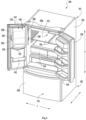
- FIGS. 1 and 2 provide perspective views of a refrigerator appliance 100 according to example embodiments of the present disclosure.
- FIG. 1 provides a pair of refrigerator doors 128 in a closed position
- FIG. 2 provides refrigerator doors 128 in an open position.
- Refrigerator appliance 100 includes a cabinet or housing 120 that extends between a top 101 and a bottom 102 along a vertical direction V.
- Cabinet 120 also extends along a lateral direction L and a transverse direction T, each of the vertical direction V, lateral direction L, and transverse direction T being mutually perpendicular to one another.
- Cabinet 120 defines one or more chilled chambers for receipt of food items for storage.
- cabinet 120 defines a fresh food chamber 122 positioned at or adjacent top 101 of cabinet 120 and a freezer chamber 124 arranged at or adjacent bottom 102 of cabinet 120.
- refrigerator appliance 100 is generally referred to as a bottom mount refrigerator.
- various storage components are mounted within fresh food chamber 122 to facilitate storage of food items therein, as will be understood by those skilled in the art.
- the storage components may include storage bins 192, drawers 194, and shelves 196 that are mounted within fresh food chamber 122.
- Storage bins 192, drawers 194, and shelves 196 are configured for receipt of food items (e.g., beverages or solid food items) and may assist with organizing such food items.
- drawers 194 can receive fresh food items (e.g., vegetables, fruits, or cheeses) and increase the useful life of such fresh food items.
- Refrigerator doors 128 are rotatably hinged to an edge of cabinet 120 for selectively accessing fresh food chamber 122.
- a freezer door 130 is arranged below refrigerator doors 128 for selectively accessing freezer chamber 124.
- Freezer door 130 may be coupled to a freezer drawer (not shown) slidably mounted within freezer chamber 124. Refrigerator doors 128 and freezer door 130 are shown in the closed configuration in FIG. 1 .
- refrigerator appliance 100 includes a dispensing assembly 140 for dispensing liquid water or ice.
- Dispensing assembly 140 includes a dispenser 142 positioned on or mounted to an exterior portion of refrigerator appliance 100 (e.g., on one of doors 128).
- Dispenser 142 includes a discharging outlet 144 for accessing ice and liquid water.
- An actuating mechanism 146 shown as a paddle, is mounted below discharging outlet 144 for operating dispenser 142.
- another suitable actuator may be used to operate dispenser 142.
- dispenser 142 can include a sensor (such as an ultrasonic sensor) or a button rather than the paddle.
- a user interface panel 148 is provided for controlling the mode of operation.
- user interface panel 148 includes a plurality of user inputs (not labeled), such as a water dispensing button and an ice-dispensing button, for selecting a desired mode of operation such as crushed or non-crushed ice.
- Discharging outlet 144 and actuating mechanism 146 are an external part of dispenser 142 and are mounted in a dispenser recess 150, as will be described in greater detail below.
- dispenser recess 150 defines a transverse opening 151 that extends in the vertical direction V from a top recess end 152 to a bottom recess end 154, as well as in the lateral direction L from a first recess side 156 to a second recess side 158.
- dispenser recess 150 is positioned at a predetermined elevation convenient for a user to access ice or water and enabling the user to access ice without the need to bend-over and without the need to open doors 128.
- dispenser recess 150 is positioned at a level that approximates the chest level of a user.
- refrigerator appliance 100 includes an ice-making assembly 160 in communication (e.g., physical communication, fluid communication, etc.) with dispensing assembly 140.
- ice-making assembly 160 in communication (e.g., physical communication, fluid communication, etc.) with dispensing assembly 140.
- an ice storage bin 202 may be mounted above discharging outlet 144 to direct ice thereto.
- door 128 defines a bin opening 204 through an external panel thereof to receive the ice storage bin 202 in the closed position.
- a bin compartment 206 extending from the bin opening 204 may be defined within the corresponding door 128 to further receive and house the ice storage bin 202 in the closed position.
- ice-making assembly 160 includes an icemaker 208 that is generally received within at least one chilled chamber (e.g., fresh food chamber 122), such as when the corresponding door 128 is in the closed position.
- icemaker 208 may be attached (e.g., directly attached) to one of doors 128.
- icemaker 208 may be directly attached to cabinet 120 and fixed within a chilled chamber (e.g., rearward of door 128, as illustrated in phantom lines in FIG. 2 ).
- At least one door 128 includes a door liner 132 defining a sub-compartment (e.g., icebox compartment 162).Icebox compartment 162 extends into fresh food chamber 122 when door 128 is in the closed position. Moreover, although icebox compartment 162 is shown in door 128, alterative embodiments may include an icebox compartment 162 fixed within fresh food chamber 122.
- ice may be supplied to dispenser recess 150 from a portion of ice-making assembly 160 in icebox compartment 162 on a back side of refrigerator door 128.
- chilled air from a sealed system of refrigerator appliance 100 may be directed into ice-making assembly 160 in order to cool components of ice-making assembly 160.
- an evaporator 178 e.g., positioned at or within fresh food chamber 122 or freezer chamber 1214 is configured for generating cooled or chilled air.
- a supply conduit 180 e.g., defined by or positioned within housing 120 extends between evaporator 178 and components of ice-making assembly 160 in order to cool components of ice-making assembly 160 and assist ice formation by ice-making assembly 160.
- ice-making assembly 160 during operation of ice-making assembly 160, chilled air from the sealed system cools components of ice-making assembly 160 to or below a freezing temperature of liquid water.
- ice-making assembly 160 may be an air cooled ice-making assembly.
- liquid water generated during melting of ice cubes in ice storage bin 202 is directed out of ice storage bin 202.
- liquid water from melted ice cubes may be directed to an evaporation pan 172.
- Evaporation pan 172 is positioned within a mechanical compartment 170 defined by housing 120 (e.g., at bottom portion 102 of housing 120).
- a condenser 174 of the sealed system can be positioned, for example, directly, above and adjacent evaporation pan 172. Heat from condenser 174 can assist with evaporation of liquid water in evaporation pan 172.
- a fan 176 configured for cooling condenser 174 can also direct a flow air across or into evaporation pan 172.
- fan 176 can be positioned above and adjacent evaporation pan 172.
- Evaporation pan 172 may be sized and shaped for facilitating evaporation of liquid water therein.
- evaporation pan 172 may be open topped and extend across about a width or a depth of housing 120.
- an access door 166 is hinged to refrigerator door 128. Access door 166 may permit selective access to sub-compartment 162. Any manner of suitable latch 168 may further be configured with sub-compartment 162 to maintain access door 166 in a closed position. As an example, latch 168 may be actuated by a consumer in order to open access door 166 for providing access into sub-compartment 162. Access door 166 can also assist with insulating sub-compartment 162.
- operation of the refrigerator appliance 100 can be regulated by a controller 190 that is operatively coupled to user interface panel 148 or various other components.
- User interface panel 148 provides selections for user manipulation of the operation of refrigerator appliance 100, such as selections between whole or crushed ice, chilled water, or other various options.
- controller 190 may operate various components of the refrigerator appliance 100.
- Controller 190 may include a memory and one or more microprocessors, CPUs or the like, such as general or special purpose microprocessors operable to execute programming instructions or micro-control code associated with operation of refrigerator appliance 100.
- the memory may represent random access memory such as DRAM, or read only memory such as ROM or FLASH.
- the processor executes programming instructions stored in memory.
- the memory may be a separate component from the processor or may be included onboard within the processor.
- controller 190 may be constructed without using a microprocessor (e.g., using a combination of discrete analog or digital logic circuitry-such as switches, amplifiers, integrators, comparators, flip-flops, AND gates, and the like) to perform control functionality instead of relying upon software.
- Controller 190 may be positioned in a variety of locations throughout refrigerator appliance 100. In the illustrated embodiment, controller 190 is located adjacent to or on user interface panel 148. In other embodiments, controller 190 may be positioned at another suitable location within refrigerator appliance 100, such as for example within a fresh food chamber, a freezer door, etc. Input/output ("I/O") signals may be routed between controller 190 and various operational components of refrigerator appliance 100. For example, user interface panel 148 may be in operable communication (e.g., electrical communication) with controller 190 via one or more signal lines or shared communication busses.
- I/O Input/output
- Controller 190 may be operatively coupled with the various components of dispensing assembly 140 and may control operation of the various components.
- the various valves, switches, etc. may be actuatable based on commands from controller 190.
- interface panel 148 may additionally be operatively coupled (e.g., via electrical or wireless communication) with controller 190.
- the various operations may occur based on user input or automatically through controller 190 instruction.
- FIGS. 3 through 7 various views are provided of ice storage bin 202 and a corresponding door 128 within which ice storage bin 202 may be received.
- FIGS. 3 through 5 provide schematic views of ice storage bin 202 in relation to door 128.
- FIG. 6 provides a perspective view of ice storage bin 202 in isolation.
- FIG. 7 provides a perspective view that includes a portion of door 128 when ice storage bin 202 has been removed from bin compartment 206.
- ice storage bin 202 generally includes a plurality of walls defining a storage cavity 214.
- ice storage bin 202 may include one or more sidewalls 210 and a base wall 212, which may together define storage cavity 214.
- the sidewalls 210 include a front wall 220, rear wall 222, and a pair of intermediate walls 224 therebetween Together, the sidewalls 210 define an opening perimeter 216 at a top portion (e.g., vertical extreme opposite the base wall 212) of container ice storage bin 202.
- opening perimeter 216 may permit access to storage cavity 214 (e.g., to add or remove ice therein).
- the storage cavity 214 may be in communication (e.g., selective physical communication, fluid communication, etc.) with icemaker 208 to receive ice therefrom.
- icemaker 208 is mounted above bin opening 204 or bin compartment 206 along the vertical direction V.
- icemaker 208 may be positioned above storage bin 202 (e.g., over the opening perimeter 216).
- ice storage bin 202 is 202ia slidably mounted to door 128 to move through bin opening 204 between a mounted position (e.g., FIG. 4 ) and a removed position (e.g., FIG. 5 ).
- the mounted position may restrict user access to storage cavity 214 (e.g., through the opening perimeter 216) while the removed position may permit access to storage cavity 214 (e.g., through the opening perimeter 216).
- the mounted position at least a portion of ice storage bin 202 is received within bin compartment 206.
- storage cavity 214 is in communication (e.g., fluid communication) with icemaker 208, such that ice cubes can be received therefrom.
- storage cavity 214 may be offset or out of alignment with bin compartment 206.
- ice storage bin 202 and storage cavity 214 may be completely removed from bin compartment 206 or door 128.
- ice storage bin 202 may move independently from door 128 and the rest of refrigerator appliance 100.
- the removed position may thus permit a user to place ice storage bin 202 on a counter or dump ice directly therefrom (e.g., through opening perimeter 216).
- ice storage bin 202 may be accessed without exposing fresh food chamber 122 ( FIG. 2 ) to ambient air.
- storage bin 202 is slidable along a direction perpendicular to the vertical direction V, such as along the transverse direction T (e.g., as defined when the corresponding door 128 is in the closed position). In moving between the mounted position and the removed position, ice storage bin 202 may slide linearly along the transverse direction T.
- ice storage bin 202 includes at least one insulated sidewall 230.
- Insulated sidewall 230 is provided as front wall 220 (e.g., adjacent to an external panel of door 128 in a mounted position).
- insulated sidewall 230 may define a wall thickness (e.g., in the transverse direction T or radially outward from storage cavity 214) that is greater than the wall thickness of the other sidewalls 210 or base wall 212.
- a separate insulator e.g., a suitable rigid or foam insulation
- insulated sidewall 230 When ice storage bin 202 is inserted into bin opening 204 and bin compartment 206 (e.g., in the mounted position), the insulated sidewall 230 is positioned across bin opening 204. A radial edge 232 of insulated sidewall 230 extends outward from bin opening 204. In other words, insulated sidewall 230 defines a footprint (e.g., lateral width or vertical height) greater than an outer perimeter or periphery 234 of bin opening 204. An inner surface 236 of insulated sidewall 230 contacts (e.g., directly or indirectly) a portion of door 128 surrounding bin opening 204.
- a sealing gasket 238 may be attached to the inner surface 236 of insulated sidewall 230. In a mounted position, sealing gasket 238 may be positioned about the periphery 234 of bin opening 204 (e.g., to restrict heat transfer between bin compartment 206 and the ambient environment).
- front wall 220 includes an unobstructed handle 240.
- unobstructed handle 240 may be readily grasped (e.g., by a user) and free from a cover restricting access to unobstructed handle 240.
- front wall 220 may provide unobstructed handle 240 directly in front of storage cavity 214 (e.g., along the transverse direction T).
- unobstructed handle 240 may extend perpendicular to the direction of movement for ice storage bin 202.
- unobstructed handle 240 may extend along the vertical direction V (e.g., such that the vertical dimension is greater than a dimension in a lateral direction L or transverse direction T, as shown).
- a mechanical latch 242 is provided on front wall 220 to selectively engage a corresponding catch or recess 244 defined within door 128. For instance, in the mounted position, mechanical latch 242 may be received within recess 244 to secure ice storage bin 202 in the mounted position.
- a trigger e.g., movably mounted on unobstructed handle 240 may be provided to selectively release mechanical latch 242.
- storage cavity 214 is in communication (e.g., fluid communication) with the dispensing assembly 140 in the mounted position, such as to direct ice to the ice delivery passage 246 (e.g., via a base aperture 218 defined through ice storage bin 202 from storage cavity 214).
- ice storage bin 202 is mountable above dispenser recess 150.
- bin opening 204 is defined above dispenser recess 150.
- dispensing assembly 140 generally defines an ice delivery passage 246 in communication with storage bin 202 (e.g., in the mounted position).
- dispensing assembly 140 may include a dispenser conduit 248 defining an ice delivery passage 246 through door 128.
- ice delivery passage 246 extends between an inlet 260 and an outlet 262.
- Inlet 260 of ice delivery passage 246 is positioned at or adjacent ice storage bin 202 (e.g., beneath base aperture 218), and outlet 262 of ice delivery passage 246 is positioned at or adjacent a top portion of dispenser recess 150 (e.g., such that outlet 262 forms or corresponds to discharging outlet 144- FIG. 1 ).
- Inlet 260 of ice delivery passage 246 may be positioned above outlet 262 of ice delivery passage 246 along the vertical direction V (e.g., such that gravity urges ice nuggets or cubes through ice delivery passage 246 to outlet 262). For instance, ice may be generally urged through base aperture 218. From base aperture 218, ice may thus flow to ice delivery passage 246 after passing through inlet 260.
- Ice storage bin 202 may include one or more features for directing or motivating ice within storage cavity 214.
- a driven rod 264 is provided on or within ice storage bin 202.
- driven rod 264 may extend along a rotation axis A within storage cavity 214.
- a plurality of ice crusher blades 266, 268 are positioned within ice storage bin 202.
- multiple ice crusher blades 266, 268 may be positioned on or around driven rod 264.
- the plurality of blades 266, 268 includes at least one rotary blade 266 and at least one stationary blade 268.
- Rotary blades may be fixed to driven rod 264 (e.g., to rotate therewith) while stationary blades 268 may be fixed to another portion of bin 202 (e.g., one or more sidewalls 210 or base wall 212) such that rotation of driven rod 264 does not rotate stationary blades 268.
- the rotary blades 266 may be distributed on a rotation axis A or driven rod 264 such that the rotary blades 266 are staggered along the driven rod 264.
- the stationary blade(s) 268 may be staggered or positioned between rotary blades 266. During use, a single rotary blade 266 may thus crush ice against the stationary blade(s) 268 as ice passes to the base aperture 218.
- a rotatable agitator paddle 270 may be fixed to driven rod 264 to guide or move ice through storage cavity 214.
- agitator paddle 270 may be positioned opposite from ice blades 266, 268 on driven rod 264 (e.g., at opposite ends of rotation axis A).
- blades 266, 268 and rotatable agitator paddle 270 may rotate about driven rod 264, in unison, such that rotary blades 266 and agitator paddle 270 rotate at about the same angular velocity.
- a motor 272 is provided on or within door 128 to selectively engage a portion of ice storage bin 202.
- motor 272 may be mounted to door 128, such as at a rear portion of bin compartment 206.
- motor 272 may be fixed to a portion of liner wall 132 or access door 166 ( FIG. 2 ) on or within bin compartment 206.
- motor 272 may be operably coupled (e.g., in mechanical communication with) a portion of ice storage bin 202.
- motor 272 may be coupled to driven rod 264.
- motor 272 includes an adapter key 274 to selectively engage driven rod 264.
- adapter key 274 may mechanically couple with driven rod 264 in a horizontal connection beside rear wall 222.
- bin motor 272 may motivate rotation of adapter key 274 and driven rod 264 about the rotation axis A, which in turn motivates rotation of blades 266, 268 or agitator paddle 270.
- the horizontal connection between motor 272 and driven rod 264 may permit ice storage bin 202 to slide horizontally (i.e., perpendicular to the vertical direction V) into attachment with refrigerator appliance 100 ( FIG. 2 ) without requiring any vertical movement or motion from ice storage bin 202.
- a user may attach or remove storage ice storage bin 202 from refrigerator appliance 100 without lifting ice storage bin 202 up and over bin motor 272.
Landscapes
- Engineering & Computer Science (AREA)
- Physics & Mathematics (AREA)
- Mechanical Engineering (AREA)
- Thermal Sciences (AREA)
- General Engineering & Computer Science (AREA)
- Chemical & Material Sciences (AREA)
- Combustion & Propulsion (AREA)
- Cold Air Circulating Systems And Constructional Details In Refrigerators (AREA)
- Refrigerator Housings (AREA)
- Devices That Are Associated With Refrigeration Equipment (AREA)
Claims (10)
- Kühlgerät (100), umfassend:ein Gehäuse (120), das eine Kühlkammer definiert;eine Tür (128), die einen Behälter (204) und eine Ausgabeaussparung (150) definiert, wobei die Tür (128) drehbar an dem Gehäuse (120) angelenkt ist, um zwischen einer geschlossenen Position, die den Zugang zu der gekühlten Kammer einschränkt, und einer offenen Position, die den Zugang zu der gekühlten Kammer ermöglicht, zu drehen;eine Ausgabeanordnung (140), die in der Ausgabeaussparung (150) positioniert ist und einen Eisausgabedurchgang (246) definiert;einen Eisbereiter (208) in selektiver Verbindung mit der Ausgabeanordnung (140); undeinen Eisaufbewahrungsbehälter (202), der einen Aufbewahrungshohlraum (214) definiert, wobei der Eisaufbewahrungsbehälter (202) verschiebbar an der Tür (128) montiert ist, um sich durch die Behälteröffnung (204) zwischen einer montierten Position und einer abgenommenen Position zu bewegen, der Eisaufbewahrungsbehälter (202) umfassend eine isolierte Vorderwand (220), die in der montierten Position an der Behälteröffnung (204) positioniert ist, wobei der Aufbewahrungshohlraum (214) in der montierten Position mit dem Eisbereiter (208) in Verbindung ist, um Eis davon aufzunehmen, wobei der Aufbewahrungshohlraum (214) in der montierten Position mit der Ausgabeanordnung (140) in Verbindung ist, um Eis zu dem Eisausgabedurchgang (246) zu leiten;dadurch gekennzeichnet, dass der Eisaufbewahrungsbehälter (202) mindestens eine isolierte Seitenwand (230) umfasst, wobei die isolierte Seitenwand (230) als die isolierte Vorderwand (220) bereitgestellt ist, die isolierte Seitenwand (230) eine Aufstandsfläche definiert, die größer ist als ein Umfang (234) der Behälteröffnung (204), eine Innenfläche (236) der isolierten Seitenwand (230) einen Abschnitt der Tür (128) berührt, der die Behälteröffnung (204) umgibt.
- Kühlgerät nach Anspruch 1, wobei der Eisbereiter (208) in vertikaler Richtung oberhalb des Eisaufbewahrungsbehälters (202) montiert ist.
- Kühlgerät nach Anspruch 1, wobei die Behälteröffnung (204) oberhalb der Ausgabeaussparung (150) in vertikaler Richtung definiert ist.
- Kühlgerät nach Anspruch 1, wobei die isolierte Vorderwand (220) einen ungehinderten Griff (240) beinhaltet, der vor dem Aufbewahrungshohlraum (214) positioniert ist.
- Kühlgerät nach Anspruch 1, wobei der Eisaufbewahrungsbehälter (202) ferner eine Dichtung (238) umfasst, die an einer Innenfläche der isolierten Vorderwand (220) angebracht ist, wobei die Dichtung (238) in der montierten Position um den Umfang (234) der Behälteröffnung (204) positioniert ist.
- Kühlgerät nach Anspruch 1, ferner umfassend einen Motor (272), der an der Tür (128) montiert und in der montierten Position funktionsfähig mit dem Eisaufbewahrungsbehälter (202) gekoppelt ist.
- Kühlgerät nach Anspruch 6, wobei der Eisaufbewahrungsbehälter (202) eine angetriebene Stange (264) umfasst, die sich entlang einer Drehachse innerhalb des Aufbewahrungshohlraums (214) erstreckt, wobei die angetriebene Stange (264) selektiv mit dem Motor (272) gekoppelt ist.
- Kühlgerät nach Anspruch 7, wobei der Eisaufbewahrungsbehälter (202) ferner eine Vielzahl von Eiszerkleinerungsklingen (266, 268) umfasst, die an der angetriebenen Stange (264) befestigt sind, um damit um die Drehachse zu drehen, und der Eisaufbewahrungsbehälter (202) ferner ein Rührpaddel (270) umfasst, das an der angetriebenen Stange (264) befestigt ist, um damit um die Drehachse zu drehen.
- Kühlgerät nach Anspruch 1, wobei der Eisbereiter (208) direkt an der Tür (128) montiert ist, oder der Eisbereiter (208) direkt an dem Gehäuse (120) montiert ist.
- Kühlgerät nach Anspruch 1, wobei das Kühlgerät ferner Folgendes umfasst:
einen Motor (272), der an der Tür montiert und in der montierten Position funktionsfähig mit dem Eisaufbewahrungsbehälter gekoppelt ist, wobei der Eisaufbewahrungsbehälter eine angetriebene Stange (264) umfasst, die sich entlang einer Drehachse innerhalb des Aufbewahrungshohlraums erstreckt, wobei die angetriebene Stange (264) selektiv mit dem Motor (272) gekoppelt ist,
wobei der Motor (272) eine Passfeder (274) beinhaltet, um die angetriebene Stange (264) selektiv einzugreifen, wenn der Eisaufbewahrungsbehälter (202) in der montierten Position ist, wobei die Passfeder (274) in einer horizontalen Verbindung mechanisch mit der angetriebenen Stange (264) koppelt.
Applications Claiming Priority (2)
| Application Number | Priority Date | Filing Date | Title |
|---|---|---|---|
| US16/412,846 US11009277B2 (en) | 2019-05-15 | 2019-05-15 | Refrigator applicances having a removable ice storage bin |
| PCT/CN2020/089303 WO2020228622A1 (zh) | 2019-05-15 | 2020-05-09 | 具有可拆卸储冰盒的制冷电器 |
Publications (3)
| Publication Number | Publication Date |
|---|---|
| EP3971496A1 EP3971496A1 (de) | 2022-03-23 |
| EP3971496A4 EP3971496A4 (de) | 2022-06-22 |
| EP3971496B1 true EP3971496B1 (de) | 2024-07-31 |
Family
ID=73228343
Family Applications (1)
| Application Number | Title | Priority Date | Filing Date |
|---|---|---|---|
| EP20806153.1A Active EP3971496B1 (de) | 2019-05-15 | 2020-05-09 | Kühlgeräte mit entfernbarem eisaufbewahrungsbehälter |
Country Status (4)
| Country | Link |
|---|---|
| US (1) | US11009277B2 (de) |
| EP (1) | EP3971496B1 (de) |
| CN (1) | CN113825963B (de) |
| WO (1) | WO2020228622A1 (de) |
Families Citing this family (3)
| Publication number | Priority date | Publication date | Assignee | Title |
|---|---|---|---|---|
| US11774172B2 (en) * | 2021-06-24 | 2023-10-03 | Electrolux Home Products, Inc. | Drawer in a refrigerator door |
| US11918009B2 (en) * | 2022-04-15 | 2024-03-05 | Haier Us Appliance Solutions, Inc. | Refrigerator appliance having one or more incorporated features for making ice cream |
| US20250116452A1 (en) * | 2023-10-04 | 2025-04-10 | Haier Us Appliance Solutions, Inc. | Drawer in door assembly for a refrigerator appliance |
Citations (1)
| Publication number | Priority date | Publication date | Assignee | Title |
|---|---|---|---|---|
| JPS489465U (de) * | 1971-06-11 | 1973-02-02 |
Family Cites Families (16)
| Publication number | Priority date | Publication date | Assignee | Title |
|---|---|---|---|---|
| US3744270A (en) * | 1971-11-01 | 1973-07-10 | Westinghouse Electric Corp | Ice maker and ice service drawer arrangement |
| US4087140A (en) * | 1977-04-14 | 1978-05-02 | Whirlpool Corporation | Magnetic latch - movable ice receptacle |
| US4269039A (en) * | 1979-09-13 | 1981-05-26 | Whirlpool Corporation | Ice receptacle support |
| KR101264931B1 (ko) * | 2006-08-17 | 2013-05-15 | 엘지전자 주식회사 | 냉장고의 제빙수단 |
| KR100780836B1 (ko) * | 2006-09-12 | 2007-11-30 | 엘지전자 주식회사 | 냉장고용 아이스뱅크 고정장치 및 이를 포함하는 냉장고 |
| KR101085295B1 (ko) | 2007-09-12 | 2011-11-22 | 엘지전자 주식회사 | 냉장고 |
| US8312735B2 (en) | 2008-03-12 | 2012-11-20 | Whirlpool Corporation | External tilt bucket for an appliance door |
| KR20120040891A (ko) | 2010-10-20 | 2012-04-30 | 삼성전자주식회사 | 냉장고 |
| CN102226617B (zh) * | 2011-05-31 | 2013-01-30 | 合肥美的荣事达电冰箱有限公司 | 一种冰箱 |
| US9476634B2 (en) * | 2013-03-25 | 2016-10-25 | Lg Electronics Inc. | Refrigerator |
| KR102236751B1 (ko) * | 2014-08-18 | 2021-04-06 | 삼성전자주식회사 | 냉장고 |
| CN105783371A (zh) * | 2014-12-25 | 2016-07-20 | 海信容声(广东)冰箱有限公司 | 一种冰箱 |
| KR102756990B1 (ko) * | 2016-12-08 | 2025-01-21 | 삼성전자주식회사 | 냉장고 |
| CN106918173A (zh) * | 2017-02-13 | 2017-07-04 | 合肥华凌股份有限公司 | 一种防冰块冻结的储冰盒、冰块防冻结方法和冰箱 |
| US10260790B2 (en) | 2017-06-16 | 2019-04-16 | Haier US Applicance Solutions, Inc. | Refrigerator appliance having an ice storage bin |
| KR102442067B1 (ko) * | 2017-09-29 | 2022-09-13 | 삼성전자주식회사 | 냉장고 |
-
2019
- 2019-05-15 US US16/412,846 patent/US11009277B2/en active Active
-
2020
- 2020-05-09 CN CN202080034526.5A patent/CN113825963B/zh active Active
- 2020-05-09 WO PCT/CN2020/089303 patent/WO2020228622A1/zh not_active Ceased
- 2020-05-09 EP EP20806153.1A patent/EP3971496B1/de active Active
Patent Citations (1)
| Publication number | Priority date | Publication date | Assignee | Title |
|---|---|---|---|---|
| JPS489465U (de) * | 1971-06-11 | 1973-02-02 |
Also Published As
| Publication number | Publication date |
|---|---|
| CN113825963A (zh) | 2021-12-21 |
| WO2020228622A1 (zh) | 2020-11-19 |
| US20200363115A1 (en) | 2020-11-19 |
| EP3971496A1 (de) | 2022-03-23 |
| CN113825963B (zh) | 2023-02-17 |
| EP3971496A4 (de) | 2022-06-22 |
| US11009277B2 (en) | 2021-05-18 |
Similar Documents
| Publication | Publication Date | Title |
|---|---|---|
| US10240842B2 (en) | Ice making appliance and apparatus | |
| EP3343139B1 (de) | Kühlschrank mit eisbereiter | |
| CA2793581C (en) | Ice dispenser with crusher for a refrigerator appliance | |
| EP1517102B1 (de) | Kühlschrank mit Eiserzeuger | |
| US10352610B2 (en) | Refrigerator appliance | |
| EP1653176B1 (de) | Eisherstellung und Abgabesystem | |
| US8794023B2 (en) | Ice dispenser with crusher for a refrigerator appliance | |
| EP1657510B1 (de) | Eisherstellung und Abgabesystem | |
| US20160282028A1 (en) | Ice maker for french door bottom mount refrigerator | |
| US11598566B2 (en) | Revolving ice maker | |
| EP3971496B1 (de) | Kühlgeräte mit entfernbarem eisaufbewahrungsbehälter | |
| US20170332658A1 (en) | Refrigerator Appliance and Frozen Beverage Unit | |
| US11629902B2 (en) | Refrigerator appliance having an ice storage bin | |
| KR20160136612A (ko) | 냉장고 | |
| EP4019865A1 (de) | Kühlgerät, das mehrere kühlfächer in fluidverbindung miteinander aufweist | |
| US11137189B1 (en) | Ice dispenser assembly for a refrigerator appliance | |
| EP2021706B1 (de) | Kühlvorrichtung | |
| US11859887B2 (en) | Ice making assembly and refrigerator appliance | |
| US11918009B2 (en) | Refrigerator appliance having one or more incorporated features for making ice cream | |
| AU2018405004B2 (en) | Refrigerator appliance and ice maker apparatus | |
| EP4102157A1 (de) | Eisspeicherbox, die eine kickplatte für ein kühlgerät aufweist | |
| US11262116B2 (en) | Refrigerator appliance having a removable ice storage bin | |
| US11732945B2 (en) | Ice making assembly and refrigerator appliance | |
| WO2021223149A1 (en) | Ice bucket agitator and refrigerator appliance |
Legal Events
| Date | Code | Title | Description |
|---|---|---|---|
| STAA | Information on the status of an ep patent application or granted ep patent |
Free format text: STATUS: THE INTERNATIONAL PUBLICATION HAS BEEN MADE |
|
| PUAI | Public reference made under article 153(3) epc to a published international application that has entered the european phase |
Free format text: ORIGINAL CODE: 0009012 |
|
| STAA | Information on the status of an ep patent application or granted ep patent |
Free format text: STATUS: REQUEST FOR EXAMINATION WAS MADE |
|
| 17P | Request for examination filed |
Effective date: 20211115 |
|
| AK | Designated contracting states |
Kind code of ref document: A1 Designated state(s): AL AT BE BG CH CY CZ DE DK EE ES FI FR GB GR HR HU IE IS IT LI LT LU LV MC MK MT NL NO PL PT RO RS SE SI SK SM TR |
|
| A4 | Supplementary search report drawn up and despatched |
Effective date: 20220525 |
|
| RIC1 | Information provided on ipc code assigned before grant |
Ipc: F25D 25/02 20060101ALI20220519BHEP Ipc: F25D 23/04 20060101ALI20220519BHEP Ipc: F25C 5/20 20180101AFI20220519BHEP |
|
| DAV | Request for validation of the european patent (deleted) | ||
| DAX | Request for extension of the european patent (deleted) | ||
| REG | Reference to a national code |
Ref country code: DE Ref legal event code: R079 Free format text: PREVIOUS MAIN CLASS: F25C0005000000 Ipc: F25C0005200000 Ref document number: 602020034967 Country of ref document: DE |
|
| GRAP | Despatch of communication of intention to grant a patent |
Free format text: ORIGINAL CODE: EPIDOSNIGR1 |
|
| STAA | Information on the status of an ep patent application or granted ep patent |
Free format text: STATUS: GRANT OF PATENT IS INTENDED |
|
| RIC1 | Information provided on ipc code assigned before grant |
Ipc: F25D 23/02 20060101ALN20240214BHEP Ipc: F25D 25/02 20060101ALI20240214BHEP Ipc: F25D 23/04 20060101ALI20240214BHEP Ipc: F25C 5/20 20180101AFI20240214BHEP |
|
| INTG | Intention to grant announced |
Effective date: 20240229 |
|
| GRAS | Grant fee paid |
Free format text: ORIGINAL CODE: EPIDOSNIGR3 |
|
| GRAA | (expected) grant |
Free format text: ORIGINAL CODE: 0009210 |
|
| STAA | Information on the status of an ep patent application or granted ep patent |
Free format text: STATUS: THE PATENT HAS BEEN GRANTED |
|
| AK | Designated contracting states |
Kind code of ref document: B1 Designated state(s): AL AT BE BG CH CY CZ DE DK EE ES FI FR GB GR HR HU IE IS IT LI LT LU LV MC MK MT NL NO PL PT RO RS SE SI SK SM TR |
|
| REG | Reference to a national code |
Ref country code: CH Ref legal event code: EP Ref country code: GB Ref legal event code: FG4D |
|
| REG | Reference to a national code |
Ref country code: DE Ref legal event code: R096 Ref document number: 602020034967 Country of ref document: DE |
|
| REG | Reference to a national code |
Ref country code: IE Ref legal event code: FG4D |
|
| REG | Reference to a national code |
Ref country code: LT Ref legal event code: MG9D |
|
| REG | Reference to a national code |
Ref country code: NL Ref legal event code: MP Effective date: 20240731 |
|
| PG25 | Lapsed in a contracting state [announced via postgrant information from national office to epo] |
Ref country code: PT Free format text: LAPSE BECAUSE OF FAILURE TO SUBMIT A TRANSLATION OF THE DESCRIPTION OR TO PAY THE FEE WITHIN THE PRESCRIBED TIME-LIMIT Effective date: 20241202 |
|
| REG | Reference to a national code |
Ref country code: AT Ref legal event code: MK05 Ref document number: 1708794 Country of ref document: AT Kind code of ref document: T Effective date: 20240731 |
|
| PG25 | Lapsed in a contracting state [announced via postgrant information from national office to epo] |
Ref country code: PT Free format text: LAPSE BECAUSE OF FAILURE TO SUBMIT A TRANSLATION OF THE DESCRIPTION OR TO PAY THE FEE WITHIN THE PRESCRIBED TIME-LIMIT Effective date: 20241202 |
|
| PG25 | Lapsed in a contracting state [announced via postgrant information from national office to epo] |
Ref country code: NO Free format text: LAPSE BECAUSE OF FAILURE TO SUBMIT A TRANSLATION OF THE DESCRIPTION OR TO PAY THE FEE WITHIN THE PRESCRIBED TIME-LIMIT Effective date: 20241031 |
|
| PG25 | Lapsed in a contracting state [announced via postgrant information from national office to epo] |
Ref country code: FI Free format text: LAPSE BECAUSE OF FAILURE TO SUBMIT A TRANSLATION OF THE DESCRIPTION OR TO PAY THE FEE WITHIN THE PRESCRIBED TIME-LIMIT Effective date: 20240731 Ref country code: NL Free format text: LAPSE BECAUSE OF FAILURE TO SUBMIT A TRANSLATION OF THE DESCRIPTION OR TO PAY THE FEE WITHIN THE PRESCRIBED TIME-LIMIT Effective date: 20240731 Ref country code: PL Free format text: LAPSE BECAUSE OF FAILURE TO SUBMIT A TRANSLATION OF THE DESCRIPTION OR TO PAY THE FEE WITHIN THE PRESCRIBED TIME-LIMIT Effective date: 20240731 Ref country code: GR Free format text: LAPSE BECAUSE OF FAILURE TO SUBMIT A TRANSLATION OF THE DESCRIPTION OR TO PAY THE FEE WITHIN THE PRESCRIBED TIME-LIMIT Effective date: 20241101 |
|
| PG25 | Lapsed in a contracting state [announced via postgrant information from national office to epo] |
Ref country code: BG Free format text: LAPSE BECAUSE OF FAILURE TO SUBMIT A TRANSLATION OF THE DESCRIPTION OR TO PAY THE FEE WITHIN THE PRESCRIBED TIME-LIMIT Effective date: 20240731 |
|
| PG25 | Lapsed in a contracting state [announced via postgrant information from national office to epo] |
Ref country code: LV Free format text: LAPSE BECAUSE OF FAILURE TO SUBMIT A TRANSLATION OF THE DESCRIPTION OR TO PAY THE FEE WITHIN THE PRESCRIBED TIME-LIMIT Effective date: 20240731 |
|
| PG25 | Lapsed in a contracting state [announced via postgrant information from national office to epo] |
Ref country code: AT Free format text: LAPSE BECAUSE OF FAILURE TO SUBMIT A TRANSLATION OF THE DESCRIPTION OR TO PAY THE FEE WITHIN THE PRESCRIBED TIME-LIMIT Effective date: 20240731 Ref country code: IS Free format text: LAPSE BECAUSE OF FAILURE TO SUBMIT A TRANSLATION OF THE DESCRIPTION OR TO PAY THE FEE WITHIN THE PRESCRIBED TIME-LIMIT Effective date: 20241130 |
|
| PG25 | Lapsed in a contracting state [announced via postgrant information from national office to epo] |
Ref country code: HR Free format text: LAPSE BECAUSE OF FAILURE TO SUBMIT A TRANSLATION OF THE DESCRIPTION OR TO PAY THE FEE WITHIN THE PRESCRIBED TIME-LIMIT Effective date: 20240731 |
|
| PG25 | Lapsed in a contracting state [announced via postgrant information from national office to epo] |
Ref country code: RS Free format text: LAPSE BECAUSE OF FAILURE TO SUBMIT A TRANSLATION OF THE DESCRIPTION OR TO PAY THE FEE WITHIN THE PRESCRIBED TIME-LIMIT Effective date: 20241031 Ref country code: ES Free format text: LAPSE BECAUSE OF FAILURE TO SUBMIT A TRANSLATION OF THE DESCRIPTION OR TO PAY THE FEE WITHIN THE PRESCRIBED TIME-LIMIT Effective date: 20240731 |
|
| PG25 | Lapsed in a contracting state [announced via postgrant information from national office to epo] |
Ref country code: RS Free format text: LAPSE BECAUSE OF FAILURE TO SUBMIT A TRANSLATION OF THE DESCRIPTION OR TO PAY THE FEE WITHIN THE PRESCRIBED TIME-LIMIT Effective date: 20241031 Ref country code: PL Free format text: LAPSE BECAUSE OF FAILURE TO SUBMIT A TRANSLATION OF THE DESCRIPTION OR TO PAY THE FEE WITHIN THE PRESCRIBED TIME-LIMIT Effective date: 20240731 Ref country code: NO Free format text: LAPSE BECAUSE OF FAILURE TO SUBMIT A TRANSLATION OF THE DESCRIPTION OR TO PAY THE FEE WITHIN THE PRESCRIBED TIME-LIMIT Effective date: 20241031 Ref country code: NL Free format text: LAPSE BECAUSE OF FAILURE TO SUBMIT A TRANSLATION OF THE DESCRIPTION OR TO PAY THE FEE WITHIN THE PRESCRIBED TIME-LIMIT Effective date: 20240731 Ref country code: LV Free format text: LAPSE BECAUSE OF FAILURE TO SUBMIT A TRANSLATION OF THE DESCRIPTION OR TO PAY THE FEE WITHIN THE PRESCRIBED TIME-LIMIT Effective date: 20240731 Ref country code: IS Free format text: LAPSE BECAUSE OF FAILURE TO SUBMIT A TRANSLATION OF THE DESCRIPTION OR TO PAY THE FEE WITHIN THE PRESCRIBED TIME-LIMIT Effective date: 20241130 Ref country code: HR Free format text: LAPSE BECAUSE OF FAILURE TO SUBMIT A TRANSLATION OF THE DESCRIPTION OR TO PAY THE FEE WITHIN THE PRESCRIBED TIME-LIMIT Effective date: 20240731 Ref country code: GR Free format text: LAPSE BECAUSE OF FAILURE TO SUBMIT A TRANSLATION OF THE DESCRIPTION OR TO PAY THE FEE WITHIN THE PRESCRIBED TIME-LIMIT Effective date: 20241101 Ref country code: FI Free format text: LAPSE BECAUSE OF FAILURE TO SUBMIT A TRANSLATION OF THE DESCRIPTION OR TO PAY THE FEE WITHIN THE PRESCRIBED TIME-LIMIT Effective date: 20240731 Ref country code: ES Free format text: LAPSE BECAUSE OF FAILURE TO SUBMIT A TRANSLATION OF THE DESCRIPTION OR TO PAY THE FEE WITHIN THE PRESCRIBED TIME-LIMIT Effective date: 20240731 Ref country code: BG Free format text: LAPSE BECAUSE OF FAILURE TO SUBMIT A TRANSLATION OF THE DESCRIPTION OR TO PAY THE FEE WITHIN THE PRESCRIBED TIME-LIMIT Effective date: 20240731 Ref country code: AT Free format text: LAPSE BECAUSE OF FAILURE TO SUBMIT A TRANSLATION OF THE DESCRIPTION OR TO PAY THE FEE WITHIN THE PRESCRIBED TIME-LIMIT Effective date: 20240731 |
|
| PG25 | Lapsed in a contracting state [announced via postgrant information from national office to epo] |
Ref country code: DK Free format text: LAPSE BECAUSE OF FAILURE TO SUBMIT A TRANSLATION OF THE DESCRIPTION OR TO PAY THE FEE WITHIN THE PRESCRIBED TIME-LIMIT Effective date: 20240731 Ref country code: SM Free format text: LAPSE BECAUSE OF FAILURE TO SUBMIT A TRANSLATION OF THE DESCRIPTION OR TO PAY THE FEE WITHIN THE PRESCRIBED TIME-LIMIT Effective date: 20240731 Ref country code: RO Free format text: LAPSE BECAUSE OF FAILURE TO SUBMIT A TRANSLATION OF THE DESCRIPTION OR TO PAY THE FEE WITHIN THE PRESCRIBED TIME-LIMIT Effective date: 20240731 |
|
| PG25 | Lapsed in a contracting state [announced via postgrant information from national office to epo] |
Ref country code: EE Free format text: LAPSE BECAUSE OF FAILURE TO SUBMIT A TRANSLATION OF THE DESCRIPTION OR TO PAY THE FEE WITHIN THE PRESCRIBED TIME-LIMIT Effective date: 20240731 |
|
| PG25 | Lapsed in a contracting state [announced via postgrant information from national office to epo] |
Ref country code: CZ Free format text: LAPSE BECAUSE OF FAILURE TO SUBMIT A TRANSLATION OF THE DESCRIPTION OR TO PAY THE FEE WITHIN THE PRESCRIBED TIME-LIMIT Effective date: 20240731 |
|
| PG25 | Lapsed in a contracting state [announced via postgrant information from national office to epo] |
Ref country code: IT Free format text: LAPSE BECAUSE OF FAILURE TO SUBMIT A TRANSLATION OF THE DESCRIPTION OR TO PAY THE FEE WITHIN THE PRESCRIBED TIME-LIMIT Effective date: 20240731 Ref country code: SK Free format text: LAPSE BECAUSE OF FAILURE TO SUBMIT A TRANSLATION OF THE DESCRIPTION OR TO PAY THE FEE WITHIN THE PRESCRIBED TIME-LIMIT Effective date: 20240731 |
|
| REG | Reference to a national code |
Ref country code: DE Ref legal event code: R097 Ref document number: 602020034967 Country of ref document: DE |
|
| PLBE | No opposition filed within time limit |
Free format text: ORIGINAL CODE: 0009261 |
|
| STAA | Information on the status of an ep patent application or granted ep patent |
Free format text: STATUS: NO OPPOSITION FILED WITHIN TIME LIMIT |
|
| 26N | No opposition filed |
Effective date: 20250501 |
|
| PGFP | Annual fee paid to national office [announced via postgrant information from national office to epo] |
Ref country code: DE Payment date: 20250513 Year of fee payment: 6 |
|
| PGFP | Annual fee paid to national office [announced via postgrant information from national office to epo] |
Ref country code: GB Payment date: 20250521 Year of fee payment: 6 |
|
| PGFP | Annual fee paid to national office [announced via postgrant information from national office to epo] |
Ref country code: FR Payment date: 20250530 Year of fee payment: 6 |
|
| PG25 | Lapsed in a contracting state [announced via postgrant information from national office to epo] |
Ref country code: SE Free format text: LAPSE BECAUSE OF FAILURE TO SUBMIT A TRANSLATION OF THE DESCRIPTION OR TO PAY THE FEE WITHIN THE PRESCRIBED TIME-LIMIT Effective date: 20240731 |
|
| REG | Reference to a national code |
Ref country code: CH Ref legal event code: H13 Free format text: ST27 STATUS EVENT CODE: U-0-0-H10-H13 (AS PROVIDED BY THE NATIONAL OFFICE) Effective date: 20251223 |
|
| PG25 | Lapsed in a contracting state [announced via postgrant information from national office to epo] |
Ref country code: LU Free format text: LAPSE BECAUSE OF NON-PAYMENT OF DUE FEES Effective date: 20250509 |
|
| PG25 | Lapsed in a contracting state [announced via postgrant information from national office to epo] |
Ref country code: CH Free format text: LAPSE BECAUSE OF NON-PAYMENT OF DUE FEES Effective date: 20250531 |
|
| PG25 | Lapsed in a contracting state [announced via postgrant information from national office to epo] |
Ref country code: MC Free format text: LAPSE BECAUSE OF FAILURE TO SUBMIT A TRANSLATION OF THE DESCRIPTION OR TO PAY THE FEE WITHIN THE PRESCRIBED TIME-LIMIT Effective date: 20240731 |